word pro - 800 pnp installation handbook rev 1 800 pnp installation handbook rev 1.0 page 10 of 43...
TRANSCRIPT

Installation HandbookRevision 1.0

Revision HistoryRevision 1 Initial Release

Table of Contents
35Connections to ProxNet readers35ProxNet Surge Protector (699-20)34Power Supply33RS-485 Repeater Connections32Cascading Repeaters32Repeater NOT at the end of the cable32Repeater at the end of the cable32OUT Network Cable31IN Network Cable31Repeater Configuration30Reader RS-485 Connections29Controller RS-485 Connections27Cables27Opto-Isolated RS 485 repeater27Common Ground Wire Connection27System Wiring26Reader Address ID26Addressing Readers25Typical Connections - 812-10 Reader and 822-10 Interface24812-10 Reader22812-10 Active Readhead & 822-10 Reader Interface 21Clear Jumper21816-10 LCD Reader (642-10)20Typical Connections - 811-1018I/O Connector18Line Termination Jumper18Clear Jumper18811-10 Reader 17810-10 RS-485 Reader16I/O Connections 15800-10 Controller13Connections12ProxNet Conversion10System Architecture9ProxNet Surge Protector (699-20)8Host Computer8Software (800-91)8Power Supplies (120-20 & 30)8RF Access Receiver (740-10)8Visitor Card Collector (947-10)84-Channel Input/Output Unit (820-10)7Intelligent Opto-Isolated RS-485 Repeater (311-50)7LCD Reader (816-10)7Door Interface (822-10)7Readers (810-10, 811-10, 812-10)7Controller (800-10)7System Components7System Considerations 6This Document6Words6Notes6Warnings6Conventions 6MUST READ !!5System Overview

43Physical Dimensions and Mounting Details43Changing Readers43Addressing the Controller41Cabling consideration41Controller Network40CLR - Reset Jumper40Termination Jumper40ADDR Jumper40LEDS37Connections374 - Channel I/O Unit 820-1036Protection of systems spanning multiple buildings

ProxnetProInstallation HandbookSystem Overview
The ProxnetPro system is a sophisticated access control system that expands onthe ideas of the original ProxNet system and as such shares many of the installationconcepts of that system.The system is highly expandable and configurable. All programming is done from aPC using a web based interface that uses intuitive language to make programmingeasy.A minimum system consists of a PC, a 800-10 Controller, one or more readers andrequired power supplies.The main components are:
x 800-10 Controller - Up to 250 for standard systems - expandable to10,000
x Up to 100 readers per controller ( 32 recommended for APB and fastresponse)
x 311-50 RS-485 Repeater (recommended one for every 32 readersand/or 700 metres cable per controller)
x 810-10 RS-485 Secure Reader (mini-reader housing)x 811-10 Secure Reader (original ProxNet housing)x 812-10 Secure Active Readhead (mini-reader housing)x 816-10 LCD Reader displaying Date & Timex 820-10 Four-Channel I/O modulex 822-10 Single Door Interface supporting 2 Secure Active Readheadsx 947-10 Visitor Card Collectorx Reader network with industry standard RS-485 twisted pair cable.x Power suppliesx PC with ProxnetPro softwarex Networked PCs with web browser
Provided these instructions are followed carefully, installation will be simple andtrouble free.Every effort has been made to ensure that the information in this handbook iscorrect, but if any problems arise or anything is unclear please contact your dealer orthe factory.DO NOT MAKE ASSUMPTIONS. They may cause damage.
It is a requirement that a dedicated computer is used for the database andweb server and that the operating system should be Windows XP and
NOT Windows Vista
800 PNP Installation Handbook Rev 1.0 Page 5 of 4322 February 2008

MUST READ !!
Reader AddressingThe reader address is stored in the non-volatile memory of the reader and remainsthere unless specifically reset. It is vital when replacing or swopping readers that
the procedure detailed in the “How To” document on re-addressing readers isfollowed.
Ignoring the recommended procedure will result in problems.
Conventions The following conventions are used in this document.
WarningsImportant warnings are in bold italic and boxed:
Warnings and important information
NotesImportant notes are in bold and boxed:
Notes
WordsTags & CardsThe names “tag” and “card” are interchangable and refer to the tokens used to gainaccess at a ProxnetPro reader.
This DocumentThis document covers the physical installation of the ProxnetPro System.Additional information and application examples are detailed in “How To” documentswhich are available from our web site.
800 PNP Installation Handbook Rev 1.0 Page 6 of 4322 February 2008

System Considerations Although the system supports 10,000 controllers, 25000 readers and a host offeatures, there are practical performance limitations that have to be considered whenspecifying a system. A system with all features enabled and the maximum of 100 readers per controllermay not perform at an acceptable level.In particular, systems configured with Anti-Pass-Back and Counters that require thecontrollers to share information may cause unacceptable delays in large systems.For optimum performance we recommend a maximum of 32 readers per controller.The maximum number of controllers will be determined by the amount of traffic thatcan be tolerated on the network. For very large systems please discuss theinstallation with GSC.
System ComponentsThe ProxnetPro system consists of:
Controller (800-10)The controller is the heart of the system. It stores all the system data, makes accessand other system decisions for the readers and devices on its RS-485 network.Communications with other controllers and the host PC is via the 10/100BaseTnetwork port using TCP/IP.Information is preserved during power loss by use of non-volitile memory and abattery backed date & time chip.
Readers (810-10, 811-10, 812-10)The system supports a range of readers in various housings and configurations.
Door Interface (822-10)This unit provides an interface to the system for two 812-10 readers or a singleWiegand reader.The readers can be up to 50 metres from the interface and allows the latter to bemounted in a secure area thus enhancing the overall system security.
LCD Reader (816-10)This is a LCD display reader with a 16 character backlit LCD display that displays thecurrent date and time. In addition when a valid tag is read the tag number isdisplayed. The LCD reader is normally used in time and attendance applications.
Intelligent Opto-Isolated RS-485 Repeater (311-50)The 311-50 is a microprocessor based repeater that analyses data packets beforetransmitting them and offers superior performance over non-intellegent repeaterswhen operating in electrically noisy conditions. RS-485 repeaters are required in the following situations:� The RS-485 network exceeds 700 meters.� More than 32 readers on the same RS-485 cable.
800 PNP Installation Handbook Rev 1.0 Page 7 of 4322 February 2008

� To isolate RS-485 between building.� Where electrical interference requires signal conditioning.The unit has two separate power supply connections and for non-isolated networksthey can both be powered from the same power supply. If electrical isolation of the two RS-485 networks is required, the unit must bepowered by two separate and isolated power supplies.
4-Channel Input/Output Unit (820-10)This unit can be used for building management, alarm monitoring, CCTV control etc..The unit has 4 relays each with voltage free change over contacts.The unit also has 4 inputs that may be used to monitor supervised and unsupervisedloops, logic levels and 5 analog zones . The powerful Trigger functions offered by thesystem allow for any input, combination of inputs or other events to trigger anyoutput on the same unit or outputs of any other device. (see “How To” documents forinformation and examples of Trigger applications.)
Visitor Card Collector (947-10)ProxnetPro fully supports Visitor cards and this unit can be used to collect thesecards before a visitor leaves the site.
RF Access Receiver (740-10)This unit allows access using the 741-10 RF tag for medium distance access and istypically used at a parking barrier.
Power Supplies (120-20 & 30)The 120-20 (1 Amp) and 120-30 (3 Amp) battery backed power supplies arerecommended for use with all the system products.
Software (800-91)The software has to be installed on one PC that has network access to thecontrollers.
Host ComputerIt is a requirement that the host computer be dedicated to the ProxnetPro systemand not be used for any other applications. The host software (800-91) consists of:
DatabaseWeb Server
The host computer requirements are:P4 processor or higher1 GByte RAM80 GByte Hard drive or higher (Formatted NTFS not FAT32)Windows XP Pro Network card
It is strongly recommended that the computer used as the database andweb server runs with Windows XP and NOT Windows Vista
800 PNP Installation Handbook Rev 1.0 Page 8 of 4322 February 2008

Windows Vista 1st release is not recommended at this time as it has many issuesrelating to poor performance writing, copying and deleting files.Client ComputersThe client (user’s) computer uses a web browser for all system configuration,monitoring and reporting. The web server is optimised to work with Firefox, across-platform browser, thus allowing the client computer to be independent of theoperating system.Firefox is free software and a Windows version is included on the installation disk.Versions for other operating systems can be downloaded free of charge from theFirefox web site (http://www.mozilla.com/en-US/firefox/all.html)
ProxNet Surge Protector (699-20)The ProxNet Surge Protector is designed to be installed between the ProxNetRS-485 network and ProxNet devices (readers, repeaters, etc.) to protect thedevice(s) from harmful induced voltage spikes and current surges.
.
800 PNP Installation Handbook Rev 1.0 Page 9 of 4322 February 2008

System ArchitectureThe drawings below show typical installation architectures.In the simplest installation where there isn’t a network, the controller is connecteddirectly to the PC network port using a network crossover cable.
Up to 1000 metres
800-10Controller
A simple installation with one controller can save cabling cost by using a company’sexisting network. The controller is connected to a port on a network hub and any PCconnected to the network can then be used as the host.
Network Hub
LAN or WAN
To other ProxNet readers
Network Hub800-10
Controller
In larger installations requiring multiple controllers and PC networking, eachcontroller and PC is connected to a network hub. This can also allow for controllersto be at remote sites provided they are accessible over a wide area network withoutfirewall restrictions.
Network Hub
LAN or WAN
To other ProxNet readers
To other ProxNet readers
800-10Controller
800-10Controller
800 PNP Installation Handbook Rev 1.0 Page 10 of 4322 February 2008

The drawing below shows typical components of the ProxnetPro system and theirinterconnection.
800 PNP Installation Handbook Rev 1.0 Page 11 of 43
22 February 2008
740-10RECEIVER
740-10
Network Hub
LAN or WAN
To otherProxNetreaders
800-10Controller
800-10Controller
649-xxProxNet 2Interface
822-10Reader
Interface
1 2 34 5 67 8 9
0 #*Modem
Modem
4 - Channel
820-10I/O Interface4 - Channel
649-xxProxNet 2Interface
GSM/GPRSModem
649-40Rolling Code
Interface
812-10Active Readheads
Wiegand Reader
Inputs & Outputsfor externalmonitoringand control
New RS-485network
Max. 1000mTo other readers
and devices
Repeater
311-50IntelligentRepeater
823-10PIN
Interface
810-10Reader
Internet
180-30Wiegand Keypad
Network Hub
Up to 1000metres
811-10Reader
812-10Active
Readhead
947-10Visitor
Card Collector
642-10Display Readers
800-10Controller 800-10
Controller
812-10Active Readheads
649-30CollectorInterface
649-10Interface
822-10Reader
Interface
14/05/2007 14:23
(Future Release) (Future Release)
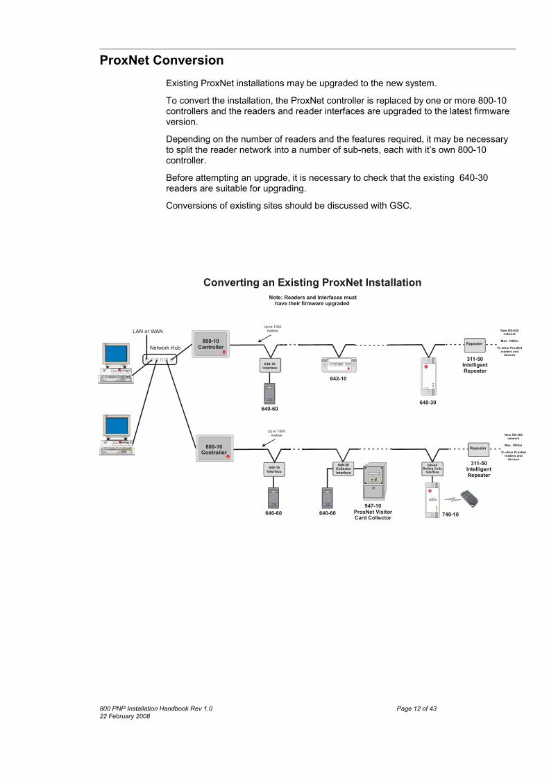
ProxNet ConversionExisting ProxNet installations may be upgraded to the new system.To convert the installation, the ProxNet controller is replaced by one or more 800-10controllers and the readers and reader interfaces are upgraded to the latest firmwareversion.Depending on the number of readers and the features required, it may be necessaryto split the reader network into a number of sub-nets, each with it’s own 800-10controller. Before attempting an upgrade, it is necessary to check that the existing 640-30readers are suitable for upgrading. Conversions of existing sites should be discussed with GSC.
Network Hub
LAN or WANUp to 1000
metres
640-60
ProxNet
640-30
New RS-485 network
Max. 1000mTo other ProxNet
readers and devices
Repeater
311-50Intelligent Repeater
Converting an Existing ProxNet Installation Note: Readers and Interfaces must
have their firmware upgraded
947-10ProxNet VisitorCard Collector
Up to 1000 metres
640-60 640-60
New RS-485 network
Max. 1000mTo other ProxNet
readers and devices
Repeater
311-50Intelligent Repeater
14/05/2007 14:23
642-10
649-10Interface
649-10Interface
649-30CollectorInterface
740-10RECEIVER
740-10
649-40Rolling Code
Interface
800-10Controller
800-10Controller
800 PNP Installation Handbook Rev 1.0 Page 12 of 4322 February 2008
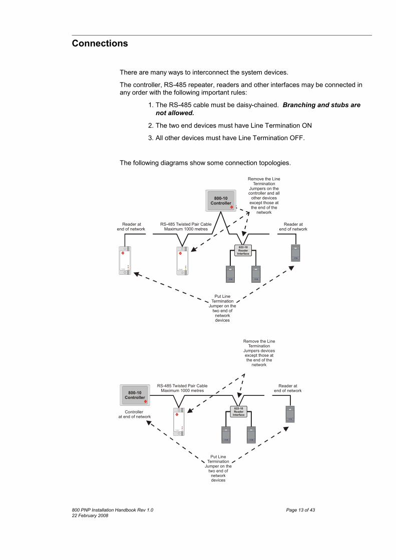
Connections
There are many ways to interconnect the system devices. The controller, RS-485 repeater, readers and other interfaces may be connected inany order with the following important rules:
1. The RS-485 cable must be daisy-chained. Branching and stubs arenot allowed.
2. The two end devices must have Line Termination ON 3. All other devices must have Line Termination OFF.
The following diagrams show some connection topologies.
ProxNe t
RS-485 Twisted Pair CableMaximum 1000 metres
Reader at end of network
Reader at end of network
ProxNe t
Remove the Line Termination
Jumpers on the controller and all
other devices except those at the end of the
network
Put Line Termination
Jumper on the two end of network devices
800-10Controller
649-xxProxNet 2Interface
822-10Reader
Interface
ProxNet
RS-485 Twisted Pair CableMaximum 1000 metres
Controllerat end of network
Reader at end of network
Remove the Line Termination
Jumpers devices except those at the end of the
network
Put Line Termination
Jumper on the two end of
network devices
800-10Controller
649-xxProxNet 2Interface
822-10Reader
Interface
800 PNP Installation Handbook Rev 1.0 Page 13 of 4322 February 2008

Important points to be considered.x Make sure that the polarity of the twisted pair cable is maintained. The
485+ of the controller connects to the 485+ of the readers and RS-485interface. Likewise the 485- of the controller connects to the 485- of thereaders and RS-485 interface.
x Besides the twisted pair 485+ and 485-, a GROUND connection isrequired between all components. If screened cable is used, this mustNOT be the screen.
x If a screened cable is used, make sure that the screen is only connectedat one point otherwise ground-loop currents will result which may causeproblems. It is recommended to connect the screen to the EARTH pointon the controller.
x Due to possible ground potential differences, problems can arise ifRS-485 cables go between different buildings. In these cases use anisolated RS-485 repeater to avoid damage.
x Although the RS-485 specification allows for a maximum cable lengthunder ideal conditions of 1000 metres, in practice electrical noise andother factors may limit the cable length to less. It is suggested that cablelengths should not exceed 700 metres.
800 PNP Installation Handbook Rev 1.0 Page 14 of 4322 February 2008

800-10 Controller The 800-10 Controller consists of a CPU board and an I/O board mounted in a metalhousing. As the user does not need access to the controller, it may be mountedwherever convenient. Installer functions consist of LEDs that indicate system status and a Debug RS-232port which can be connected to a laptop for certain diagnostics.The drawing below shows the controller board and indicates the position of importantitems.
Debug Port - RS-232 port for connection to computer. May be used for diagnosticsunder direction from factory.Network Port - Standard RJ-45 network port for connection to the networkswitch/hubModem Connector - 5-Way terminal block for connection to a standard or GSMmodem (future option)Reset Button - Press to reset the CPU.LEDs - Indicates power and indicates the status of the CPU.Earth Post - Earthing point for the 800-10 and RS-485 network. This MUST beconnected a quality earth point.20 Pin I/O Connector - All connections to the 800-10 controller are made via thisconnector and are detailed below.
800 PNP Installation Handbook Rev 1.0 Page 15 of 4322 February 2008

I/O Connections Connections are listed starting at the top of the I/O connector.COM1, NC1 & NO1Relay 1 voltage free relay connections. The relay is rated at 3A non-inductiveCOMM = CommonNO = Normally Open ContactNC = Normally Closed ContactCOM2, NC2 & NO2Relay 2 voltage free relay connections. The relay is rated at 3A non-inductiveCOMM = CommonNO = Normally Open ContactNC = Normally Closed ContactOCT1 & OCT2Open collector transistor outputs suitable for operating indicators, 3rd partyequipment, relays etc. The outputs can switch 12VDC at 40mA.Note: These outputs are shared with Relay 1 and Relay 2 respectively and have tobe selected between relay output or OCT output with the two jumpers on the board.GND, INPUT1 & INPUT2These inputs can be connected to the GND connection via an external switch orrelay. These inputs can be used as a source to trigger events.
These inputs are NOT suitable for logic level input
GND, INPUT3 & INPUT4These inputs can be connected to the GND connection via an external switch.These inputs are also suitable for logic level input from external devices. Theseinputs can be used as a source to trigger events.485 GND, 485+ & 485-Connection to the RS-485 network must be with twisted pair cable. Polarity of theconnection is important. The RS-485+ must connect to the RS-485+ of the otherreaders, controller and RS-485 repeater. The signal ground must be wired to the 485 GND and to the GND or 485 GND ofother devices.0V & +12VExternal 12V DC supply connection. Polarity is important for unit to operate but thecontroller is protected against reverse connection.EARTHThis connection to be wired to the EARTH post on the controller housing.
800 PNP Installation Handbook Rev 1.0 Page 16 of 4322 February 2008

810-10 RS-485 ReaderThe 810-10 is a self-contained access reader that does not require a reader interfaceto connect to the RS-485 network.The reader provides direct switching for DC door strikes and magnetic locks and has inputs for Door Monitoring, Exit push button and Alarm/Inhibit functions. An opencollector output is also provided that is suitable for driving a 12VDC relay. The reader can switch a maximum of 3A for 1 second or 500mA continuous.
DoorStrike
Door Monitor Switch
Remote doorRS-485 Networktwisted-pair cable
810-10 RS-485 Reader Connections
Connect to external switch as atrigger input
orto inhibit access at this reader
The switch must be normallyclosed
Trigger/Inhibit Function & OCT Output
810-10Reader
White
Diode tosuppress back-EMFMount as close as
possible to the strike
+-
Remote Door Releasenormally openpush-button
Door MonitorSwitch
must open whendoor opens
Brown
Yellow
Red
GreenBlackTo 810-10
OrangeBlue
Purple
BlackTo 810-10
485+485-GND
Add link if linetermination
required
RS-485 Connections
+-
Red
GrayBlackTo 810-10
Diode tosuppress back-EMF
Example of use ofthe OCT output todrive an external
12V relay
800 PNP Installation Handbook Rev 1.0 Page 17 of 43
22 February 2008

811-10 Reader The drawing below shows the reader board and base indicating the position ofimportant items.
Line Termination Jumper
Clear Jumper
Clear JumperUsed to clear the memory of the reader. If a reader is removed from the system orneeds to have a new address assigned, it must first be cleared. To clear memory, briefly short the Clear jumper and all the LEDs will light. After about 3 seconds all the LEDs will flash indicating the reader is in the “ClearedMemory” state and ready for programming.
Line Termination JumperIf the reader is at the end of the RS-485 cable this jumper must be on to connect theline termination resistor.If the reader is not at the end of the cable, the jumper must be off.
I/O ConnectorAll the connections to the reader are made at this connector and are detailed belowCOIL 1, COIL 2, YEL, RED, GRN & COM (Not available on the 816-10)These functions are not used on the 811-10 reader as it does not support a remotereadhead.AC/DCThe reader supply is 12 volts and may be AC or DC. The reader cannot be damagedby reverse supply connection.
800 PNP Installation Handbook Rev 1.0 Page 18 of 4322 February 2008
485+ & 485-Connection to the RS-485 network must be with twisted pair cable. Polarity of theconnection is important. The RS-485+ must connect to the RS-485+ of the otherreaders, controller and RS-485 repeater.DoorConnection for the door monitor switch (normally closed switch). If the reader isconfigured with DOOR SWITCH checked, then transactions are only logged if thedoor monitor switch operates when the door opens. The switch must open when thedoor opens.PushConnection for remote door open push-button.Relay (N/C, N/O & Com)Voltage free connection to the relay. The contacts are rated at 3A non inductive load.The connections are:
N/C = Normally Closed. N/O = Normally Open. Com = Common
Alarm (Inhibit)Alarm input to trigger alarm condition or, if so configured, reader inhibit. In thenormal state this input must be connected to Ground. A break in the connection toGround will cause an alarm or inhibit thereby barring all access at the reader.TamperConnection to the reader Tamper switch. This switch is normally closed when thereader is assembled and opens if the reader is disassembled. The common of thetamper switch is connected to Ground.The Tamper connection can be linked to the Alarm connection to trigger an alarmcondition at the controller.Ground485 GROUND connection and common connection for the switches.
800 PNP Installation Handbook Rev 1.0 Page 19 of 4322 February 2008

Typical Connections - 811-10The drawing on this page shows typical connections to the ProxNet Reader.
DoorStrike
Door Monitor Switch
Remote doorRS-485 Networktwisted-pair cable
Normally Open Strike(Fail Open)
ProxNet
Remote ReadheadConnection
Connect to externalswitch to trigger alarm
at the controlleror
to inhibit access at thisreader
The switch must benormally closed
Tamper, Alarm & Inhibit Functions
Diode tosuppress Back-EMF
+-
Remote DoorRelease
normally openpush-button
Door MonitorSwitch
must open whendoor opens
811-10Reader
Make this link toconnect the tamperswitch to the alarminput. If the tamper
switch operates, thealarm is triggered at
the controller
Diode tosuppress back-EMF
+-
Remote DoorRelease
normally openpush-button
Door MonitorSwitch
must open whendoor opens
The RemoteReadhead is not supported
on the 811-10 Reader
800 PNP Installation Handbook Rev 1.0 Page 20 of 43
22 February 2008

816-10 LCD Reader (642-10)The LCD Reader plugs into the same base as the standard reader but does not havethe convenience of a ribbon cable. When plugging the LCD reader into the base takecare to ensure the plug and socket are correctly aligned.Except for the operation of the Clear Jumper, all other connections and functions areidentical to the standard reader.If this reader is to be used as part of a T&A clocking system, the reader can beconfigured as either a Clock IN, Clock OUT or Clock Non-directional reader.(Note that the connection information is identical to that of the 642-10)
Clear JumperUsed to clear the memory of the reader. If a reader is removed from the system orneeds to have a new address assigned, it must first be cleared. Unlike the normal reader, this unit does not have a ribbon cable and the resetprocedure is as follows:
1. Unplug LCD reader2. Slide on reset jumper3. Plug reader into base4. Wait for reset to complete - all 3 LEDs flashing5. Unplug LCD reader6. Remove reset jumper7. Plug reader into base.
Remote Readheads cannot be used with the LCD Reader.
800 PNP Installation Handbook Rev 1.0 Page 21 of 4322 February 2008
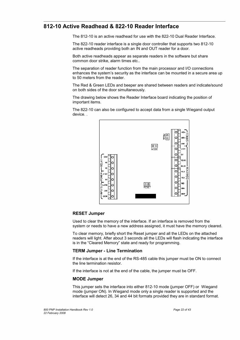
812-10 Active Readhead & 822-10 Reader Interface The 812-10 is an active readhead for use with the 822-10 Dual Reader Interface.The 822-10 reader interface is a single door controller that supports two 812-10active readheads providing both an IN and OUT reader for a door.Both active readheads appear as separate readers in the software but sharecommon door strike, alarm times etc..The separation of reader function from the main processor and I/O connectionsenhances the system’s security as the interface can be mounted in a secure area upto 50 meters from the reader.The Red & Green LEDs and beeper are shared between readers and indicate/soundon both sides of the door simultaneously.The drawing below shows the Reader Interface board indicating the position ofimportant items.The 822-10 can also be configured to accept data from a single Wiegand outputdevice. .
RESET JumperUsed to clear the memory of the interface. If an interface is removed from thesystem or needs to have a new address assigned, it must have the memory cleared. To clear memory, briefly short the Reset jumper and all the LEDs on the attachedreaders will light. After about 3 seconds all the LEDs will flash indicating the interfaceis in the “Cleared Memory” state and ready for programming.TERM Jumper - Line TerminationIf the interface is at the end of the RS-485 cable this jumper must be ON to connectthe line termination resistor.If the interface is not at the end of the cable, the jumper must be OFF.MODE JumperThis jumper sets the interface into either 812-10 mode (jumper OFF) or Wiegandmode (jumper ON). In Wiegand mode only a single reader is supported and theinterface will detect 26, 34 and 44 bit formats provided they are in standard format.
800 PNP Installation Handbook Rev 1.0 Page 22 of 4322 February 2008

ConnectorsThe functions and wiring of all connections are identical to those listed for theProxNet reader with the exception of the connections marked “READER(S)” whichare detailed below.
BLUEBLUEBeeper controlBEEPGREENGREENGreen LED controlGRN
ORANGEORANGERed LED controlRED
YELLOWReader 1 Yellow LEDcontrol
YEL1
YELLOWReader 2 Yellow LEDcontrol
YEL2
WHITE812-10 - Reader 1 DataWiegand - D1 connection
R1/D1
WHITE812-10 - Reader 2 DataWiegand - D0 connection
R2/D0
BLACKBLACKNegative supply toReader
0REDREDPositive supply to Reader12
812-10 Wire ColourReader 2
812-10 Wire ColourReader 1
FunctionConnection
485+, 485- & GNDConnection to the RS-485 network must be with twisted pair cable. Polarity of theconnection is important. The RS-485+ must connect to the RS-485+ of the otherreaders , controller and RS-485 repeater. The signal ground as detailed on page 27is connected to GND.Wiegand ModeIn Wiegand Mode (MODE jumper on) the interface will accept 26, 34 and 44 bitWiegand data in the formats described below:26 bit mode
x The first bit is the even parity of tag bits 17-28.x The next 24 bits are the least significant 24 bits of the code (MSB first).x The last bit is the odd parity of tag bits 29-40.
34 bit modex The first bit is the even parity of tag bits 9-24.x The next 32 bits are the least significant 32 bits of the code (MSB first).x The last bit is the odd parity of tag bits 25-40.
44 bit modex The first 40 bits are the least significant 40 bits of the code (MSB first).x The last 4 bits are the LRC value of the 10 previous nibbles. The LRC is
calculated by XORing each nibble. The MSB of the LRC is sent first.
800 PNP Installation Handbook Rev 1.0 Page 23 of 4322 February 2008

Wiegand ConnectionsThe data connections from the Wiegand reader are connected as follows:
R1/D1D1R2/D0D0
822-10 InterfaceWiegand Reader
If the reader can accept 12VDC, wire the power leads to the +12V & 0V connections.
Other connections vary depending on what functions the Wiegand reader allows.LED and beeper control is available on the connections YEL1, RED, GRN & BEEP.These are open collector outputs and capable of sinking 30mA and are normallycompatible with Wiegand reader control.AddressThe reader address is stored in the interface unit and not in the reader and theprocedure is the same as for all other readers.
Changing an 812-10 reader does not require re-addressing the unit.
Changing an interface does require the readers to be re-addressed
812-10 ReaderThe unit is supplied with a 1 m cable. The table below details the function of eachwire.
Connect 0V from power supply.0VBLACKConnect 11-14V from power supply.+VDCREDControls SounderBEEPBLUEControls Green LED.GRN-LEDGREENControls Red LED.RED-LEDORANGEControls Yellow LED.YEL-LEDYELLOWOutputs RFID tag data.DATAWHITE
FunctionNameColour
Connections to the 822-10 Reader Interface are detailed in the section starting onpage 25.
Mounting ConsiderationsNormally readers can be mounted in close proximity to each other but because ofdifferences in circuitry, 811-10 readers and 812-10 readers must be kept apart.
A 812-10 Reader MUST NOT be mounted closer than500mm to a 811-10 or a 640-50 Remote Readhead as
they will interfere with each other and degradeperformance.
800 PNP Installation Handbook Rev 1.0 Page 24 of 4322 February 2008

Typical Connections - 812-10 Reader and 822-10 Interface
DoorStrike
Door Monitor Switch
Remote doorRS-485 Networktwisted-pair cable
812-10 Reader 1Connection
Connect an external switch totrigger alarm at the controller
to inhibit access at this readerThe switch must be normally
closed
or
Alarm & Inhibit Functions
Blue
Yellow
Red
Green
BlackWhite
To MiniReader
Door & Strike Connections
Diode tosuppressBack-EMF
Remote DoorRelease
normally open push-button
Door Monitor Switchmust open when
door opens
Orange
Link +12 & NC for FAIL OPEN
Link +12 & NO for FAIL CLOSED
Blue
Yellow
Red
Green
BlackWhite
To MiniReader
Orange
812-10 Reader 2Connection
822-10812-10812-10
+-
800 PNP Installation Handbook Rev 1.0 Page 25 of 43
22 February 2008

Addressing ReadersReader addressing is automatic during the reader detection process from theProxnetPro host software.Reader addressing is explained in a separate “How To” document.Reader LEDs indicate the state of the reader.
Yellow flashing fasterConfiguration Complete - Reader ready
Yellow flashing slowly - other LEDs offTag flashed at reader to set addressand waiting for configuration
All flashing - Yellow flashing faster thanthe other LEDs
Controller in the Add Reader mode andreader is ready to be addressed.
All FlashingReset - no addressLEDsState/Action
Reader Address IDThe address of a reader is stored in memory. The reader has a feature that allowsthis address to be displayed by use of a special diagnostic card ( or use the TagSimulator set to number 0987654321). This card causes the 3 LEDs to flash insequence and by counting the flashes the address can be decoded.
1. Present the diagnostic card to the reader2. The GREEN LED will flash - count the number of flashes = Hundreds3. Next the RED LED will flash - count the number of flashes = Tens4. Next the YELLOW LED will flash - count the number of flashes = Units.
For example 1 flash GREEN = 1004 flashes RED = 407 flashes YELLOW = 7The address is therefore 147
800 PNP Installation Handbook Rev 1.0 Page 26 of 4322 February 2008

System Wiring A clean signal return path is essential for reliable performance on a RS 485 networkand a Common Ground wire connection must be provided between all of the networkcomponents. In addition networks between buildings with different earthing pointsneed isolation to avoid problems and possible damage.
Common Ground Wire ConnectionA common ground wire must connect between the GROUND connection on thereaders, interfaces, repeaters and the GND connection on the 800-10 controller.To prevent unintentional earthing of this common ground, it is essential to usefloating power supplies in which the negative output is NOT connected to Earth. Werecommend using the GSC System’s Power Supply (Part No: 120-20 & 30).The common ground wire is earthed at the controller and the controller EARTHconnection must be connected to the building earth point to ensure the system iscorrectly earthed. This is normally done via the 120-20 or -30 power supply.Earthing at more than one point (i.e. using earthed power supplies) could causedamage to equipment during earth fault conditions.
Opto-Isolated RS 485 repeaterIf the RS-485 network extends between buildings, 311-50(12VDC) opto-Isolatedrepeater must be used to prevent possible damage to components due to potentialdifferences between buildings. The same applies for large buildings with separateearth networks.The Opto-Isolated unit provides earthing for the isolated side of the network and it’sEARTH connection must be connected to the building earth point.
CablesRecommended cable is: Mylar screened Category 5 cable with 2 twisted pair multi-strand 0.22mm2 wires.This cable is used extensively by the computer industry and is inexpensive.
Solid core wire is NOT recommended
The drawings below show how to use a 2 pair twisted pair cable to provide the 485+,485- and GROUND wires. If Shielded cable is used the shield must NOT be used as the GROUND wire.
485+485-GND
485+485-GND
SHIELD
800 PNP Installation Handbook Rev 1.0 Page 27 of 4322 February 2008

ProxNet
311-50
RS-485 Repeaterat end of local network
ProxNet
Opto-Isolated network
Earth connection for local networkTo nearest building EARTH
Earth connection foropto-isolated network
To nearest building EARTH
Twisted Pair CableCommon Ground
for isolated network
Power Supply, Common Groundand EARTH Connections
Common Groundfor local network
Twisted Pair Cablefor isolated network
120-20+-
EARTH
12 VDC220VAC
120-20
220VAC
120-20
220VAC
120-20
220VAC
Power
800-10Controller
Power
800 PNP Installation Handbook Rev 1.0 Page 28 of 43
22 February 2008
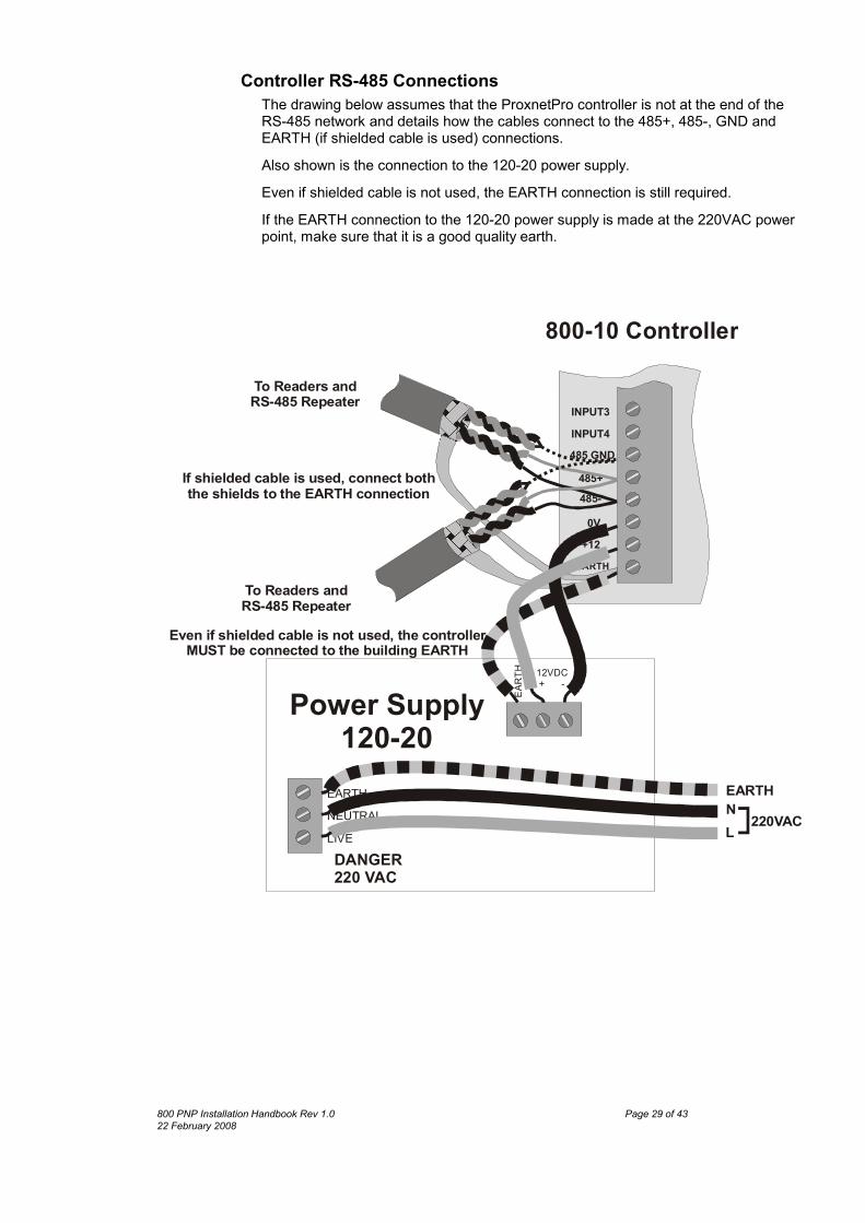
Controller RS-485 ConnectionsThe drawing below assumes that the ProxnetPro controller is not at the end of theRS-485 network and details how the cables connect to the 485+, 485-, GND andEARTH (if shielded cable is used) connections.Also shown is the connection to the 120-20 power supply. Even if shielded cable is not used, the EARTH connection is still required. If the EARTH connection to the 120-20 power supply is made at the 220VAC powerpoint, make sure that it is a good quality earth.
485+
EARTH
485-
485 GNDINPUT4
+120V
INPUT3
To Readers and RS-485 Repeater
To Readers and RS-485 Repeater
If shielded cable is used, connect boththe shields to the EARTH connection
EART
H 12VDC + -
EARTHNEUTRALLIVEDANGER220 VAC
EARTHNL 220VAC
Power Supply120-20
800-10 Controller
Even if shielded cable is not used, the controllerMUST be connected to the building EARTH
800 PNP Installation Handbook Rev 1.0 Page 29 of 4322 February 2008
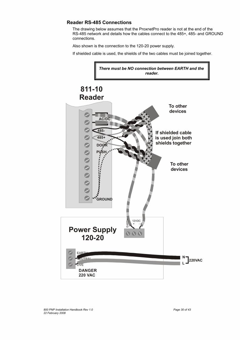
Reader RS-485 ConnectionsThe drawing below assumes that the ProxnetPro reader is not at the end of theRS-485 network and details how the cables connect to the 485+, 485- and GROUNDconnections.Also shown is the connection to the 120-20 power supply. If shielded cable is used, the shields of the two cables must be joined together.
There must be NO connection between EARTH and thereader.
485+
To otherdevices
485-
DOORPUSH
If shielded cable is used join bothshields together
AC/DC
GROUND
EART
H 12VDC + -
EARTHNEUTRALLIVEDANGER220 VAC
NL 220VAC
Power Supply120-20
To otherdevices
811-10Reader
800 PNP Installation Handbook Rev 1.0 Page 30 of 4322 February 2008
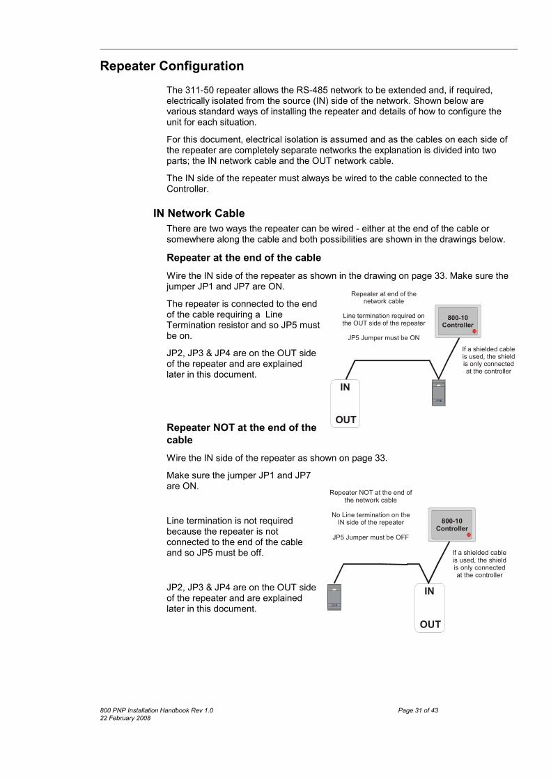
Repeater ConfigurationThe 311-50 repeater allows the RS-485 network to be extended and, if required,electrically isolated from the source (IN) side of the network. Shown below arevarious standard ways of installing the repeater and details of how to configure theunit for each situation.For this document, electrical isolation is assumed and as the cables on each side ofthe repeater are completely separate networks the explanation is divided into twoparts; the IN network cable and the OUT network cable.The IN side of the repeater must always be wired to the cable connected to theController.
IN Network CableThere are two ways the repeater can be wired - either at the end of the cable orsomewhere along the cable and both possibilities are shown in the drawings below.Repeater at the end of the cableWire the IN side of the repeater as shown in the drawing on page 33. Make sure thejumper JP1 and JP7 are ON.The repeater is connected to the endof the cable requiring a LineTermination resistor and so JP5 mustbe on.JP2, JP3 & JP4 are on the OUT sideof the repeater and are explainedlater in this document.
Repeater NOT at the end of thecableWire the IN side of the repeater as shown on page 33.Make sure the jumper JP1 and JP7are ON.
Line termination is not requiredbecause the repeater is notconnected to the end of the cableand so JP5 must be off.
JP2, JP3 & JP4 are on the OUT sideof the repeater and are explainedlater in this document.
800 PNP Installation Handbook Rev 1.0 Page 31 of 4322 February 2008
IN
OUT
If a shielded cable is used, the shield is only connected at the controller
Repeater at end of the network cable
Line termination required on the OUT side of the repeater
JP5 Jumper must be ON
800-10Controller
IN
OUT
If a shielded cable is used, the shield is only connected at the controller
Repeater NOT at the end of the network cable
No Line termination on the IN side of the repeater
JP5 Jumper must be OFF
800-10Controller

OUT Network CableThe OUT side of the repeater creates a new isolated network cable. If this cable isshielded, then the shield must only be connected to the OUT connector of therepeater as detailed in the handbook.There are two ways the repeater can be wired - either at the end of the cable orsomewhere along the cable and both possibilities are shown in the drawing below.
Repeater at the end of the cableWire the OUT side of the repeater as shown in the drawing at the end of thisdocument. The repeater is connected to the end ofthe cable requiring a Line Terminationresistor and so JP4 must be on.JP2 & JP3 are used to bias the 485+ &485- cables in a particular way andmust always be on.
Repeater NOT at the end of thecable
Wire the OUT side of the repeater as shown in the drawing on page 33.Line termination is not required because the repeater is not connected to the end ofthe cable and so JP4 mustbe off.JP2 & JP3 are used to biasthe 485+ & 485- cables ina particular way and mustalways be on.
Cascading RepeatersIf the cable runs are solong that additionalrepeaters are required, it isessential that the OUT ofthe one repeater isconnected to the IN of thenext repeater in the chain. Wiring and jumper settings are the same as described in
800 PNP Installation Handbook Rev 1.0 Page 32 of 4322 February 2008
IN
OUT
Repeater at end of the network cable
Line termination required on the OUT side of the
repeaterJP4 Jumper must be ON
If a shielded cable is used, the shield is only connected
to the OUT connector block of
the Repeater
IN
OUT
Repeater NOT at the end ofthe network cable
No Line termination on the OUT side of the repeaterJP4 Jumper must be OFF
If a shielded cable is used, the shield is only connected
to the OUT connector block of
the Repeater
this document.Each isolated network cable can be a maximum of 1000
metres Electrical noise may reduce the maximum cable length
that can be used.
IN OUT
IN OUT
800-10Controller
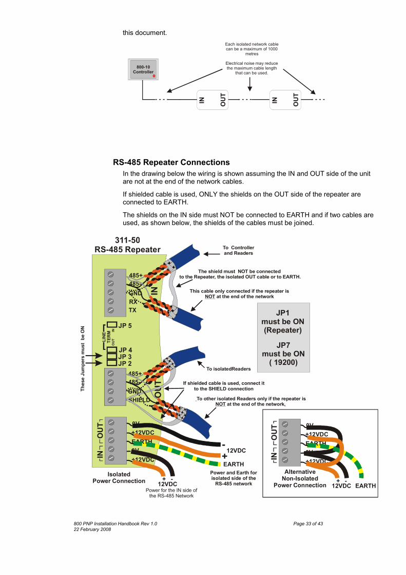
RS-485 Repeater ConnectionsIn the drawing below the wiring is shown assuming the IN and OUT side of the unitare not at the end of the network cables. If shielded cable is used, ONLY the shields on the OUT side of the repeater areconnected to EARTH. The shields on the IN side must NOT be connected to EARTH and if two cables areused, as shown below, the shields of the cables must be joined.
OUT
To Controller and Readers
311-50RS-485 Repeater
TX
LINE
TERM
RX
485+485-GND IN
485+485-
SHIELDGND
OUT
To isolatedReaders
The shield must NOT be connected to the Repeater, the isolated OUT cable or to EARTH.
If shielded cable is used, connect it to the SHIELD connection
L
Thes
eJum
pers
must
beON
This cable only connected if the repeater is at the end of the networkNOT
NOT .To other isolated Readers only if the repeater is
at the end of the network
JP 5
JP 4JP 3JP 2
IN
JP7 must be ON
( 19200)
JP1 must be ON(Repeater)
0V+12VDCEARTH0V+12VDCIN
OUT
12VDC EARTH+ -Alternative
Non-IsolatedPower Connection
0V+12VDCEARTH0V+12VDCIN
OUT
12VDC
EARTH
+ -IsolatedPower Connection
12VDC-+
Power and Earth for isolated side of the
RS-485 networkPower for the IN side of
the RS-485 Network
800 PNP Installation Handbook Rev 1.0 Page 33 of 4322 February 2008

Power SupplyThe 311-50 is an opto-isolated repeater and if electrical isolation is required, aseparate power supplies is required for the IN and OUT sections of the repeater.Electrical Isolation RequiredWhere electrical isolation is required each side of the repeater requires a separatepower supply. If the unit is mounted close to the last reader of the IN side of the network the INpower can be provided by the last reader’s power supply and a separate powersupply used to power the OUT side of the repeater. The EARTH connection must be provided by the OUT side power supply.Electrical Isolation Not RequiredIn applications where electrical isolation is not required, simply connect both IN &OUT 0V connections to the 0V of the power supply and connect both the IN & OUT+12VDC to the +12V of the power supply. The EARTH connection is required as detailed above.
800 PNP Installation Handbook Rev 1.0 Page 34 of 4322 February 2008
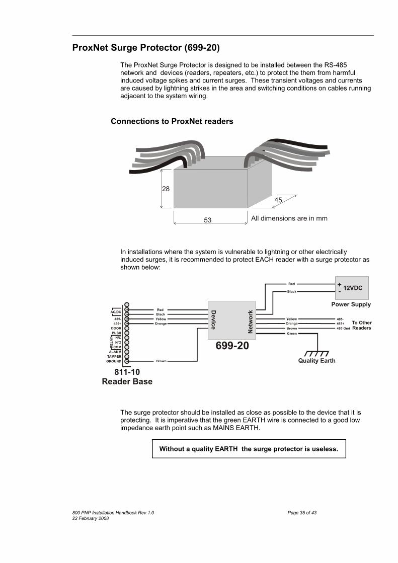
ProxNet Surge Protector (699-20)The ProxNet Surge Protector is designed to be installed between the RS-485network and devices (readers, repeaters, etc.) to protect the them from harmfulinduced voltage spikes and current surges. These transient voltages and currentsare caused by lightning strikes in the area and switching conditions on cables runningadjacent to the system wiring.
Connections to ProxNet readers
53
4528
All dimensions are in mm
In installations where the system is vulnerable to lightning or other electricallyinduced surges, it is recommended to protect EACH reader with a surge protector asshown below:
699-20
Power Supply
+- 12VDC
Quality Earth811-10
Reader Base
Device
Netw
ork
To OtherReaders
The surge protector should be installed as close as possible to the device that it isprotecting. It is imperative that the green EARTH wire is connected to a good lowimpedance earth point such as MAINS EARTH.
Without a quality EARTH the surge protector is useless.
800 PNP Installation Handbook Rev 1.0 Page 35 of 4322 February 2008
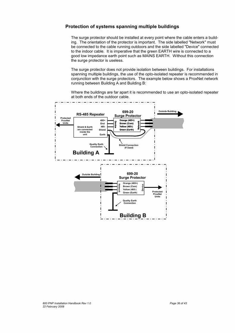
Protection of systems spanning multiple buildings
The surge protector should be installed at every point where the cable enters a build-ing. The orientation of the protector is important. The side labelled "Network" mustbe connected to the cable running outdoors and the side labelled "Device" connectedto the indoor cable. It is imperative that the green EARTH wire is connected to agood low impedance earth point such as MAINS EARTH. Without this connectionthe surge protector is useless.
The surge protector does not provide isolation between buildings. For installationsspanning multiple buildings, the use of the opto-isolated repeater is recommended inconjunction with the surge protectors. The example below shows a ProxNet networkrunning between Building A and Building B:
Where the buildings are far apart it is recommended to use an opto-isolated repeaterat both ends of the outdoor cable.
RS-485 Repeater
Earth
485+Gnd485-
Shield
Quality EarthConnection
Shield & Earthare connected
inside theunit
699-20Surge Protector
Shield Connection (If Used)
Outside Building
ProtectedProxNet
Units
Outside Building
Quality EarthConnection
ProtectedProxNet
Units
Building B
Building A
Orange (485+)Brown (Com)Yellow (485-)Green (Earth) Ne
twor
kDeviceOrange (485+)Brown (Com)Yellow (485-)Green (Earth) Ne
twor
kDevice
Orange (485+)Brown (Com)Yellow (485-)Green (Earth)
Network Devic
e
699-20Surge Protector
800 PNP Installation Handbook Rev 1.0 Page 36 of 4322 February 2008

4 - Channel I/O Unit 820-10The 820-10 I/O Module provides 4 inputs and 4 relay outputs with voltage freecontacts. Inputs and outputs are completely independent of each other and areconfigured using the “trigger” functions of the system.
For details on the use of triggers see the “How To” documents.For assistance of specific applications contact GSC.
Red, Green & Yellow
Status LEDs
Address SetJumper
Clear Jumper
IN1 to IN4Input Pull-up
Resistor Select
Line TerminationJumper
Tamper InputSelect Jumper
Connections
TAMP+ & TAMP-These two terminals are for an optional external tamper input. If an external tamperswitch is used, the TAMPER input jumper must be moved to the EXT position.If the internal Tamper switch is used the TAMPER input jumper must be moved tothe INT position.RELAY-1 to -4These are 4 output relays that have voltage free contacts. The connections are:
NC Normally Closed contactNO Normally Open contactCOM Common contact
The contacts are rated at:5A @ 120VAC for non-inductive loads2.5A @ 240VAC for non-inductive loads3A @ 28VDC for inductive loads
800 PNP Installation Handbook Rev 1.0 Page 37 of 4322 February 2008
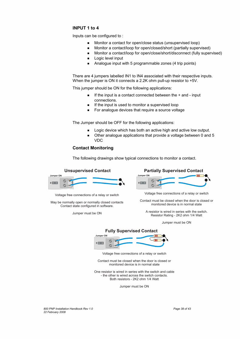
INPUT 1 to 4Inputs can be configured to :
x Monitor a contact for open/close status (unsupervised loop)x Monitor a contact/loop for open/closed/short (partially supervised)x Monitor a contact/loop for open/close/short/disconnect (fully supervised)x Logic level inputx Analogue input with 5 programmable zones (4 trip points)
There are 4 jumpers labelled IN1 to IN4 associated with their respective inputs.When the jumper is ON it connects a 2.2K ohm pull-up resistor to +5V. This jumper should be ON for the following applications:
x If the input is a contact connected between the + and - inputconnections.
x If the input is used to monitor a supervised loop x For analogue devices that require a source voltage
The Jumper should be OFF for the following applications:x Logic device which has both an active high and active low output.x Other analogue applications that provide a voltage between 0 and 5
VDCContact Monitoring
The following drawings show typical connections to monitor a contact.
INPUT
+Jumper ON
Fully Supervised Contact
-IN
Voltage free connections of a relay or switchContact must be closed when the door is closed or
monitored device is in normal stateOne resistor is wired in series with the switch and cable
- the other is wired across the switch contacts.Both resistors - 2K2 ohm 1/4 Watt
Jumper must be ON
INPUT
+Jumper ON
Unsupervised Contact
-IN
Voltage free connections of a relay or switchMay be normally open or normally closed contacts
Contact state configured in software.Jumper must be ON
INPUT
+Jumper ON
Partially Supervised Contact
-IN
Voltage free connections of a relay or switchContact must be closed when the door is closed or
monitored device is in normal state
A resistor is wired in series with the switch.Resistor Rating - 2K2 ohm 1/4 Watt
Jumper must be ON
800 PNP Installation Handbook Rev 1.0 Page 38 of 4322 February 2008

In the Partially Supervised Contact example, the system can identify threestates:
x Contact opened or wire disconnected.x Contact closed.x Wire short circuited.
In the Fully Supervised Contact example the system can identify four states:x Contact opened. x Contact closed.x Wire disconnected.x Wire short circuited.
The system software will set default trip values when you select these modesand give the option of setting which states will give rise to an Alarm condition.
Other Monitoring
The inputs may also be used to monitor analogue levels as shown below.
INPUT
+Jumper OFF
Analog Input
-IN
External analog source voltage must not exceed5 VDC
Inputs are NOT protected against reverse polarity
Jumper must be OFF
To external analog source+-INPUT
+Jumper ON
Thermistor Temperature Sensor
-IN
Analog input example usingRS Components thermistor part# 151-215
Approximate input voltages:10 C-3.8V2 4
0VInput resolution aprox. 0.02V
Jumper must be ON
o
0 C-3. V30 C-3.
o
o
In the software the trip points are set as a percentage of the input range.
The input range is 0 - 5 VDC with 0V = 0% and 5V = 100%
Thus in the Temperature Sensor example the settings would be:
60%33068%3.42076%3.810
PercentVoltageDeg C
Note that a thermistor is an inverse device - as the temperature goes up, theresistance and therefore the voltage goes down.
The input can measure voltage in the range 0 to 5 VDC.
Note that there is no input protection for over voltage orreverse voltage.
It is also important to establish that there is no potential difference between theInput - connection and the source’s 0V as this could cause damage to the820-10.
800 PNP Installation Handbook Rev 1.0 Page 39 of 4322 February 2008

485+, 485- & GNDConnection to the RS-485 network must be with twisted pair cable. Polarity of theconnection is important. The RS-485+ must connect to the RS-485+ of the otherreaders, interfaces and controller. Besides the twisted pair 485+ and 485-, aGROUND connection is required between all devices on the RS-485 bus and thismust be connected to the GND terminal.If screened cable is used, do not use the screen as this GROUND wire.0V & 12V DCPower connection for the unit. Power supply must be 12 Volts DC. EARTHConnect to a suitable EARTH connection on the power supply. This earth provides areturn path for protection of both the RS-485 lines and the inputs.
LEDSThere are 3 LEDs that indicate the status of the unit.
ADDR JumperThis jumper is used to assign an address to the unit.The addressing procedure is identical to that of a reader and is detailed on page 26with the exception that instead of flashing a tag the ADDR jumper is briefly shorted.
Termination JumperWhen this unit is installed at the END of the RS-485 network the TERM jumper mustbe ONIf the unit is not at the end of the RS-485 network the TERM jumper must be OFF.
CLR - Reset JumperTo clear the unit’s memory and address, briefly short the CLR jumper. All 3 LEDs flashing indicate that the unit is in the factory reset state.
800 PNP Installation Handbook Rev 1.0 Page 40 of 4322 February 2008

Controller NetworkAlthough it is possible to connect the controllers and PCs together on a dedicatedprivate network (cabled by the installer), it is more likely that they will be connectedto a company’s existing network.
Unless connected to a simple in-house network, it will be necessary toconsult the company’s IT manager for permission and settings.
The 800-10 controller is connected to the PC and other controllers via a system of hubs, switches and network cables.
Network Hub
LAN or WAN
To other ProxNet readers
To other ProxNet readers
800-10Controller
800-10Controller
Each controller has to be assigned a static IP address. In sites with large network installations, the IT manager will allocate the IPaddresses.In sites with small networks, the IP addresses can be decided based on inspection ofthe existing network and allocating unused IP addresses.
Cabling considerationThe 800-10 controller supports 100 Mbit/s and is based on the 100BASE-T networkstandard.The recommended cable for this standard is UTP Cat 5 and the maximum total cablelength between controller and hub/switch is 100 metres - good practice is to limit thisto 90 meters so as to allow for possible patch cables at either end.It is important to wire the RJ-45 connector correctly and the T-568B standard shownbelow is recommended.
\
800 PNP Installation Handbook Rev 1.0 Page 41 of 4322 February 2008
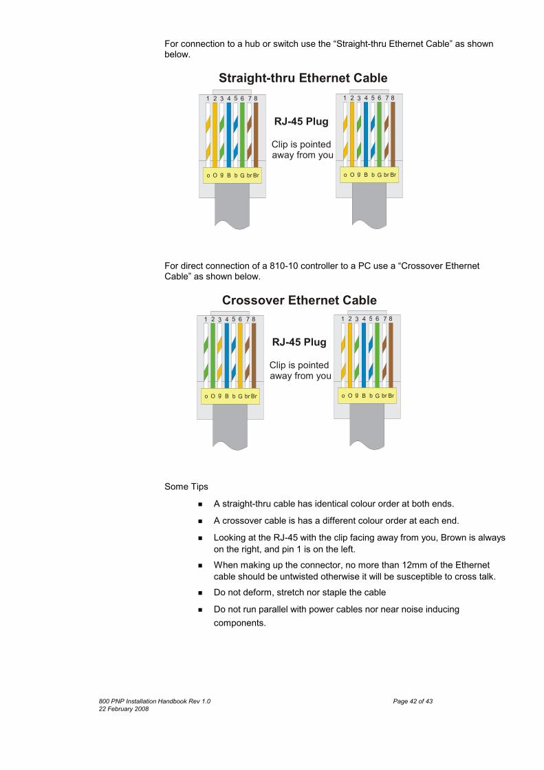
For connection to a hub or switch use the “Straight-thru Ethernet Cable” as shownbelow.
o O g GB b br Br
1 2 3 4 5 6 7 8
o O g GB b br Br
1 2 3 4 5 6 7 8
RJ-45 PlugClip is pointed away from you
Straight-thru Ethernet Cable
For direct connection of a 810-10 controller to a PC use a “Crossover EthernetCable” as shown below.
o O g GB b br Br
1 2 3 4 5 6 7 8
o O g GB b br Br
1 2 3 4 5 6 7 8
RJ-45 PlugClip is pointed away from you
Crossover Ethernet Cable
Some Tipsx A straight-thru cable has identical colour order at both ends. x A crossover cable is has a different colour order at each end.x Looking at the RJ-45 with the clip facing away from you, Brown is always
on the right, and pin 1 is on the left. x When making up the connector, no more than 12mm of the Ethernet
cable should be untwisted otherwise it will be susceptible to cross talk. x Do not deform, stretch nor staple the cablex Do not run parallel with power cables nor near noise inducing
components.
800 PNP Installation Handbook Rev 1.0 Page 42 of 4322 February 2008

Addressing the ControllerController addressing is done from the ProxnetPro software and is detailed in the“How To” document on controller addressing.
Changing ReadersUnlike other systems where the reader’s only function is to read the card, in thissystem the reader stores address data in it’s non-volatile memory.Moving a reader to another position in the system does NOT change the readeraddress. See the “How To” document on reader Re-Addressing
Physical Dimensions and Mounting DetailsThis section details the dimensions of the system devices.810-10 and 812-10
30
76.6
25.8
44.5
88.5
All measurements in mm.Drawing not to scale
cable exit hole
4 mounting holes 3.5mm dia.
centred
TOP
The Mini Reader consists of three parts: a potted unit containing the electronics, afront cover, and an optional spacer plate. A fixed 7-way colour-coded cableprotrudes from the back of the potted unit.
If the spacer plate is used the reader cable may be brought out of one of four exitpoints on the spacer: top, bottom, left or right. This enables the cable to be run onthe surface of the wall. If no spacer plate is used a minimum hole size of 6.5mmmust be drilled in the wall at the cable exit position as shown above to allow thecable to exit perpendicular to the reader.The optional spacer plate may also be used when mounting the reader on a metalsurface to reduce the negative effects of metal on the read range.
800 PNP Installation Handbook Rev 1.0 Page 43 of 4322 February 2008