wood torrefaction – pilot tests and utilisation · vtt technology 122 wood torrefaction – pilot...
TRANSCRIPT
Wood torrefaction – pilot tests and utilisation prospects
Carl Wilén | Perttu Jukola | Timo Järvinen | Kai Sipilä | Fred Verhoeff | Jaap Kiel
•VISIONS•S
CIE
NC
E•T
ECHNOLOGY•R
ES
EA
RC
HHIGHLIGHTS
122


VTT TECHNOLOGY 122
Wood torrefaction – pilot testsand utilisation prospects
Carl Wilén, Perttu Jukola, Timo Järvinen & Kai SipiläVTT
Fred Verhoeff & Jaap KielEnergy research Centre of the Netherlands
ISBN 978-951-38-8046-0 (Soft back ed.)ISBN 978-951-38-8047-7 (URL: http://www.vtt.fi/publications/index.jsp)
VTT Technology 122
ISSN-L 2242-1211ISSN 2242-1211 (Print)ISSN 2242-122X (Online)
Copyright © VTT 2013
JULKAISIJA – UTGIVARE – PUBLISHER
VTTPL 1000 (Tekniikantie 4 A, Espoo)02044 VTTPuh. 020 722 111, faksi 020 722 7001
VTTPB 1000 (Teknikvägen 4 A, Esbo)FI-02044 VTTTfn +358 20 722 111, telefax +358 20 722 7001
VTT Technical Research Centre of FinlandP.O. Box 1000 (Tekniikantie 4 A, Espoo)FI-02044 VTT, FinlandTel. +358 20 722 111, fax +358 20 722 7001
Kopijyvä Oy, Kuopio 2013
3
Wood torrefaction – pilot tests and utilisation prospectsPuun torrefiointi – pilot-kokeet ja käytön edellytykset.Carl Wilén, Perttu Jukola, Timo Järvinen, Kai Sipilä, Fred Verhoeff & Jaap Kiel.Espoo 2013. VTT Technology 122. 73 p.
AbstractThe research project “Torrefaction of woody biomasses as energy carriers for theEuropean markets” was carried out within the Tekes BioRefine programme in2010–2012 and was coordinated by VTT. The main objective of the project was tocreate a discussion platform and collate basic information for the Finnish industrialstakeholders involved in developing torrefaction technology or planning to includetorrefied biomass in their fuel supply for energy production.
Given the availability of torrefaction pilot facilities in Europe, it was decided atan early phase of the national torrefaction research project not to build and oper-ate separate pilot equipment, and thus save time and money. Experimental re-search was conducted in cooperation with ECN, The Netherlands. Finnish woodchips and crushed forest residue were tested at different torrefaction temperaturesin the PATRIG torrefaction test rig with great success, and large quantities oftorrefied wood chips and pellets were produced.
CFD simulation work was carried out at VTT to investigate the feasibility of tor-refied fuels to replace part of the coal. From the combustion point of view it seemsfeasible to replace coal by torrefied wood biomass with shares up to 50% by weight.
Basic, small-scale experiments were carried out to compare torrefied wood pelletswith conventional wood and straw pellets with regard to their handling and storageproperties. The experiments showed that the torrefied pellets are clearly morehydrophobic than wood and straw pellets and do not disintegrate completely onexposure to water. A study on dust explosion and self-ignition characteristics indi-cated that the torrefied dust does not differ significantly from the normal biomassdust, but is clearly more reactive than coal dust.
Commercial development of torrefaction is currently in its early phase. The cur-rent general view is that most of the demonstration plants have technical prob-lems, which have delayed their commercial operation. The market is expected tomove forward but the available public information is very limited, especially con-cerning the technologies used and volumes produced. Woody feedstocks will bethe main raw material source. The utilisation rate of forest industry residues andby-products is relatively high in the EU and wood supply in Central Europe re-mains more or less stable, hence the price of the raw material is at a fairly highlevel. The utilities’ capability to pay for the product depends mainly on the nationalfeed-in tariffs of green electricity. The energy price for the user is at least twice ashigh as that of coal.
Keywords Torrefaction, pellets, biomass, co-firing, pilot-plant, storage, safety issues,simulation
4
Puun torrefiointi – pilot-kokeet ja käytön edellytykset
Wood torrefaction – pilot tests and utilisation prospects.Carl Wilén, Perttu Jukola, Timo Järvinen, Kai Sipilä, Fred Verhoeff & Jaap Kiel.Espoo 2013. VTT Technology 122. 73 s.
TiivistelmäTutkimusprojekti ”Torrefaction – Uudet verkottuneet biojalostamot Euroopan pelto-ja metsäbiomassan energiakantajaksi” toteutettiin Tekesin BioRefine-ohjelmassaVTT:ssä vuosina 2010 2012. Tavoitteena oli luoda keskustelufoorumi ja kootayhteen perustietoa alan suomalaisille toimijoille, jotka ovat kiinnostuneita torrefiointi-teknologian kehittämisestä tai suunnittelevat biohiilen ottamista polttoainevalikoi-maansa.
Projektin suunnitteluvaiheessa päätettiin hyödyntää Euroopassa tutkimuslaitok-silla olevia pilot-kokoluokan koelaitteistoja oman laitteiston rakentamisen sijastaajan voittamiseksi ja kustannusten säästämiseksi. Biohiilen tuotannon kokeellinentutkimus tehtiin yhteistyössä ECN:n kanssa Hollannissa. Suomalaisilla puuhakkeillatehtiin onnistuneet koeajot eri torrefiointilämpötiloissa PATRIG-koelaitteistolla ja tuotettiinmerkittävät määrät hiillettyä puuhaketta ja siitä pellettejä jatkotutkimuksia varten.
VTT:ssä tehdyllä CFD-kattilasimuloinnilla selvitettiin hiilen korvaamista torrefioi-dulla puuhakkeella. Tuloksena todettiin, että polton kannalta kivihiiltä voidaankorvata pölypolttokattilassa biohiilellä ainakin 50 painoprosenttiin asti.
Torrefioiduilla pelleteillä tehtiin pienimuotoisia käsittely- ja varastointikokeita javerrattiin torrefioitujen pellettien ominaisuuksia kaupallisten puu- ja olkipellettienvastaaviin ominaisuuksiin. Kokeet osoittivat, että biohiilipelletit ovat hydrofobisempiakuin puu- ja olkipelletit eivätkä hajoa täysin joutuessaan veden kanssa kosketuk-seen. Pölyräjähdys- ja itsesyttymistutkimuksissa todettiin, että biohiilen turvalli-suustekniset ominaisuudet eivät merkittävästi eroa muiden biomassapölyjen omi-naisuuksista, mutta biohiilipöly on selvästi reaktiivisempaa kuin hiilipöly.
Torrefiointiteknologian kaupallistaminen on edelleen Euroopassa kehitysvai-heessa. Usean demonstraatiolaitoksen tekniset ongelmat ovat viivästyttäneetlaitosten kaupalliseen tuotantoon saattamista. Tuotannon odotetaan käynnistyvän,mutta käytettävästä teknologiasta ja tuotantomääristä on vain rajallista julkistatietoa. Tulevan käytön ensisijaiset raaka-aineet ovat puuperäiset polttoaineet.Koska metsäteollisuuden sivuvirtojen käyttöasteet EU:ssa ovat jo suhteellisenkorkeat ja Keski-Euroopan puun tuotanto on vakiintunut, lisäraaka-aineen hinta onmelko korkealla tasolla. Tuotteen maksukyvyn määräävät pääosin eri maissamaksettavan vihreän sähkön syöttötariffit. Torrefioitu puupelletti on käyttäjällevähintään kaksi kertaa kalliimpi energiahinnaltaan kuin kivihiili.
Avainsanat Torrefaction, pellets, biomass, co-firing, pilot-plant, storage, safety issues,simulation
5
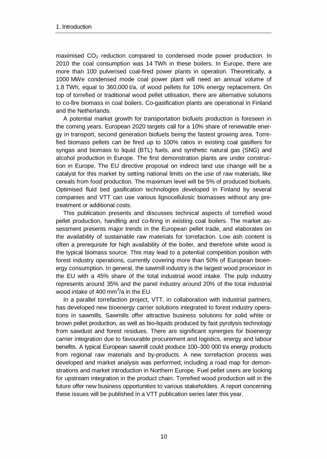
PrefaceThe research project “Torrefaction of woody and agro biomasses as energy carri-ers for the European markets” was carried out within the BioRefine programme ofTekes – the Finnish Funding Agency for Technology and Innovation during theyears 2010–2012. The project was coordinated by VTT.
This publication summarises the results of experimental work carried out withFinnish wood fuels at the pilot and laboratory scale concerning the production oftorrefied pellets, CFD simulation work on co-combustion with coal, determinationof safety-related indices and small-scale storage tests. A brief assessment of theEuropean market with a special emphasis on wood availability was carried out byPöyry Management Consulting Ltd. Five of the companies co-funding the publicnational torrefaction project conducted pilot-scale milling and co-firing tests inJapan with torrefied pellets and coal. The results have reported to the fundingparties in a confidential report.
The main objective of the project was to create a discussion platform for theFinnish industrial stakeholders involved in developing the torrefaction technologyor planning to include the torrefied biomass in their fuel supply for energy production.Thus, the steering group comprised representatives of the organisations and com-panies funding the research project: Marjatta Aarniala/Tekes, Jorma Isotalo/Pohjolan Voima Oy, Jukka Heiskanen/Fortum Power and Heat Oy, Matti Rautanen/Metso Oy, Markku Karlsson and Heikki Ilvespää/UPM-Kymmene Oy, Jukka Rou-hiainen/Helsingin Energia, Jaakko Soikkeli/Vapo Oy, Risto Joroinen/Metsä-Botnia Oy(later Metsä Fibre Oy), Kai Sipilä and Carl Wilén/VTT. Jorma Isotalo acted as chairof the steering group and Carl Wilén as secretary of the Torrefaction project in hisrole as project manager at VTT.
Major contributions to the project were made by Perttu Jukola/VTT (CFD simu-lation), Timo Järvinen/VTT (storage tests), Sampo Ratinen/VTT (fuel preparationfor pilot tests), Fred Verhoeff/ECN (pilot tests), Javier G. Torrent/Laboratorio OficialJ.M. Madariaga (dust explosion and ignition tests).
The authors would like to acknowledge all those who have participated and contrib-uted to the project as well as the steering group for active and fruitful participation.
Espoo, June 2013
6
ContentsAbstract ........................................................................................................... 3
Tiivistelmä ....................................................................................................... 4
Preface ............................................................................................................. 5
1. Introduction ............................................................................................... 9
2. Torrefaction ............................................................................................. 112.1 The process ..................................................................................... 112.2 Co-firing and grindability ................................................................... 122.3 Densification..................................................................................... 15
3. Commercial development ....................................................................... 163.1 Topell Energy ................................................................................... 173.2 Thermya ........................................................................................... 183.3 ANDRITZ torrefaction processes ....................................................... 193.4 Stramproy Green .............................................................................. 21
4. Pilot tests with Finnish wood fuels ......................................................... 224.1 General objectives ............................................................................ 224.2 Description of test programme .......................................................... 224.3 Test facilities .................................................................................... 23
4.3.1 Batch reactor ........................................................................... 234.3.2 Pronto-press ............................................................................ 244.3.3 Torrefaction pilot plant PATRIG ................................................ 244.3.4 Semi-industrial pelletising ......................................................... 25
4.4 Biomass feedstocks and preparation ................................................. 264.5 Results and discussion ..................................................................... 27
4.5.1 Small-scale tests ...................................................................... 274.5.2 Conclusions of the small-scale tests ......................................... 314.5.3 PATRIG production tests .......................................................... 314.5.4 Conclusions of PATRIG production runs ................................... 334.5.5 Comparison between small-scale tests and pilot-scale runs ....... 334.5.6 Semi-industrial pelletising tests ................................................. 34
4.6 Overall conclusions........................................................................... 34

7
5. CFD modelling of torrefied wood co-firing with coal in apulverised coal-fired furnace .................................................................. 365.1 Introduction ...................................................................................... 365.2 Modelling approach .......................................................................... 365.3 Furnace simulation ........................................................................... 375.4 Fuel properties and initial conditions .................................................. 375.5 Simulated cases ............................................................................... 385.6 Simulation results ............................................................................. 39
5.6.1 Combustion in general, temperature, heat transfer .................... 395.6.2 Burnout, unburned carbon and CO ........................................... 415.6.3 Simulated NOx emissions ......................................................... 435.6.4 Corrosion and fouling tendencies .............................................. 43
5.7 Conclusions...................................................................................... 44
6. Storage and handling properties of torrefied wood pellets .................... 456.1 Test procedures and materials .......................................................... 456.2 Results and discussion ..................................................................... 48
6.2.1 Bulk and energy density, durability............................................ 486.2.2 Climate tests ............................................................................ 49
6.3 Conclusions...................................................................................... 51
7. Safety-technical properties of torrefied wood ........................................ 537.1 Introduction ...................................................................................... 537.2 Tests and material ............................................................................ 53
7.2.1 Dust explosion test ................................................................... 537.2.2 Self-ignition and flammability tests ............................................ 55
7.3 Results ............................................................................................. 567.3.1 Explosion severity .................................................................... 567.3.2 Thermal stability ....................................................................... 57
7.4 IMO test for the transportation of dangerous goods ............................ 607.4.1 Test procedures ....................................................................... 607.4.2 Results and conclusions ........................................................... 61
7.5 Conclusions...................................................................................... 61
8. European market perspective ................................................................. 638.1 Market potential ................................................................................ 638.2 Woody biomass availability ............................................................... 64
9. Summary and conclusions ..................................................................... 68
References ..................................................................................................... 71


1. Introduction
9
1. Introduction
Physical and chemical properties of biomass can be modified by a torrefactionprocess closer to the properties of coal to replace large volumes of coal in existingpower plants and in coal gasifiers for syngas and transportation fuel production.Torrefaction is a thermochemical treatment of biomass at 200 to 300 °C, a clearlylower temperature range than in the classical charring process for coke produc-tion. It is carried out under atmospheric pressure and in the absence of oxygenand could be called a mild pyrolysis process. The main objective is to use torrefiedbiomass as a fuel, especially as a pellet, with similar grinding properties and stor-ability as coal, for co-firing in power plants. Many pilot- and demonstration-scaleplants are in operation in Europe and North America. However, full commercial-scale operation is still hampered by numerous technical constraints.
There is a growing interest in Finland and internationally to substitute fossil coalin power and heat production, given the potential for significant environmentalbenefits in terms of net CO2 emission reductions. Wood pellets are currently usedto replace coal in pulverised coal (PC)-fired boilers. Replacement shares varybetween 5 and 15%, due to physical and chemical properties of the wood fuels.The relatively low energy content and fibrous nature of the wood pellets limit thecombustion and pre-treatment in co-firing in existing PC boilers. The torrefied andpelletised biocoal product shows a large resemblance to coal. The higher volumetricenergy density as well as the brittle physical nature of the torrefied pellets allowshigher co-firing percentages, roughly up to 50% by mass, without major investmentsin modified handling and milling systems.
The market potential of torrefied biomass pellets is expected to be huge, con-sidering the substitution of coal in large-scale power and heat product. Replacingcoal on the market is strongly dependent on national and local feed-in tariffs.Without this support it will not be profitable to use torrefied biomass products,which typically may be twice as expensive as coal. The 2020 energy and climatestrategy will set national targets for renewable energy in Europe. For Finland,more than 38% of final energy will be produced from renewable sources. The lastremaining percentages are the most expensive ones. Often off-shore wind andbiomass co-firing in existing coal-fired power plants are price competitors. In Fin-land the 2020 targets will require a coal substitution of up to 7 TWh/a in sevenexisting coal-fired combined heat and power (CHP) boilers. The priority of nationalincentives has been given to CHP power plants with high overall efficiency and
1. Introduction
10
maximised CO2 reduction compared to condensed mode power production. In2010 the coal consumption was 14 TWh in these boilers. In Europe, there aremore than 100 pulverised coal-fired power plants in operation. Theoretically, a1000 MWe condensed mode coal power plant will need an annual volume of1.8 TWh, equal to 360,000 t/a, of wood pellets for 10% energy replacement. Ontop of torrefied or traditional wood pellet utilisation, there are alternative solutionsto co-fire biomass in coal boilers. Co-gasification plants are operational in Finlandand the Netherlands.
A potential market growth for transportation biofuels production is foreseen inthe coming years. European 2020 targets call for a 10% share of renewable ener-gy in transport, second generation biofuels being the fastest growing area. Torre-fied biomass pellets can be fired up to 100% ratios in existing coal gasifiers forsyngas and biomass to liquid (BTL) fuels, and synthetic natural gas (SNG) andalcohol production in Europe. The first demonstration plants are under construc-tion in Europe. The EU directive proposal on indirect land use change will be acatalyst for this market by setting national limits on the use of raw materials, likecereals from food production. The maximum level will be 5% of produced biofuels.Optimised fluid bed gasification technologies developed in Finland by severalcompanies and VTT can use various lignocellulosic biomasses without any pre-treatment or additional costs.
This publication presents and discusses technical aspects of torrefied woodpellet production, handling and co-firing in existing coal boilers. The market as-sessment presents major trends in the European pellet trade, and elaborates onthe availability of sustainable raw materials for torrefaction. Low ash content isoften a prerequisite for high availability of the boiler, and therefore white wood isthe typical biomass source. This may lead to a potential competition position withforest industry operations, currently covering more than 50% of European bioen-ergy consumption. In general, the sawmill industry is the largest wood processor inthe EU with a 45% share of the total industrial wood intake. The pulp industryrepresents around 35% and the panel industry around 20% of the total industrialwood intake of 400 mm3/a in the EU.
In a parallel torrefaction project, VTT, in collaboration with industrial partners,has developed new bioenergy carrier solutions integrated to forest industry opera-tions in sawmills. Sawmills offer attractive business solutions for solid white orbrown pellet production, as well as bio-liquids produced by fast pyrolysis technologyfrom sawdust and forest residues. There are significant synergies for bioenergycarrier integration due to favourable procurement and logistics, energy and labourbenefits. A typical European sawmill could produce 100–300 000 t/a energy productsfrom regional raw materials and by-products. A new torrefaction process wasdeveloped and market analysis was performed, including a road map for demon-strations and market introduction in Northern Europe. Fuel pellet users are lookingfor upstream integration in the product chain. Torrefied wood production will in thefuture offer new business opportunities to various stakeholders. A report concerningthese issues will be published in a VTT publication series later this year.
2. Torrefaction
11
2. Torrefaction
2.1 The process
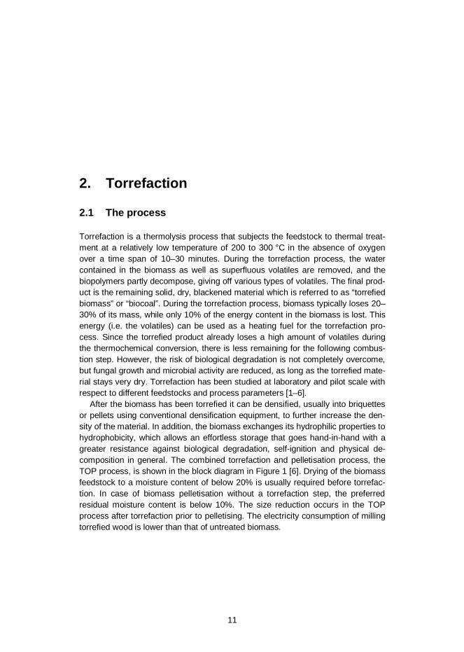
Torrefaction is a thermolysis process that subjects the feedstock to thermal treat-ment at a relatively low temperature of 200 to 300 °C in the absence of oxygenover a time span of 10–30 minutes. During the torrefaction process, the watercontained in the biomass as well as superfluous volatiles are removed, and thebiopolymers partly decompose, giving off various types of volatiles. The final prod-uct is the remaining solid, dry, blackened material which is referred to as “torrefiedbiomass” or “biocoal”. During the torrefaction process, biomass typically loses 20–30% of its mass, while only 10% of the energy content in the biomass is lost. Thisenergy (i.e. the volatiles) can be used as a heating fuel for the torrefaction pro-cess. Since the torrefied product already loses a high amount of volatiles duringthe thermochemical conversion, there is less remaining for the following combus-tion step. However, the risk of biological degradation is not completely overcome,but fungal growth and microbial activity are reduced, as long as the torrefied mate-rial stays very dry. Torrefaction has been studied at laboratory and pilot scale withrespect to different feedstocks and process parameters [1–6].
After the biomass has been torrefied it can be densified, usually into briquettesor pellets using conventional densification equipment, to further increase the den-sity of the material. In addition, the biomass exchanges its hydrophilic properties tohydrophobicity, which allows an effortless storage that goes hand-in-hand with agreater resistance against biological degradation, self-ignition and physical de-composition in general. The combined torrefaction and pelletisation process, theTOP process, is shown in the block diagram in Figure 1 [6]. Drying of the biomassfeedstock to a moisture content of below 20% is usually required before torrefac-tion. In case of biomass pelletisation without a torrefaction step, the preferredresidual moisture content is below 10%. The size reduction occurs in the TOPprocess after torrefaction prior to pelletising. The electricity consumption of millingtorrefied wood is lower than that of untreated biomass.

2. Torrefaction
12
Figure 1. Pelletisation, torrefaction and TOP process schemes [6].
The primary goal in torrefaction is to refine raw biomass to an upgraded solid fuel,including better handling qualities and enhanced combustible properties similar tothose of fossil coal, leading to decreased costs. The essential principle in thisrespect is to increase the energy density of the biomass (roughly 30%), requiring agrowth of the ratio between energy and mass. Consequently, the calorific value oftorrefied biomass increases as well. During the process, the structure of biomasschanges, leading to new properties that make the handling of the final productmuch easier and also offers the possibility to utilise it in existing coal-fired boilers.
2.2 Co-firing and grindability
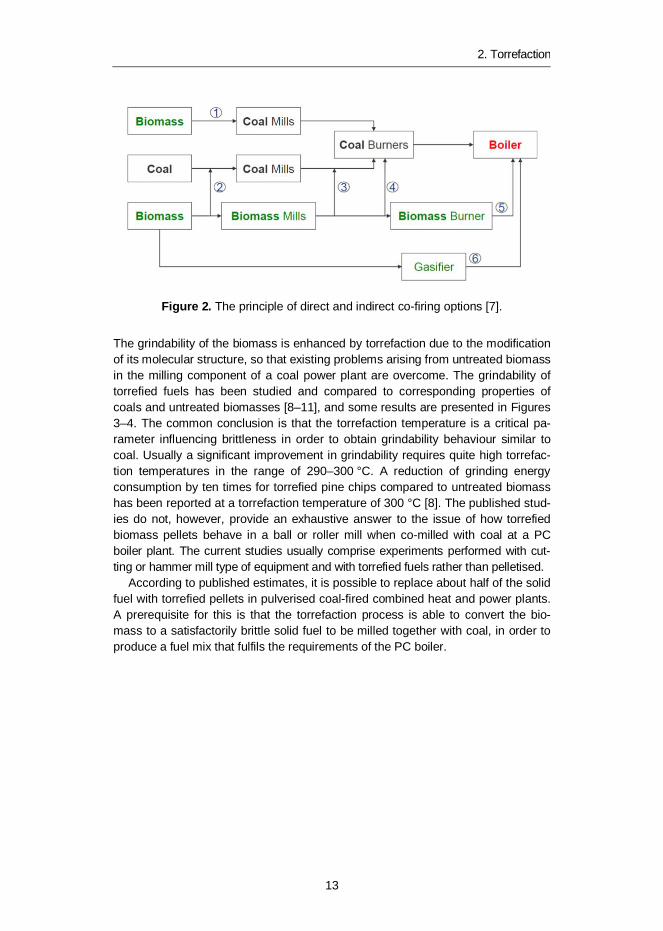
There are several options to introduce biomass co-firing in a coal-fired PC boilerplant, as described in Figure 2 [7]. Pathway 2, pre-mixing biomass (wood pellets)with coal and milling and firing the mixed fuel through the existing coal firing sys-tem, is done at a small number of power plants in Europe. The co-firing ratios aremodest, generally less than 10% on a heat input basis [7]. Significantly higherratios are expected when co-firing brittle torrefied biomass pellets due to theirbetter grindability in the coal mills.
2. Torrefaction
13
Figure 2. The principle of direct and indirect co-firing options [7].
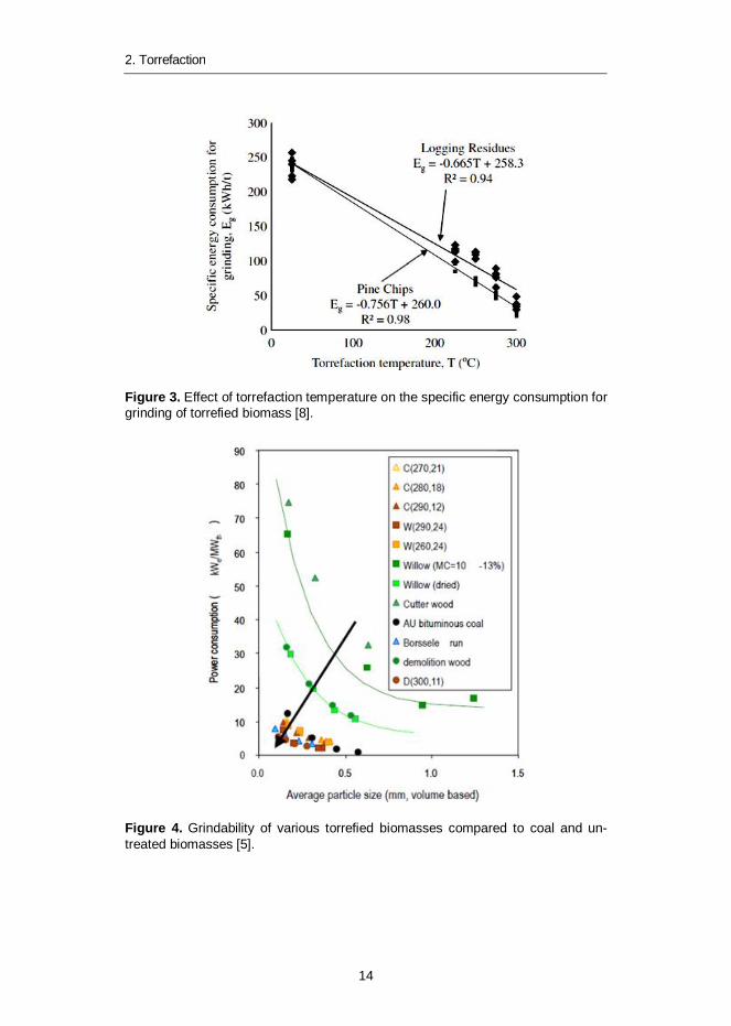
The grindability of the biomass is enhanced by torrefaction due to the modificationof its molecular structure, so that existing problems arising from untreated biomassin the milling component of a coal power plant are overcome. The grindability oftorrefied fuels has been studied and compared to corresponding properties ofcoals and untreated biomasses [8–11], and some results are presented in Figures3–4. The common conclusion is that the torrefaction temperature is a critical pa-rameter influencing brittleness in order to obtain grindability behaviour similar tocoal. Usually a significant improvement in grindability requires quite high torrefac-tion temperatures in the range of 290–300 °C. A reduction of grinding energyconsumption by ten times for torrefied pine chips compared to untreated biomasshas been reported at a torrefaction temperature of 300 °C [8]. The published stud-ies do not, however, provide an exhaustive answer to the issue of how torrefiedbiomass pellets behave in a ball or roller mill when co-milled with coal at a PCboiler plant. The current studies usually comprise experiments performed with cut-ting or hammer mill type of equipment and with torrefied fuels rather than pelletised.
According to published estimates, it is possible to replace about half of the solidfuel with torrefied pellets in pulverised coal-fired combined heat and power plants.A prerequisite for this is that the torrefaction process is able to convert the bio-mass to a satisfactorily brittle solid fuel to be milled together with coal, in order toproduce a fuel mix that fulfils the requirements of the PC boiler.
2. Torrefaction
14
Figure 3. Effect of torrefaction temperature on the specific energy consumption forgrinding of torrefied biomass [8].
Figure 4. Grindability of various torrefied biomasses compared to coal and un-treated biomasses [5].

2. Torrefaction
15
2.3 Densification
Product densification allows torrefied biomass to be converted into a convenientenergy carrier in terms of transportation, storage and handling, due to its uniformshape and size. The pelletisation process of woody biomasses is a commercialprocess, and the current global market volume of the wood pellet market is esti-mated to be about 16 Mt/a. The fundamentals of biomass pelletising have beenstudied with the aim of understanding the phenomena involved in densification[12–13]. The practical experience from the pelletisation of torrefied biomasses isstill quite limited, but research and pilot-scale experiments are ongoing [14].
Besides pelletisation, producing larger size densified fuel chunks by briquettingis also possible. The briquettes are typically cylindrical pieces with a diameter of50 to 80 mm, compared to the usual pellet diameter of 6–10 mm. Briquetting ismostly used for smaller-scale production schemes, as the capacity of a briquettingpress is 1–3 t/h. Modern pellet plants may have an annual capacity of 500,000 t/aand the capacity of individual pellet presses is in excess of 5 t/h.
3. Commercial development
16
3. Commercial development
Commercial development of torrefaction is currently in its early phase. Severaltechnology companies and their industrial partners are moving towards commer-cial market introduction. The current demand for torrefied biomass of utilities aloneexceeds the production capacity that can be realised in the coming years by far.This puts a lot of pressure on the torrefaction developers, who need to scale uptheir technologies as soon as possible.
An overview of reactor technologies that are applied for torrefaction is present-ed in Table 1. All reactor technologies here are “proven technology” in other appli-cations, such as combustion, drying or gasification [1]. Several torrefaction tech-nology providers in Europe claim that they have reached commercial production.In North America there are also some interesting initiatives under development,which claim that they are in a commercial demonstration phase. A few shiploadsof torrefied pellets have been reported to have been shipped to Europe by the UScompany New Biomass Energy. The company’s 80,000 t/a plant in Quitman, Mis-sissippi is currently being expanded to over 150,000 t/a. The market is expected tomove forward but the available public information is very limited, especially con-cerning the technologies used and volumes produced.
The current general view is that most of the demonstration plants have tech-nical problems that have delayed their commercial operation. Several smaller pilotinstallations covering a wide range of different technologies are available at researchinstitutes and universities, such as Energy research Centre of the Netherlands(ECN), the Spanish National Renewable Energy Centre (CENER) and BioEndev(Sweden). A few of the most advanced projects are briefly described in Table 1.

3. Commercial development
17
Table 1. Overview of reactor technologies and associated suppliers [1].
Reactor technologies Torrefaction supplierRotary drum reactor CDS (UK), Torr-Coal (NL), Bio3D(FR), EBES AG (AT),
4 Energy Invest (BE), Bioendev/ETPC (SWE), AtmosclearS.A.(CH)
Screw conveyor reactor BTG (NL), Biolake (NL), Foxcoal (NL), Agri-tech producers (US)
Multiple Hearth Furnace(MHF)/TurboDryer
CMI-NESA (BE), Wyssmont (US)
TORBED reactor Topell (NL)
Microwave reactor Rotavawe (UK)
Compact moving bed ECN (NL), Thermya (FR), Buhler (US)
(Oscillating) Belt conveyor Stramproy Green investment (NL),New Earth Eco Technology (US)
3.1 Topell Energy
Topell Energy applies a TORBED reactor designed for effective gas/solid contactin various industrial applications. Topell started the construction of their first com-mercial torrefaction plant in Duiven, the Netherlands, in 2010. With a productioncapacity of 60,000 t/a, the plant was expected to start producing torrefied fuelpellets from biomass in early 2011 [15]. Some 7–10,000 t of torrefied biomass hasbeen produced for milling and co-combustion tests for various customers. Theplant is still in the commissioning phase and a new combustion unit will be opera-tional in mid-2013.
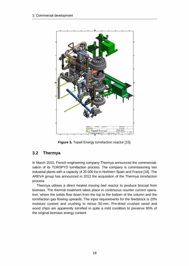
The TORBED fluidised bed reactor, Figure 5, has a short retention time andhigh heat transfer efficiency. However, it requires a fairly small particle size (saw-dust), contrary to moving bed reactors, which can accept normal-sized woodchips. This set additional requirements on the pre-treatment steps of biomassfuels. Topell standard feedstock originates from forestry residues and biomassfrom landscaping.
3. Commercial development
18
Figure 5. Topell Energy torrefaction reactor [15].
3.2 Thermya
In March 2010, French engineering company Thermya announced the commerciali-sation of its TORSPYD torrefaction process. The company is commissioning twoindustrial plants with a capacity of 20 000 t/a in Northern Spain and France [16]. TheAREVA group has announced in 2012 the acquisition of the Thermya torrefactionprocess.
Thermya utilises a direct heated moving bed reactor to produce biocoal frombiomass. The thermal treatment takes place in continuous counter current opera-tion, where the solids flow down from the top to the bottom of the column and thetorrefaction gas flowing upwards. The input requirements for the feedstock is 20%moisture content and crushing to minus 50 mm. Pre-dried crushed wood andwood chips are apparently torrefied in quite a mild condition to preserve 95% ofthe original biomass energy content.
3. Commercial development
19
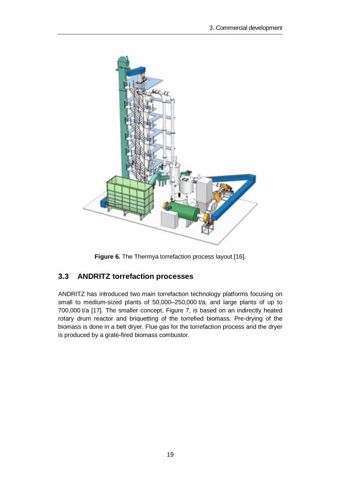
Figure 6. The Thermya torrefaction process layout [16].
3.3 ANDRITZ torrefaction processes
ANDRITZ has introduced two main torrefaction technology platforms focusing onsmall to medium-sized plants of 50,000–250,000 t/a, and large plants of up to700,000 t/a [17]. The smaller concept, Figure 7, is based on an indirectly heatedrotary drum reactor and briquetting of the torrefied biomass. Pre-drying of thebiomass is done in a belt dryer. Flue gas for the torrefaction process and the dryeris produced by a grate-fired biomass combustor.
3. Commercial development
20
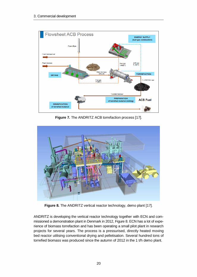
Figure 7. The ANDRITZ ACB torrefaction process [17].
Figure 8. The ANDRITZ vertical reactor technology, demo plant [17].
ANDRITZ is developing the vertical reactor technology together with ECN and com-missioned a demonstration plant in Denmark in 2012, Figure 8. ECN has a lot of expe-rience of biomass torrefaction and has been operating a small pilot plant in researchprojects for several years. The process is a pressurised, directly heated movingbed reactor utilising conventional drying and pelletisation. Several hundred tons oftorrefied biomass was produced since the autumn of 2012 in the 1 t/h demo plant.
3. Commercial development
21
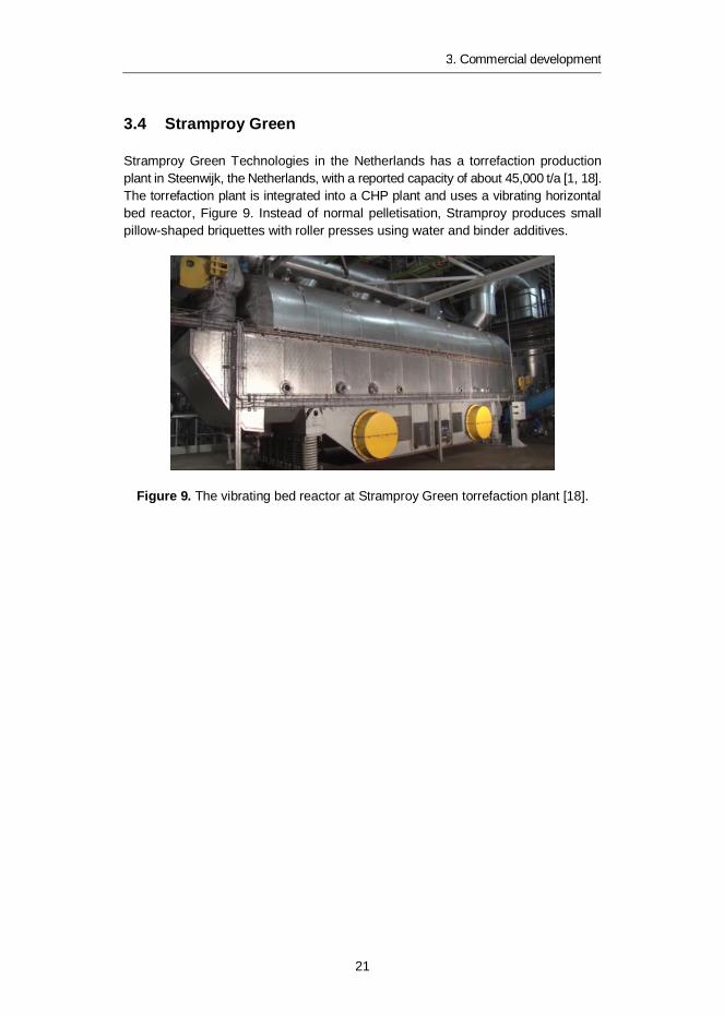
3.4 Stramproy Green
Stramproy Green Technologies in the Netherlands has a torrefaction productionplant in Steenwijk, the Netherlands, with a reported capacity of about 45,000 t/a [1, 18].The torrefaction plant is integrated into a CHP plant and uses a vibrating horizontalbed reactor, Figure 9. Instead of normal pelletisation, Stramproy produces smallpillow-shaped briquettes with roller presses using water and binder additives.
Figure 9. The vibrating bed reactor at Stramproy Green torrefaction plant [18].
4. Pilot tests with Finnish wood fuels
22
4. Pilot tests with Finnish wood fuels
4.1 General objectives
Given the availability of torrefaction pilot facilities in Europe, it was decided in theplanning phase of the concerned national torrefaction research project not to buildand operate separate pilot equipment. At this stage it was considered more effi-cient to use the available knowledge and experience in testing various Finnishfeedstocks for torrefaction. The primary aims were to have a good understandingof the behaviour of the selected wood fuels in torrefaction, to produce largeenough quantities for further testing, and to transfer the available public know-howin the torrefaction community to the project partners. ECN was identified early onas the most suitable project partner having the required laboratory and pilot facili-ties, and a good deal of experience in torrefaction research work. ECN was thusgranted the order to execute a test programme with Finnish wood fuels, whichincluded preliminary laboratory-scale testing and pilot-scale test runs in thePATRIG torrefaction test rig. The description of tests, results and conclusions inthe following sections is mainly based on the test report produced by ECN [19].
4.2 Description of test programme
A set of five wood fuels was chosen for preliminary laboratory -scale testing atECN. The torrefaction behaviour was tested by means of Thermo-GravimetricAnalysis (TGA) and ECN’s torrefaction batch reactor. The pelletising behaviour ofthe wood fuels was tested in a small-scale, single pellet Pronto-press. Based onthese findings, two wood fuels were selected and torrefied in the PATRIG pilot-scale torrefaction plant at ECN, to produce several tonnes of materials undervarious torrefaction conditions. With the materials produced, pelletising tests wereexecuted at the semi-industrial pelletising laboratory of CPM-Europe in Amsterdam.
TGA and batch tests were carried out for the five feedstocks to determine thetorrefaction behaviour of the biomass, comprising:
TGA tests at different torrefaction temperatures to determine the preferredtorrefaction temperature for the batch tests.
4. Pilot tests with Finnish wood fuels
23
Five batch tests to produce small portions of torrefied materials from thematerials and to determine the operating settings for the two materials tobe processed in the PATRIG pilot rig.
Determination of the mass and energy balance for the five batch tests, in-cluding proximate and ultimate analyses of the raw and torrefied materials.
Small-scale Pronto-press tests with the torrefied materials produced in thebatch reactor.
The pilot test programme comprised operation of the PATRIG pilot-scale torrefac-tion plant over two weeks, each week comprising approximately 75 hours on a 24-hour basis. Two wood fuels were selected for the pilot tests, including good qualitywood chips produced from thinnings and crushed forest residue containing morebark and needles. Based on the results of the TGA, batch and Pronto-press tests,three operating temperatures were selected: 235, 245 and 255 °C. Semi-industrialscale pelletising tests were carried out with the materials produced in the PATRIGtest rig. In total about 4300 kg of torrefied wood and forest residue chips wereproduced. Of this, about 1,500 kg of torrefied pellets were produced at CPM.
4.3 Test facilities
4.3.1 Batch reactor
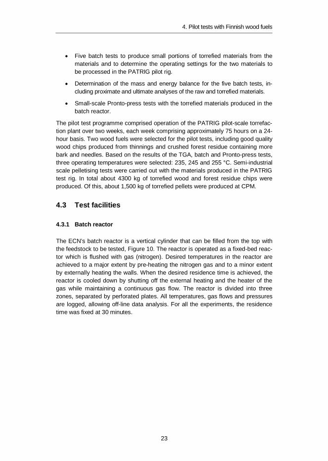
The ECN’s batch reactor is a vertical cylinder that can be filled from the top withthe feedstock to be tested, Figure 10. The reactor is operated as a fixed-bed reac-tor which is flushed with gas (nitrogen). Desired temperatures in the reactor areachieved to a major extent by pre-heating the nitrogen gas and to a minor extentby externally heating the walls. When the desired residence time is achieved, thereactor is cooled down by shutting off the external heating and the heater of thegas while maintaining a continuous gas flow. The reactor is divided into threezones, separated by perforated plates. All temperatures, gas flows and pressuresare logged, allowing off-line data analysis. For all the experiments, the residencetime was fixed at 30 minutes.
4. Pilot tests with Finnish wood fuels
24
Figure 10. The batch reactor at ECN.
4.3.2 Pronto-press
In the ECN’s Pronto-press, a single pellet is made under accurately controlledtemperature and pressure conditions. The press is filled with a small amount ofmaterial, which is compressed. The density of the single pellet produced gives anindication of how well the material can be pelletised.
4.3.3 Torrefaction pilot plant PATRIG
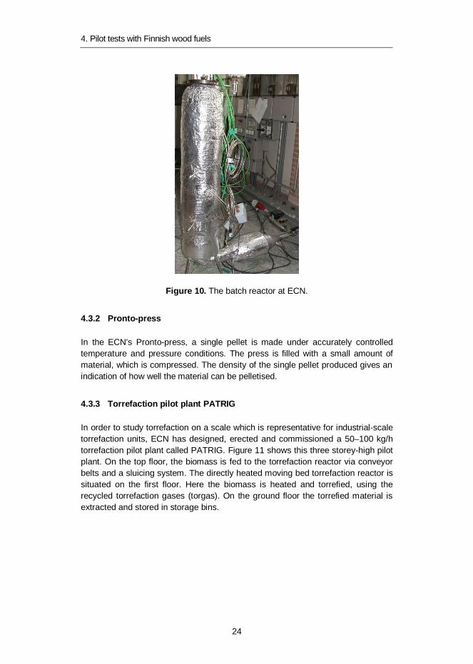
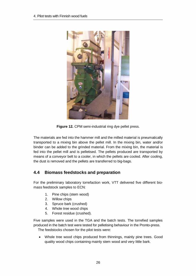
In order to study torrefaction on a scale which is representative for industrial-scaletorrefaction units, ECN has designed, erected and commissioned a 50–100 kg/htorrefaction pilot plant called PATRIG. Figure 11 shows this three storey-high pilotplant. On the top floor, the biomass is fed to the torrefaction reactor via conveyorbelts and a sluicing system. The directly heated moving bed torrefaction reactor issituated on the first floor. Here the biomass is heated and torrefied, using therecycled torrefaction gases (torgas). On the ground floor the torrefied material isextracted and stored in storage bins.
4. Pilot tests with Finnish wood fuels
25
Figure 11. Overview of ECN’s 50–100 kg/h torrefaction pilot plant PATRIG.
4.3.4 Semi-industrial pelletising
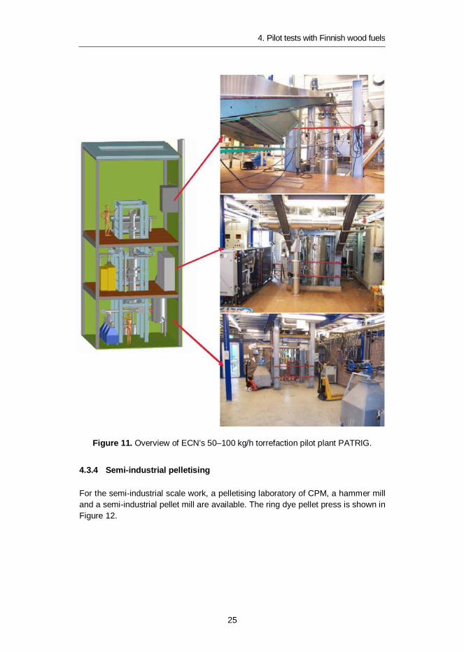
For the semi-industrial scale work, a pelletising laboratory of CPM, a hammer milland a semi-industrial pellet mill are available. The ring dye pellet press is shown inFigure 12.
4. Pilot tests with Finnish wood fuels
26
Figure 12. CPM semi-industrial ring dye pellet press.
The materials are fed into the hammer mill and the milled material is pneumaticallytransported to a mixing bin above the pellet mill. In the mixing bin, water and/orbinder can be added to the grinded material. From the mixing bin, the material isfed into the pellet mill and is pelletised. The pellets produced are transported bymeans of a conveyor belt to a cooler, in which the pellets are cooled. After cooling,the dust is removed and the pellets are transferred to big-bags.
4.4 Biomass feedstocks and preparation
For the preliminary laboratory torrefaction work, VTT delivered five different bio-mass feedstock samples to ECN:
1. Pine chips (stem wood)2. Willow chips3. Spruce bark (crushed)4. Whole tree wood chips5. Forest residue (crushed).
Five samples were used in the TGA and the batch tests. The torrefied samplesproduced in the batch test were tested for pelletising behaviour in the Pronto-press.
The feedstocks chosen for the pilot tests were:
Whole tree wood chips produced from thinnings, mainly pine trees. Goodquality wood chips containing mainly stem wood and very little bark.
4. Pilot tests with Finnish wood fuels
27
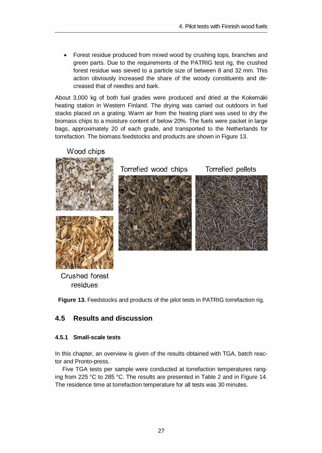
Forest residue produced from mixed wood by crushing tops, branches andgreen parts. Due to the requirements of the PATRIG test rig, the crushedforest residue was sieved to a particle size of between 8 and 32 mm. Thisaction obviously increased the share of the woody constituents and de-creased that of needles and bark.
About 3,000 kg of both fuel grades were produced and dried at the Kokemäkiheating station in Western Finland. The drying was carried out outdoors in fuelstacks placed on a grating. Warm air from the heating plant was used to dry thebiomass chips to a moisture content of below 20%. The fuels were packet in largebags, approximately 20 of each grade, and transported to the Netherlands fortorrefaction. The biomass feedstocks and products are shown in Figure 13.
Figure 13. Feedstocks and products of the pilot tests in PATRIG torrefaction rig.
4.5 Results and discussion
4.5.1 Small-scale tests
In this chapter, an overview is given of the results obtained with TGA, batch reac-tor and Pronto-press.
Five TGA tests per sample were conducted at torrefaction temperatures rang-ing from 225 °C to 285 °C. The results are presented in Table 2 and in Figure 14.The residence time at torrefaction temperature for all tests was 30 minutes.

4. Pilot tests with Finnish wood fuels
28
Table 2. TGA results for the biomass samples.
Test no Temperature(°C)
Mass yield (wt% dry basis)Forestresidue
Wholetree
Sprucebark
Pinechips
Willowchips
1 225 93.78 93.53 91.41 94.53 93.47
2 240 89.80 88.62 87.91 91.20 88.17
3 255 84.13 82.01 83.68 85.93 81.64
4 270 77.10 74.38 78.34 78.36 74.72
5 285 68.50 65.27 72.03 67.88 65.88
Figure 14. Degradation curves for the biomass samples.
Previous investigations showed that between 15–20 wt% is the optimum massloss for torrefaction of dry woody materials, assuming that the hemicellulosescontent of the materials is approximately 20 wt%. Figure 14 shows that the differencesbetween the five biomass samples tested are relatively small and that 15–20% massloss is realised for all materials at a temperature of between 250 and 260 °C.Therefore, from the TGA results 250–260 °C was found to be the optimum torre-faction temperature range for all the materials.
Based on the TGA results, batch reactor experiments with five biomass sam-ples were carried out at three selected temperature levels:
for whole tree chips: 235, 245 and 255 °C for forest residue chips: 245 and 255 °C for willow chips, crushed bark and pine chips: 255 °C.
The torrefaction temperatures for forest residue and whole tree chips were chosenat the lower end of the torrefaction regime, because experience showed thatpelletising mildly torrefied material is easier than pelletising severely torrefiedmaterial.
4. Pilot tests with Finnish wood fuels
29
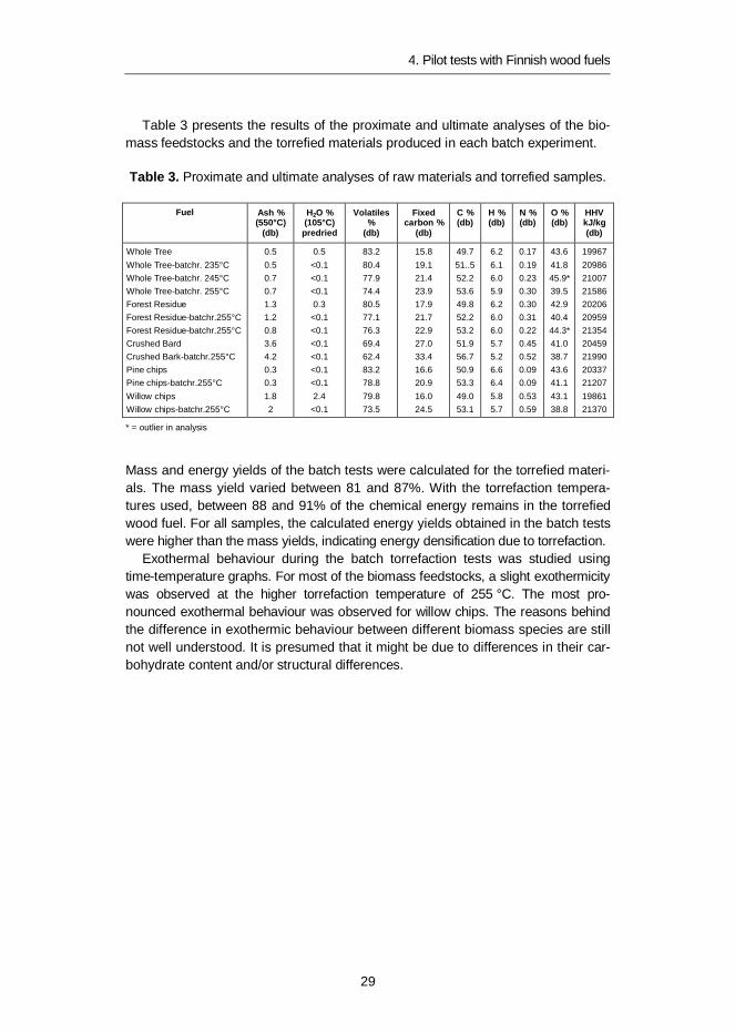
Table 3 presents the results of the proximate and ultimate analyses of the bio-mass feedstocks and the torrefied materials produced in each batch experiment.
Table 3. Proximate and ultimate analyses of raw materials and torrefied samples.
Fuel Ash %(550°C)
(db)
H2O %(105°C)
predried
Volatiles%
(db)
Fixedcarbon %
(db)
C %(db)
H %(db)
N %(db)
O %(db)
HHVkJ/kg(db)
Whole TreeWhole Tree-batchr. 235°CWhole Tree-batchr. 245°CWhole Tree-batchr. 255°CForest ResidueForest Residue-batchr.255°CForest Residue-batchr.255°CCrushed BardCrushed Bark-batchr.255°CPine chipsPine chips-batchr.255°CWillow chipsWillow chips-batchr.255°C
0.50.50.70.71.31.20.83.64.20.30.31.82
0.5<0.1<0.1<0.10.3
<0.1<0.1<0.1<0.1<0.1<0.12.4
<0.1
83.280.477.974.480.577.176.369.462.483.278.879.873.5
15.819.121.423.917.921.722.927.033.416.620.916.024.5
49.751..552.253.649.852.253.251.956.750.953.349.053.1
6.26.16.05.96.26.06.05.75.26.66.45.85.7
0.170.190.230.300.300.310.220.450.520.090.090.530.59
43.641.845.9*39.542.940.444.3*41.038.743.641.143.138.8
19967209862100721586202062095921354204592199020337212071986121370
* = outlier in analysis
Mass and energy yields of the batch tests were calculated for the torrefied materi-als. The mass yield varied between 81 and 87%. With the torrefaction tempera-tures used, between 88 and 91% of the chemical energy remains in the torrefiedwood fuel. For all samples, the calculated energy yields obtained in the batch testswere higher than the mass yields, indicating energy densification due to torrefaction.
Exothermal behaviour during the batch torrefaction tests was studied usingtime-temperature graphs. For most of the biomass feedstocks, a slight exothermicitywas observed at the higher torrefaction temperature of 255 °C. The most pro-nounced exothermal behaviour was observed for willow chips. The reasons behindthe difference in exothermic behaviour between different biomass species are stillnot well understood. It is presumed that it might be due to differences in their car-bohydrate content and/or structural differences.

4. Pilot tests with Finnish wood fuels
30
Figure 15. Time-temperature graph for willow chips at set point 255 °C. An over-shoot of the recorded temperatures can be observed, indicating an exothermicbehaviour.
In order to have an indication of the pelletising behaviour of the torrefied materials,single pellet Pronto-press tests were executed to see if there is a chance that thetorrefied materials can be pelletised on an industrial scale. Based on these small-scale Pronto-press tests, final decisions were taken on the torrefaction tempera-ture level in the PATRIG pilot plant. The torrefaction temperature influences thepellet quality and by determining the pelletising behaviour before the execution ofthe PATRIG run, one can choose a temperature level in PATRIG that gives thebest chance of good quality pellets.
In the Pronto-press, a single pellet is made under controlled conditions. Thetemperature and pressure are chosen at a level comparable with the levels in anindustrial pellet mill. The duration of pressing is one minute, this being much long-er than in a pellet mill. The density of the single pellet produced gives an indicationof how well the material can be pelletised. The results are summarised belowregarding prediction for pelletising:
Whole tree chips 235oC possible Whole tree chips 245oC difficult Whole tree chips 255oC more difficult Forest residue 245oC large uncertainty, no prediction Forest residue 255oC difficult Willow chips 255oC difficult Crushed bark 255oC impossible Pine chips 255oC difficult.
Based on the results, it was concluded that neither torrefied whole tree chips norforest residue chips are easy to pelletise, but that the chance of getting good pel-lets increases when the torrefaction temperature is low. Therefore, the torrefaction

4. Pilot tests with Finnish wood fuels
31
temperature during the PATRIG runs was chosen to be as low as practical. Theselow temperatures are also favourable to the prevention of excessive exothermicreactions.
4.5.2 Conclusions of the small-scale tests
For the results of all small-scale tests, the following conclusions can be drawn:
The optimum torrefaction temperature range for whole tree chips, forestresidue, spruce bark and pine chips is estimated to be 250–260 °C.
Torrefied materials have a higher energy density than the raw materials.This is explained by the higher loss in mass than in energy. At the estimatedoptimum torrefaction temperature, the energy yields are higher than 87%.
Whole tree chips, spruce bark and willow chips are slightly exothermal.Forest residue and pine chips are hardly exothermal. For willow chips aslightly lower torrefaction temperature should be applied to avoid exother-mic reactions that might lead to a temperature rise during the torrefactionprocess. For pine chips, a higher temperature can be applied.
The chance of getting good pellets increases when the torrefaction tem-perature is low.
Based on these results, it is expected that both forest residue and whole tree chipscan be torrefied in PATRIG without a significant temperature increase, but thatpelletising these materials will not be a straightforward process. Especially athigher torrefaction temperatures, pelletising could be difficult. Therefore, relativelylow torrefaction temperatures will be chosen for the PATRIG runs. Semi-industrialscale tests will show the pelletising possibilities.
4.5.3 PATRIG production tests
The purpose of the PATRIG test runs was to produce torrefied materials for pellet-ising tests and to deliver the produced pellets and the remaining torrefied materi-als to VTT for further testing in Finland. In this section, the findings during thePATRIG production runs are reported.
The pilot testing started with the good quality whole tree wood chips. Based onthe results of the TGA, batch and Pronto-press tests, three operating temperatureswere selected: 235, 245 and 255 °C. It was soon observed that the set point of235 °C (torgas inlet temperature) was very low and the tests were continued athigher temperatures. The total duration of the run was 68.7 hours. Little or noexothermicity was found at these temperatures. The whole tree chips productionrun went smoothly.
4. Pilot tests with Finnish wood fuels
32
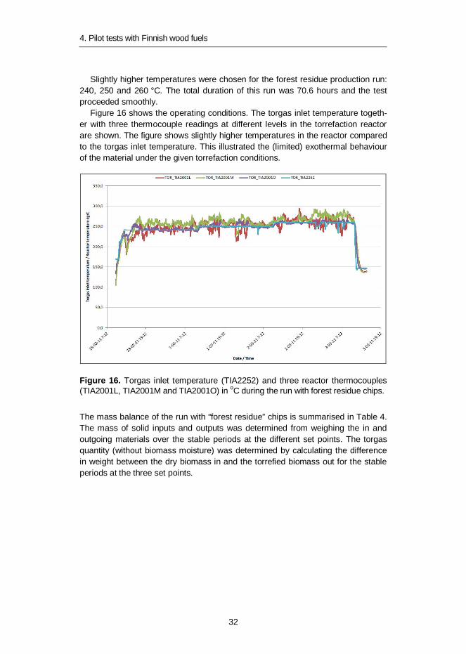
Slightly higher temperatures were chosen for the forest residue production run:240, 250 and 260 °C. The total duration of this run was 70.6 hours and the testproceeded smoothly.
Figure 16 shows the operating conditions. The torgas inlet temperature togeth-er with three thermocouple readings at different levels in the torrefaction reactorare shown. The figure shows slightly higher temperatures in the reactor comparedto the torgas inlet temperature. This illustrated the (limited) exothermal behaviourof the material under the given torrefaction conditions.
Figure 16. Torgas inlet temperature (TIA2252) and three reactor thermocouples(TIA2001L, TIA2001M and TIA2001O) in oC during the run with forest residue chips.
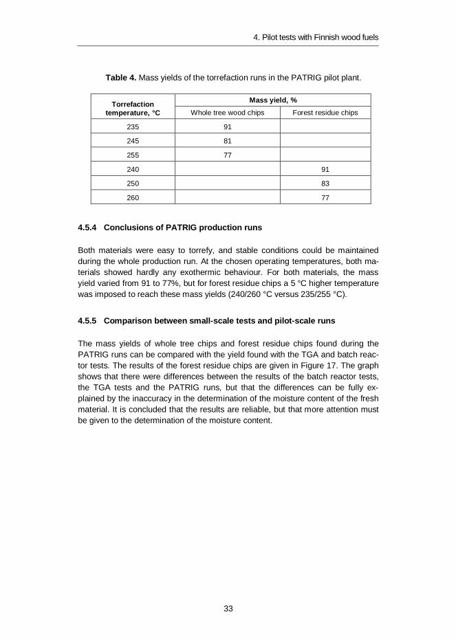
The mass balance of the run with “forest residue” chips is summarised in Table 4.The mass of solid inputs and outputs was determined from weighing the in andoutgoing materials over the stable periods at the different set points. The torgasquantity (without biomass moisture) was determined by calculating the differencein weight between the dry biomass in and the torrefied biomass out for the stableperiods at the three set points.
4. Pilot tests with Finnish wood fuels
33
Table 4. Mass yields of the torrefaction runs in the PATRIG pilot plant.
Torrefactiontemperature, °C
Mass yield, %Whole tree wood chips Forest residue chips
235 91
245 81
255 77
240 91
250 83
260 77
4.5.4 Conclusions of PATRIG production runs
Both materials were easy to torrefy, and stable conditions could be maintainedduring the whole production run. At the chosen operating temperatures, both ma-terials showed hardly any exothermic behaviour. For both materials, the massyield varied from 91 to 77%, but for forest residue chips a 5 °C higher temperaturewas imposed to reach these mass yields (240/260 °C versus 235/255 °C).
4.5.5 Comparison between small-scale tests and pilot-scale runs
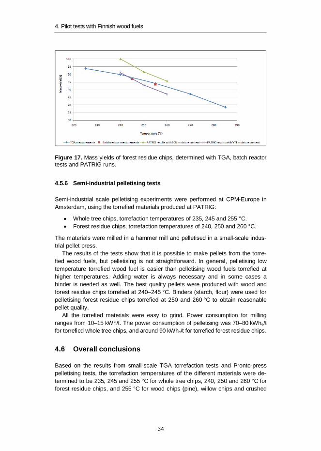
The mass yields of whole tree chips and forest residue chips found during thePATRIG runs can be compared with the yield found with the TGA and batch reac-tor tests. The results of the forest residue chips are given in Figure 17. The graphshows that there were differences between the results of the batch reactor tests,the TGA tests and the PATRIG runs, but that the differences can be fully ex-plained by the inaccuracy in the determination of the moisture content of the freshmaterial. It is concluded that the results are reliable, but that more attention mustbe given to the determination of the moisture content.
4. Pilot tests with Finnish wood fuels
34
Figure 17. Mass yields of forest residue chips, determined with TGA, batch reactortests and PATRIG runs.
4.5.6 Semi-industrial pelletising tests
Semi-industrial scale pelletising experiments were performed at CPM-Europe inAmsterdam, using the torrefied materials produced at PATRIG:
Whole tree chips, torrefaction temperatures of 235, 245 and 255 °C. Forest residue chips, torrefaction temperatures of 240, 250 and 260 °C.
The materials were milled in a hammer mill and pelletised in a small-scale indus-trial pellet press.
The results of the tests show that it is possible to make pellets from the torre-fied wood fuels, but pelletising is not straightforward. In general, pelletising lowtemperature torrefied wood fuel is easier than pelletising wood fuels torrefied athigher temperatures. Adding water is always necessary and in some cases abinder is needed as well. The best quality pellets were produced with wood andforest residue chips torrefied at 240–245 °C. Binders (starch, flour) were used forpelletising forest residue chips torrefied at 250 and 260 °C to obtain reasonablepellet quality.
All the torrefied materials were easy to grind. Power consumption for millingranges from 10–15 kWh/t. The power consumption of pelletising was 70–80 kWhe/tfor torrefied whole tree chips, and around 90 kWhe/t for torrefied forest residue chips.
4.6 Overall conclusions
Based on the results from small-scale TGA torrefaction tests and Pronto-presspelletising tests, the torrefaction temperatures of the different materials were de-termined to be 235, 245 and 255 °C for whole tree chips, 240, 250 and 260 °C forforest residue chips, and 255 °C for wood chips (pine), willow chips and crushed

4. Pilot tests with Finnish wood fuels
35
bark (spruce). Batch reactor tests and PATRIG production runs confirmed thatwith the torrefaction temperatures mentioned, good quality torrefied materials wereproduced, except for whole tree chips torrefied at 235 °C. Here the torrefactiontemperature was too low. Further, it was confirmed on a semi-industrial scale thatgood pellets can be produced from these materials except for torrefied forest resi-due chips torrefied at 260 °C. Overall it can be concluded that torrefied whole treechips and forest residue chips can be pelletised, provided that the torrefactiontemperature is no higher than 250 °C.
5. CFD modelling of torrefied wood co-firing with coal in a pulverised coal-fired furnace
36
5. CFD modelling of torrefied wood co-firingwith coal in a pulverised coal-fired furnace
5.1 Introduction
Computational Fluid Dynamics (CFD) was applied to simulate the co-firing of torre-fied wood biomass (TF) with coal in a (normally) pulverised coal-fired furnace [20].The goal of the work was to investigate the feasibility of the above-mentioned fuelsto replace part of the coal from the combustion and furnace process. Torrefiedbiomass shares of up to 50% by weight (approx. 40% by energy) were considered,referring to the findings in the above described co-combustion tests.
5.2 Modelling approach
The commercial CFD code Fluent 12.1 equipped with VTT’s sub-models for gasphase as well as heterogeneous (coal, TF) combustion was used in simulations. Abrief listing of the relevant sub-models is shown in Table 6. Pulverised coal com-bustion was modelled with the particle sub-model developed earlier at VTT incooperation with Fortum.
A sub-model for the combustion of torrefied biomass particles was developed ina different context, based on a similar model for pulverised biomass as well as onexperiments and a parameter fitting procedure performed by Tolvanen & Raiko [21].According to the model, the torrefied biomass particle undergoes drying, devolati-lisation and char combustion with decreasing density. The initial density was de-rived by fitting a drop tube reactor data from ref. [21].
5. CFD modelling of torrefied wood co-firing with coal in a pulverised coal-fired furnace
37
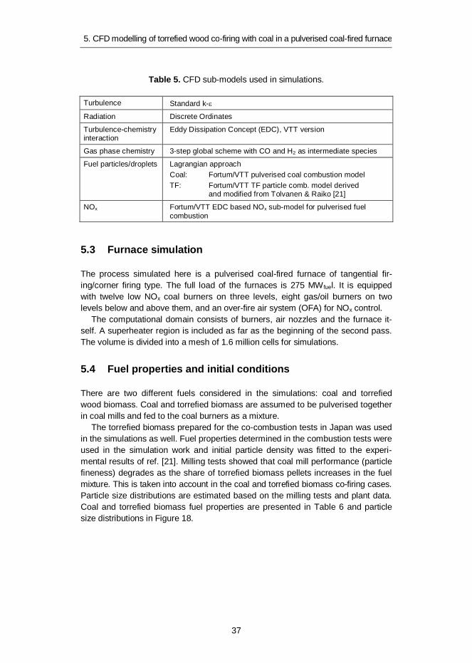
Table 5. CFD sub-models used in simulations.
Turbulence Standard k-
Radiation Discrete Ordinates
Turbulence-chemistryinteraction
Eddy Dissipation Concept (EDC), VTT version
Gas phase chemistry 3-step global scheme with CO and H2 as intermediate species
Fuel particles/droplets Lagrangian approachCoal: Fortum/VTT pulverised coal combustion modelTF: Fortum/VTT TF particle comb. model derived
and modified from Tolvanen & Raiko [21]
NOx Fortum/VTT EDC based NOx sub-model for pulverised fuelcombustion
5.3 Furnace simulation
The process simulated here is a pulverised coal-fired furnace of tangential fir-ing/corner firing type. The full load of the furnaces is 275 MW fuel. It is equippedwith twelve low NOx coal burners on three levels, eight gas/oil burners on twolevels below and above them, and an over-fire air system (OFA) for NOx control.
The computational domain consists of burners, air nozzles and the furnace it-self. A superheater region is included as far as the beginning of the second pass.The volume is divided into a mesh of 1.6 million cells for simulations.
5.4 Fuel properties and initial conditions
There are two different fuels considered in the simulations: coal and torrefiedwood biomass. Coal and torrefied biomass are assumed to be pulverised togetherin coal mills and fed to the coal burners as a mixture.
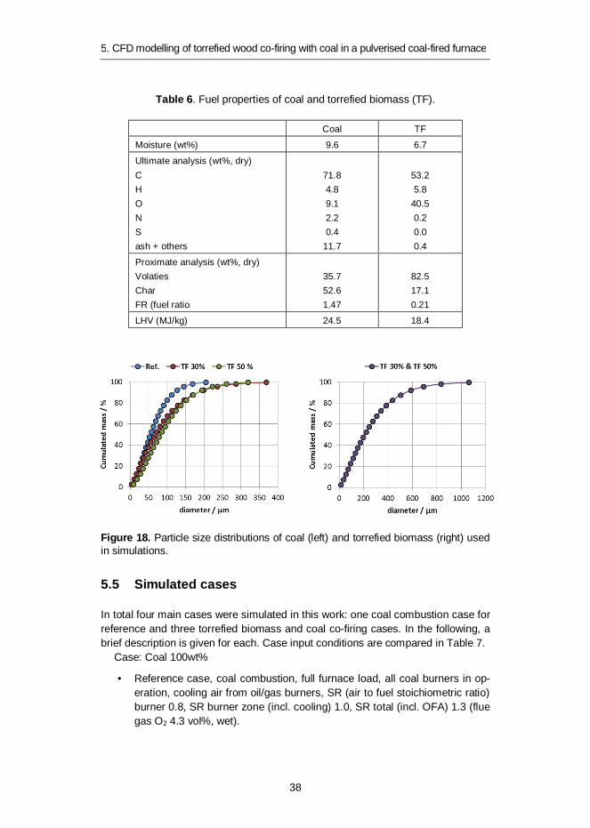
The torrefied biomass prepared for the co-combustion tests in Japan was usedin the simulations as well. Fuel properties determined in the combustion tests wereused in the simulation work and initial particle density was fitted to the experi-mental results of ref. [21]. Milling tests showed that coal mill performance (particlefineness) degrades as the share of torrefied biomass pellets increases in the fuelmixture. This is taken into account in the coal and torrefied biomass co-firing cases.Particle size distributions are estimated based on the milling tests and plant data.Coal and torrefied biomass fuel properties are presented in Table 6 and particlesize distributions in Figure 18.
5. CFD modelling of torrefied wood co-firing with coal in a pulverised coal-fired furnace
38
Table 6. Fuel properties of coal and torrefied biomass (TF).
Coal TF
Moisture (wt%) 9.6 6.7
Ultimate analysis (wt%, dry)CHONSash + others
71.84.89.12.20.4
11.7
53.25.8
40.50.20.00.4
Proximate analysis (wt%, dry)VolatiesCharFR (fuel ratio
35.752.61.47
82.517.10.21
LHV (MJ/kg) 24.5 18.4
Figure 18. Particle size distributions of coal (left) and torrefied biomass (right) usedin simulations.
5.5 Simulated cases
In total four main cases were simulated in this work: one coal combustion case forreference and three torrefied biomass and coal co-firing cases. In the following, abrief description is given for each. Case input conditions are compared in Table 7.
Case: Coal 100wt%
• Reference case, coal combustion, full furnace load, all coal burners in op-eration, cooling air from oil/gas burners, SR (air to fuel stoichiometric ratio)burner 0.8, SR burner zone (incl. cooling) 1.0, SR total (incl. OFA) 1.3 (fluegas O2 4.3 vol%, wet).
5. CFD modelling of torrefied wood co-firing with coal in a pulverised coal-fired furnace
39
Case: TF 30 wt%
• TF & coal co-firing case, share of torrefied biomass 30% by weight (24% byenergy), full furnace load, degraded coal particle fineness (see Figure 18),all coal burners in operation, cooling air from oil/gas burners, SR burner0.8, SR burner zone (incl. cooling) 1.0, SR total (incl. OFA) 1.3 (flue gas O2
4.4 vol%, wet).
Case: TF 50 wt%
• TF & coal co-firing case, share of torrefied biomass 50% by weight (43% byenergy), full furnace load, degraded coal particle fineness (see Figure 18),all coal burners in operation, cooling air from oil/gas burners, SR burner0.8, SR burner zone (incl. cooling) 1.0, SR total (incl. OFA) 1.3 (flue gas O2
4.4 vol%, wet).
Case: TF 50 wt%, fine coal
• Same as previous TF 50% case, but coal is assumed to preserve its origi-nal fineness in milling (e.g. separate milling of torrefied biomass pellets).No change in TF particle size.
Table 7. CFD case comparison.
Coal100%
TF 30%(mass basis)
TF 50%(mass basis)
Fuel input (MW)coal (%), energy basisTF (%), energy bases
275100
0
2757624
2755743
Fuel flow rate (kg/s) 11.2 12.1 12.8
Total Stoichiometric RatioSR coal burnerSR burner zone
1.30.81.0
1.30.81.0
1.30.81.0
Flue gas O2 (vol-%, wet) 4.4 4.4 4.4
Air flow rate (kg/s) 123.5 121.2 119.3
Flue gas flow rate (kg/s) 133.3 132.2 131.3
5.6 Simulation results
5.6.1 Combustion in general, temperature, heat transfer
The main observation from the simulation results is that combustion does notchange that much on a furnace scale compared to pure coal. As the torrefiedbiomass share increases, the flame stability seems to fade slowly as a conse-

5. CFD modelling of torrefied wood co-firing with coal in a pulverised coal-fired furnace
40
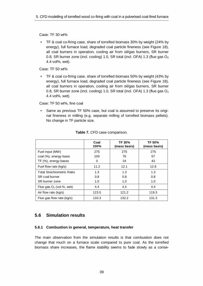
quence of larger average particle size decelerating ignition. The hottest spots movea little further away from the burner opening. According to the results, however,flames are still stable with the torrefied biomass shares of up to 50% at full burnerload. At the same time, evaporator heat transfer is weakened marginally and thefurnace exit gas temperature at nose level tends to rise by some 0–20 degrees.Assuming an original coal fineness in torrefied biomass of 50 wt%, case flamestability is excellent. Heat transfer is even enhanced compared to pure coal firing.
Temperature contours and wall incident radiation are compared for two cases,and evaporator heat transfer and furnace exit gas temperature (FEGT) for eachcase in Figures 19–21.
Figure 19. Temperature contours from one diagonal section of the furnace.
5. CFD modelling of torrefied wood co-firing with coal in a pulverised coal-fired furnace
41
Figure 20. Wall (left, front, right, rear) incident radiation.
Figure 21. Predicted evaporator heat transfer (left) and predicted Furnace Exit GasTemperature (at nose level).
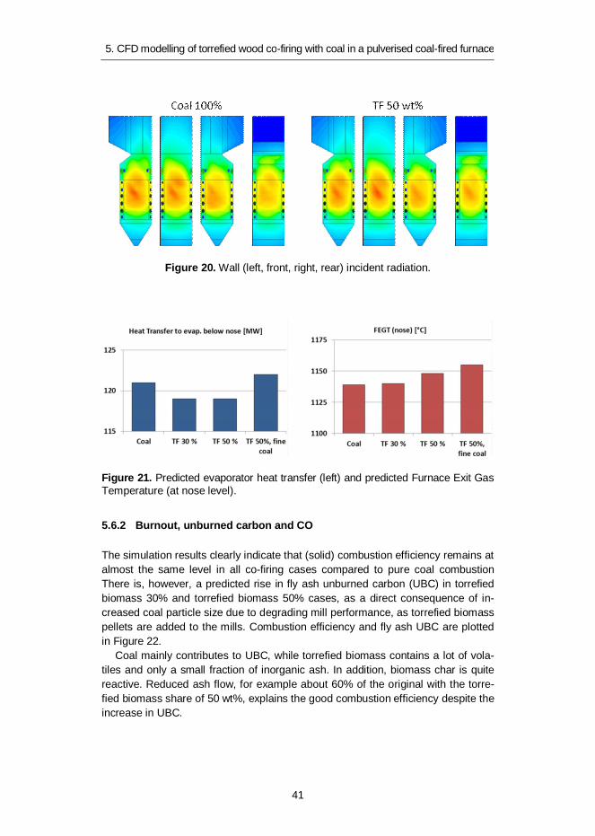
5.6.2 Burnout, unburned carbon and CO
The simulation results clearly indicate that (solid) combustion efficiency remains atalmost the same level in all co-firing cases compared to pure coal combustionThere is, however, a predicted rise in fly ash unburned carbon (UBC) in torrefiedbiomass 30% and torrefied biomass 50% cases, as a direct consequence of in-creased coal particle size due to degrading mill performance, as torrefied biomasspellets are added to the mills. Combustion efficiency and fly ash UBC are plottedin Figure 22.
Coal mainly contributes to UBC, while torrefied biomass contains a lot of vola-tiles and only a small fraction of inorganic ash. In addition, biomass char is quitereactive. Reduced ash flow, for example about 60% of the original with the torre-fied biomass share of 50 wt%, explains the good combustion efficiency despite theincrease in UBC.
5. CFD modelling of torrefied wood co-firing with coal in a pulverised coal-fired furnace
42
Figure 22. Predicted solid combustion efficiency and fly ash UBC.
The UBC level in co-firing is predicted to be very comparable to a pure coal case ifmilling performance can be maintained, as can be seen in TF 50 wt% fine coalcase assuming separate crushing of the torrefied biomass pellets.
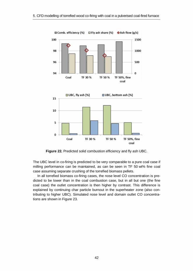
In all torrefied biomass co-firing cases, the nose level CO concentration is pre-dicted to be lower than in the coal combustion case, but in all but one (the finecoal case) the outlet concentration is then higher by contrast. This difference isexplained by continuing char particle burnout in the superheater zone (also con-tributing to higher UBC). Simulated nose level and domain outlet CO concentra-tions are shown in Figure 23.
5. CFD modelling of torrefied wood co-firing with coal in a pulverised coal-fired furnace
43
Figure 23. Predicted CO concentrations (at nose level and at domain outlet).
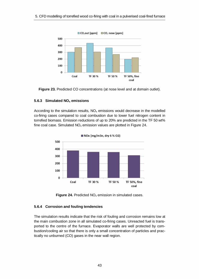
5.6.3 Simulated NOx emissions
According to the simulation results, NOx emissions would decrease in the modelledco-firing cases compared to coal combustion due to lower fuel nitrogen content intorrefied biomass. Emission reductions of up to 20% are predicted in the TF 50 wt%fine coal case. Simulated NOx emission values are plotted in Figure 24.
Figure 24. Predicted NOx emission in simulated cases.
5.6.4 Corrosion and fouling tendencies
The simulation results indicate that the risk of fouling and corrosion remains low atthe main combustion zone in all simulated co-firing cases. Unreacted fuel is trans-ported to the centre of the furnace. Evaporator walls are well protected by com-bustion/cooling air so that there is only a small concentration of particles and prac-tically no unburned (CO) gases in the near wall region.
5. CFD modelling of torrefied wood co-firing with coal in a pulverised coal-fired furnace
44
Instead, some problems might arise in the superheater region with biomassoriginated ash and inorganic gaseous species involved, especially as the gastemperature is predicted to rise in the upper part of the furnace during co-firing.
5.7 Conclusions
Based on the CFD simulations, the following conclusions can be drawn.From the combustion point of view, it seems feasible to replace coal by torre-
fied wood biomass in the unit investigated, with shares of up to 50% by weight.Flame stability could be an issue with even higher shares of torrefied biomass orpartial burner load operation with notable torrefied biomass content in fuel.
There should be no drastic change in furnace heat transfer, although a smallreduction in evaporator heat transfer rate (< 5%) might be expected. It is anticipat-ed that the furnace exit gas temperature before the superheater region will riseslightly during co-firing.
According to the model, torrefied biomass co-firing is characterised by:
combustion efficiency comparable to pure coal firing
reduced total ash flow
increased unburned carbon in fly ash, presuming that coal mill perfor-mance degrades along with the addition of torrefied biomass.
Combustion efficiency and unburned carbon can be positively affected by improv-ing mill performance if possible, or by applying separate crushing for torrefiedbiomass, for example.
The actual CO emission trend remains unclear due to modelling uncertainties,but no drastic increase is predicted. NOx emissions are reduced when increasingthe share of biomass-based fuel. A reduction of up to 20% might be possible intorrefied biomass co-firing.
Evaporator wall fouling/corrosion problems are not expected to increase in thefurnace investigated. The superheater region might be more vulnerable in thatsense with the simulated rise in furnace exit gas temperature.
6. Storage and handling properties of torrefied wood pellets
45
6. Storage and handling properties oftorrefied wood pellets
Conventional wood pellets can be considered a commodity fuel, having been on themarket since the 1980s. Their utilisation ranges from small-scale domestic heating tolarge-scale co-firing in PC boilers to replace fossil fuels. Logistics, storage and han-dling of the wood pellets have achieved a fairly well defined and controlled practice.Common expectations on torrefied wood pellets regarding storage and handlingproperties have been high. Expected enhanced durability and hydrophobicity haveeven suggested open air storage similar to coal. Little information is, however, availa-ble on the physical properties of torrefied wood pellets, although these issues have asignificant influence on the economics, safety and health issues of the industrial utili-sation of these fuels. Some basic small-scale experimental work was conducted inthe national research programme to compare torrefied wood pellet properties withconventional wood and straw pellets. These experimental methods have been de-scribed elsewhere [33] but are reproduced here for clarity.
6.1 Test procedures and materials
Physical properties of the torrefied pellets and reference pellets were determinedwith regard to mechanical durability, compression strength and bulk density. Mois-ture content and heating values were also analysed. Climate tests included equi-librium moisture content (EMC) determination, immersion tests and rain exposuretests in laboratory conditions. Standard test procedures were used when available.When possible, some durability tests were carried out in connection with EMC andrain exposure tests.
The mechanical durability of a densified fuel gives an indication of the fuel’sability to retain its form during transport and handling processes without going topieces. Durability was measured according to the existing standard (EN 15210-1)which is applicable for fuel pellets. The durability value gives the mass proportionof the sample, which remains intact after the removal of fine broken pieces (fineswhich pass through a 3.15 mm sieve). For conventional wood pellets, the mini-mum normative durability classification is equal to or greater than 97.5% [22].
Although not existing as a standard, pellet hardness is a commonly usedmeasurement to describe a pellet’s resistance to a static force applied at right

6. Storage and handling properties of torrefied wood pellets
46
angles to the radial axis of the pellet. A pellet compression strength tester (manu-factured by Amandus Kahl GmbH & Co. KG, Germany) was used for this meas-urement. The test was repeated ten times for each sample type (i.e. ten pellets ofeach sample) and the average value in kilogram equivalency is reported. Being astatic force measurement, the results are given in kg. The test equipment used isshown in Figure 25.
Figure 25. Mechanical durability (left) and compression strength (right) test equipment.
The static conditions necessary for determining equilibrium moisture content wereprovided through the use of a custom-built condensing dryer used as a climatictesting chamber, Figure 26. The device allows for the measurement and regulationof temperature, humidity, air flow and pressure. The conditions chosen for the EMCmeasurement were a temperature of 22 °C and relative air humidity (RH) of 85%.
Figure 26. The condensing dryer at VTT used as a climatic testing chamber for thedetermination of equilibrium moisture content (EMC).

6. Storage and handling properties of torrefied wood pellets
47
The climatic chamber was turned on and allowed to stabilise under the test condi-tions. A sample of each pellet type (exceeding 300 grams) was placed in an opentray made of aluminium foil. The measurements continued until the mass of all thesamples remained constant – this occurred within an approximate twenty-fourhour period. Even after three days in the chamber, no further change was meas-ured in the moisture content of the samples.
To assess the outdoor storage properties of the torrefied wood pellets, rain ex-posure and water immersion tests were conducted on pellet samples. The rainexposure text was performed as follows: a 1 kg sample of pellets was placed on a450 mm diameter Retsch 3.15 mm sieve. The amount was sufficient to cover theentire bottom of the sieve with one layer of pellets. The sieve was placed over acontainer. Simulated rainfall was realised through the use of a spray bottle fittedwith fine nozzles. In total, 400 g of water was sprayed over each sample during aone-hour period. Runoff water from the pellets drained through the sieve and wascollected in the container beneath. The mass of water not absorbed by the pelletscould then be determined. The total amount of water corresponds to rainfall of2.5 mm per hour – a level of rainfall which statistically occurs in Finland onceevery decade. This level of rain was predefined beforehand by experimentation.
The pellets were also subjected to a water immersion test. A 500 g sample ofeach pellet type was placed in a filtration bag which was then submerged for aperiod of 15 minutes in a five-litre container of water. By weighing the quantity ofwater after the immersion period, the amount of water absorbed by the pelletsample could be identified. The immersion time was fixed by pretesting.
Moisture content was determined according to the standard EN 14774-1 andbulk density according to EN 15103 [23, 24].
The torrefied biomass pellets and reference pellets used in the durability andstorage tests are listed in Table 8. The torrefied wood and forest residue pelletsare those produced by ECN in the pilot tests. Another torrefied pellet grade pro-duced by the CENER from beech wood was used as one of the reference fuels.
Table 8. Pellet samples used in the durability and storage tests.
Sampleidentification
Feedstockmaterial
Torrefactiontemperature
Details
TOP WC 235C Whole tree wood chips 235 °C ECN, PATRIG
TOP WC 245C Whole tree wood chips 245 °C ECN, PATRIG
TOP WC 255C Whole tree wood chips 255 °C ECN, PATRIG
TOP FR 240C Forest residue chips 240 °C ECN, PATRIG
TOP FR 250C B3 Forest residue chips 250 °C ECN, PATRIG, 3% binder
TOP (BEECH) CENER Beech wood 270 °C CENER, pilot
WOODPELL. Pine wood - Vapo Oy, Finland
BARKPELL. Pine bark - Sweden
STRAWPELL. Wheat straw - Denmark

6. Storage and handling properties of torrefied wood pellets
48
6.2 Results and discussion
6.2.1 Bulk and energy density, durability
Table 9 summarises the main thermodynamical and mechanical properties of thetorrefied pellets and the chosen reference fuels. Two of the pellet grades, the goodquality torrefied pellets produced by CENER from beech wood and the bark pel-lets, exhibit bulk density of over 700 kg/m3 and good durability. The mechanicaldurability of the torrefied pellets was on average lower than those of the referencefuels and below the limit value 97.5% of the EN standard (EN 14961-2:2012).
Table 9. Bulk and energy densities, mechanical durability.
Sample IDMoisturecontent(wt%)
LHVar(MJ/kg)
Bulkdensity(kg/m3)
Bulkenergydensity(GJ/m3)
Durability(%)
Compressionstrength
(kg)
TOP WC 235C 1.4 19.20 556.6 10.69 80 18.5
TOP WC 245C 2.1 20.02 633.1 12.67 92 20.8
TOP WC 255C 1.6 20.27 633.8 12.85 88 20.8
TOP FR 240C 2.8 19.67 681.3 13.40 89 17.5
TOP FR 250CB3 1.0 20.19 643.2 12.99 87 9.5
TOP (BEECH)CENER 3.6 19.55 702.3 13.73 97 21.0
WOODPELL. 6.9 17.68 678.5 12.00 98 20.5
BARKPELL. 9.0 17.78 708.8 12.60 97 20.0
STRAWPELL. 7.5 14.99 559.0 8.38 98 19.0
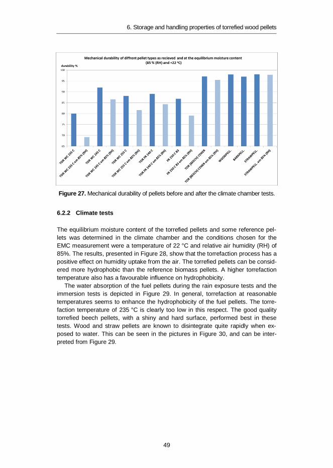
Durability tests were also performed for the torrefied pellets after the equilibriummoisture content test in the climate chamber. The results are shown in Figure 27.Mechanical durability decreased by units of approximately 10% compared to theinitial values. The compression strength test did not display any deterioration dueto the increased moisture content of the pellets. The tenacity of the pellets mayhave increased with the moisture content.
6. Storage and handling properties of torrefied wood pellets
49
Figure 27. Mechanical durability of pellets before and after the climate chamber tests.
6.2.2 Climate tests
The equilibrium moisture content of the torrefied pellets and some reference pel-lets was determined in the climate chamber and the conditions chosen for theEMC measurement were a temperature of 22 °C and relative air humidity (RH) of85%. The results, presented in Figure 28, show that the torrefaction process has apositive effect on humidity uptake from the air. The torrefied pellets can be consid-ered more hydrophobic than the reference biomass pellets. A higher torrefactiontemperature also has a favourable influence on hydrophobicity.
The water absorption of the fuel pellets during the rain exposure tests and theimmersion tests is depicted in Figure 29. In general, torrefaction at reasonabletemperatures seems to enhance the hydrophobicity of the fuel pellets. The torre-faction temperature of 235 °C is clearly too low in this respect. The good qualitytorrefied beech pellets, with a shiny and hard surface, performed best in thesetests. Wood and straw pellets are known to disintegrate quite rapidly when ex-posed to water. This can be seen in the pictures in Figure 30, and can be inter-preted from Figure 29.

6. Storage and handling properties of torrefied wood pellets
50
Figure 28. Equilibrium moisture content of torrefied and reference pellets.
Figure 29. Rain exposure and immersion tests of torrefied and reference pellets.

6. Storage and handling properties of torrefied wood pellets
51
Figure 30. Wood pellets and torrefied wood pellets before and after the rain expo-sure tests.
6.3 Conclusions
The increase in heating value and mechanical properties like bulk density anddurability is, according to the results obtained in this research work, somewhatmore modest than expected based on the public information available. Torrefac-tion temperatures of between 250 and 270 oC increases the lower heating value(LHVdb) of wood pellets compared to those produced from torrefied wood fromabout 19 MJ/kg to 21 MJ/kg. A slight increase in bulk density from a level of 650–675 kg/m3 to 630–700 kg/m3 may also be accomplished. The increase in energydensity of wood pellets from 11–12 GJ/m3 to 13–14 GJ/m3 for torrefied wood pel-lets is mainly accounted for by a lower moisture content of the torrefied pellets.
The mechanical durability of the torrefied pellets was not at the level requiredby the EN standard, except for that produced at a higher torrefaction temperaturefrom beech wood. The durability decreases by about 10% when the torrefied pel-lets are exposed to humid conditions and when they reach their equilibrium mois-ture content. The torrefaction temperature and the properties of the feedstock bothinfluence the pelletability of the torrefied material, but the exact cause and effect is
6. Storage and handling properties of torrefied wood pellets
52
unclear. Experience and the correct pellet dye configuration are, however, re-quired to obtain optimum pellet quality.
The equilibrium moisture content and the rain exposure tests showed that thetorrefied pellets are clearly more hydrophobic than wood and straw pellets and donot disintegrate completely on exposure to water. The immersion tests and therain exposure tests indicated that water absorption is lower for pellets produced inhigher torrefaction temperatures which have a denser structure (high bulk density).
Large-scale storage tests are required to have a clear view of the torrefied bio-mass pellets to withstand outdoor storage in piles, as is the case in coal storage.The partial hydrophobicity of the torrefied pellets and their ability to resist disinte-gration when wet may result in a reasonably good water tolerating upper layer onstock piles, which protects the bulk of the material from being damaged.
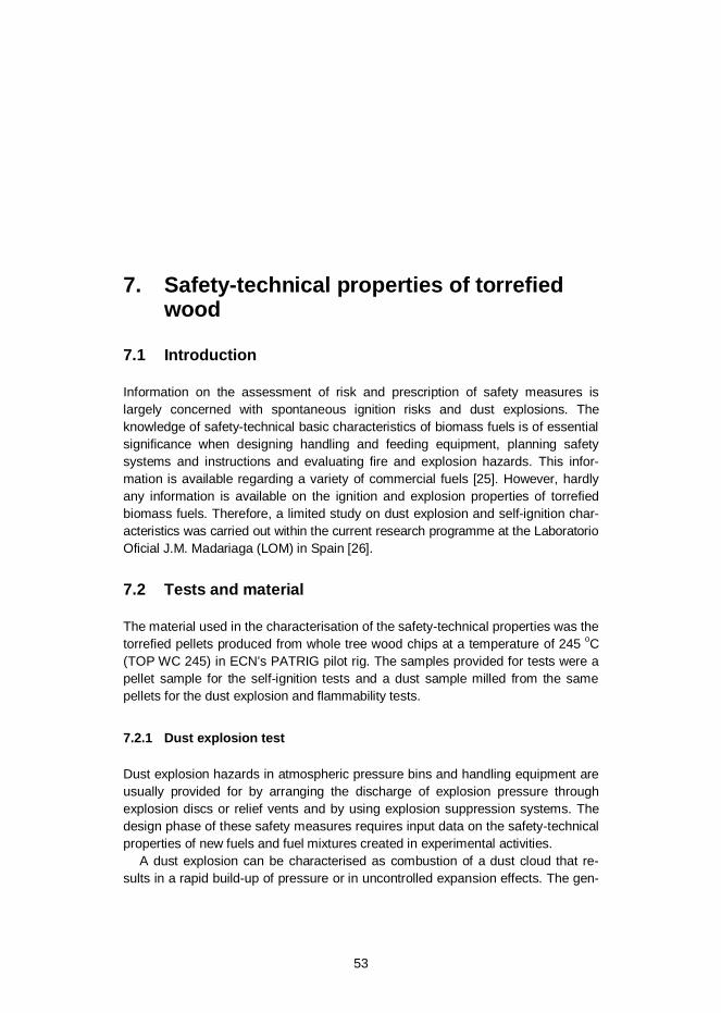
7. Safety-technical properties of torrefied wood
53
7. Safety-technical properties of torrefiedwood
7.1 Introduction
Information on the assessment of risk and prescription of safety measures islargely concerned with spontaneous ignition risks and dust explosions. Theknowledge of safety-technical basic characteristics of biomass fuels is of essentialsignificance when designing handling and feeding equipment, planning safetysystems and instructions and evaluating fire and explosion hazards. This infor-mation is available regarding a variety of commercial fuels [25]. However, hardlyany information is available on the ignition and explosion properties of torrefiedbiomass fuels. Therefore, a limited study on dust explosion and self-ignition char-acteristics was carried out within the current research programme at the LaboratorioOficial J.M. Madariaga (LOM) in Spain [26].
7.2 Tests and material
The material used in the characterisation of the safety-technical properties was thetorrefied pellets produced from whole tree wood chips at a temperature of 245 oC(TOP WC 245) in ECN’s PATRIG pilot rig. The samples provided for tests were apellet sample for the self-ignition tests and a dust sample milled from the samepellets for the dust explosion and flammability tests.
7.2.1 Dust explosion test
Dust explosion hazards in atmospheric pressure bins and handling equipment areusually provided for by arranging the discharge of explosion pressure throughexplosion discs or relief vents and by using explosion suppression systems. Thedesign phase of these safety measures requires input data on the safety-technicalproperties of new fuels and fuel mixtures created in experimental activities.
A dust explosion can be characterised as combustion of a dust cloud that re-sults in a rapid build-up of pressure or in uncontrolled expansion effects. The gen-

7. Safety-technical properties of torrefied wood
54
eration of a dust explosion requires the simultaneous occurrence of three particu-lar conditions: combustible dust, dispersive air (oxygen) and an ignition source.The explosion severity is usually expressed in terms of:
maximum explosion over pressure Pmax maximum rate of pressure rise (dP/dt)max or Kmax.
These indices are the main ones influencing the assessment and design of differentkinds of explosion relief venting and suppression. Limiting oxygen content (LOC) ininertial cases indicates at which ambient oxygen content an explosion is prevented.The lower explosion limit (LEL) describes the minimum concentration of the dust ina dust cloud which may generate an explosion. These explosion characteristicsare determined in a 20-litre sphere, Figure 31. The tests performed as part of thisproject at LOM in Spain are listed in Table 10.
Figure 31. 20-litre sphere used for dust explosion measurements.
Table 10. Explosibility tests.
Parameter Abbrev. Applied standard Test device UncertaintyMaximum explosionover pressure
Pmax EN 14034-1 20-litre sphere ± 10%
Maximum rate ofpressure rise
Kmax EN 14034-2 20-litre sphere ± 10%
Limiting OxygenConcentration
LOC EN 14034-4 20-litre sphere ± 1%
Lower Explosion Limit LEL EN 14034-3 20-litre sphere 0.1 g/m3
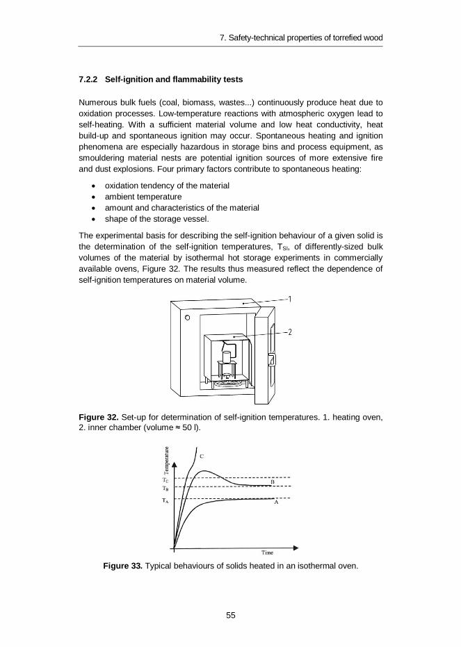
7. Safety-technical properties of torrefied wood
55
7.2.2 Self-ignition and flammability tests
Numerous bulk fuels (coal, biomass, wastes...) continuously produce heat due tooxidation processes. Low-temperature reactions with atmospheric oxygen lead toself-heating. With a sufficient material volume and low heat conductivity, heatbuild-up and spontaneous ignition may occur. Spontaneous heating and ignitionphenomena are especially hazardous in storage bins and process equipment, assmouldering material nests are potential ignition sources of more extensive fireand dust explosions. Four primary factors contribute to spontaneous heating:
oxidation tendency of the material ambient temperature amount and characteristics of the material shape of the storage vessel.
The experimental basis for describing the self-ignition behaviour of a given solid isthe determination of the self-ignition temperatures, TSI, of differently-sized bulkvolumes of the material by isothermal hot storage experiments in commerciallyavailable ovens, Figure 32. The results thus measured reflect the dependence ofself-ignition temperatures on material volume.
Figure 32. Set-up for determination of self-ignition temperatures. 1. heating oven,2. inner chamber (volume 50 l).
Figure 33. Typical behaviours of solids heated in an isothermal oven.

7. Safety-technical properties of torrefied wood
56
The sample is introduced to an oven at a set temperature and the evolution of thetemperature of the sample is observed over time. There are three types of behav-iour in the tests, Figure 33. The supercritical behaviour exhibited by curve Cshows that the production of heat reaches a point that exceeds the heat losses,resulting in non-stationary conditions, so that the temperature of the sample in-creases rapidly above Tc. This case corresponds to spontaneous combustion,since the material reacts strongly and the temperature in the basket rises rapidly,leaving the test product ashes after combustion. The self-ignition temperature isdefined as the highest temperature at which a given volume of dust will not ignite.
The ignition temperature of the product is determined for different sample vol-umes, typically between 50 cm3 and 1500 cm3. Once the self-temperature fordifferent sample volumes is obtained, log (V/A) versus temperature (1/TSI in K-1)can be represented in an Arrhenius-type diagram. The regression curve of all testresults shows the transition between the stationary and non-stationary behaviourof the samples.
In every test, the auto-ignition temperature and the time taken from reachingthe temperature of the oven until ignition occurs (induction time) are recorded.With the help of the above-mentioned diagrams, the size of storage that will leadto spontaneous combustion and also the time needed to produce ignition can beestimated.
The flammability and spontaneous ignition tests performed at LOM are listed inTable 11.
Table 11. Flammability and spontaneous ignition tests.
Parameter Abbrev. Applied standard Test device UncertaintyMinimum IgnitionTemperature on a layer
MIT-l EN 50281-2-1:1999 Flat oven(plate)
5 K
Minimum IgnitionTemperature in a cloud
MIT-c EN 50281-2-1:1999 Vertical oven 5 K
Minimum IgnitionEnergy
MIE EN 13821:2003 MIKE3 1 mJ
Self-ignitionTemperature
TSI EN 15188:2008 Isothermaloven
5 K
7.3 Results
7.3.1 Explosion severity
The dust explosion tests in the 20-litre sphere were conducted over a dust con-centration range (explosive range) of 125–2250 g/m3. The optimum dust concen-tration was found to be 1250 g/m3. The Limiting Oxygen Concentration of a dustcloud (LOC) is defined as the maximum oxygen concentration in a mixture ofcombustible dust and air and an inert gas, in which an explosion will not occur.
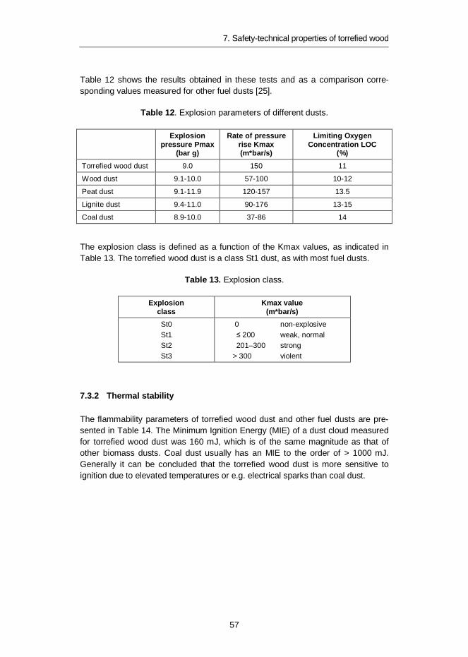
7. Safety-technical properties of torrefied wood
57
Table 12 shows the results obtained in these tests and as a comparison corre-sponding values measured for other fuel dusts [25].
Table 12. Explosion parameters of different dusts.
Explosionpressure Pmax
(bar g)
Rate of pressurerise Kmax(m*bar/s)
Limiting OxygenConcentration LOC
(%)Torrefied wood dust 9.0 150 11
Wood dust 9.1-10.0 57-100 10-12
Peat dust 9.1-11.9 120-157 13.5
Lignite dust 9.4-11.0 90-176 13-15
Coal dust 8.9-10.0 37-86 14
The explosion class is defined as a function of the Kmax values, as indicated inTable 13. The torrefied wood dust is a class St1 dust, as with most fuel dusts.
Table 13. Explosion class.
Explosionclass
Kmax value(m*bar/s)
St0St1St2St3
0 non-explosive 200 weak, normal
201–300 strong> 300 violent
7.3.2 Thermal stability
The flammability parameters of torrefied wood dust and other fuel dusts are pre-sented in Table 14. The Minimum Ignition Energy (MIE) of a dust cloud measuredfor torrefied wood dust was 160 mJ, which is of the same magnitude as that ofother biomass dusts. Coal dust usually has an MIE to the order of > 1000 mJ.Generally it can be concluded that the torrefied wood dust is more sensitive toignition due to elevated temperatures or e.g. electrical sparks than coal dust.
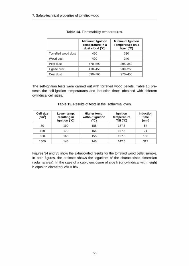
7. Safety-technical properties of torrefied wood
58
Table 14. Flammability temperatures.
Minimum IgnitionTemperature in adust cloud (oC)
Minimum IgnitionTemperature on a
layer (oC)Torrefied wood dust 460 330
Wood dust 420 340
Peat dust 470–590 305–340
Lignite dust 410–450 230–250
Coal dust 590–760 270–450
The self-ignition tests were carried out with torrefied wood pellets. Table 15 pre-sents the self-ignition temperatures and induction times obtained with differentcylindrical cell sizes.
Table 15. Results of tests in the isothermal oven.
Cell size(cm3)
Lower temp.resulting inignition (oC)
Higher temp.without ignition
(oC)
Ignitiontemperature
TSI (oC)
Inductiontime(min)
50 190 185 187.5 54
150 170 165 167.5 71
350 160 155 157.5 130
1500 145 140 142.5 317
Figures 34 and 35 show the extrapolated results for the torrefied wood pellet sample.In both figures, the ordinate shows the logarithm of the characteristic dimension(volume/area). In the case of a cubic enclosure of side h (or cylindrical with heighth equal to diameter) V/A = h/6.

7. Safety-technical properties of torrefied wood
59
Figure 34. Extrapolation of results: size versus temperature.
Figure 35. Extrapolation of results: size versus time.
Table 16 summarises the interdependence between the size of storage bin (cu-bic), storage temperature and induction time. Given the experimental features ofthe test method and this interpretation of results through a process of extrapola-tion, these values should be viewed with caution. Therefore, the lines outlining theregion of ignition from the region of non-ignition in Figures 34 and 35 should beregarded as uncertainty regions (bands instead of lines), so that the closer the
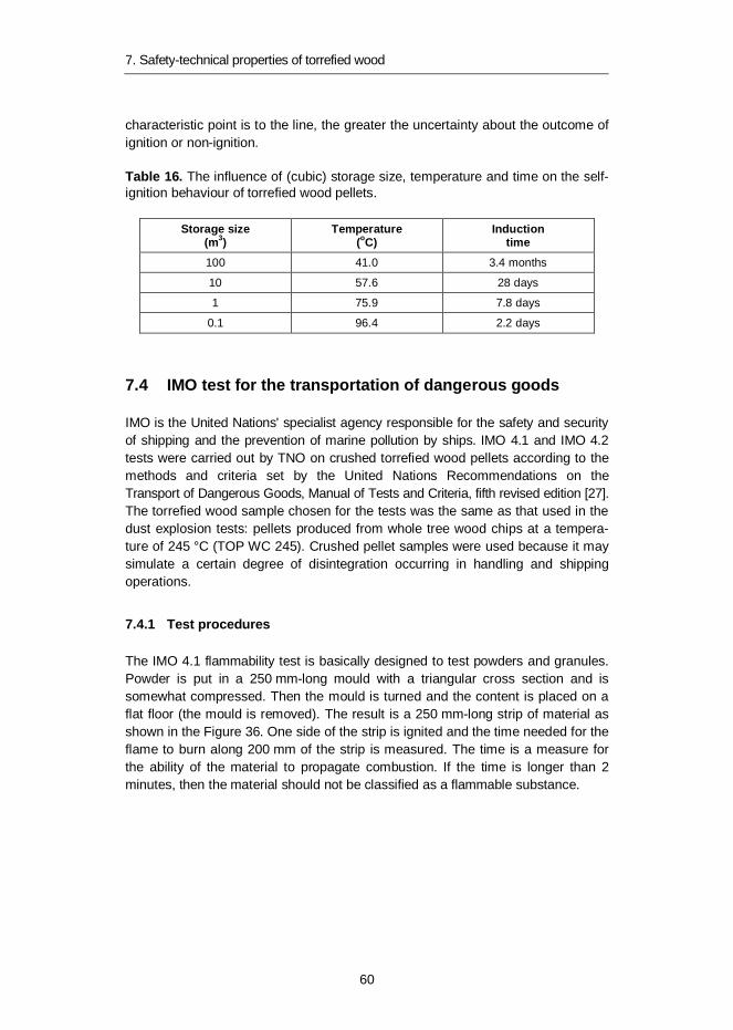
7. Safety-technical properties of torrefied wood
60
characteristic point is to the line, the greater the uncertainty about the outcome ofignition or non-ignition.
Table 16. The influence of (cubic) storage size, temperature and time on the self-ignition behaviour of torrefied wood pellets.
Storage size(m3)
Temperature(oC)
Inductiontime
100 41.0 3.4 months
10 57.6 28 days
1 75.9 7.8 days
0.1 96.4 2.2 days
7.4 IMO test for the transportation of dangerous goods
IMO is the United Nations' specialist agency responsible for the safety and securityof shipping and the prevention of marine pollution by ships. IMO 4.1 and IMO 4.2tests were carried out by TNO on crushed torrefied wood pellets according to themethods and criteria set by the United Nations Recommendations on theTransport of Dangerous Goods, Manual of Tests and Criteria, fifth revised edition [27].The torrefied wood sample chosen for the tests was the same as that used in thedust explosion tests: pellets produced from whole tree wood chips at a tempera-ture of 245 °C (TOP WC 245). Crushed pellet samples were used because it maysimulate a certain degree of disintegration occurring in handling and shippingoperations.
7.4.1 Test procedures
The IMO 4.1 flammability test is basically designed to test powders and granules.Powder is put in a 250 mm-long mould with a triangular cross section and issomewhat compressed. Then the mould is turned and the content is placed on aflat floor (the mould is removed). The result is a 250 mm-long strip of material asshown in the Figure 36. One side of the strip is ignited and the time needed for theflame to burn along 200 mm of the strip is measured. The time is a measure forthe ability of the material to propagate combustion. If the time is longer than 2minutes, then the material should not be classified as a flammable substance.
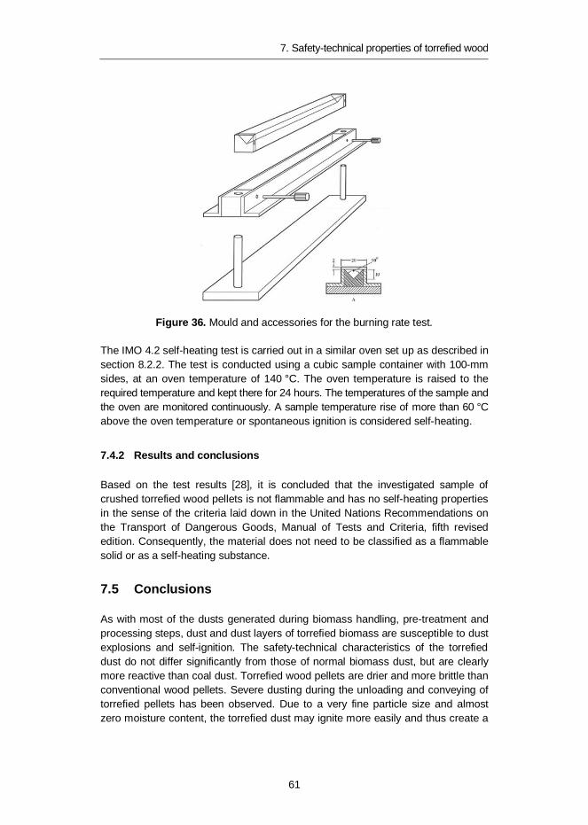
7. Safety-technical properties of torrefied wood
61
Figure 36. Mould and accessories for the burning rate test.
The IMO 4.2 self-heating test is carried out in a similar oven set up as described insection 8.2.2. The test is conducted using a cubic sample container with 100-mmsides, at an oven temperature of 140 °C. The oven temperature is raised to therequired temperature and kept there for 24 hours. The temperatures of the sample andthe oven are monitored continuously. A sample temperature rise of more than 60 °Cabove the oven temperature or spontaneous ignition is considered self-heating.
7.4.2 Results and conclusions
Based on the test results [28], it is concluded that the investigated sample ofcrushed torrefied wood pellets is not flammable and has no self-heating propertiesin the sense of the criteria laid down in the United Nations Recommendations onthe Transport of Dangerous Goods, Manual of Tests and Criteria, fifth revisededition. Consequently, the material does not need to be classified as a flammablesolid or as a self-heating substance.
7.5 Conclusions
As with most of the dusts generated during biomass handling, pre-treatment andprocessing steps, dust and dust layers of torrefied biomass are susceptible to dustexplosions and self-ignition. The safety-technical characteristics of the torrefieddust do not differ significantly from those of normal biomass dust, but are clearlymore reactive than coal dust. Torrefied wood pellets are drier and more brittle thanconventional wood pellets. Severe dusting during the unloading and conveying oftorrefied pellets has been observed. Due to a very fine particle size and almostzero moisture content, the torrefied dust may ignite more easily and thus create a

7. Safety-technical properties of torrefied wood
62
larger dust explosion risk than conventional biomass dusts and coal dust. Theelimination of dust formation and ignition sources is therefore critical in the wholeutilisation chain. The self-heating and spontaneous ignition behaviour of the torre-fied wood pellets is more difficult to predict, partly because of the long time spanthese reactions require, but these hazards cannot be neglected in the large-scalestorage of the fuel.
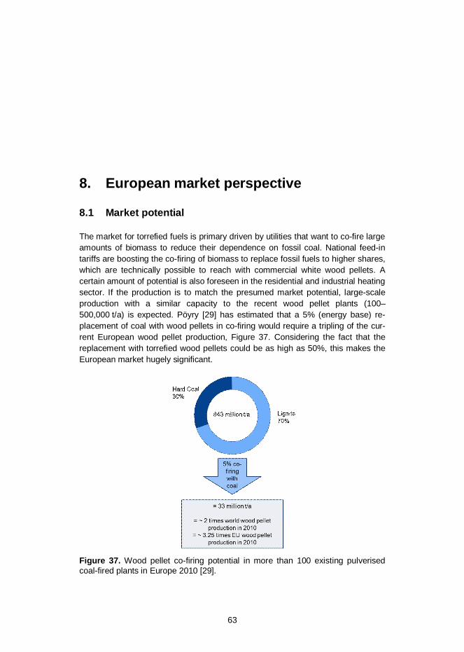
8. European market perspective
63
8. European market perspective
8.1 Market potential
The market for torrefied fuels is primary driven by utilities that want to co-fire largeamounts of biomass to reduce their dependence on fossil coal. National feed-intariffs are boosting the co-firing of biomass to replace fossil fuels to higher shares,which are technically possible to reach with commercial white wood pellets. Acertain amount of potential is also foreseen in the residential and industrial heatingsector. If the production is to match the presumed market potential, large-scaleproduction with a similar capacity to the recent wood pellet plants (100–500,000 t/a) is expected. Pöyry [29] has estimated that a 5% (energy base) re-placement of coal with wood pellets in co-firing would require a tripling of the cur-rent European wood pellet production, Figure 37. Considering the fact that thereplacement with torrefied wood pellets could be as high as 50%, this makes theEuropean market hugely significant.
Figure 37. Wood pellet co-firing potential in more than 100 existing pulverisedcoal-fired plants in Europe 2010 [29].

8. European market perspective
64
According to Pöyry, Western Europe will be the largest wood pellet consumer inthe future. The consumption is estimated to grow from about 12 million tonnes in2010 to 25 million tonnes in 2020 [29]. Although the largest pellet production ca-pacities are forecasted to remain in Europe, a region with strong competition forraw material, the growing demand will increasingly be satisfied by imports fromother regions. Imports from North America dominate and the transatlantic trade ofpellets exceeded 3 million tonnes in 2012 [30]. The largest trade streams withinEurope are going from Eastern Europe and Russia to Western Europe. The globalpellet trade streams are depicted in Figure 38. There is good reason to believethat the future trade flows of torrefied biomass pellets will follow the same routesas the current wood pellets trade streams.
Concern regarding the sustainability of solid biomass and new EU directivesmay change future market perspectives. The production of second generationbiofuels for transport is also a potential consumer area that has not been dis-cussed here due to highly diverse business scenarios.
Figure 38. Global wood pellet trade flows in 2012 [30].
8.2 Woody biomass availability
European wood resources offer a raw material base for a variety of industries suchas sawn wood, wood panels, pulp and paper, and bioenergy. From the geograph-ical point of view, forests are unevenly distributed in the EU, with Germany,France, Sweden and Finland having the largest forest resources. There are alsovariations in the wood processing structure with the pulp industry playing an im-portant role in the Nordic countries, whereas in Central Europe the wood productsindustry is the largest wood processing sector.
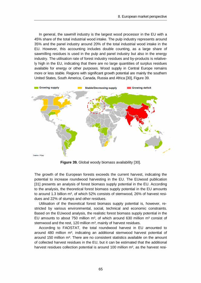
8. European market perspective
65
In general, the sawmill industry is the largest wood processor in the EU with a45% share of the total industrial wood intake. The pulp industry represents around35% and the panel industry around 20% of the total industrial wood intake in theEU. However, this accounting includes double counting, as a large share ofsawmilling residues is used in the pulp and panel industry but also in the energyindustry. The utilisation rate of forest industry residues and by-products is relative-ly high in the EU, indicating that there are no large quantities of surplus residuesavailable for energy or other purposes. Wood supply in Central Europe remainsmore or less stable. Regions with significant growth potential are mainly the southernUnited States, South America, Canada, Russia and Africa [30], Figure 39.
Figure 39. Global woody biomass availability [30].
The growth of the European forests exceeds the current harvest, indicating thepotential to increase roundwood harvesting in the EU. The EUwood publication[31] presents an analysis of forest biomass supply potential in the EU. Accordingto the analysis, the theoretical forest biomass supply potential in the EU amountsto around 1.3 billion m³, of which 52% consists of stemwood, 26% of harvest resi-dues and 22% of stumps and other residues.
Utilisation of the theoretical forest biomass supply potential is, however, re-stricted by various environmental, social, technical and economic constraints.Based on the EUwood analysis, the realistic forest biomass supply potential in theEU amounts to about 750 million m³, of which around 630 million m³ consist ofstemwood and the rest, 120 million m³, mainly of harvest residues.
According to FAOSTAT, the total roundwood harvest in EU amounted toaround 480 million m³, indicating an additional stemwood harvest potential ofaround 150 million m³. There are no consistent statistics available on the amountof collected harvest residues in the EU, but it can be estimated that the additionalharvest residues collection potential is around 100 million m³, as the harvest resi-
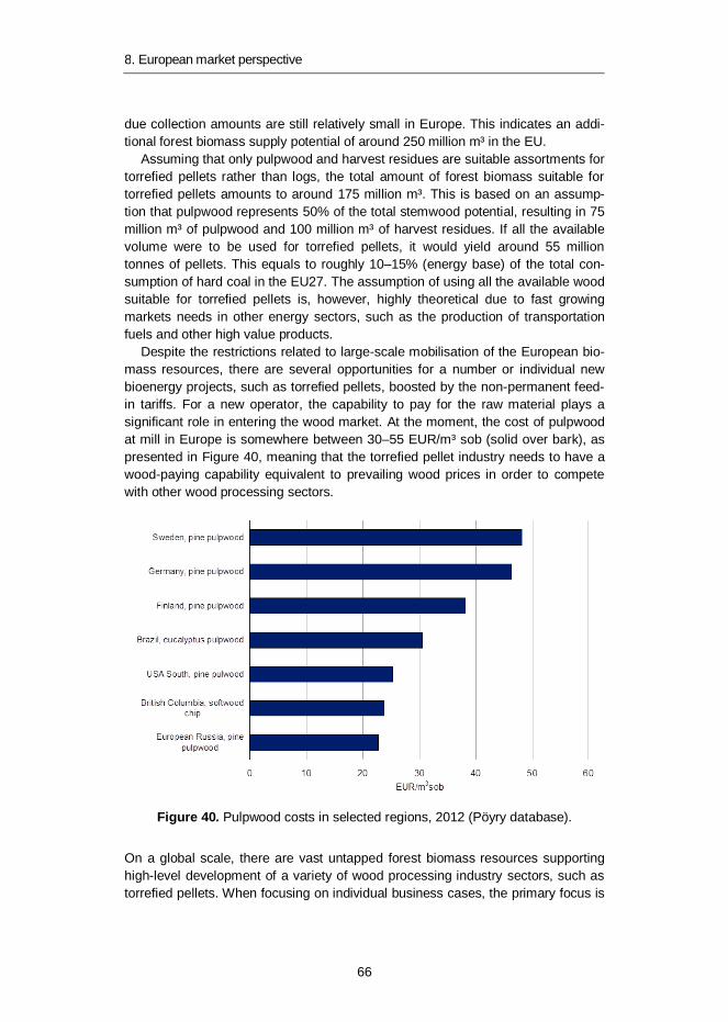
8. European market perspective
66
due collection amounts are still relatively small in Europe. This indicates an addi-tional forest biomass supply potential of around 250 million m³ in the EU.
Assuming that only pulpwood and harvest residues are suitable assortments fortorrefied pellets rather than logs, the total amount of forest biomass suitable fortorrefied pellets amounts to around 175 million m³. This is based on an assump-tion that pulpwood represents 50% of the total stemwood potential, resulting in 75million m³ of pulpwood and 100 million m³ of harvest residues. If all the availablevolume were to be used for torrefied pellets, it would yield around 55 milliontonnes of pellets. This equals to roughly 10–15% (energy base) of the total con-sumption of hard coal in the EU27. The assumption of using all the available woodsuitable for torrefied pellets is, however, highly theoretical due to fast growingmarkets needs in other energy sectors, such as the production of transportationfuels and other high value products.
Despite the restrictions related to large-scale mobilisation of the European bio-mass resources, there are several opportunities for a number or individual newbioenergy projects, such as torrefied pellets, boosted by the non-permanent feed-in tariffs. For a new operator, the capability to pay for the raw material plays asignificant role in entering the wood market. At the moment, the cost of pulpwoodat mill in Europe is somewhere between 30–55 EUR/m³ sob (solid over bark), aspresented in Figure 40, meaning that the torrefied pellet industry needs to have awood-paying capability equivalent to prevailing wood prices in order to competewith other wood processing sectors.
Figure 40. Pulpwood costs in selected regions, 2012 (Pöyry database).
On a global scale, there are vast untapped forest biomass resources supportinghigh-level development of a variety of wood processing industry sectors, such astorrefied pellets. When focusing on individual business cases, the primary focus is
8. European market perspective
67
not necessarily on macro-level wood availability, but on biomass resources thatare sustainable, large enough for an individual mill and accessible at a reasonablelevel of effort and cost. In this case, smaller amounts of biomass can also be ofinterest, such as forest industry residues that have been tapped from the forestsbut have remained unutilised at the wood processing site. In general, the utilisa-tion rate of forest industry residues is relatively high, but for example in Russia andCanada there might be opportunities to find surplus volumes of forest industryresidues. In Russia there is also the potential to increase the utilisation of low-quality roundwood originating as a by-product from industrial roundwood harvesting.
In the southern United States, the decrease in forest industry production in thepast has increased the amount of unmobilised plantation wood in the region. Cur-rently the amount of unmobilised forest biomass in the south-eastern UnitedStates is somewhere around 100 million m³. Commercially focused forestry prac-tices supporting wood mobilisation makes the region an attractive basis for newbiomass-based investments. In Brazil, plantation-based forestry may offer poten-tial for bioenergy-related operations.
9. Summary and conclusions
68
9. Summary and conclusions
There is growing interest both in Finland and internationally to substitute fossil coalin power and heat production, given the potential for the significant environmentalbenefits in terms of net CO2 emission reductions and fulfilling the European andnational 2020 targets for renewable energy. One current option is to use torrefiedbiomass as a fuel, especially as pellets for co-firing in pulverised coal-fired powerplants. This publication summarises the results of experimental work on torrefac-tion carried out with Finnish wood fuels.
Five wood fuels were chosen for preliminary laboratory-scale testing at ECN inthe Netherlands. Based on the results, two typical wood fuels, wood chips andcrushed forest residue chips, were chosen for pilot-scale tests in the ECN PATRIGtorrefaction test rig. Temperature ranges from 235 to 260 oC were tested. ThePATRIG production runs confirmed that with the torrefaction temperatures men-tioned, good quality torrefied materials were produced except at 235 °C. Here thetorrefaction temperature was too low. Furthermore, it was confirmed on a semi-industrial scale that good pellets can be produced from these materials except forthe 260 °C torrefied forest residue chips. Overall, it can be concluded that wholetree chips and forest residue chips can be torrefied in quite a broad temperaturerange, but pelletising the torrefied wood fuels produced at high torrefaction tem-peratures is not a straightforward procedure and may need some adjustments andbinders to be successful.
CFD was applied to simulate the co-firing of torrefied wood biomass with coal ina pulverised coal-fired furnace. The goal of the work was to investigate the feasi-bility of torrefied fuels to replace part of the coal from the combustion and furnaceprocess point of view. From the combustion point of view it seems feasible toreplace coal with torrefied wood biomass in the unit investigated with shares of upto 50% by weight. NOx emissions are reduced when the share of biomass-basedfuel is increased. A reduction of up to 20% might be possible in torrefied biomassco-firing. Evaporator wall fouling/corrosion problems are not expected to increase.
Common expectations of torrefied wood pellets regarding storage and handlingproperties have been high, but little information relating to practical experience isavailable. Basic small-scale experiments were carried out to compare torrefiedwood pellet properties with conventional wood and straw pellets. The mechanicaldurability of the torrefied pellets were not at the level required by the EN standard,

9. Summary and conclusions
69
except for the one produced at a higher torrefaction temperature from beechwood. Durability decreases by about 10% when the torrefied pellets are exposedto humid conditions and reach their equilibrium moisture content. The equilibriummoisture content and the rain exposure tests showed that the torrefied pellets areclearly more hydrophobic than wood and straw pellets and do not disintegratecompletely on exposure to water. Water absorption is lower for pellets produced athigher torrefaction temperatures having a denser structure. Large-scale storagetests are required to provide a clear view of the ability of torrefied biomass pelletsto withstand outdoor storage in piles, as is the case in coal storage.
The knowledge of basic safety-technical characteristics of biomass fuels is ofessential significance when designing handling and feeding equipment, planningsafety systems and instructions and evaluating fire and explosion hazards. How-ever, hardly any information is available on the ignition and explosion properties oftorrefied biomass fuels. Therefore, a limited study on dust explosion and self-ignition characteristics was carried out. The safety-technical characteristics of thetorrefied dust do not differ significantly from those of normal biomass dust, but areclearly more reactive than coal dust. Torrefied wood pellets are drier and morebrittle than conventional wood pellets. Severe dusting during the unloading andconveying of torrefied pellets has been observed. Due to a very fine particle sizeand almost zero moisture content, torrefied dust may ignite more easily and thuscreate a larger dust explosion risk than conventional biomass dusts and coal dust.The elimination of dust formation and ignition sources is therefore critical in thewhole utilisation chain.
The commercial development of torrefaction is currently in its early phase. Sev-eral technology companies and their industrial partners are moving towards com-mercial market introduction. The current general view is that most of the demon-stration plants have technical problems which have delayed their commercialoperation. The market is expected to move forward but the available public informationis very limited, especially concerning the technologies used and volumes produced.
It is estimated that it would be possible to replace about half of the solid fuelwith torrefied pellets in pulverised coal-fired combined heat and power plantswithout major new investments. A prerequisite for this is that the torrefaction pro-cess is able to convert the biomass to a satisfactorily brittle solid fuel to be milledtogether with coal, in order to produce a fuel mix which fulfils the requirements ofthe PC boiler. Considering the fact that replacement with torrefied wood pelletscould be as high as 50% makes the European market hugely significant.
The utilisation rate of forest industry residues and by-products is relatively highin the EU, indicating that there are no large quantities of surplus residues availablefor energy or other purposes. Wood supply in Central Europe remains more orless stable. Despite the restrictions related to large-scale activation of the Europe-an biomass resources, there are several opportunities for a number of individualnew bioenergy projects, such as torrefied pellets. However, the capability to payfor the raw material plays a significant role in entering the wood market.
Further development of torrefaction technologies and supporting activities onthe market introduction of torrefaction-based bioenergy carriers are the focus

9. Summary and conclusions
70
areas of an ongoing (2012–2015) EU project entitled Production of Solid Sustain-able Energy Carriers from Biomass by Means of Torrefaction “SECTOR” [32]. Theproject is coordinated by the German Biomass Research Centre (DBFZ). VTT isone of the 22 participants involved in the project.
71
References
1. Kleinschmidt, C.P. Overview of international developments in torrefaction, IEABioenergy Torrefaction workshop, Graz, Austria, 28 January 2011.
2. Bergman, P.C.A., Boersma, A.R., Zwart, R.W.R., Kiel, J.H.A. Torrefaction forbiomass co-firing in existing coal-fired power stations. Energy research Centreof the Netherlands. Report ECN-C--05-013, 2005. 71 p.
3. Bergman, P.C.A. Combined torrefaction and pelletisation. Energy researchCentre of the Netherlands. Report ECN-C--05-073, 2005. 29 p.
4. Kiel, J., Zwart, R., Verhoeff, F. Torrefaction by ECN, SECTOR/IEA BioenergyTorrefaction Workshop, 20th European Biomass Conference and Exhibition,Milan, Italy, 21 June, 2012.
5. Kiel, J. ECN’s torrefaction-based BO2-technology – from pilot to demo, IEABioenergy workshop Torrefaction, Graz, Austria, 28 January 2011.
6. Van der Stelt, M.J.C., Gerhauser, H., Kiel, J.H.A., Ptasinski, K.J. Biomassupgrading by torrefaction for the production of biofuels. A review. Biomass &Bioenergy, Vol. 35(2011)3748–3762.
7. Livingston, W.R. Recent developments in biomass co-firing in large coal-firedutility boilers. IEA Clean Coal Conference, Copenhagen, Denmark, 27 March 2012.
8. Phanphanich, M., Mani, S. Impact of torrefaction on the grindability and fuelcharacteristics of forest biomass. Bioresource Technology 102(2011)1246–1253.
9. Chew, J.J., Doshi, V. Recent advances in biomass pretreatment – Torrefactionfundamentals and technology. Renewable and Sustainable Energy Reviews15(2011)4212–4222.
10. Bridgeman, T.G., Jones, J.M., Williams, A., Waldron, D.J. An investigation ofthe grindability of two torrefied energy crops. Fuel 89(2010)3911–3918.
11. Agar, D., Wihersaari, M. Bio-coal, torrefied lignocellulosic resources – Keyproperties for its use in co-firing with fossil coal – Their status. Short Commu-nication. Biomass and Bioenergy 44(2012)107–111.
12. Stelte, W., Holm, J.K., Sanadi, R.A., Søren Barsberg, S., Ahrenfeldt, J., Hen-riksen, U.B. Fuel pellets from biomass: The importance of the pelletizing
72
pressure and its dependency on the processing conditions. Fuel90(2011)3285–3290.
13. Stelte, W., Holm, J.K., Sanadi, R.A., Søren Barsberg, S., Ahrenfeldt, J., Hen-riksen, U.B. A study of bonding and failure mechanisms in fuel pellets fromdifferent biomass resources. Biomass and Bioenergy 35(2011)910–918.
14. Stelte, W., Dahl, J., Nielsen, N.P.K., Hansen, H.O. Densification concepts fortorrefied biomass, SECTOR/IEA Bioenergy Torrefaction Workshop, 20th Eu-ropean Biomass Conference and Exhibition, Milan, Italy, 21 June, 2012.
15. Post van den Burg, R. Topell on Torrefaction. International Workshop onBiomass Torrefaction for Energy, Albi, France, 10 May, 2012.
16. Mateos, D. Presentation of the 1st Industrial TORSPYD Plant. InternationalWorkshop on Biomass Torrefaction for Energy, Albi, France, 10 May, 2012.
17. Hiltunen, J. ANDRITZ Torrefaction Demo Plants, Biohiilen tuotanto ja käyttö,edellytykset ja mahdollisuudet Suomessa, Hanasaari, Espoo 29 November, 2012.
18. Stramproy Green Technology. Available: http://www.stramproygreen.nl/.
19. Verhoeff, F., Kuipers, J., Pels, J., Kiel, J. Torrefaction and pelletizing testswith Finnish wood fuels, ECN project report, April 2011. Not published.
20. Jukola, P. CFD Modelling of Torrefied Biomass or Bio-Oil Co-firing with Coalin a Pulverized Coal Fired Furnace, VTT Research Report VTT-R-00526-13,March 2013. Not published.
21. Tolvanen, H., Raiko, R. Torrefied Wood Combustion Reaction Kinetics Study,Research Report, Tampere University of Technology, 24 July, 2012.
22. EN 15210-1:2010, Solid biofuels – Determination of mechanical durability ofpellets and briquettes – Part 1: Pellets.
23. EN 14774-1:2009, Solid biofuels – Determination of moisture content – Ovendry method – Part 1: Total moisture – Reference method.
24. EN 15103:2010, Solid biofuels – Determination of bulk density.
25. Wilén, C., Moilanen, A., Rautalin, A., Torrent, J., Conde, E., Lödel, R., Car-son, D., Timmers, P., Brehm, K. Safe handling of renewable fuels and fuelmixtures. VTT Publications 394. Espoo 1999. 117 p.
73
26. Torrent, J. Test report on characterization of flammable solids, torrefied woodfuel. Laboratorio Oficial J.M. Madariaga. October 2011. Not published.
27. Recommendations on the transport of dangerous goods, Manual of tests andcriteria, fifth revised edition. United Nations, New York and Geneva, 2009.456 p.
28. Mak, W.A. Flammability and self-heating properties of a sample of crushedtorrefied wood pellets. TNO report TNO-DV 2011 C266. September 2011. Notpublished.
29. Pellets – Becoming a Global Commodity. Pöyry view point: Global market,players and trade to 2020. Pöyry Managing Consulting Oy. 263 p.
30. Röder, H. Global pellet markets and price forecasting. Pellet conference,Wels, Austria, 28 February 2013.
31. Mantau, U. et al. Real potential for changes in growth and use of EU forests,EUWood. Final report 30 June 2010. 160 p.
32. Production of Solid Sustainable Energy Carriers from Biomass by Means ofTorrefaction “SECTOR”. Available: http://www.sector-project.eu.
33. Järvinen, T., Agar D. Bio-coal storage and handling properties – measuredproperties of fuel pellets made from torrefied woody biomass. Biomass andBioenergy (manuscript submitted April 2013).

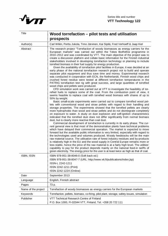
Series title and numberVTT Technology 122
Title Wood torrefaction – pilot tests and utilisationprospects
Author(s) Carl Wilén, Perttu Jukola, Timo Järvinen, Kai Sipilä, Fred Verhoeff & Jaap Kiel
Abstract The research project “Torrefaction of woody biomasses as energy carriers for theEuropean markets” was carried out within the Tekes BioRefine programme in2010–2012 and was coordinated by VTT. The main objective of the project was tocreate a discussion platform and collate basic information for the Finnish industrialstakeholders involved in developing torrefaction technology or planning to includetorrefied biomass in their fuel supply for energy production.
Given the availability of torrefaction pilot facilities in Europe, it was decided at anearly phase of the national torrefaction research project not to build and operateseparate pilot equipment and thus save time and money. Experimental researchwas conducted in cooperation with ECN, the Netherlands. Finnish wood chips andcrushed forest residue were tested at different torrefaction temperatures in thePATRIG torrefaction test rig with great success, and large quantities of torrefiedwood chips and pellets were produced.
CFD simulation work was carried out at VTT to investigate the feasibility of tor-refied fuels to replace some of the coal. From the combustion point of view, itseems feasible to replace coal with torrefied wood biomass with shares of up to50% by weight.
Basic small-scale experiments were carried out to compare torrefied wood pel-lets with conventional wood and straw pellets with regard to their handling andstorage properties. The experiments showed that the torrefied pellets are clearlymore hydrophobic than wood and straw pellets and do not disintegrate completelyon exposure to water. A study on dust explosion and self-ignition characteristicsindicated that the torrefied dust does not differ significantly from normal biomassdust, but is clearly more reactive than coal dust.
Commercial development of torrefaction is currently in its early phase. The cur-rent general view is that most of the demonstration plants have technical problemswhich have delayed their commercial operation. The market is expected to moveforward but the available public information is very limited, especially with regard tothe technologies used and volumes produced. Woody feedstocks will be the mainraw material source. The utilisation rate of forest industry residues and by-productsis relatively high in the EU and the wood supply in Central Europe remains more orless stable, hence the price of the raw material is at a fairly high level. The utilities’capability to pay for the product depends mainly on the national feed-in tariffs ofgreen electricity. The energy price for the user is at least twice as high as that of coal.
ISBN, ISSN ISBN 978-951-38-8046-0 (Soft back ed.)ISBN 978-951-38-8047-7 (URL: http://www.vtt.fi/publications/index.jsp)ISSN-L 2242-1211ISSN 2242-1211 (Print)ISSN 2242-122X (Online)
Date September 2013
Language English, Finnish abstract
Pages 73 p.
Name of the project Torrefaction of woody biomasses as energy carriers for the European markets
Keywords Torrefaction, pellets, biomass, co-firing, pilot plant, storage, safety issues, simulation
Publisher VTT Technical Research Centre of FinlandP.O. Box 1000, FI-02044 VTT, Finland, Tel. +358 20 722 111

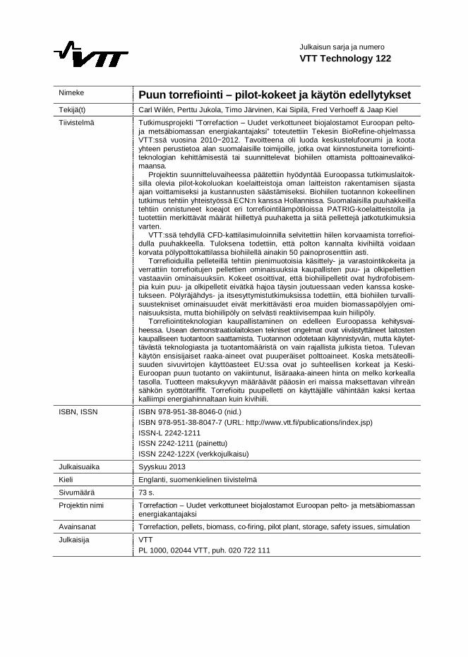
Julkaisun sarja ja numeroVTT Technology 122
Nimeke Puun torrefiointi – pilot-kokeet ja käytön edellytyksetTekijä(t) Carl Wilén, Perttu Jukola, Timo Järvinen, Kai Sipilä, Fred Verhoeff & Jaap Kiel
Tiivistelmä Tutkimusprojekti ”Torrefaction – Uudet verkottuneet biojalostamot Euroopan pelto-ja metsäbiomassan energiakantajaksi” toteutettiin Tekesin BioRefine-ohjelmassaVTT:ssä vuosina 2010 2012. Tavoitteena oli luoda keskustelufoorumi ja kootayhteen perustietoa alan suomalaisille toimijoille, jotka ovat kiinnostuneita torrefiointi-teknologian kehittämisestä tai suunnittelevat biohiilen ottamista polttoainevalikoi-maansa.
Projektin suunnitteluvaiheessa päätettiin hyödyntää Euroopassa tutkimuslaitok-silla olevia pilot-kokoluokan koelaitteistoja oman laitteiston rakentamisen sijastaajan voittamiseksi ja kustannusten säästämiseksi. Biohiilen tuotannon kokeellinentutkimus tehtiin yhteistyössä ECN:n kanssa Hollannissa. Suomalaisilla puuhakkeillatehtiin onnistuneet koeajot eri torrefiointilämpötiloissa PATRIG-koelaitteistolla jatuotettiin merkittävät määrät hiillettyä puuhaketta ja siitä pellettejä jatkotutkimuksiavarten.
VTT:ssä tehdyllä CFD-kattilasimuloinnilla selvitettiin hiilen korvaamista torrefioi-dulla puuhakkeella. Tuloksena todettiin, että polton kannalta kivihiiltä voidaankorvata pölypolttokattilassa biohiilellä ainakin 50 painoprosenttiin asti.
Torrefioiduilla pelleteillä tehtiin pienimuotoisia käsittely- ja varastointikokeita javerrattiin torrefioitujen pellettien ominaisuuksia kaupallisten puu- ja olkipellettienvastaaviin ominaisuuksiin. Kokeet osoittivat, että biohiilipelletit ovat hydrofobisem-pia kuin puu- ja olkipelletit eivätkä hajoa täysin joutuessaan veden kanssa koske-tukseen. Pölyräjähdys- ja itsesyttymistutkimuksissa todettiin, että biohiilen turvalli-suustekniset ominaisuudet eivät merkittävästi eroa muiden biomassapölyjen omi-naisuuksista, mutta biohiilipöly on selvästi reaktiivisempaa kuin hiilipöly.
Torrefiointiteknologian kaupallistaminen on edelleen Euroopassa kehitysvai-heessa. Usean demonstraatiolaitoksen tekniset ongelmat ovat viivästyttäneet laitostenkaupalliseen tuotantoon saattamista. Tuotannon odotetaan käynnistyvän, mutta käytet-tävästä teknologiasta ja tuotantomääristä on vain rajallista julkista tietoa. Tulevankäytön ensisijaiset raaka-aineet ovat puuperäiset polttoaineet. Koska metsäteolli-suuden sivuvirtojen käyttöasteet EU:ssa ovat jo suhteellisen korkeat ja Keski-Euroopan puun tuotanto on vakiintunut, lisäraaka-aineen hinta on melko korkeallatasolla. Tuotteen maksukyvyn määräävät pääosin eri maissa maksettavan vihreänsähkön syöttötariffit. Torrefioitu puupelletti on käyttäjälle vähintään kaksi kertaakalliimpi energiahinnaltaan kuin kivihiili.
ISBN, ISSN ISBN 978-951-38-8046-0 (nid.)ISBN 978-951-38-8047-7 (URL: http://www.vtt.fi/publications/index.jsp)ISSN-L 2242-1211ISSN 2242-1211 (painettu)ISSN 2242-122X (verkkojulkaisu)
Julkaisuaika Syyskuu 2013
Kieli Englanti, suomenkielinen tiivistelmä
Sivumäärä 73 s.
Projektin nimi Torrefaction – Uudet verkottuneet biojalostamot Euroopan pelto- ja metsäbiomassanenergiakantajaksi
Avainsanat Torrefaction, pellets, biomass, co-firing, pilot plant, storage, safety issues, simulation
Julkaisija VTTPL 1000, 02044 VTT, puh. 020 722 111
VT
T T
EC
HN
OL
OG
Y 1
22
W
oo
d to
rrefa
ctio
n – p
ilot te
sts an
d u
tilisatio
n p
rosp
ec
ts
ISBN 978-951-38-8046-0 (Soft back ed.)ISBN 978-951-38-8047-7 (URL: http://www.vtt.fi/publications/index.jsp)ISSN-L 2242-1211ISSN 2242-1211 (Print)ISSN 2242-122X (Online)
Wood torrefaction – pilot tests and utilisation prospects
There is a growing interest in Finland and internationally to substitute fossil coal in power and heat production, given the potential for significant environmental benefits in terms of net CO2 emission reductions. The torrefied and pelletised biocoal product shows a large resemblance to coal and allows high co-firing percentages without major investments in modified handling and milling systems.
Finnish wood chips and crushed forest residue were tested at different torrefaction temperatures in cooperation with ECN with great success, and large quantities of torrefied wood chips and pellets were produced. CFD simulation work was carried out at VTT to investigate the feasibility of torrefied fuels to replace part of the coal. From the combustion point of view it seems feasible to replace coal by torrefied wood biomass with shares up to 50% by weight. Small-scale experiments were carried out to compare torrefied wood pellets with conventional wood and straw pellets with regard to their handling and storage properties. A study on dust explosion and self-ignition characteristics indicated that the torrefied dust does not differ significantly from the normal biomass dust, but is clearly more reactive than coal dust.
Commercial development of torrefaction is currently in its early phase. The current general view is that most of the demonstration plants have technical problems, which have delayed their commercial operation.