wood stone rotisserie service
TRANSCRIPT

1Questions? Call Wood Stone 1-800-988-8103
Wood Stone Rotisserie ServiceImportant Information ....................................................................................... 2SFR-Solid Fuel Rotisseries-Operation and Components ................................. 4SFR - Solid Fuel Rotisserie Troubleshooting ................................................. 10GFR - Gas Fired Rotisseries-Operation annd Components ........................... 19GFR - Gas Fired Rotisserie Troubleshooting ................................................. 25SFR and GFR Repair Procedures.................................................................. 34Parts List ........................................................................................................ 40Specifications and Warranty ........................................................................... 42

2Questions? Call Wood Stone 1-800-988-8103
Important InformationIntroductionService Department and Warranty Information

3Questions? Call Wood Stone 1-800-988-8103
Wood Stone Rotisserie Service Manual IntroductionWelcome to the Wood Stone Rotisserie Service Manual. This manual covers the gas and wood firedmulti-spit rotisseries manufactured by Wood Stone. If the unit you are servicing is not included in thisbook please contact the Wood Stone Service Department for assistance. This manual is for use onlyby Trained and Qualified Service Personnel.WARNING! Improper installation, adjustment, alteration, service or maintenance can result in property dam-age, injury or death. Please read and understand all pertinent instructions before attempting to install orperform service of any kind on this equipment. BE SAFE.
Service Department and Warranty InformationIf you have any questions please call the Wood Stone Service Department at 1-800-988-8103. Normal hoursare 8 a.m.-4:30 p.m. PST Monday through Friday. After hours and on weekends call and follow the instructionsto leave a message on the emergency service voice mail. A Wood Stone technician will be paged and returnyour call promptly.You must contact Wood Stone before proceeding with any Warranty service. We strongly encourage youto call whenever any service is performed. There are two reasons for this. First, though we strive to manufac-ture products that are simple and easy to service we realize that our equipment is quite unique. We can offertroubleshooting assistance over the phone, when needed, and secondly, we keep a service history on eachpiece of equipment that can often be useful for the technician in the field. Our goal is to help you service theequipment correctly and as efficiently as possible.Parts are available through Wood Stone. Please contact the factory for pricing. Additional Service Manuals,Owner’s Manuals and Installation Manuals are also available. Owner’s Manuals and Installation informationmay also be downloaded from the Wood Stone web site at www.woodstone-corp.com.

4Questions? Call Wood Stone 1-800-988-8103
SFR-Solid Fuel Rotisseries-Operation and Components
Operational OverviewComponents: Firebox, Controllers, and Drive SystemOperation sequences

5Questions? Call Wood Stone 1-800-988-8103
Solid Fueled (SFR) RotisseriesWood Stone manufactures different types of SFRs (short for”solid fueled rotisseries”). The differences areprimarily in the size of the firebox and are of little significance from a service standpoint. Please contact thefactory if the unit you are working on has components that are not covered in this manual.
Operational OverviewThe SFR models use a wood fire built in the firebox as the heat source. There is an electrical control sys-tem to power the motor and control the drum speed, a mechanical drive system, and the drum systemcomponents.IMPORTANT! To prevent warpage of the drums, the drums must be rotating at all times when a fire is burningin the firebox.To cook product in the rotisserie, the operator builds a fire in the firebox and when the heat issufficient they load the spits onto the drums . The kmob on the conroller faceplate adjusts the drum rotation tothe desired speed (1rpm -3rpm).The rotisserie has a door switch that prevents the unit from being run whilethe rear doors are open. The control is designed to allow the operator to “jog” the drums to the desiredposition with the doors open to facilitate loading product.
SFR Components OverviewFirebox
The firebox is always at the front of the rotisserie. It may be configured to double as a charbroiler. Note: Somecracking of the firebox refractory, especially hairline cracking, is completely normal and in no way degrades theperformance of the firebox. Any abnormal or extreme cracking should be brought to the attention of the WoodStone Service Department. Do not attempt any type of repair to the firebox refractory unless specificallyinstructed to do so by the factory, and then, only with materials supplied by Wood Stone.
Electrical Control SystemsThere are two types of control systems that have been used on these units:The Type 1 control was used on SFRs produced before June of 2000. It is a self contained unit built inside ofa waterproof NEMA enclosure. It has a speed control knob and a start/stop/jog switch on the front. It incorpo-rates a DC drive circuit to power the DC motor on the rotisserie. Incoming power on these units first passesthrough a thermally protected(3.61 Amp) breaker switch on the side of the rotisserie cabinet. This breakerswitch is resettable. A door switch is mounted inside the rotisserie cabinet below the controller, and is wired tothe controller so that only the jog function is enabled if the doors are open.The Type 2 control is used on SFRs produced after June of 2000.It is comprised of a control panel on theexterior of the rotisserie which is connected to the control plate which is mounted inside of the rotisseriecabinet. The control panel has a stop button, start button a speed control knob, and a 5 amp circuit breakerfor the incoming power. The start button functions as a jog switch when the rotisserie doors are open.Mounted on the control plate are a 24vac transformer, a latching relay, and a dc drive board. The dc driveboard provides power to the dc motor. A door switch is mounted inside the rotisserie cabinet below the controlpanel and is wired such that only the jog function is enabled if the doors are open.
Type 1 Control (shown without cover platewhich was used on some models.)
Type 2 Control panel and control plate

6Questions? Call Wood Stone 1-800-988-8103
SFR (Solid Fueled) Operation Sequences
Type 1 Control Operation Sequence
Breaker switch on sidepanel in ON position
Doors closed
Move switch on controller to START positionmomentarily to start drum rotation, (switch isspring loaded and will return to ON). Controloutputs dc voltage to power the motor. Usespeed knob to adjust drum speed.
Move switch to STOP position tostop drum rotation. The drums willalso stop if the rear doors areopened.
Doors open
Hold switch in start position to jog drums tofacilitate loading.
Type 2 Control Operation SequenceRotisserie plugged in (redSTOP button lit).
Doors closed
Start button pushed, 24vac supplied to relay. Relaylatches, 120vac is supplied to the dc drive board.The drive board sends dc voltage to the motor toturn the drums. DC output is variable and controlledby the potentiometer on the control panel. Drumsturn until the door is opened or STOP button ispushed.
Doors Open
START button must be manually held in to ener-gize the relay, allowing 120vac to energize the dcdrive board. The drive board outputs dc voltage tothe motor. By holding the START button in theoperator can jog the drums as necessary tofacilitate loading product.

7Questions? Call Wood Stone 1-800-988-8103
Mechanical Drive SystemWood Stone rotisseries use a DC motor and gearbox to turn the rotisserie drums. Wood Stone has useddifferent suppliers for motors and gearboxes. If a gearbox is being replaced it will be necessary to know themanufacturer of the gearbox or have a description of it, so that we can supply any additional mountinghardware if necessary for the replacement. Shown are the currently used 1.5” drives. If you encounter a drivedifferent from those shown contact the Wood Stone ServiceDepartment. Early rotisseries used 1” drives.
Drum ComponentsDrum components are identical for both wood and gas fired models. See the next two pages for diagramsand drum components parts descriptions.Note: Some early rotisseries may differ in drum and hub design andparts. If you encounter a machine with parts different from those shown, contact the Wood Stone Servicedepartment for assistance.
Brother gearbox(gray) shownwith Baldor Motor
Moorse gearbox (blue)shown with Leeson motor.

8Questions? Call Wood Stone 1-800-988-8103
Drive Side Drum Components
rebmuNmetI noitpircseD
1 murdrennidneevirD
2 murdretuodneevirD
3 buH
4 tfahS
5 gniraeBnoluR
6 wercstes/wralloCgnikcoL
7 nottuBraeW
8 raeGrupS
9 raeGgniR
01 rehsaWtsurhTnoluR
11 lenaPedisnI
21 gnihsuBsselyeK
31 rehsaWkcoL"8/3
41 tloBxeH"4/1142-"8/3

9Questions? Call Wood Stone 1-800-988-8103
Idle Side Drum Components
Item Number Description1 Idle End Outer Drum2 Idle End Inner Drum3 Hub4 Shaft5 Idle End Inside Panel6 1 1/2” Keyless bushing7 3/8” lock washer8 3/8”-24x1 1/4” Hex Bolt

10Questions? Call Wood Stone 1-800-988-8103
SFR - Solid Fuel RotisserieTroubleshooting
Rotisseries with Type 1 ControllerRotisseries with Type 2 ControllerWiring Diagrams

11Questions? Call Wood Stone 1-800-988-8103
Wood Rotisserie Troubleshooting
Rotisseries with Type 1 Controller
Symptom Probable Cause/Solution
Drums do not rotate when switch isin the jog position or the startposition. Rotisserie is plugged inand breaker supplying outlet is on.Breaker switch on the side of thecabinet has tripped and trips againafter being reset when the operatoractivates the start switch.
NOTE - 1.If controller isreplaced,refer to Controller Setupin the Repair Procedures sectionof this manual.2. If it is necessary to replace thestart/stop/jog switch-use only thereplacement supplied by WoodStone. Use of any other switch candamage the controller.
1. Reset the breaker on the side of the cabinet bymoving the switch to the ‘off’ position and back to ‘on’.In some instances it may be necessary to remove theswitch cover to allow enough travel for the switch toreset.If breaker continues to trip proceed to step 2.2. If breaker continues to trip, are there any spits,baskets etc. causing the drum assembly to jam? Ifthere are no obvious signs that the drum assembly isjammed proceed to step 3.3. Check condition of motor brushes, especially if themotor is mounted below the gear box.Check motorwindings for any continuity to ground. If motor hasshorted to ground, it is highly likely that the controllerhas sustained damage and may need to be replacedas well.Check wiring connections at the controller andthe breaker switch for shorts. Check potentiometerand switch on controller for damage and shorts. Ifunit still checks out fine electrically, remove the motorfrom the gearbox. Reconnect power to the motor andverify that the motor runs without a load on it. If motorruns fine, continue to step 4, if breaker trips theproblem is still in the motor, controller or wiring. Theheater in the breaker switch may need to be replaced.Recheck for shorts etc.4. If unit checks out electrically it will be necessary tofurther verify that the drum assembly is not jammedup or binding and/or that the gearbox is not binding.First remove the drive side drum(inner) and verify thatnone of the spur gears or ring gear are damaged. Thedrum is attached with 6 bolts. Remove these boltsonly,DO NOT LOOSEN THE 2” NUT ON THESHAFT! Check for signs of damage or severe wearon all of the gears. Verify that the ring gear positionhas not shifted, it should be centered with the shaft. Ifthere is no sign of damage to the drum components,reassemble and continue with step 5.5. Remove the gearbox from the rotisserie. CAU-TION-the gearbox is heavy.If it is a Moorse (blue)gearbox, make sure that you set the unit down sothat the oil vent plug is in the upright position toprevent the oil from draining out. With the gearboxout of the rotisserie, mount the motor to the gearbox.Apply power to the motor. If drive does not turn and/orbreaker trips, gearbox is damaged and needs to bereplaced. While gear box and motor are removed,rotate the drums by hand to again verify that there isno binding or jamming in the drum assembly.Troubleshooting continued on next page.

12Questions? Call Wood Stone 1-800-988-8103
Wood Rotisserie Troubleshooting ContinuedRotisseries with Type 1 controller
Symptom Probable Cause/Solution
Drums do not rotate when switch isin start or jog position. Rotisserie isplugged in and breaker supplying theoutlet is on. Breaker switch on theside of the rotisserie is on and nottripped.
NOTE-If controller is replaced,referto Controller Setup in the RepairProcedures section of this manual.
1. Check for 120vac power at the input of the controller -Terminals L1 and L2/F1.If 120 vac is not present, checkfor loose connections, check breaker switch and powercord, or hard wiring if equipped.If 120vac is present atthe input to the controller, check the start/jog switch andthe speed control potentiometer. If these are okay checkfor continuity through the motor windings and inspect themotor brushes. If motor is installed below the gearboxlook for signs of oil contamination in the motor. If themotor is installed below the gearbox, the gearbox andmotor should be repositioned so the motor is above thegearbox. Please see the gearbox reorientation proce-dure in the Repair Procedures section of thismanual.Also check to see if motor is shorting to ground.If motor has shorted to ground, the controller may alsoneed to be replaced. IMPORTANT! When the motor andcontroller are functioning properly, the controller is setup to output 30 - 90 volts DC to the motor, dependingon the position of the speed control knob. If there is aproblem with the motor , the output voltages from thecontroller will be low to non-existent. This is normal andin itself does not mean that the controller isbad.ALWAYS CHECK THE MOTOR FIRST to avoidunnecessarily replacing the controller.
Drums will turn only if control switch isheld in the up (jog) position.
1.Rotisserie doors are open, doors must be closed toenable normal operation.2. Door switch is out of adjustment. See Repair Proce-dures section of this manual.3. Loose wire connections to door switch, or switchincorrectly wired.4.Door switch is bad, there should be continuity acrossthe normally open terminals while the switch actuator ispushed in.
Circuit breaker supplying power tothe rotisserie trips, but breakerswitch on the rotisserie itself doesnot trip.
1.Check power cord for damage.2.Problem with circuit supplying power to the rotisserie.
Speed control knob does not effect thespeed of the drums.
1.Check for loose or damaged potentiometer leads.2.Replace speed potentiometer.
Abnormal sounds coming from drums. 1. Debris has accumulated behind the drums. Mark theorientation of each drum to the shaft, then remove the 6bolts holding each drum in place. Do not loosen the 2”nut on the shaft! Remove any grease/creosote buildup.On the drive side inspect the rulon wear buttons on thespur gears, and the rulon washers and bushings. If therulon bearing turns freely in the drum sleeve, remove thespur gear and the rulon bearing then use a punch todimple the metal drum sleeve. The rulon bushing shouldnot turn when the gear rotates. Troubleshootingcontinued on next page.
13Questions? Call Wood Stone 1-800-988-8103
Rotisseries with Type 1 Controller
Symptom Probable Cause/Solution
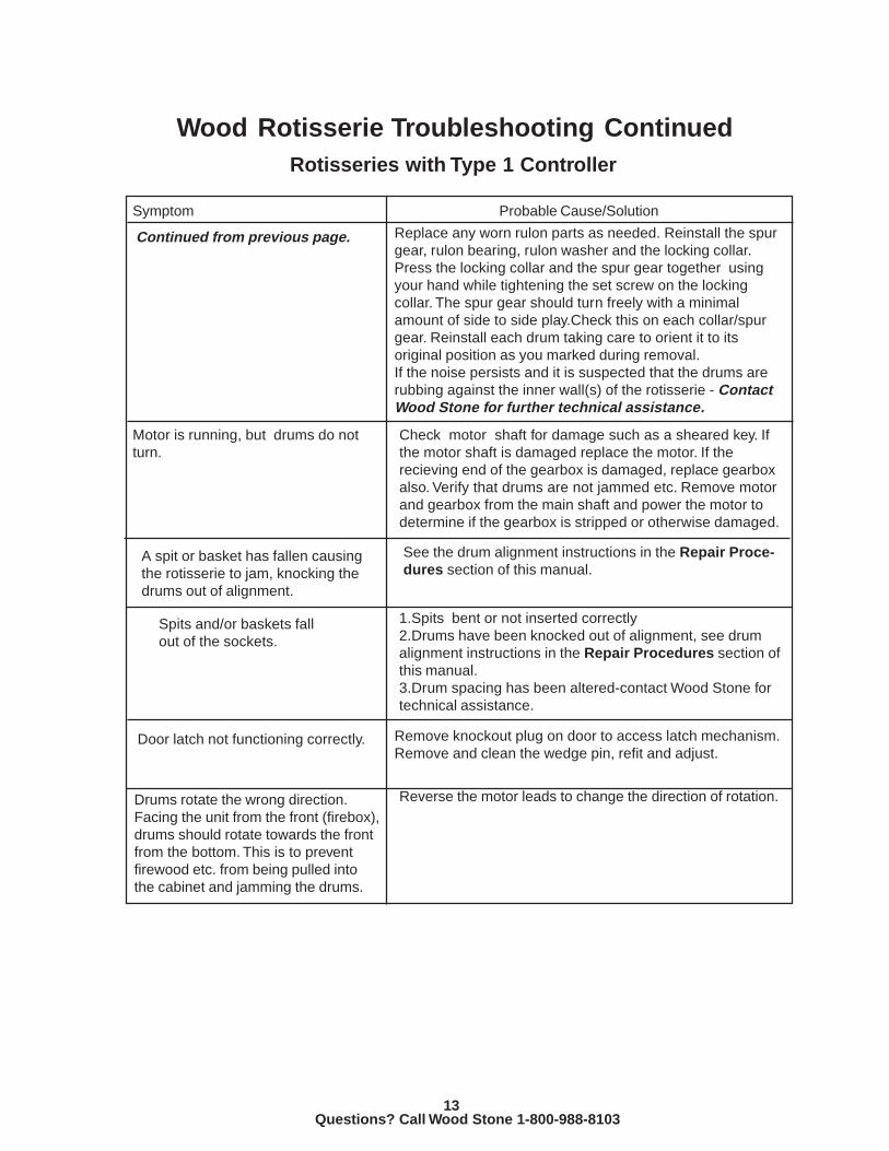
Continued from previous page. Replace any worn rulon parts as needed. Reinstall the spurgear, rulon bearing, rulon washer and the locking collar.Press the locking collar and the spur gear together usingyour hand while tightening the set screw on the lockingcollar. The spur gear should turn freely with a minimalamount of side to side play.Check this on each collar/spurgear. Reinstall each drum taking care to orient it to itsoriginal position as you marked during removal.If the noise persists and it is suspected that the drums arerubbing against the inner wall(s) of the rotisserie - ContactWood Stone for further technical assistance.
A spit or basket has fallen causingthe rotisserie to jam, knocking thedrums out of alignment.
See the drum alignment instructions in the Repair Proce-dures section of this manual.
Door latch not functioning correctly. Remove knockout plug on door to access latch mechanism.Remove and clean the wedge pin, refit and adjust.
Spits and/or baskets fallout of the sockets.
1.Spits bent or not inserted correctly2.Drums have been knocked out of alignment, see drumalignment instructions in the Repair Procedures section ofthis manual.3.Drum spacing has been altered-contact Wood Stone fortechnical assistance.
Motor is running, but drums do notturn.
Check motor shaft for damage such as a sheared key. Ifthe motor shaft is damaged replace the motor. If therecieving end of the gearbox is damaged, replace gearboxalso. Verify that drums are not jammed etc. Remove motorand gearbox from the main shaft and power the motor todetermine if the gearbox is stripped or otherwise damaged.
Drums rotate the wrong direction.Facing the unit from the front (firebox),drums should rotate towards the frontfrom the bottom. This is to preventfirewood etc. from being pulled intothe cabinet and jamming the drums.
Reverse the motor leads to change the direction of rotation.
Wood Rotisserie Troubleshooting Continued

14Questions? Call Wood Stone 1-800-988-8103
Wood Rotisserie Troubleshooting ContinuedRotisseries with Type 2 Controllers
Symptom Probable Cause/Solution
Drums do not turn when greenSTART switch is pushed , or whengreen START switch is held in. RedSTOP switch is not lit.
1. Power to outlet supplying power to the rotisserie is off, orbreaker at the electrical panel is tripped.2. Rotisserie power cord is not plugged in. The power cordconnects to the rotisserie via a twist lock connector on the bottomof the unit.3.Breaker on the rotisserie control panel is tripped. Reset thebreaker. If breaker trips again, find and correct the short and/oroverload condition.4. breaker on the 24VAC transformer has tripped. Transformer ismounted on the control plate inside the rotisserie. Unplug rotis-serie and remove the control panel to gain access to reset. Ifbreaker trips again find and correct short.5. Loose wire on control panel or control plate.
Breaker on electrical panel for thecircuit supplying the rotisserie trips.Breaker on the rotisserie is nottripped.
Power cord to rotisserie has been damaged, or problem with thecircuit breaker or wiring supplying the rotisserie outlet.
5 Amp breaker on rotisserie controlpanel trips immediately when STARTswitch is pushed. Breaker on trans-former has not tripped.
1.Check that there are no jammed spits or baskets etc. causing anoverload situation.2.Check for shorted motor windings. If motor has shorted to groundit may be necessary to replace the DC drive board as well. Checkthe wiring between the DC drive board and the motor for shorts.3. If motor checks out fine, check the 120v wiring leading from the5 Amp breaker to the relay and on to the DC drive board. Checkbreaker for signs of damage.4. If wiring and motor check fine, disconnect motor leads from theDC drive board. Then restart the unit. If breaker still trips discon-nect the incoming power to the drive board and retest. If breakerno longer trips with the drive board disconnected then the DCdrive board is bad.5.If breaker does not trip with motor disconnected, recheck motorfor shorts. If motor still checks okay, it will be necessary to verifythat the drum assembly is not jammed or binding. First, remove thedrive side drum. The drum is attached with 6 bolts. DO NOTLOOSEN THE 2” NUT ON THE SHAFT! Check for signs ofdamage on all of the gears. Verify that the ring gear position hasnot shifted, it should be centered with the shaft. If drum assemblyappears to be fine reassemble and proceed with step 6.Continued on next page.
Rotisserie does not turn when greenSTART button is pushed and re-leased, but does turn when greenSTART button is held in.
1. Rotisserie doors are not closed.2.Door switch is out of adjustment or damaged. See RepairProcedures section of this manual.3.Relay on control plate is loose. Reinsert the relay into its socketand secure with the retaining clip.
NOTE: If DC drive board is re-placed, refer to the set up instruc-tions found in the Repair Proce-dures section of this manual.
CAUTION! Disconnect power cordbefore removing control panel.Highvoltage is present at the terminalstrip on the back of the controlpanel, at the terminal strip on thecontrol plate, at the relay on thecontrol plate and at the DC driveboard on the control plate.
CAUTION! Disconnect power cordbefore removing control panel.Highvoltage is present at the terminalstrip on the back of the controlpanel, at the terminal strip on thecontrol plate, at the relay on thecontrol plate and at the DC driveboard on the control plate.

15Questions? Call Wood Stone 1-800-988-8103
Wood Rotisserie Troubleshooting ContinuedRotisseries with Type 2 Controllers
Symptom Probable Cause/Solution
Continued from previous page.
2. If 120VAC is present at L1 and L2 on the DC drive board,check wiring and wiring connections to the motor. If there isevidence that the wiring or motor are or have been shorted toground, the DC drive board could be damaged and may need tobe replaced. Checking at the motor leads,verify that the motorwindings are not open. Check the motor brushes, especially if themotor is mounted below the gear box. If there is no continuitythrough the motor leads or if gear oil has leaked into the motor,replace the motor. On rotisseries with the motor installed belowthe gearbox Wood Stone recommends that the gear box and themotor be reoriented so the motor is above the gear box. This willeliminate the possibility of oil leakage into the motor. See theRepair Procedures section of this manual. NOTE: If the wind-ings are open on the motor, the output voltage from the DC drivewill be low or non-existent. This is normal and in itself does notindicate a failed DC drive.3. If motor checks out fine, verify that the potentiometers on theDC drive board are set correctly, see the DC drive set up instruc-tions in the Repair Procedures section of this manual.4. If DC drive potentiometer settings are correct, and there is NOoutput voltage(DC) from the DC drive, replace the DC driveboard. If the motor has shorted to ground, the DC drive board mayalso be damaged. If the motor has not shorted to groundand there is 120vac power to the DC drive board, most likelyonly the motor itself is damaged and not the DC driveboard.
1.Loose wire connection or loose relay. After START button ispushed, test for 120VAC at L1 and L2 terminals on the DCdrive board. CAUTION-HIGH VOLTAGE IS PRESENT AT THEDC DRIVE BOARD, THE TERMINAL STRIP ON THE CON-TROL PANEL, AND AT THE TERMINAL STRIP AND RELAYON THE CONTROL PLATE.
6. Remove the motor from the rotisserie. Remove the key fromthe motor shaft. With the motor removed from the gear box,reattach the motor leads and run the motor-if breaker tripsreplace the motor. If motor runs, remove the gearbox andattach it to the motor to check if the gear box is binding orjammed. At this point the drums may be turned by hand tocheck for binding etc.
Drums do not turn when greenSTART button is pushed or held in,Green START button is lit.

16Questions? Call Wood Stone 1-800-988-8103
Wood Rotisserie Troubleshooting ContinuedRotisseries with Type 2 Controllers
Symptom Probable Cause/Solution
Replace any worn rulon parts as needed. Reinstall the spurgear, rulon bearing, rulon washer and the locking collar. Pressthe locking collar and the spur gear together using your handwhile tightening the set screw on the locking collar. The spurgear should turn freely with a minimal amount of side to sideplay.Check this on each collar/spur gear. Reinstall each drumtaking care to orient it to its original position as you markedduring removal.If the noise persists and it is suspected that the drums arerubbing against the inner wall(s) of the rotisserie - ContactWood Stone for further technical assistance.
A spit or basket has fallen causing therotisserie to jam, knocking the drumsout of alignment.
See the drum alignment instructions in the Repair Proceduressection of this manual.
Spits and/or baskets fall out of thesockets.
1.Spits bent or not inserted correctly2.Drums have been knocked out of alignment, see drum align-ment instructions in the Repair Procedures section of thismanual.3.Drum spacing has been altered-contact Wood Stone fortechnical assistance.
Door latch not functioning correctly. Remove knockout plug on door to access latch mechanism.Remove and clean the wedge pin, refit and adjust.
Drums rotate the wrong direction.Facing the unit from the front (firebox),drums should rotate towards the frontfrom the bottom. This is to preventwood etc. from being pulled into thecabinet and jamming the drums.
Reverse the motor leads to change the direction of rotation.
1. Debris has accumulated behind the drums. Mark the orienta-tion of each drum, then remove the 6 bolts holding each drum inplace. Do not loosen the 2” nut on the shaft! Remove anygrease/creosote buildup. On the drive side inspect the rulonwear buttons on the spur gears, and the rulon washers andbushings. If the rulon bearing turns freely in the drum sleeve,remove the spur gear and the rulon bearing then use a punch todimple the metal drum sleeve. The rulon bushing should not turnwhen the gear rotates.
Abnormal sounds coming from drums.
Motor is running, but drums do not turn. Check motor shaft for damage such as a sheared key. If themotor shaft is damaged replace the motor. If the recieving endof the gearbox is damaged, replace gearbox also. Verify thatdrums are not jammed etc.
1.Check for loose or damaged potentiometer leads.2.Replace speed potentiometer. If speed potentiometer is good,replace the control board.
Speed control knob has no effect on thespeed of the drums.

17Questions? Call Wood Stone 1-800-988-8103
Wood Rotisserie Type 1 ControllerWiring Diagram
Jumper LocationsJ200 - jumper 1 and 2J3 - jumper 1 and 2J5 - jumper 9 and 10
Settingsmax potentiometer is 90 vdc (with motor connected)min potentiometer is 30vdc (with motor connected)current limit adjusted to fullrate adjusted to 75% of full

18Questions? Call Wood Stone 1-800-988-8103
Wood Rotisserie Type 2 Controller Wiring Diagram
DC Drive Board SettingsSet the two incoming ac voltage selector switches to the appropriate position-U.S. units are 115vac.Set the dc output voltage to 90vdcMIN SPD potentiometer-adjust to 30vdc output with the motor connected.MAX SPD potentiometer-adjust to 90vdc output with the motor connected.ACCEL potentiometer- adjust to full and then back 1/4 turn.DECEL potentiometer- adjust to full then back 1/4 turn.TORQUE potentiometer - adjust to full then back 1/4 turn.IR COMP potentiometer - adjust to full then back 1/2 turn.

19Questions? Call Wood Stone 1-800-988-8103
GFR - Gas Fired Rotisseries-Operation annd Components
Operational OverviewComponents: Electrical and Control, Drive System, Gas System, WaterOperation sequenceGFR with Montague Broiler option

20Questions? Call Wood Stone 1-800-988-8103
Gas Fired (GFR) RotisseriesWood Stone manufactures two models of gas fired rotisseries (GFR). They both use a direct drive system toturn the drums, the same type of system that is used in the wood rotisserie line. Both are equipped with aradiant and an infrared burner. Additionally, the second model is equipped with a broiler stand and Montaguebroiler installed on the front of the unit. Questions specifically regarding the Montague broiler should bedirected to the Montague Company at 1-800-345-1830. The rotisseries are essentially the same with theexception of a few minor differences to accomodate the broiler table on broiler equipped units.
GFR Operational Overview
The GFR models incorporate two gas fired burners as heat sources. There is a radiant flame burner installedat the bottom of the main cabinet opening in the front of the unit. There is also an infrared burner installedabove the main cabinet opening. It is critical to the performance of the rotisserie that both of these burnersare working correctly. The radiant (lower) burner flame height is adjusted using the control knob mounted onthe front of the cabinet. The operator uses the flame height to control the cooking temperature.The radiantburner is engineered to produce a yellow flame-this is normal. The amber button activates the burners onlyafter the drums have been started by pushing the green button.The green button on the control panel starts the drums. The speed control knob on the front control panelallows adjustment of the drum speed. Pushing the red stop button shuts down the gas burners and stops thedrums.There is a door switch that prevents both the burners and the drums from running when the rear doors areopen. The operator can, however, ‘jog’ the drums by holding the green button down while the doors are opento facilitate loading product. On rotisseries that are not equipped with the charbroiler there is also a bump baron the front of the rotisserie that when pushed will prevent both the burners and the drums from running in thesame manner as the door switch.There is a water control knob on the front of the unit. The rotisserie drip pan must be filled with water whilethe rotisserie is running for safety reasons and to prevent warpage of the tray. The drain plug has an overflowfeature to prevent the pan from over filling.
GFR Components OverviewElectrical Control System
The GFR control system is comprised of two control panels - one mounted at the front of the rotisserie andone at the rear, and the control plate mounted inside the rotisserie drive compartment. Each control panel hasa red STOP button, a green button to start drum rotation, and an amber switch to start the burners. Addition-ally the drum speed control knob is located on the front control panel.All other rotisserie functions can becontrolled from either control panel. A 5 amp push button circuit breaker is located on the rear control panelfor the incoming 120vac power.The green button functions as a jog switch when the doors are open. NOTE:The GFR is also available with a single control panel. On this version the speed control and the circuitbreaker are both mounted on the one control panel.On the control plate inside the drive compartment are mounted a 24vac transformer, a terminal strip, tworelays, a dc drive board and two ignition modules. The dc drive board provides power to the dc motor. A doorswitch is mounted at the rear of the cabinet below the control panel. It is wired in such a way that only the jogfunction is enabled if the doors are open. A wire harness connects each control panel to the control plate. Onthe broiler equipped model, a cable and multi pin connector are used for the front control panel.

21Questions? Call Wood Stone 1-800-988-8103
GFR Operation Sequence
Rotisserie power cord plugged in.
Amber button pushed to activate burners-burners do not fire. Drums must be turning
before burner operation is allowed.
Doors closed. Bump bar not pushed.Green button pushed. 24 vac energizesand latches relay 1, allowing 120vac to
flow to the DC drive board, and 24vac tothe amber push button switch. DC driveboard supplies DC power to the motor.
Drums begin turning.
Amber button pushed. 24vac energizes andlatches relay 2, sending power to both
ignition modules.Each module powers itsrespective gas valve and spark igniter.
Burners light, modules detect flame rectifica-tion at the igniter and shut off spark to the
igniter. If a burner goes out or does not lightthe ignition module will again attempt to lightthe burner and then lock out. Turn off, then
restart the rotisserie to reset the ignitionmodules.
Pushing the red button stops drum rotationand turns off both burners. Also, openingdoors or pushing bump bar wil stop drum
rotation and turn off burners.
Doors open or bump bar is pushed,green button pushed. No action.
Drums can be jogged if green buttonis held in when the doors are open.

22Questions? Call Wood Stone 1-800-988-8103
Mechanical Drive SystemThe drive system on the gas rotisseries is identical to that on the wood rotisseries. Wood Stone rotisseries usa DC motor and gearbox to turn the rotisserie drums. Wood Stone has used different suppliers for motorsand gearboxes. All are interchangeable. If a gearbox is being replaced it will be necessary to know themanufacturer of the gearbox or have a description of it, so that we can supply any additional mountinghardware if necessary for the replacement.
Brother gearbox (gray) shown with BaldorMotor
Moorse gearbox (blue) shown with Leeson motor.
Drum ComponenentsDrum components on the gas fired rotisseries are identical to those used on the solid fuel (wood) rotisseries.See pages 8 and 9 in this manual.
23Questions? Call Wood Stone 1-800-988-8103
Gas System Components
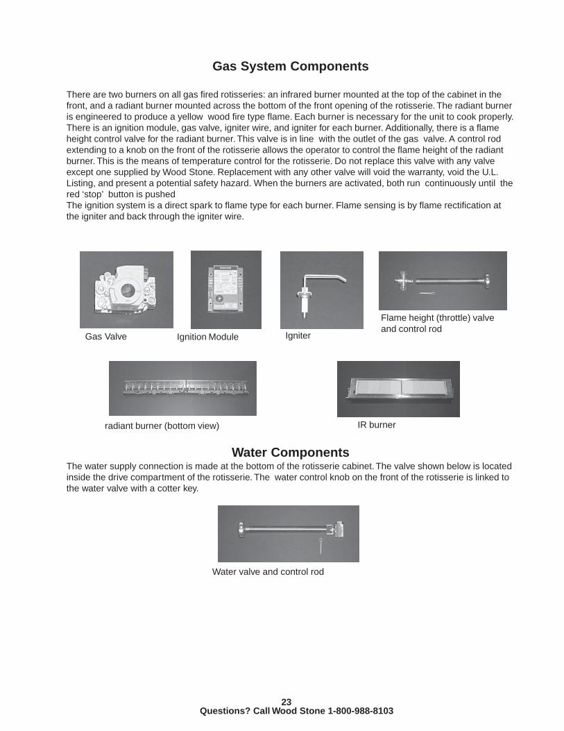
There are two burners on all gas fired rotisseries: an infrared burner mounted at the top of the cabinet in thefront, and a radiant burner mounted across the bottom of the front opening of the rotisserie. The radiant burneris engineered to produce a yellow wood fire type flame. Each burner is necessary for the unit to cook properly.There is an ignition module, gas valve, igniter wire, and igniter for each burner. Additionally, there is a flameheight control valve for the radiant burner. This valve is in line with the outlet of the gas valve. A control rodextending to a knob on the front of the rotisserie allows the operator to control the flame height of the radiantburner. This is the means of temperature control for the rotisserie. Do not replace this valve with any valveexcept one supplied by Wood Stone. Replacement with any other valve will void the warranty, void the U.L.Listing, and present a potential safety hazard. When the burners are activated, both run continuously until thered ‘stop’ button is pushedThe ignition system is a direct spark to flame type for each burner. Flame sensing is by flame rectification atthe igniter and back through the igniter wire.
Gas Valve Ignition Module Igniter
Flame height (throttle) valveand control rod
radiant burner (bottom view) IR burner
Water ComponentsThe water supply connection is made at the bottom of the rotisserie cabinet. The valve shown below is locatedinside the drive compartment of the rotisserie. The water control knob on the front of the rotisserie is linked tothe water valve with a cotter key.
Water valve and control rod

24Questions? Call Wood Stone 1-800-988-8103
Broiler Equipped RotisseriesThere are a few differences between the broiler equipped GFRs and the standard GFR.The standard GFR incorporates a bump bar across the front of the rotisserie. It is a safety device that will shutdown the drums and the burners if it is pushed. On broiler equipped rotisseries the broiler is located directly infront of the rotisserie, so a bump bar is not necessary and therefore not installed on these units.On broiler equipped models you will find that the front rotisserie control panel is installed on the front of thebroiler table. This control panel is connected to the rotisserie with a multi-conductor cable using a multi-pinlocking connector at the control panel. This makes it possible to separate the broiler table from the mainrotisserie for service. The controls for water and flame height are also located at the front of the broiler table.The control rods pass through to the rotisserie where they connect to the corresponding valves.The broilertable is bolted at the bottom to the rotisserie using two connecting plates. The broiler uses a gas supply andconnection that is completely separate from the rotisserie. Questions concerning the broiler itself should bedirected to the Montague Company at 1-800-345-1830.
IMPORTANTTHE GAS REGULATOR THAT IS SUPPLIED WITH THE MONTAGUE BROILER MUST BE INSTALLED ANDADJUSTED AS SPECIFIED IN THE INSTALLATION INSTRUCTIONS SUPPLIED WITH THE BROILER.FAILURE TO PROPERLY INSTALL AND ADJUST THE BROILER CAN CAUSE SEVERE DAMAGE TOTHE ROTISSERIE AND THE BROILER AND MAY VOID THE WARRANTY.

25Questions? Call Wood Stone 1-800-988-8103
GFR - Gas Fired RotisserieTroubleshooting
Electrical and Drive System TroubleshootingGas System and Burner TroubleshootingWiring Diagrams

26Questions? Call Wood Stone 1-800-988-8103
Gas Fired Rotisserie Troubleshooting
The troubleshooting guide for the gas rotisseries will be broken into two sections. The first will cover theElectrical and Drive Systems. You will find most of the information in this section to be identical to that for theWood Rotisserie with the Type 2 controller, found earlier in this manual.The second section will cover the GasBurners.
Gas Fired Rotisserie-Electrical and Drive System Troubleshooting
Symptom Probable Cause/Solution
Drums do not turn when green STARTswitch is pushed, or when green STARTswitch is held in. Red STOP switch is not lit.
1. Power to outlet supplying power to the rotis-serie is off, or breaker at the electrical panel istripped.2. Rotisserie power cord is not plugged in. Thepower cord connects to the rotisserie via a twistlock connector on the bottom of the unit.3.Breaker on the rotisserie control panel istripped. Reset the breaker. If breaker trips again,find and correct the short and/or overload condi-tion.4. Breaker on the 24VAC transformer has tripped.Transformer is mounted on the control plate insidethe rotisserie. Remove the side panel to gainaccess to reset. If breaker trips again find andcorrect short.5. Loose wire on control panel or control plate.
Breaker on electrical panel for the circuitsupplying the rotisserie trips. Breaker on therotisserie is not tripped.
Power cord to rotisserie has been damaged, orproblem with the circuit breaker or wiring supplyingthe rotisserie outlet.
Rotisserie does not turn when green STARTbutton is pushed, but does turn when greenSTART button is held in.
1. Rotisserie doors are not closed.2.Bump bar is pushed in.3.Door switch or bump bar switch is out of adjust-ment or damaged. See Repair Procedures sectionof this manual.4.Relay on control plate is loose. Reinsert the relayinto its socket and secure with the retaining clip.
5 Amp breaker on rotisserie control paneltrips immediately when START switch ispushed. Breaker on transformer has nottripped.
NOTE: If DC drive board is replaced, refer tothe set up instructions found in the RepairProcedures section of this manual.
1.Check that there are no jammed spits or basketsetc. causing an overload situation.2.Check for shorted motor windings. If motor hasshorted to ground it may be necessary to replace theDC drive board as well. Check the wiring betweenthe DC drive board and the motor for shorts.3. If motor checks out fine, check the 120v wiringleading from the 5 Amp breaker to the relay4. If wiring and motor check fine, disconnect motor
Continued on next page.
27Questions? Call Wood Stone 1-800-988-8103
GFR Electrical and Drive System Troubleshooting Continued
Symptom Probable Cause/Solution
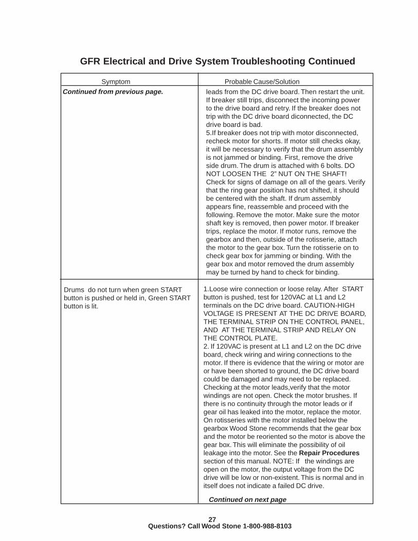
leads from the DC drive board. Then restart the unit.If breaker still trips, disconnect the incoming powerto the drive board and retry. If the breaker does nottrip with the DC drive board diconnected, the DCdrive board is bad.5.If breaker does not trip with motor disconnected,recheck motor for shorts. If motor still checks okay,it will be necessary to verify that the drum assemblyis not jammed or binding. First, remove the driveside drum. The drum is attached with 6 bolts. DONOT LOOSEN THE 2” NUT ON THE SHAFT!Check for signs of damage on all of the gears. Verifythat the ring gear position has not shifted, it shouldbe centered with the shaft. If drum assemblyappears fine, reassemble and proceed with thefollowing. Remove the motor. Make sure the motorshaft key is removed, then power motor. If breakertrips, replace the motor. If motor runs, remove thegearbox and then, outside of the rotisserie, attachthe motor to the gear box. Turn the rotisserie on tocheck gear box for jamming or binding. With thegear box and motor removed the drum assemblymay be turned by hand to check for binding.
Continued from previous page.
Drums do not turn when green STARTbutton is pushed or held in, Green STARTbutton is lit.
1.Loose wire connection or loose relay. After STARTbutton is pushed, test for 120VAC at L1 and L2terminals on the DC drive board. CAUTION-HIGHVOLTAGE IS PRESENT AT THE DC DRIVE BOARD,THE TERMINAL STRIP ON THE CONTROL PANEL,AND AT THE TERMINAL STRIP AND RELAY ONTHE CONTROL PLATE.2. If 120VAC is present at L1 and L2 on the DC driveboard, check wiring and wiring connections to themotor. If there is evidence that the wiring or motor areor have been shorted to ground, the DC drive boardcould be damaged and may need to be replaced.Checking at the motor leads,verify that the motorwindings are not open. Check the motor brushes. Ifthere is no continuity through the motor leads or ifgear oil has leaked into the motor, replace the motor.On rotisseries with the motor installed below thegearbox Wood Stone recommends that the gear boxand the motor be reoriented so the motor is above thegear box. This will eliminate the possibility of oilleakage into the motor. See the Repair Proceduressection of this manual. NOTE: If the windings areopen on the motor, the output voltage from the DCdrive will be low or non-existent. This is normal and initself does not indicate a failed DC drive.
Continued on next page
28Questions? Call Wood Stone 1-800-988-8103
GFR Electrical and Drive System Troubleshooting ContinuedSymptom Probable Cause/Solution
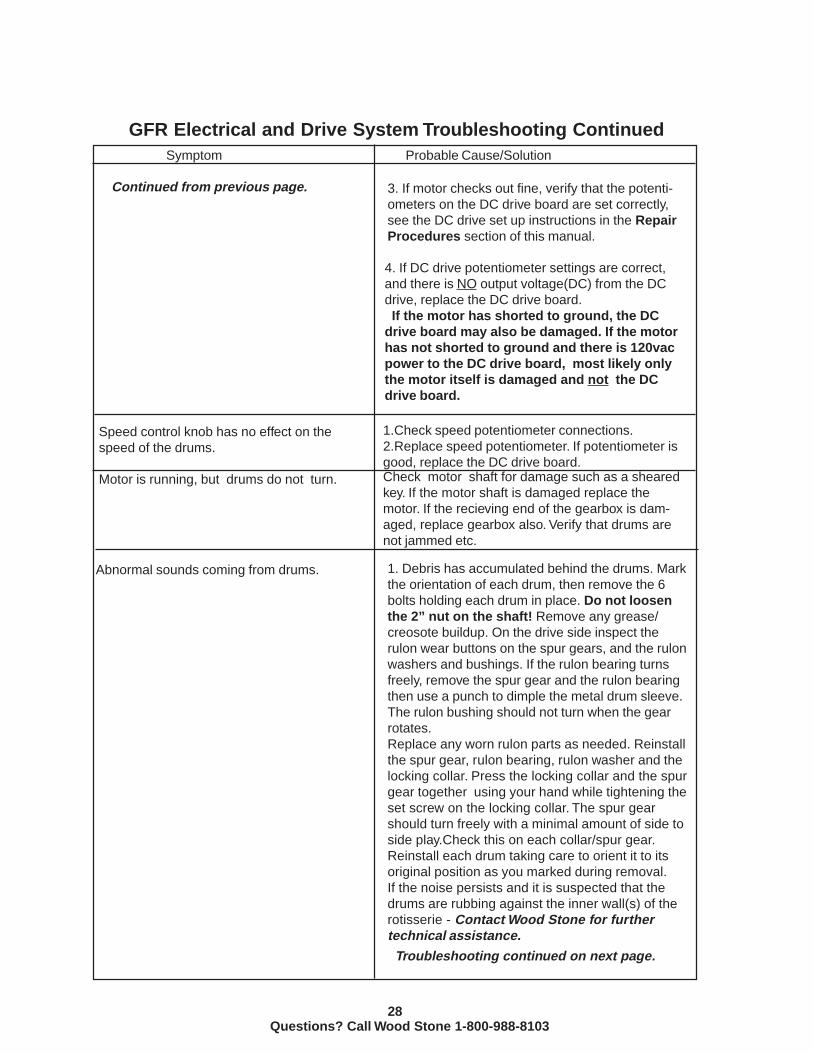
Continued from previous page.
4. If DC drive potentiometer settings are correct,and there is NO output voltage(DC) from the DCdrive, replace the DC drive board. If the motor has shorted to ground, the DCdrive board may also be damaged. If the motorhas not shorted to ground and there is 120vacpower to the DC drive board, most likely onlythe motor itself is damaged and not the DCdrive board.
Speed control knob has no effect on thespeed of the drums.
1.Check speed potentiometer connections.2.Replace speed potentiometer. If potentiometer isgood, replace the DC drive board.
Motor is running, but drums do not turn. Check motor shaft for damage such as a shearedkey. If the motor shaft is damaged replace themotor. If the recieving end of the gearbox is dam-aged, replace gearbox also. Verify that drums arenot jammed etc.
Abnormal sounds coming from drums. 1. Debris has accumulated behind the drums. Markthe orientation of each drum, then remove the 6bolts holding each drum in place. Do not loosenthe 2” nut on the shaft! Remove any grease/creosote buildup. On the drive side inspect therulon wear buttons on the spur gears, and the rulonwashers and bushings. If the rulon bearing turnsfreely, remove the spur gear and the rulon bearingthen use a punch to dimple the metal drum sleeve.The rulon bushing should not turn when the gearrotates.Replace any worn rulon parts as needed. Reinstallthe spur gear, rulon bearing, rulon washer and thelocking collar. Press the locking collar and the spurgear together using your hand while tightening theset screw on the locking collar. The spur gearshould turn freely with a minimal amount of side toside play.Check this on each collar/spur gear.Reinstall each drum taking care to orient it to itsoriginal position as you marked during removal.If the noise persists and it is suspected that thedrums are rubbing against the inner wall(s) of therotisserie - Contact Wood Stone for furthertechnical assistance.
Troubleshooting continued on next page.
3. If motor checks out fine, verify that the potenti-ometers on the DC drive board are set correctly,see the DC drive set up instructions in the RepairProcedures section of this manual.

29Questions? Call Wood Stone 1-800-988-8103
GFR Electrical and Drive System Troubleshooting ContinuedSymptom Probable Cause/Solution
Spits and/or baskets fall out of thesockets.
1.Spits bent or not inserted correctly.2.Drums have been knocked out of alignment, seedrum alignment instructions in the Repair Proce-dures section of this manual.3.Drum spacing has been altered-contact WoodStone for technical assistance.
Door latch not functioning correctly. Remove knockout plug on door to access latchmechanism. Remove and clean the wedge pin, refitand adjust.
Drums rotate the wrong direction. Facingthe unit from the front (open side), drumsshould rotate towards the front from thebottom.
Reverse the motor leads to change the direction ofrotation.
See drum alignment instructions in the RepairProcedures section of this manual.
A spit or basket has fallen causing therotisserie to jam, knocking the drums outof alignment.

30Questions? Call Wood Stone 1-800-988-8103
GFR Gas Burner TroubleshootingSymptom Probable Cause/Solution
Neither burner lights, no sparking soundheard from the igniters.
1. Drums must be turning before control will allow burneroperation.2. Loose wire at either control panel or the control plate.3. Amber switch is damaged.3.#2 relay loose.4.Check igniter and ignition module connections, checkigniters for damage. Check fuses on ignition modules.
Neither burner lights, but a sparking soundcan be heard from each igniter.
Gas supply not connected. Air has not been bled out ofthe gas line supplying the rotisserie. Gas valves in therotisserie turned off.
One burner does not light. 1.Loose igniter wire.2.Igniter is broken. Visually check for spark. Open reardoor and hold door switch in. Turn on drums andburners. You should see spark between the two probesof the igniter. Make sure the igniter is not sparking tothe rotisserie cabinet or burner shield. If the igniter issparking to the cabinet or shield, make sure that theigniter is properly positioned. Note that while testing theburners with the rear door(s) open that any negativeairflow to the rear of the cabinet may have an effect onthe lighting characteristis of the burners and/origniters.Loosen the mounting screws to reposition theigniter. If the igniter is sparking to the radiant burnershield, verify that the shield is properly positioned andnot bent. Position and rebend the shield as necessary.If it is necessary to adjust the probes on the igniter,carefully bend only the non-insulated probe. Do notattempt to bend the probe with the ceramic insula-tor. If probes move freely or ceramic insulator iscracked or broken, replace the igniter.3.Fuse blown on ignition module. Check the wiring tothe gas valve and the gas valve itself for shorts.4.Insufficient gas pressure. Verify correct pressure atthe valve outlet and adjust as necessary. If incominggas pressure is sufficient, but pressure at the outlet ofthe valve is low, verify 24vac to the valve. If voltage isgood replace the valve.5. Excessive airflow through the rotisserie. Consult aqualified HVAC installer to check that the exhaust fanfor the hood is pulling the correct amount of air and/or ifthere are other air balance and ventilation issues in thefacility. Wood Stone will not be responsible for anyproblems stemming from improper ventilation or airbalance.
Long cook times. 1.Low incoming gas pressure, and/or burner pressuresset too low. Check and adjust to pressure specified on thedata plate.2.Excessive airflow.3.Operational problems-contact Wood Stone.
Burned wiring and/or heat damage toigniter and/or other electrical components..Exceesive carbon buildup on radiantburner.
1.Check for loose burner jet(s) or crackedmanifold.2.Improper air balance causing heat from theburner to be pulled into the drive compartment3.Charbroiler incorrectly installed, adjusted oroperated (on charbroiler equipped units only).

31Questions? Call Wood Stone 1-800-988-8103
GFR Electrical Diagrams

32Questions? Call Wood Stone 1-800-988-8103

33Questions? Call Wood Stone 1-800-988-8103
DC Drive Board SettingsSet the two incoming ac voltage selector switches to the appropriate position-U.S. units are 115vac.Set the dc output voltage to 90vdcMIN SPD potentiometer-adjust to 30vdc output with the motor connected.MAX SPD potentiometer-adjust to 90vdc output with the motor connected.ACCEL potentiometer- adjust to full and then back 1/4 turn.DECEL potentiometer- adjust to full then back 1/4 turn.TORQUE potentiometer - adjust to full then back 1/4 turn.IR COMP potentiometer - adjust to full then back 1/2 turn.

34Questions? Call Wood Stone 1-800-988-8103
SFR and GFR Repair ProceduresCommon Repair Procedures

35Questions? Call Wood Stone 1-800-988-8103
Repair ProceduresPotentiometer Replacement
Disconnect the power to the rotisserie before proceeding. A soldering iron and solder are neces-sary for the installation of the new potentiometer. Check the orientation of the wires on the originalpotentiometer and the control board and install the new potentiometer accordingly. Make sure the terminalson the potentiometer are bent safely away from the control panel to prevent the leads from shorting toground.
Type 1 Controller - Switch ReplacementDisconnect power to the rotisserie before proceeding. Note: do not replace this switch except with oneprovided by Wood Stone. Failure to do so can damage the controller.Orient the new switch the samedirection as the original. Replace the switch boot if it is damaged. Repair any damaged connectors or wiring asnecessary.
Type 2 Controller - Switch ReplacementDisconnect power to the rotisserie before proceeding.To remove the old switch first unscrew and removethe colored lense. Then unscrew the mounting ring and remove the switch from the back of the control panel.
Type 2 Controller - Switch Indicator Lamp ReplacementDisconnect power to the rotisserie before proceeding.Follow the instructions above for removal of theswitch. Once the switch is removed, lift the tabs on the switch, closest to the front of the switch. Separate theback from the front to access the lamp. Replace with a 24volt 1w - M type bulb.
Igniter Replacement-GFR RotisseriesRadiant burner (lower) - Lift the burner shield off of the rotisserie. Disconnect the igniter wire from the igniter.Remove machine screw and nut that hold the igniter to the mounting bracket. Remove the igniter. Install thenew igniter so it is oriented in the same direction as the old one. Caution: The igniter is fragile-do not bendthe probes on the igniter! In some units it may be necessary to slightly bend the igniter bracket to get thenew igniter in place. If this is necessary, be sure to bend the bracket back to its original position beforeproceeding. Reconnect the igniter wire. Put the burner shield back in place and test the unit. If the burner doesnot light pproperly, make sure that the igniter is not sparking to either the burner shield, or the deflector on theburner itself. Reposition the igniter in thhe bracket, and /or bend the shield or deflector slightly to correct theproblem. Theigniter should spark between its two probes. Do not bend the igniter probes.Infrared Burner (upper) - Remove the upper front panel on the rotisserie. Disconnect the igniter wire.Remove the screws holding the igniter in place. Install the new igniter so it is oriented in the same direction asthe old one.
Gas Pressures - Checking and AdjustingGas pressure readings are taken at the outlet port on the gas valve for each burner. Make sure that bothburners are lit, and that the radiant flame control knob is turned all the way up(full counter-clockwise). Removethe side panels on the drive side of the rotisserie to access the gas valves. The valves may also be accessedby removing the rear louver panel, if the side panels are not readily removeable.Valve outlet pressures should be as follows:NaturalGas - 4” W.C. for each burner.LP - 8” W.C. for each burner.If necessary, adjust the gas valve to obtain the correct pressure. Remove the cap (flat blade) at the inlet sideof the valve to access the adjustment screw. Turn clockwise to increase pressure. Make sure to replace thecap once the adjustment is complete.
Door Switch AdjustmentRemove the rear louver panel to access the door switch. The switch is mounted on a slotted bracket. Loosenthe bolts that attach the switch to the bracket. Slide the switch on the bracket to the point where you can hearthe actuator click when the door is closed, but at the same time positioned so the actuator rod is notcompletely bottoming out against the switch. This will help prevent the switch from wearing out prematurely.Tighten the mounting bolts and recheck the switch positioning.
36Questions? Call Wood Stone 1-800-988-8103
Disconnect power to the rotisserie before proceeding. If you are replacing a motor that is currently posi-tioned below the gearbox, it will be necessary to reorient the motor and gearbox so that the motor is above thegearbox. This will help prevent future motor failures if oil leakage from the gearbox occurs.See the GearboxReorientation instructions later in this section.First, disconnect the power leads at the box on the motor itself. On units equipped with the blue Moorsegearbox it will then be possible to simply remove the motor mounting bolts to remove the motor. On unitsequipped with thhe silver Brother gearbox it will be necessary to unbolt the torque arm that connects thegearbox to the mounting bracket. Be careful - the gearbox and motor are heavy. With the torque armdisconnected, tilt the motor and gearbox towards the front of the rotisserie and allow it to rest on the forwardsupport bracket. The motor may now be unbolted and removed. Apply a small amount of grease to the shaftkey and keyway of the new motor. Position the key so it protrudes slightly beyond the tip of the motor shaftbefore positioning it into the gearbox. Bolt the new motor to the gearbox. Position the gearbox and motor andreconnect the torque arm. Reconnect the power leads to the motor. Connect the power to the rotisserie andcheck the motor rotation. From the bottom, the drums should rotate towards the front of the rotisserie. Reversethe motor leads to change the direction of rotation if necessary.
Motor Replacement
Bump Bar Switch AdjustmentFirst disconnect the power to the rotisserie.To access the bump bar switch remove the front control panel.Bend the actuator rod to achieve the correct angle so the bump bar engages the switch when it is in its restingposition. The actuator rod should not hang up in the slot when the bump bar is pushed.
Type 1 Controller ReplacementDisconnect incoming power to the rotisserie before proceeding. The Type 1 controller is found only onsome SFR (woodfired) rotisseries. The Type 1 control is a self contained unit housed in a white steel box.After the power is disconnected, open up the white control box. Some units will have a bezel that will need tobe removed before the control can be opened.1.Disconnect the incoming power leads at L1 andL2/F1 on the upper terminal strip. Also disconnect the greenground wire.2.Disconnect the motor leads at A1and A2/F2 on the upper terminal strip. Also disconnect the green groundwire from the motor.3.Disconnect the door switch leads at the wire nut and at 32 on the lower terminal strip.4.Remove the side panel to access the back of the controller. Remove all conduit from the controller. Save theconduit fittings to reuse on the new control.5.Loosen the 2 bolts that attach the control box to the mounting brackets and remove the control fromtherotisserie. Mount the new control box onto the brackets.6. Reattach conduit to the new control and connect wiring as it was on the old control. See steps 1-3.7. Verify thhese settings on the new control.Jumper Locations : J 200 -jumper 1 and 2, J 3 - jumper 1 and 2, J 5 - jumper 9 and 10.Settings: Current limit - full, Rate - 75% of full. Max potentiometer set to 90VDC with motor connected. MinPotentiometer - Set to 30VDC with motor connected.
Type 2 Control ReplacementDisconnect power to the rotisserie before proceeding. On SFR rotisseries access the control plate byremoving the control panel at the back of the rotisserie. On GFR rotisseries access is through the side panelon the drive side of the rotisserie.Note the positioning of the wire connections on the control board. Wiring connections must be exactlythe sameas they were on the old board to ensure correct motor rotation and proper function of the speed pot.
Type 2 DC Drive Board SettingsSet the two incoming ac voltage selector switches to the appropriate position-U.S. units are 115vac.Set the dc output voltage to 90vdcMIN SPD potentiometer-adjust to 30vdc output with the motor connected.MAX SPD potentiometer-adjust to 90vdc output with the motor connected.ACCEL potentiometer- adjust to full and then back 1/4 turn.DECEL potentiometer- adjust to full then back 1/4 turn.TORQUE potentiometer - adjust to full then back 1/4 turn.IR COMP potentiometer - adjust to full then back 1/2 turn.

37Questions? Call Wood Stone 1-800-988-8103
Gearbox Reorientation Procedure1. Turn off power to the rotisserie either by unplugging it or turning it off at the main breaker panel.2. Remove the side covers on the controller side of the rotisserie cabinet to gain access to the motor andgeardrive.3.Remove the motor junction box cover, disconnect the motor leads, and disconnect the flexible conduit fromthe motor. Remove the 4 bolts retaining the motor to the geardrive and remove the motor.4.Drain the oil from the gearbox by placing a collection pan under the gearbox and removing the drain plug.Retain the oil for reuse or replace the oil. Synthetic 90-weight oil should be used.5.Loosen the gearbox collar set screws to the main shaft using a 5/32” Allen head wrench.6.Disconnect the torque arm from the torque arm bracket by removing the single bolt, nut and lock washer andsave these for reassembly.7.Remove the vent plug from the top of the gear drive and install a solid drain plug. Save the vent plug forreuse during reassembly.8. Remove the gearbox assembly by sliding the complete unit off of the main shaft. Caution! The gearboxassembly weighs over 80 lbs. Care should be taken to prevent injury. Get assistance if necessarywhen removing or installing the gearbox.9. Remove the bolts retaining the torque arm to the gearbox and remove the torque arm. Keep these bolts forreuse.10. Remove the short bolts from the opposite gearbox flange and install the torque arm on this flange using thelonger bolts removed with the torque arm.11. Replace the short bolts in the flange from which the torque arm was removed.12. Refill the gearbox and top off the lubricant.13.Install the vent plug in the uppermost vent opening.14. Remove the 6” key from the keyway on the main shaft.15. Lift the gearbox assembly and slide it onto the shaft with the motor flange above the gearbox and thetorque arm to the inside of the cabinet. Slide the assembly on until it bottoms on the shaft, then replace thebolt, nut and lock washer through the torque arm and bracket and tighten.16. Reinstall the motor. Note that if this is a new motor it may appear different from the one removed but it isdirectly interchangeable. To prevent the key from binding in the motor shaft, start the shaft into the reciever ofthe geardrive with the key half way off of the end of the motor shaft.17. Remove the fill plug from the top of the gearbox, and remove the level check plug from the side of thegearbox. If necessary, add synthetic 90 weight gear oil to bring the fluid level up to the level plug and reinstallthe level plug.18. Install the vented plug removed in step 6 in the fill hole on top of the gearbox. NOTE: Do not install thenon-vented plug as this will cause gearbox seal failure!19. Turn the drum assembly until the keyways in the shaft and the gearbox line up, then slip the key in and
Gearbox ReplacementDisconnect power to the rotisserie before proceeding. Follow the instructions above for removing themotor. On Moorse gearboxes (blue) loosen the shaft set screws, on Brother gearboxes (gray) remove theretaining collar from the shaft. Caution-the gearbox is heavy. Slide the gearbox off of the shaft to remove it.The Brother gearbox (gray) is the current factory replacement. If you are replacing a Brother gearbox simplyreverse the removal procedure to install the new one.Replacing a Moorse (blue) gearbox with the Brother gearbox requires the installation of a different torque arm,and a retaining collar (both supplied by Wood Stone). The key on the main rotisserie shaft will need to be cutto accomodate the retaining collar.The torque arm is bolted to the same bracket as the old gearbox. You may want to loosen this mountingbracket to allow for easier installation of the torque arm. Swing the gearbox up into position, do not attach themotor at this time. Then bolt the torque arm to the gearbox, attaching it at the lower mounting hole on thegearbox. Slide the gearbox inward on the shaft so the torque arm and mounting bracket are square (perpen-dicular to the shaft). Lightly tighten the torque arm bracket and torque arm mounting bolts. Make a mark on theshaft key even with the outer edge of the gearbox where it meets the shaft. Remove the gearbox, then removethe shaft key and using a cut off grinder cut it on the mark. Use a file to smooth the cut edges. Apply amoderate coating of grease to the key, keyway and shaft. Reinstall the key. Then slide the gearbox onto theshaft. Attach the motor and tilt the gearbox and motor into position. Reattach the torque arm. Tighten the boltson the torque arm bracket and torque arm. Slide the retaining collar onto the shaft, up against the gearbox andtighten the set screw.
Continued on next page.
38Questions? Call Wood Stone 1-800-988-8103
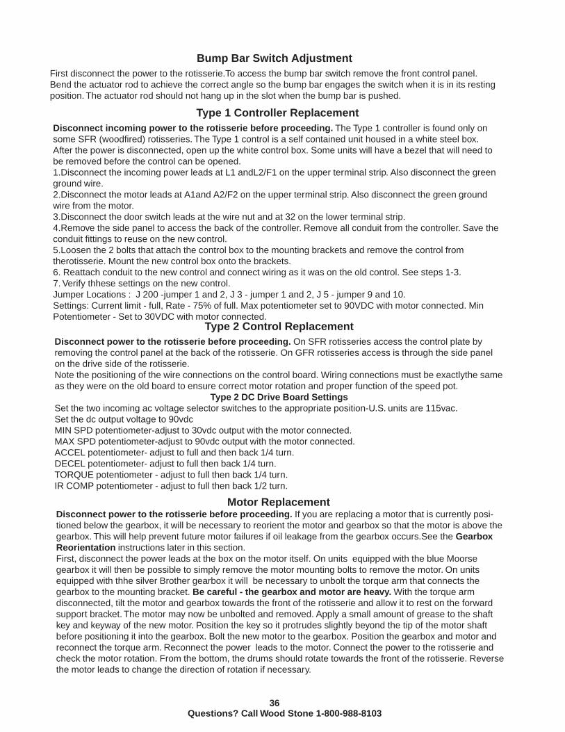
Geardrive with motor positioned below the gearbox.If the unit you are working on has the motor in the downside position (as above), it should be reoriented as
described on the previous page.
Torque ArmVent Plug
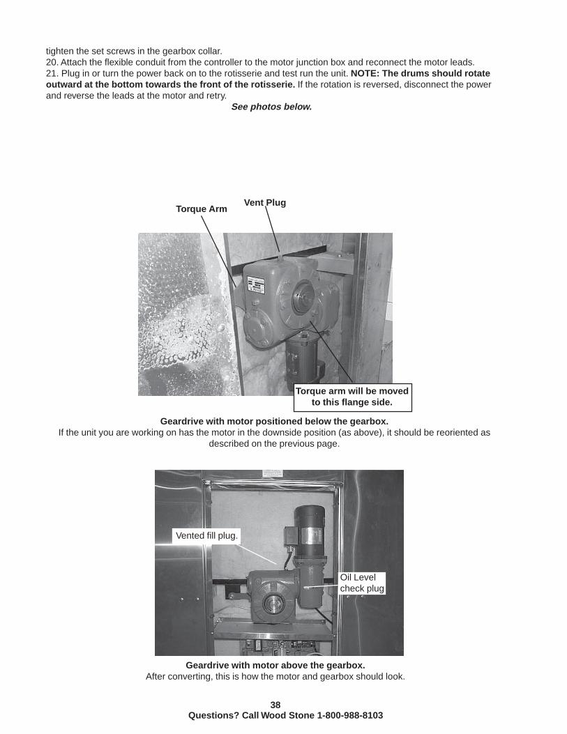
Geardrive with motor above the gearbox.After converting, this is how the motor and gearbox should look.
Oil Levelcheck plug
Vented fill plug.
Torque arm will be movedto this flange side.
tighten the set screws in the gearbox collar.20. Attach the flexible conduit from the controller to the motor junction box and reconnect the motor leads.21. Plug in or turn the power back on to the rotisserie and test run the unit. NOTE: The drums should rotateoutward at the bottom towards the front of the rotisserie. If the rotation is reversed, disconnect the powerand reverse the leads at the motor and retry.
See photos below.

39Questions? Call Wood Stone 1-800-988-8103
Drum Realignment Procedure
1.Cut two lengths of 2x4 lumber to 20” each.2. Working from the back (door) side of the rotisserie, rotate the drums until one of the 2x4’s can be blocked between one of the left receptacles on the left drum and the floor of the rotisserie.3. Use a marker to make a line around the shaft where it enters the locking collar on the left side drum. Also measure and take note of the amount of collar protruding from the left side drum. Repeat this entire step for the right side drum. This will give you some refer - ence points in the unlikely event that one or both of the drums move laterally during the alignment procedure.
IMPORTANT!!DO NOT LOOSEN THE 2” COLLAR NUTS ON THE SHAFT!
4.Place the second 2x4 at the right side drum and rotate the drum, using the jog switch, until one of the receptacles rests against its top, as was done on the left drum. Make sure that the amount the collar protrudes from the shaft, and its relation to the mark on the shaft remain the same as before for each drum.5.Using a 2” wrench, tighten the right collar as tight as possible. You will find it helpful to use a handle extension on the wrench. Retighten the left side collar in the same manner making sure that the left drum does not rotate on the shaft. Remove the 2x4 blocks.6. Test fit the spits in all of the sockets to assure a proper fit. There should be 1/8” minimum to 1/4” maximum freeplay between the spit shoulder and the idle side receptacle.7. Start the rotisserie and check the rotation of the drums, making certain they do not drag on the cabinet walls.
Drum
Locking collar
Spit receptacle
20” 2x4 block
Cabinet Floor
Spit
Freeplay1/8”-1/4”
Spit receptacle and drum
Questions ? Call Wood Stone 1-800-988-8103

40Questions? Call Wood Stone 1-800-988-8103
Parts ListSFR and GFR Rotisserie Parts List

41Questions? Call Wood Stone 1-800-988-8103
Rulon Thrust Washer 50RO-0063 Rulon Bearing 50RO-0020 DC Speed controller - TYPE 1 RP-70RO-0003 DC Speed Controller - TYPE 2 70ROC-0001 DC Motor 70RO-0004 Motor Brush- Baldor RP-0001 Motor Brush - Leeson RP-0027 Motor Switch Breaker (used w/TYPE 1 controller) 70RO-0013 Overload Thermal Unit (for Motor Switch Breaker) 70RO-0009 Speed Control Potentiometer RP-70RO-0022 Door Switch 70RO-0017 Gearbox (Brother) 70RO-0016 Speed Adjustment Knob 70RO-0023 Relay (for TYPE 2 control only) 70ROC-0300 Start Switch - Lighted Green 70ROC-0102 Stop Switch - Lighted Red 70ROC-0100 Lamp for lighted switches RP-0014 On/Off/Jog Toggle switch (for TYPE 1 controller) RP-0005 Rubber Boot for Toggleswitch RP-0006
SFR Parts List Description Part Number
GFR Parts List Description Part Number Rulon Thrust Washer 50RO-0063 Rulon Bearing 50RO-0020 DC Speed Controller - TYPE 2 70ROC-0001 DC Motor 70RO-0004 Motor Brush- Baldor RP-0001 Motor Brush - Leeson RP-0027 Speed Control Potentiometer RP-70RO-0022 Door Switch, bump bar switch 70RO-0017 Gearbox (Brother) 70RO-0016 Speed Adjustment Knob 70RO-0023 Relay (for TYPE 2 control only) 70ROC-0300 Start Switch - Lighted Green 70ROC-0102 Stop Switch - Lighted Red 70ROC-0100 Burner Switch - Lighhted Amber 70ROC-0101 Lamp for lighted switches RP-0014 Ignition Module 70ROC-0005 Gas Valve (specify gas type) 70ROC-0004 Igniter 70ROC-0006 Igniter Cable 70ROC-0007 Water Valve 70ROC-0050 Infrared Burner Orifice Call Wood Stone Radiant Burner orifice Call Wood StoneThrottle (flame height) valve 70ROC-0051

42Questions? Call Wood Stone 1-800-988-8103
Specifications and WarrantyGFR and SFR SpecificationsWood Stone Limited Warranty

43Questions? Call Wood Stone 1-800-988-8103
GFR Gas SpecificationsThe GFR rotisserie is equipped with a 1 inch NPT-Female gas connection. Have licensed gas installer providethe hook-up and test all fittings and pipe connections for leaks. Use approved gas leak detectors (soapsolutions or equivelant) over and around the pipe fittings and pipe connections. DO NOT USE AFLAME TO TEST FOR LEAKS.Wood Stone Recommends that the appliance’s individual shutoff valve (supplied by others) be left easily accessible.Gas Code LimitationsThe installation of this appliance must conform with local codes, or in the absence of local codes, with theNational Fuel Gas Code, ANSI Z223.1, The Natural Gas Installation Code CAN/CGA-B149.1 or the PropaneInstallation Code, CAN/CGA-B149.2, as applicable including: The appliance and its individual shutoff valve(supplied by others) must be disconnected from the gas supplypiping system during any pressure testing of that system at test pressures in excess of ½ psi (3.45kPa). The appliance must be isolated from the gas supply piping system by closing its individual manual shutoffvalve(supplied by others) during any pressure testing of the gas supply piping system at test pressure, equal toor less than 1/2psi (3.45kPa).All shutoffs and connections to the rotisserie must have a minimum I.D. of 1”. For longer runs it may benecessary to use larger piping to supply the oven. Undersized piping and/or valves can negatively effectthe performance of the rotisserie.
SFR and GFR ElectricalA 120 VAC 15 Amp circuit is sufficient. The unit must be grounded. Do not remove the ground pin on the powercord plug.

44Questions? Call Wood Stone 1-800-988-8103
Wood Stone Limited WarrantyWood Stone warrants its equipment to the original purchaser against defects in material or
manufacture for a period of one year from the original date of purchase, subject to the followingexclusions and limitations.
EXCLUSIONSThe warranties provided by Wood Stone do not apply in the following instances:
1. In the event that the equipment is improperly installed. Proper installation is the responsibility of theinstaller; proper installation procedures are prescribed by the Wood Stone installation manual.
2. In the event the equipment is improperly maintained. Proper maintenance is the responsibility of the user;proper maintenance procedures are prescribed in the Wood Stone installation manual.
3. In the event that the failure or malfunction of the appliance or any part thereof is caused by abnormal useor is otherwise not attributable to defect in material or manufacture.
4. In the event that the appliance, by whatever cause, has been materially altered from the condition in whichit left the factory.
5. In the event that the rating plate has been removed, altered or obliterated.
6. On parts that would be normally worn or replaced under normal conditions.
7. Normal cracking due to expansion and contraction stress relief in either the dome or floor.
8. In the event that pressed log products of any type have been burned in the equipment.
If any oral statements have been made regarding this appliance, such statements do not constitutewarranties and are not part of the contract of sale. This Limited Warranty constitutes the complete, final andexclusive statement with regard to warranties.THIS LIMITED WARRANTY IS EXCLUSIVE AND IN LIEU OF ALL OTHERWARRANTIES WHETHER WRITTEN, ORAL OR IMPLIED, INCLUDING, BUT NOTLIMITED TO, ANY WARRANTY OF MERCHANTABILITY OR FITNESS FORPARTICULAR PURPOSE OR WARRANTY AGAINST LATENT DEFECTS.
LIMITATIONS OF LIABILITY:In the event of warranty claim or otherwise, the sole obligation of Wood Stone shall be the repair and/orreplacement, at the option of Wood Stone, of the appliance or component or part thereof. Such repair and/orreplacement shall be at the expense of Wood Stone with the exception of travel over 100 miles or two hours,overtime, and holiday charges which shall be at the expense of the purchaser. Any repair or replacementunder this warranty does not constitute an extension of the original warranty for any period of the appliance orfor any component or part thereof. Parts to be replaced under this warranty will be repaired or replaced atthe option of Wood Stone with new or functionally operative parts. The liability of Wood Stone on any claim ofany kind, including claims based on warranty, expressed or implied, contract, negligence, strict liability or anyother theories shall be solely and exclusively the repair or replacement of the product as stated herein, andsuch liability shall not include, and purchaser specifically renounces any rights to recover, special, incidental,consequential or other damages of any kind whatsoever, including, but not limited to, injuries to persons ordamage to property, loss of profits or anticipated profits, or loss of use of the product.
TO SECURE WARRANTY SERVICE:If you claim a defect covered by this Limited Warranty, direct your claim to:
Wood Stone Corporation, 1801 W. Bakerview Rd. Bellingham, WA 98226 USA Attn: National ServiceManager