wolfpac tm 175 welding generator - gases and welding equipment€¦ · air liquide wolfpactm 175...
TRANSCRIPT

WOLFPAC 175 Welding Generator
OWNER’S MANUAL
• Stick (SMAW)
• TIG (GTAW) Scratch Start • Auxiliary Power
Manual No. MI 207.19.00.00
TM
WOLFPAC 175 CC Welding Generator

3
WARNING Read and understand this entire Owner’s Manual and your employer’s safety practices before installing, operating, or servicing the equipment. While the information contained in this Owner’s Manual represents our best judgment, AIR LIQUIDE assumes no liability for its use. AIR LIQUIDE WOLFPACTM 175 Welding Generator Owner’s Manual Number MI 207.19.00.00 All rights reserved. Reproduction of this work, in whole or in part, without written permission of the publisher is prohibited. The publisher does not assume and hereby disclaims any liability to any part for any loss or damage caused by any error or omission in the AIR LIQUIDE WOLFPACTM 175 Welding Generator Owner’s Manual, whether such error results from negligence, accident, or any other cause. WOLFPACTM Trademark of Air Liquide Canada Inc.
Air Liquide Welding is a trademark of L’Air Liquide S.A.

4
TABLE OF CONTENTS
1. GENERAL INFORMATION......................................................................................................5
1.1 Notes, Cautions and Warnings ...........................................................................................5
1.2 Important Safety Precautions .............................................................................................5
1.3 Publications ..........................................................................................................................8
2. TECHNICAL SPECIFICATIONS...............................................................................................9
3. FRONT PANEL DESCRIPTION..............................................................................................10
4. OVERALL DIMENSIONS AND WEIGHT.............................................................................12
5. SPECIFICATIONS.....................................................................................................................13
5.1 Description.........................................................................................................................13
6. SETTING-UP THE WELDING GENERATOR......................................................................14
7. WARNING..................................................................................................................................15
8. SIMULTANEOUS WELDING AND POWER AVAILABITLITY.........................................16
9. WIRING OPTIONAL 230 VOLT PLUG..................................................................................17
10. GROUNDING THE GENERATOR TO A TRUCK OR A TRAILER FRAME...................18
11. GROUNDING THE GENERATOR WHEN CONNECTING TO HOME, SHOP,
OR FARM WIRING..................................................................................................................18
12. TYPICAL PROCESS CONNECTIONS....................................................................................19
13. SELECTING MINIMUM WELD CABLE SIZES...................................................................19
14. WELD OUTPUT CONNECTION .............................................................................................20
15. SEQUENCE OF OPERATION..................................................................................................21
15.1 Starting...........................................................................................................................21
15.2 Stopping the Engine .......................................................................................................22
15.3 Shielded Metal Arc Welding (SMAW).........................................................................23
16. ROUTINE MAINTENANCE....................................................................................................24
17. PARTS LIST – EXPANDED VIEW..........................................................................................25
18. WIRING DIAGRAM.................................................................................................................29

5
1. GENERAL INFORMATION
1.1 Notes, Cautions and Warnings Throughout this manual, notes, cautions and warnings are used to highlight important information. These highlights are categorized as follows: NOTE An operation, procedure, or background information that requires additional emphasis or is helpful in efficient operation of the system.
CAUTION A procedure which, if not properly followed, may cause damage to the equipment.
WARNING A procedure which, if not properly followed, may cause injury to the operator or others in the operating area.
1.2 Important Safety Precautions
WARNING OPERATION AND MAINTENANCE OF WELDING EQUIPMENT CAN BE DANGEROUS AND HAZARDOUS TO YOUR HEALTH. To prevent possible injury, read, understand and follow all warnings, safety precautions and instructions before using the equipment. Call 1-800-817-7697 or your local distributor if you have any questions.
GASES AND FUMES
Gases and fumes produced during the arc welding/cutting process can be dangerous and hazardous to your health. • Keep all fumes and gases from the breathing area. Keep your head out of the welding fume plume.

6
• Use an air-supplied respirator if ventilation is not adequate to remove all fumes and gases.
• The kinds of fumes and gases from arc welding/cutting depend on the kind of coatings being used on the metal and the different processes. You must be very careful when cutting or welding any metals that may contain one or more of the following:
Antimony Arsenic Barium Beryllium Cadmium Chromium Cobalt Copper Lead Manganese Mercury Nickel Selenium Silver • Always read the Material Safety Data Sheet (MSDS) that should be supplied with the material you are
using. These MSDSs will give you the information regarding the kind and amount of fumes and gases that may be dangerous to your health.
• For information on how to test for fumes and gases in your workplace, refer to item 1 in Subsection 1.3 (Publication) in this manual.
• Use special equipment, such as water or down-draft welding or cutting tables, to capture fumes and gases.
• Do not use the welding torch in an area where combustible or explosive gases or materials are located.
• Phosgene, a toxic gas, is generated from the vapors of chlorinated solvents and cleansers. Remove all
sources of these vapors.
ELECTRIC SHOCK
Electric shock can injure or kill. The arc welding process uses and produces high-voltage electrical energy. This electrical energy can cause severe or fatal shock to the operator or other employees in the workplace.
• Never touch any parts that are electrically “live” or “hot”.
• Wear dry gloves and clothing. Insulate yourself from the workpiece or other parts of the welding circuit.
• Repair or replace all worn or damaged parts.
• Extra care must be taken when the workplace is moist or damp.
• Install and maintain equipment according to the National Electrical Code; refer to item 9 in Subsection 1.3 (Publications).
• Disconnect power source before performing any service or repairs.
• Read and follow all the instructions in the owner’s manual.

7
FIRE AND EXPLOSION
Fire and explosion can be caused by hot slag, sparks or the arc weld.
• Be sure there is no combustible or flammable material in the workplace. Any material that cannot be removed must be protected.
• Ventilate all flammable or explosive vapors from the workplace.
• Do not cut or weld on containers that may have held combustibles.
• Provide a fire watch when working in an area where fire hazards may exist.
• Hydrogen gas may be formed and trapped under aluminum workpieces when they are cut under water or while using a water table. DO NOT cut aluminum alloys under water or on a water table unless the hydrogen gas can be eliminated or dissipated. Trapped hydrogen gas that is ignited will cause an explosion.
NOISE
Noise can cause permanent hearing loss. Arc welding or cutting processes can cause noise levels that exceed safe limits. You must protect your ears from these high, loud noise levels to prevent permanent loss of hearing.
• To protect your hearing from high noise levels, wear protective earplugs and/or earmuffs. Protect others in the workplace.
• Noise levels should be measured to be sure the decibels (sound) do not exceed safe levels.
• For information on how to test for noise, see item 1 in Subsection 1.3 (Publications).
ARC WELDING RAYS Arc welding or cutting rays can injure your eyes and burn your skin. The arc welding cutting process produces very bright ultraviolet and infrared light. These arc rays will damage your eyes and burn your skin if you are not properly protected. • To protect your eyes, always wear a welding helmet or shield. Also, always wear safety glasses with side
shields, goggles or other protective eyewear. Keep helmet and safety glasses in good condition. Replace lenses when cracked, chipped or dirty.
• Wear welding gloves and suitable clothing to protect your skin from the arc rays and sparks.
• Protect others in the work area from the arc rays. Use protective booths, screens or shields.
• Use the shade of lens as recommended in item 4, Subsection 1.3 (Publications).

8
1.3 Publications Refer to the following standards or their latest revisions for more information: 1. OSHA, SAFETY AND HEALTH STANDARDS, 29CFR 1910, obtainable from the Superintendent of
Documents, U.S. Government Printing Office, Washington, D.C. 20402. 2. ANSI Standard Z49.1, SAFETY IN WELDING AND CUTTING, obtainable from the American Welding
Society, 550 N.W. LeJeune Road, Miami, FL 33126. 3. NIOSH, SAFETY AND HEALTH IN ARC WELDING AND GAS WELDING AND CUTTING, obtainable from
the Superintendent of Documents, U.S. Government Printing Office, Washington, D.C. 20402. 4. ANSI Standard Z87.1, SAFE PRACTICES FOR OCCUPATION AND EDUCATIONAL EYE AND FACE
PROTECTION, obtainable from the American National Standards Institute, 1430 Broadway, New York, NY 10018.
5. ANSI Standard Z41.1, STANDARD FOR MEN’S SAFETY-TOE FOOTWEAR, obtainable from the American
National Standards Institute, 1430 Broadway, New York, NY 10018. 6. ANSI Standard Z49.2, FIRE PREVENTION IN THE USE OF CUTTING AND WELDING PROCESSES,
obtainable from the American National Standards Institute, 1430 Broadway, New York, NY 10018. 7. AWS Standard A6.0, WELDING AND CUTTING CONTAINERS WHICH HAVE HELD COMBUSTIBLES,
obtainable from the American Welding Society, 550 N.W. Lejeune Road, Miami, FL 33126. 8. NFPA Standard 51, OXYGEN-FUEL GAS SYSTEMS FOR WELDING, CUTTING AND ALLIED PROCESSES,
obtainable from the National Fire Protection Association, Batterymarch Park, Quincy, MA 02269. 9. NFPA Standard 70, NATIONAL ELECTRICAL CODE; obtainable from the National Fire Protection
Association, Batterymarch Park, Quincy, MA 02269 10. NFPA Standard 51B, CUTTING AND WELDING PROCESSES, obtainable from the National Fire Protection
Association, Batterymarch Park, Quincy, MA 02269. 11. CGA Pamphlet P-1, SAFE HANDLING OF COMPRESSED GASES IN CYLINDERS, obtainable from the
Compressed Gas Association, 1235 Jefferson Davis Highway, Suite 501 Arlington, VA 22202. 12. CSA Standard W117.2, CODE FOR SAFETY IN WELDING AND CUTTING, obtainable from the Canadian
Standards Association, Standards Sales, 178 Rexdale Boulevard, Rexdale, Ontario, Canada M9W 1R3. 13. NWSA booklet, WELDING SAFETY BIBLIOGRAPHY, obtainable from the National Welding Supply
Association, 1900 Arch Street, Philadelphia PA 19103. 14. American Welding Society Standard AWSF4.1, RECOMMENDED SAFE PRACTICES FOR THE
PREPARATION FOR WELDING AND CUTTING OF CONTAINERS AND PIPING THAT HAVE HELD HAZARDOUS SUBSTANCES, obtainable from the American Welding Society, 550 N.W. LeJeune Rd., Miami, FL 33126.
15. ANSI Standard Z88.2, PRACTICES FOR RESPIRATORY PROTECTION, obtainable from the American
National Standards Instiute, 1430 Broadway, New York, NY 10018.

9
2. TECHNICAL SPECIFICATIONS
WELDING GENERATOR DC DC amperage range 40 - 170 A with continuous control DC welding current 170 A at 60% duty cycle DC welding current 140 A at 100% duty cycle VOLTAGE DC 90 OCV AUXILIARY POWER 60 Hz Single-phase 115 V 2 kVA – 230 V 4 kVA ENGINE Make/Type HONDA Model series GX 270 Number of cylinders 1 Displacement 270 cc Power 9 HP Engine speed 3600 RPM Cooling system Air Starting system Manual recoil starter Oil capacity 1.1 l – 0.3 gal US Fuel capacity 6 l – 1.6 gal US Fuel consumption 2.9 l / h – 0.76 gal / h (gal US) DIMENSION AND WEIGHT Height 510 mm 20.07 in Width 490 mm 19.29 in Length 730 mm 28.74 in Weight 97 kg 214 lb
10
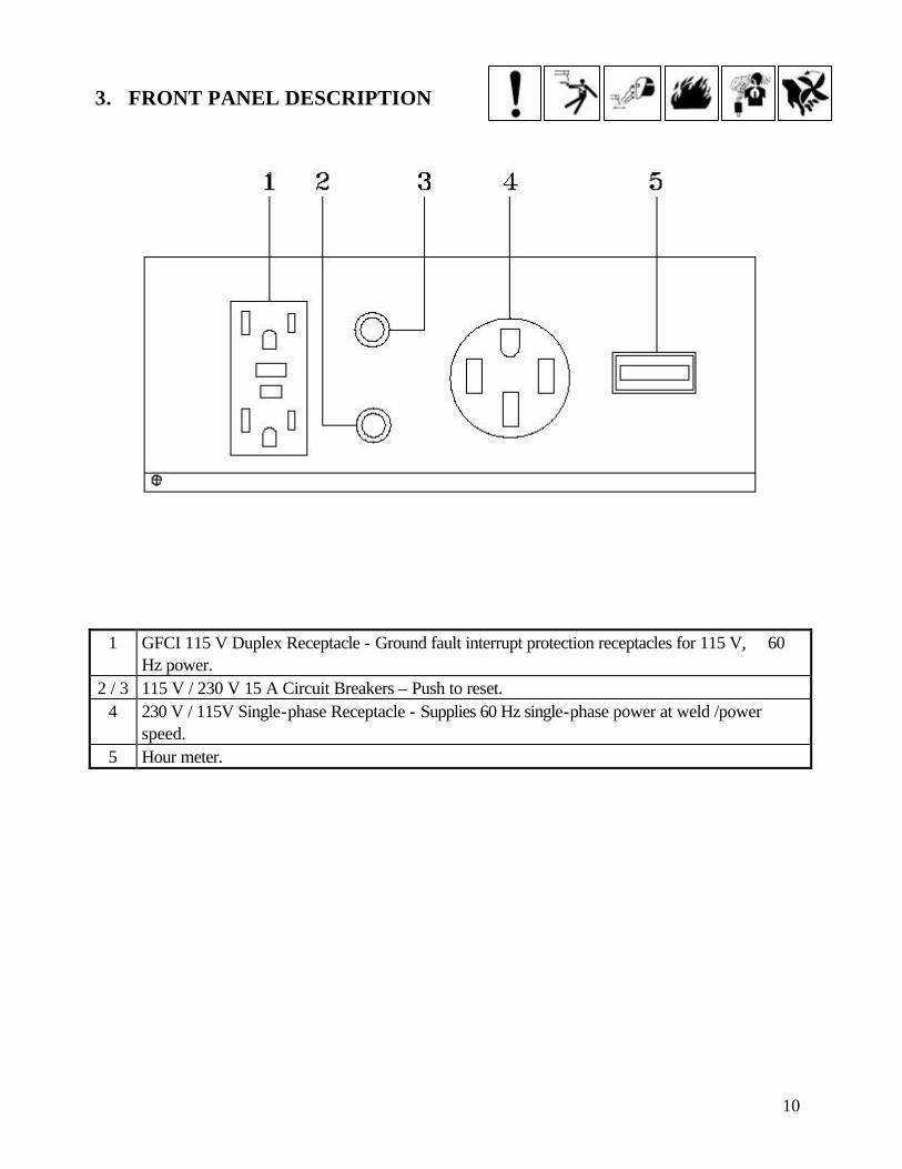
3. FRONT PANEL DESCRIPTION
1 GFCI 115 V Duplex Receptacle - Ground fault interrupt protection receptacles for 115 V, 60 Hz power.
2 / 3 115 V / 230 V 15 A Circuit Breakers – Push to reset. 4 230 V / 115V Single-phase Receptacle - Supplies 60 Hz single-phase power at weld /power
speed. 5 Hour meter.

11
FRONT PANEL DESCRIPTION
1 Earth ground connection. 2 Electrode negative connection 120 / 170 A. 3 Electrode negative connection 80 / 130 A. 4 Fine adjustment - Controls throttle for fine welding control of CC current. Rotating this control in a
clockwise direction increases the amperage or voltage output. The scale surrounding the control represents approximate actual amperage.
5 Electrode negative connection 40 / 90 A. 6 Electrode positive connection. 7 Serial number.
12
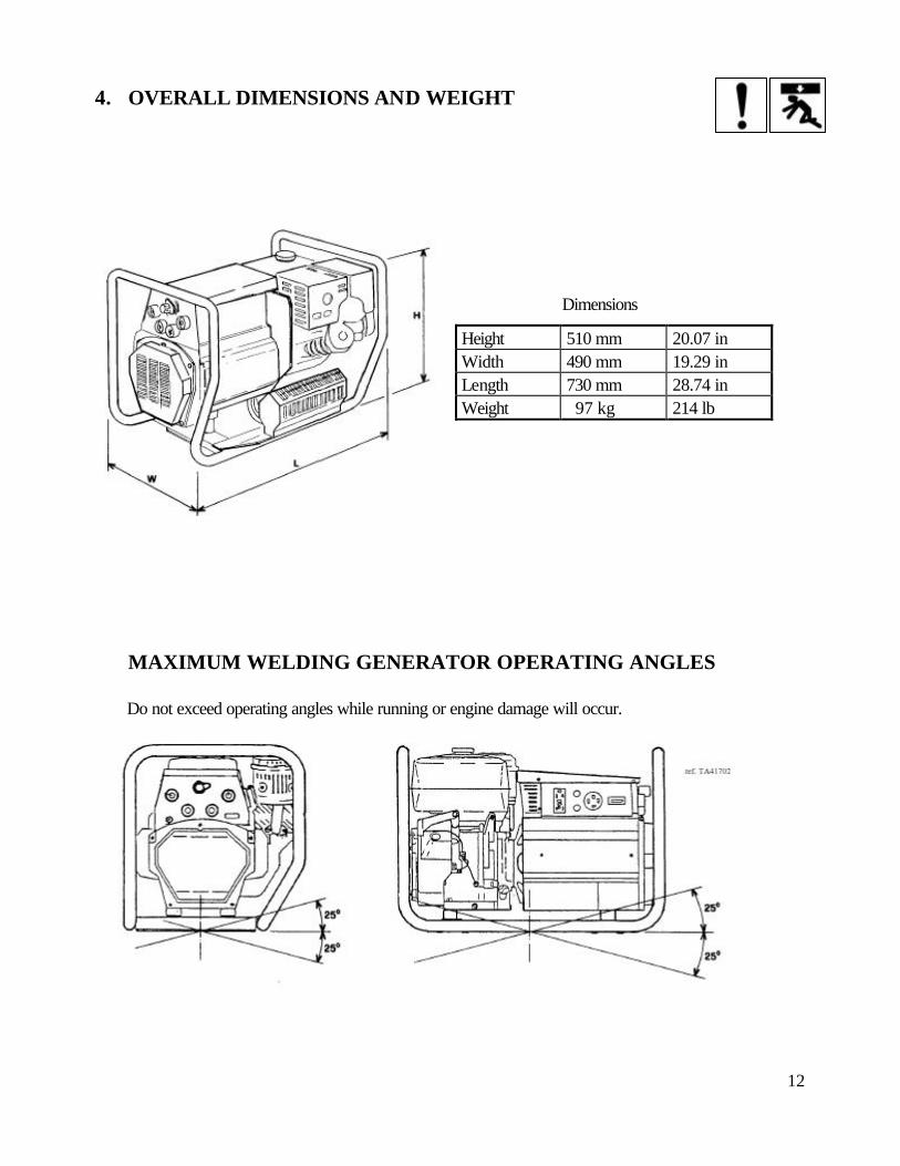
4. OVERALL DIMENSIONS AND WEIGHT
MAXIMUM WELDING GENERATOR OPERATING ANGLES
Do not exceed operating angles while running or engine damage will occur.
Dimensions
Height 510 mm 20.07 in Width 490 mm 19.29 in Length 730 mm 28.74 in Weight 97 kg 214 lb

13
5. SPECIFICATIONS
5.1 Description The AIR LIQUIDE WOLFPAC™ 175 is a gasoline-engine-driven DC welding generator. This unit is designed for use with the Shielded Metal Arc Welding (SMAW) and TIG (GTAW) Scratch Start processes. NOTE: Full output may not be achieved before engine break-in time. Engine break-in time is approximately 80 hours. DUTY CYCLE
The duty cycle of a welding generator is the percentage of a 10 (ten) minute period for which the welding generator can be operated at a given output without causing overheating and damaging of the unit. This unit is rated at 60% duty cycle when operated at 170 A. The unit can be operated at 170 A for 6 (six) consecutive minutes, but it must operate at no load for the remaining 4 (four) minutes to allow for proper cooling. If the welding amperes decrease, the duty cycle increases. If the welding amperes are increased beyond the rated output, the duty cycle will decrease. CAUTION EXCEEDING DUTY CYCLE RATINGS will cause the thermal overload protection circuit to become energized and shut down output until the unit cools to normal operating temperatures. CONTINUAL EXCEEDING OF DUTY CYCLE RATINGS can cause damage to the welding power source. • Do not exceed indicated duty cycles.

14
6. SETTING UP THE WELDING GENERATOR
1. Lifting forks 2. Trailer
Do not exceed trailer capabilities.
Movement
1
Location Airflow Clearance
2
Do not lift unit from end.
1

15
7. WARNING
ENGINE FUEL CAN CAUSE FIRE OR EXPLOSION
- Stop engine before fueling. - Do not fuel while smoking or near sparks or flame. - Do not overfill tank; clean up any spilled fuel.
REMOVE FUEL CAP SLOWLY. FUEL SPRAY MAY CAUSE INJURY. FUEL MAY BE UNDER PRESSURE.
Rotate fuel cap slowly and wait until hissing stops before removing cap. - Check all fluids daily. - Engine must be cold and on a level surface. - Add fresh fuel when starting engine the first time. - Wipe dipstick clean and check oil: if oil is not up to full mark, add oil.

16
8. SIMULTANEOUS WELDING AND POWER AVAILABITLITY
Fine Current Control Set at Maximum
Weld current DC Auxiliary power, single-phase 115 / 230 V
170 A @ 26.8 V 0.5 kVA 120 A @ 24.8 V 2 kVA 70 A @ 22.8 V 3.5 kVA 0 A @ 0 V 4 kVA

17
9. WIRING OPTIONAL 230 VOLT PLUG
The plug can be wired for a 230 V, 2-wire load or a 115 / 230 V, 3-wire load. White - Neutral terminal YYY - Load 1 terminal XXX - Load 2 terminal Green - Ground terminal

18
10. GROUNDING THE GENERATOR TO A TRUCK OR A TRAILER FRAME
1. Generator base 2. Metal vehicle frame 3. Equipment grounding terminal 4. Grounding cable Use #10 AWG or larger insulated copper wire.
11. GROUNDING THE GENERATOR WHEN CONNECTING
TO HOME, SHOP, OR FARM WIRING
1. Equipment grounding terminal 2. Grounding cable Use #10 AWG or larger insulated copper wire. 3. Water meter 4. Metal water pipe 5. Driven ground rod
Grounding methods
Electrically bond generator frame to vehicle frame by
metal-to-metal contact.
19
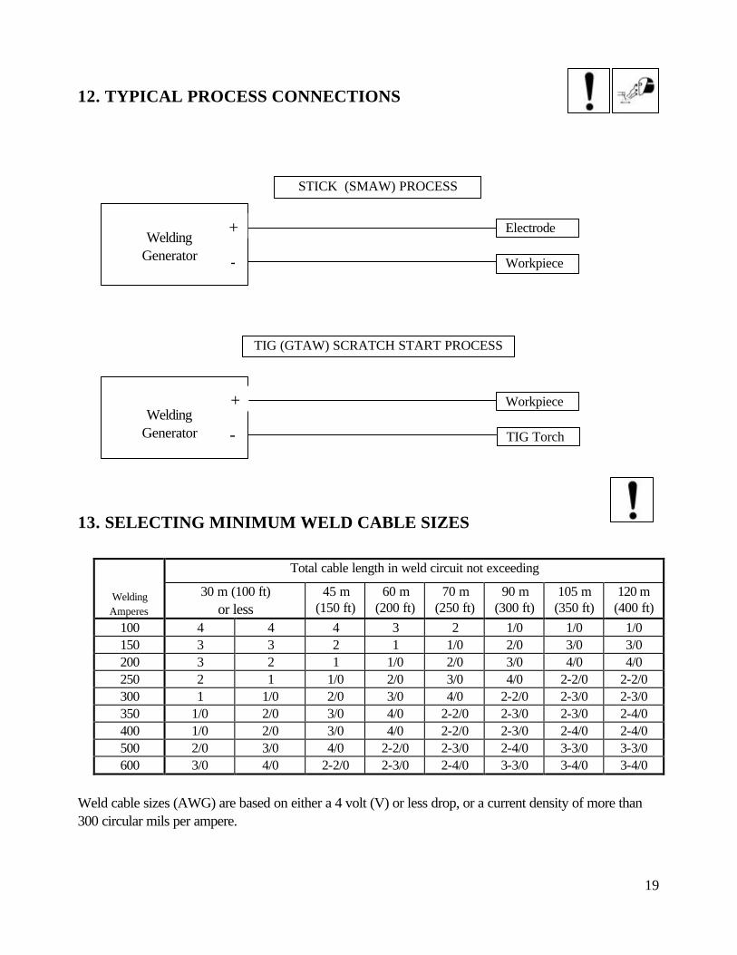
12. TYPICAL PROCESS CONNECTIONS
13. SELECTING MINIMUM WELD CABLE SIZES
Total cable length in weld circuit not exceeding
Welding Amperes
30 m (100 ft) or less
45 m (150 ft)
60 m (200 ft)
70 m (250 ft)
90 m (300 ft)
105 m (350 ft)
120 m (400 ft)
100 4 4 4 3 2 1/0 1/0 1/0 150 3 3 2 1 1/0 2/0 3/0 3/0 200 3 2 1 1/0 2/0 3/0 4/0 4/0 250 2 1 1/0 2/0 3/0 4/0 2-2/0 2-2/0 300 1 1/0 2/0 3/0 4/0 2-2/0 2-3/0 2-3/0 350 1/0 2/0 3/0 4/0 2-2/0 2-3/0 2-3/0 2-4/0 400 1/0 2/0 3/0 4/0 2-2/0 2-3/0 2-4/0 2-4/0 500 2/0 3/0 4/0 2-2/0 2-3/0 2-4/0 3-3/0 3-3/0 600 3/0 4/0 2-2/0 2-3/0 2-4/0 3-3/0 3-4/0 3-4/0
Weld cable sizes (AWG) are based on either a 4 volt (V) or less drop, or a current density of more than 300 circular mils per ampere.
Workpiece
Electrode
STICK (SMAW) PROCESS
Welding Generator
+
-
TIG Torch
Workpiece
TIG (GTAW) SCRATCH START PROCESS
Welding Generator
+
-

20
14. WELD OUTPUT CONNECTION
ELECTRIC SHOCK CAN KILL. ARCING CAN BURN SKIN OR DAMAGE ELECTRICAL CONNECTIONS CONNECTOR INSTALLATION 1. Obtain cable of desired length and proper size for installation. 2. If the installation requires a cable larger than 3/0 AWG, prepare one end of a 3/0 AWG pigtail no
longer than 0.61 m (2 ft) for connector installation. The remaining end of the pigtail is connected to the main run of a 3/0 AWG or larger weld cable.
3. Push weld cable through insulator. 4. Remove 20 mm (0.79 in) of insulation from end of cable. 5. Install supplied sleeve on stripped end of cable. 6. Insert cable with sleeve into connector body so that cable is snug and against bottom of connector
body. 7. Install and tighten set screw with supplied hex wrench to secure connector body onto cable. 8. Push insulator onto connector body to cover set screw.
WELD CABLE CONNECTIONS 1. Do not touch live electrical parts. 2. Shut down unit before making any weld output connections. 3. Do not change position of the welding cable connectors while welding. 4. Be sure that the connectors are secure in receptacle before welding.

21
15. SEQUENCE OF OPERATION
READ AND FOLLOW ALL SAFETY PRECAUTIONS BEFORE PROCEEDING WITH OPERATION.
15.1 Starting
1. Turn the fuel valve to the “ON” position. 2. Move the choke lever to the “CLOSE” position.
NOTE: Do not use the choke if the engine is warm or the air temperature is high. 3.Turn the throttle knob halfway around. 4. Start the engine.
- With recoil starter 5. Turn the engine switch to the “ON” position.

22
6. Pull the starter grip lightly until resistance is felt; then pull briskly.
CAUTION
DO NOT ALLOW THE STARTER GRIP TO SNAP BACK AGAINST THE ENGINE. RETURN IT GENTLY TO PREVENT DAMAGE TO THE STARTER.
7. As the engine warms up, gradually move the choke lever to the open position.
15.2 Stopping the Engine
To stop the engine in an emergency, turn the engine switch to the “OFF” position. Under normal condition use the following procedure: 1. Remove all electrical plugs. 2. Turn the engine speed control to its lowest setting. 3. Turn the engine switch to the“OFF” position.
23
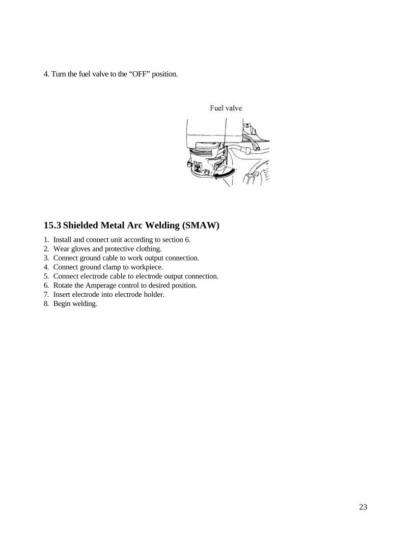
4. Turn the fuel valve to the “OFF” position.
15.3 Shielded Metal Arc Welding (SMAW)
1. Install and connect unit according to section 6. 2. Wear gloves and protective clothing. 3. Connect ground cable to work output connection. 4. Connect ground clamp to workpiece. 5. Connect electrode cable to electrode output connection. 6. Rotate the Amperage control to desired position. 7. Insert electrode into electrode holder. 8. Begin welding.

24
16. ROUTINE MAINTENANCE
ATTENTION: STOP ENGINE BEFORE MAINTENANCE
8 HOURS Ø Wipe up oil and fuel spills Ø Check fluid levels
50 HOURS Ø Change oil and oil filter Ø Clean cooling system
100 HOURS Ø Clean and tighten battery connections Ø Service the air cleaner
200 HOURS Ø Replace unreadable labels Ø Replace the fuel filter Ø Check valve clearance
250 HOURS Ø Check and clean spark arrestor
500 HOURS Ø Check spark plugs
1000 HOURS Ø Blow-out or vacuum inside as required

25
17. PARTS LIST – EXPANDED VIEW

26
SPARE PARTS LIST
27
Item No.
Replacement Part Number
Description Stock No.
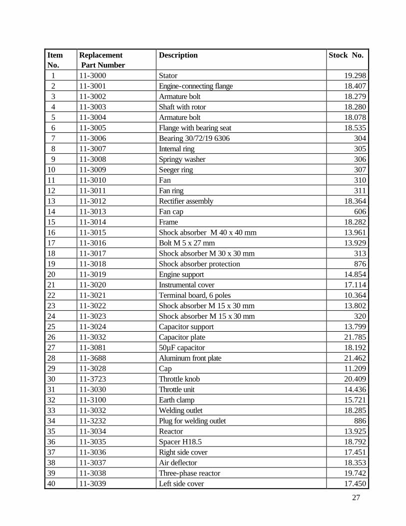
1 11-3000 Stator 19.298 2 11-3001 Engine-connecting flange 18.407 3 11-3002 Armature bolt 18.279 4 11-3003 Shaft with rotor 18.280 5 11-3004 Armature bolt 18.078 6 11-3005 Flange with bearing seat 18.535 7 11-3006 Bearing 30/72/19 6306 304 8 11-3007 Internal ring 305 9 11-3008 Springy washer 306 10 11-3009 Seeger ring 307 11 11-3010 Fan 310 12 11-3011 Fan ring 311 13 11-3012 Rectifier assembly 18.364 14 11-3013 Fan cap 606 15 11-3014 Frame 18.282 16 11-3015 Shock absorber M 40 x 40 mm 13.961 17 11-3016 Bolt M 5 x 27 mm 13.929 18 11-3017 Shock absorber M 30 x 30 mm 313 19 11-3018 Shock absorber protection 876 20 11-3019 Engine support 14.854 21 11-3020 Instrumental cover 17.114 22 11-3021 Terminal board, 6 poles 10.364 23 11-3022 Shock absorber M 15 x 30 mm 13.802 24 11-3023 Shock absorber M 15 x 30 mm 320 25 11-3024 Capacitor support 13.799 26 11-3032 Capacitor plate 21.785 27 11-3081 50µF capacitor 18.192 28 11-3688 Aluminum front plate 21.462 29 11-3028 Cap 11.209 30 11-3723 Throttle knob 20.409 31 11-3030 Throttle unit 14.436 32 11-3100 Earth clamp 15.721 33 11-3032 Welding outlet 18.285 34 11-3232 Plug for welding outlet 886 35 11-3034 Reactor 13.925 36 11-3035 Spacer H18.5 18.792 37 11-3036 Right side cover 17.451 38 11-3037 Air deflector 18.353 39 11-3038 Three-phase reactor 19.742 40 11-3039 Left side cover 17.450

28
SPARE PARTS LIST Item No.
Replacement Part Number
Description Stock No.
41 11-3040 Spring 14.139 42 11-3535 Front cover 20.700 43 11-3534 Closing plate 15.720 44 11-3043 Top cover 15.659 45 11-3044 Left protection grate 13.922 46 11-3151 Hour meter 19.657 47 11-3046 230 V, 50 A 14-50 single-phase outlet 19.655 48 11-3047 15 A circuit breaker 13.640 49 11-3048 Ring 14.270 50 11-3049 Circuit breaker cover 14.658 51 11-3050 115 V, 2 x 15 A GFCI 5-15R single-phase outlet 19.654 52 11-3051 Resistance cover 18.794 53 11-3052 Resistance support 18.793 54 11-3053 Resistance 14.432 55 11-3054 Resistance plate 18.795 56 11-3055 Resistance 17.117 57 11-3056 Resistance terminal 11.439 58 11-3057 Resistance support 12.830 59 11-3058 7 mm insulating washer 17.491 60 11-3059 22 mm female insulator 17.603 61 11-3060 12 mm insulating washer 17.490 62 11-3061 12 mm male insulator 17.602 63 11-3375 115 V, 2 x 15 A GFCI 5-15R single-phase cover 19.762 64 11-4001 Hook 23.415

29
18. WIRING DIAGRAM
TM