wobit.com.pl · 3 zimmer group committed to our customers we have succeeded for years by offering...
TRANSCRIPT

3
ZIMMER GROUPCOMMITTED TO OUR CUSTOMERS
WE HAVE SUCCEEDED FOR YEARS BY OFFERING OUR CUSTOMERS INNOVATIVE AND INDIVIDUALIZED SOLUTIONS. ZIMMER HAS GROWN CONTINUOUSLY AND TODAY WE HAVE REACHED A NEW MILESTONE: THE ESTABLISHMENT OF THE KNOW-HOW FACTORY. IS THERE A SECRET TO OUR SUCCESS?
Foundation. Excellent products and services have always been the founda-tion of our company’s growth. Zimmer is a source of ingenious solutions and important technical innovations. This is why customers with high expectations for technology frequently find their way to us. When things get tricky, Zimmer Group is in its best form.
Style. We have an interdisciplinary ap-proach to everything we do, resulting in refined process solutions in six areas of technology. This applies not just to devel-opment but to production as well. Zimmer Group serves all industries and stands ready to resolve even unique and highly individualized problems. Worldwide.
Motivation. Customer orientation is perhaps the most important factor of our success. We are a service provider in the complete sense of the word. Even our decision to identify ourselves as Zimmer Group reflects this reality. With Zimmer Group, our customers now have a single, centralized contact for all of their needs. We approach each customer’s situation with a high level of competence and a broad range of possible solutions.
www.zimmer-group.com

4
TECHNOLOGIES
HANDLING TECHNOLOGY
WITH MORE THAN 30 YEARS OF EXPERI-ENCE AND INDUSTRY KNOWLEDGE, OUR PNEUMATIC, HYDRAULIC AND ELECTRICAL HANDLING COMPONENTS AND SYSTEMS ARE GLOBAL LEADERS.
Components. More than 2000 stan-dardized gripper systems, positioning systems, robotools and much more. We offer a complete selection of technolo- gically superior products that are ready for rapid delivery.
Semistandard. Our modular approach to design enables custom configurations and high rates of innovation for process automation.
Systems. We are particularly strong in providing custom system solutions for handling technologies, robotics and vacuum engineering.
DAMPING TECHNOLOGY
INDUSTRIAL DAMPING TECHNOLOGY AND SOFT CLOSE PRODUCTS EXEMPLIFY THE INNOVATION AND PIONEERING SPIRIT OF THE KNOW-HOW FACTORY.
Industrial damping technology. Whether standard or customized solu-tions, our products stand for the highest cycle rates and maximum energy absorp-tion with minimal space requirements.
Soft Close. Development and mass production of pneumatic and fluid damp-ers with extraordinary quality and rapid delivery.
OEM und direct. Whether they need components, returning mechanisms or complete production lines – we are the trusted partner of many prestigious customers.
LINEAR TECHNOLOGY
WE DEVELOP LINEAR COMPONENTS AND SYSTEMS THAT ARE INDIVIDUALLY ADAPTED TO OUR CUSTOMERS’ NEEDS.
Clamping and braking elements. We offer more than 4000 types for profiled and rounded rails as well as for a variety of guide systems from all manufacturers. It makes no difference whether you prefer manual, automatic, electric or hydraulic drive.
Individualized systems. The unique functionality and precision of our clamping and braking elements open up numerous possibilities for custom applications such as active or semi- active braking and damping.
www.zimmer-group.com

5
PROCESS TECHNOLOGY
MAXIMUM EFFICIENCY IS ESSENTIAL FOR SYSTEMS AND COMPONENTS USED IN PROCESS TECHNOLOGY. HIGH-LEVEL CUS-TOM SOLUTIONS ARE OUR TRADEMARK.
A rich reservoir of experience. Our know-how ranges from the development of materials, processes and tools through product design to production of series products. Challenge us!
Deep production capabilities. The Zimmer Group pairs these capabilities with fl exibility, quality and precision, even when making custom products.
Series production. We manufacture demanding products out of metal (MIM), elastomers and plastics with fl exibility and speed.
TOOLING TECHNOLOGY
ZIMMER GROUP DEVELOPS INNOVATIVE METAL, WOOD AND COMPOSITE MATERIAL PROCESSING TOOL SYSTEMS FOR ALL INDUSTRIES. NUMEROUS CUSTOMERS CHOOSE US AS THEIR SYSTEMS AND INNO-VATION PARTNER.
Knowledge and experience. Industry knowledge and a decades-long devel-opment partnership for exchangeable assemblies, tool interfaces and tool sys-tems predestine us for new challenges around the world.
Components. We deliver numerous standard components from stock and develop innovative, customized systems for OEM and end users – far beyond just the metal and wood processing industries.
Variety. Whether you have machining centres, lathes, or fl exible production cells, the power tools, holders, assem-blies and drilling heads of Zimmer Group are ready for action.
MACHINE TOOLING TECHNOLOGY
AS A DRIVING FORCE IN OUR INDUSTRY, WE DELIVER HIGH-VALUE SOLUTIONS IN THE FIELD OF MECHANICAL ENGINEERING, FULLY ACCORDING TO THE NEEDS OF OUR CUSTOMERS.
Development partner. We accompany you from brainstorming to inspection of the fi nal machine, always according to your expectations.
Components. We deliver series products and modules, fi ve-axis heads, motor spin-dles, gearbox swivelling heads, add-on assemblies and motors.
Systems. The Know-how Factory stands for solutions in the fi elds of mechanical engineering systems, specialty solutions, custom assemblies and mechanical modules. We manufacture and confi gure multiple-spindle and large-angles as well as large boring heads.
www.zimmer-group.com

6
510 N 520 N 650 N
610 N
590 N
460 N
Gripper Series 5000
Length of the gripper fingers max.
Gripper series with Steel Linear Guide
BenchmarkT-slot guide
PRODUCT BENEFITS OF THE GRIPPER SERIES GPP5000 / GPD5000 / GEP5000 / GED5000
Is installing the most powerful components important to you?
► Increase the safety of your machine by installing a gripper from this series
► It offers you up to 30 % higher gripping force and up to 10 % higher static forces and moments
► Using it means you can install gripper fi ngers that are up to 10 % longer than the best-known models in the market
► And you can be sure that these grippers give you the same performance as electrically driven grippers
Do you want to use one gripper for any task?
► Cut the number of articles you manage
► And so reduce your design and stock-keeping costs to a minimum
► The gripper guarantees you process reliability, no mat-ter what the environmental conditions
► Corrosion protection included
► Select either a pneumatic or electrical drive, to give you maximum fl exibility when creating your design
Are details important to you?
► The transverse sensor grooves mean you can change the piston position sensing quickly and easily, wherev-er the gripper is installed
► Only one interference contour check required, be-cause a spacer compensates for the height difference between the electrical and pneumatic gripper
► With additional pin holes underneath the cover plate for customer-specifi c attachments
► With integrated lubrication reservoir
www.zimmer-group.com

7
Universal jaw aluminium Changeable jaw, loose-part-set
Changeable jaw, fi x-part 2-Position-Sensor Cable 0,3 m - Connector M8
Inductive Proximity Switch Cable 0,3 m - Connector M8
Plug-in connector Angled Ca-ble 5m - Socket M8 (female)
Angled Fittings - Quick Connect Style
Quick Exhaust Valve
Do you want state-of-the-art technology in your ma-chine?
► The gripper’s Steel Linear Guide combines proven linear guide principles with the very latest sealing and DLC technology
► You benefi t from one of the most robust and longlast-ing grippers currently available on the market, with a maintenance-free working life of up to 30 million cycles
Do you want a wide range of accessories, perfectly tailored to your gripper?
► Our product range has quick-release jaws that fi t every Series 5000 gripper, so you can reduce setup times to a minimum
► 2-position sensors that enables you to space saving position sensing
► Our multitude of tools and accessories means you get everything you need for your gripper from one source
www.zimmer-group.com

8
►
► P
T
►
C
O
---
► N
S
►
►
► P D
► P
►G
P1050PPG CN
mm
5000
Selection of Grippers
Option
Safety characteristics
Basis version
High force
Stroke per jaw
Product family
Design2- Jaw parallel grippers
Type of drivePneumatic
Product Grippers
For external gripping, self-lo-cking, spring closing
For internal gripping, self- locking, spring opening
No grip force retention at pressure loss
Temperature-resistant version up to 130°C
Protector version IP67 (purged air)
3 - Jaw concentric grippers
with criteria on design, type of drive and stroke
PRODUCT KEY GPP5000 / GPD5000
www.zimmer-group.com

1
2
3
4
9
SERIES GPP5000 / GPD5000 / GEP5000 / GED5000OVERVIEW OF INSTALLATION SIZES
2-JAW PARALLEL GRIPPER PNEUMATIC
SERIES GPP5000 10
Size GPP5003 12Size GPP5004 16Size GPP5006 20Size GPP5008 24Size GPP5010 28Size GPP5013 32Size GPP5016 36Size GPP5025 40Size GPP5030 44
3-JAW CONCENTRIC GRIPPER PNEUMATIC
SERIES GPD5000 48
Size GPD5003 50Size GPD5004 54Size GPD5006 58Size GPD5008 62Size GPD5010 66Size GPD5013 70Size GPD5016 74Size GPD5025 78Size GPD5030 82
2-JAW PARALLEL GRIPPER ELECTRIC
SERIES GEP5000 86
Size GEP5006 88Size GEP5008 92Size GEP5010 96
3-JAW CONCENTRIC GRIPPER ELECTRIC
SERIES GED5000 100
Size GED5006 102Size GED5008 106Size GED5010 110
Data, Drawings, 3-D Models, Operating Instructions ◄ www.zimmer-group.com

1
10
► Our products love the challenge!Extreme conditions, all over the world—our tried and tested components and systems give you limitless possibilities: Find the best product for your specifi c use: www.zimmer-group.com
HOW TO ORDER CORRECTLY
Order no. GPP5010
Basis version N
► The product order numbers are arranged according to this diagram:
High force S
For external gripping, self-locking, spring closing C
For internal gripping, self-locking, spring opening O
Protector version IP67 for use in adverse environments (with purged air) P
temperature-resistant version to 130 °C T
2-JAW PARALLEL GRIPPERSSERIES GPP5000
► PRODUCT ADVANTAGES
“The Universal One” ► Up to 30% more gripping force than the benchmark
► 10% more static forces and moments than the benchmark
► Gripper fi ngers up to 10% longer than the bench-mark
► Gripper fi ngers weight up to 15% higher than the benchmark
► Sealed guide IP64 / Protector version IP67 (with purged air)
► Protected against corrosion
► Up to 30 million cycles without maintenance
► THE BEST PRODUCT FOR YOUR APPLICATION
www.zimmer-group.com ► Data, Drawings, 3-D Models, Operating Instructions
Serie
s G
PP50
00 /
2-
Jaw
Par
alle
l Grip
pers
/
pneu
mat
ic /
G
rippe
rs

5
6
8 7
1 29
3
4
1
11
Gripping force: arithmetic sum of the individual forces occuring at the jaws
Closing/opening time: Time required for the gripper jaws to travel the entire stroke distance
Repeatability: at end stops after 50/100 consecutive cycles
Cycle: Path that the pistons travel for a complete opening and closing movement
Maintenance: recommended at 30 mil. cycles (please see the installation instructions, download from www.zimmer-group.com)
► BENEFITS IN DETAIL
1Positively driven wedge hook transmission - Supports to absorb high forces and moments - Synchronized gripper jaw movement
2Gripper jaw - DLC coated to protect against corrosion - Gripper fi ngers mounted using removable centring sleeves - Lubricated for life via incorporated lubrication slots
3Steel Linear Guide - Steel in steel guide - Enables use of extremely long gripper fi ngers
4Mounting block - mounting for inductive proximity switch
5Integrated gripping force safety device - Spring built into cylinder chamber as an energy store
6Drive - Double-acting pneumatic rotor cylinder
7Mounting and positioning - Alternatively, on several sides for customized mounting - Pneumatic and electrical versions identical apart from height
8Sensing slot - mounting and positioning of magnetic fi eld sensors
9Dual lip seal - IP64 and up to IP67 (with purged air) for Protector version - Prevents grease from being squeezed out, increasing service life
► TERMS
Data, Drawings, 3-D Models, Operating Instructions ◄ www.zimmer-group.com
Serie
s G
PP50
00 /
2-
Jaw
Par
alle
l Grip
pers
/
pneu
mat
ic /
G
rippe
rs

1
12
► PRODUCT SPECIFICATIONS
► Gripping force diagram ► Forces and moments
[N]
[mm]NNC / NO
N
100
200
0
50
150
250
0302010 40 50 60
Gripping force as a function finger length. Displays static forces and moments that can also have an effect, besides the gripping force.
MxMy
Mr
Fa
Mr [Nm] 7Mx [Nm] 14My [Nm] 13Fa [N] 550
Order no. GPP5003N GPP5003NC GPP5003NOStroke per jaw [mm] 2.5 2.5 2.5Gripping force in closing [N] 140 195 Gripping force in opening [N] 150 205Gripping force secured by spring min. [N] 55 55Closing time [s] 0.01 0.01 0.025Opening time [s] 0.01 0.025 0.01Weight per jaw max. [kg] 0.12 0.12 0.12Length of the gripper fi ngers max. [mm] 65 60 60Repetition accuracy +/- [mm] 0.01 0.01 0.01Operating pressure min. [bar] 3 4 4Operating pressure max. [bar] 8 7 7Operating temperature [°C] -10 ... +90 -10 ... +90 -10 ... +90Air volume per cycle [cm³] 2.1 4.8 4.8Protection to IEC 60529 IP64 IP64 IP64Weight [kg] 0.08 0.1 0.1
► Technical Data*
Order no. GPP5003NP GPP5003NCP GPP5003NOPProtection to IEC 60529 IP67** IP67** IP67**Weight [kg] 0.1 0.12 0.12
► Technical Data - Protector Version
Order no. GPP5003NT GPP5003NCT GPP5003NOTOperating temperature [°C] -10 ... +130 -10 ... +130 -10 ... +130
*All data measured at 6 bar** with purged air
► Technical Data - High Temperature Version
2-JAW PARALLEL GRIPPERSINSTALLATION SIZE GPP5003
► TECHNICAL DATA
Inst
alla
tion
size
GPP
5003
/
2-Ja
w P
aral
lel G
rippe
rs /
pn
eum
atic
/
Grip
pers
www.zimmer-group.com ► Data, Drawings, 3-D Models, Operating Instructions

32±0.02 ø5H7
18
±0.
02 ø
5H7
7
10.8
16
17
24
50
21.5
8
32
38
1820
33.7
1.2
15
21.58±0.02
19 14.5
14.5
22x 5 h7
8
32±0.02
20±0
.02
21.5
6.8
20
22
10.5
23
2x 1.5H7
4xM2 4x M2.5x4
4x 4h7
22
2.517
22
17
M3
2x M36
19
A B
2
4x M2.5DIN912*
2x M2.5DIN912*
1
1
Y
B` A`
2x M3
M3 2x 5H7x2191
2
X
A` B`
4xM3x6
2x 5H7x22x M2
1
12
X35
35
3
3
Y
12.5
911
24.7
81.
2
A B60
5 14.5
24.5
8
11.5 19
14.5
15.7
4x 4h722
19.7
3938
M 2
/ M
3
0.7 / 0.8
Ø 2
/ Ø
3
Ø 4
/ Ø
5
O-RingØ2x1 / Ø3x1
2
1
13
NC / NO
N
Protector version
Hoseless air feed-through
► TECHNICAL DRAWINGS
1 Gripper attachment
2 Energy supply
3 Fixing for gripper finger
6 Integrated slot for magnetic field sensor
bu Air purge connection option
dq Attachment option for customer-specific fittings
dt Adapter
du Gripper
A Air connection (close)
B Air connection (open)
K Air connection, alternative (close)
L Air connection, alternative (open)
Inst
alla
tion
size
GPP
5003
/
2-Ja
w P
aral
lel G
rippe
rs /
pn
eum
atic
/
Grip
pers
Data, Drawings, 3-D Models, Operating Instructions ◄ www.zimmer-group.com

1
2
3
5
4
1
14
► INCLUDED IN DELIVERY
Centering Disc Centering Disc
DST06510 015761
1 2
2-JAW PARALLEL GRIPPERSINSTALLATION SIZE GPP5003
Inst
alla
tion
size
GPP
5003
/
2-Ja
w P
aral
lel G
rippe
rs /
pn
eum
atic
/
Grip
pers
www.zimmer-group.com ► Data, Drawings, 3-D Models, Operating Instructions

A
A
23
4
30°
48
45
5
2.7 4 H
7
210
4
A-A
1
15
► RECOMMENDED ACCESSORIES
Universal jaw aluminium Universal jaw steel Rubber Coated Tape Smooth
Rubber Coated Tape Knobbed
Magnetic fi eld sensor Angled Cable 0,3 m - Connector M8
UB5003AL UB5003ST KF50G KF50N MFS103SKHC
Magnetic fi eld sensor Straight Cable 0,3 m - Connector M8
2-Position-Sensor Cable 0,3 m - Connector M8
Plug-in connector Angled Ca-ble 5m - Socket M8 (female)
Plug-in connector Straight Ca-ble 5m - Socket M8 (female)
Plug-in connector customiz-able Straight - Connector M8
MFS204SKHC MFSP2SKHC-01 KAW500 KAG500 S8-G-3
Plug-in connector customiz-able Straight - Connector M12
Angled Fittings - Barb Style Connection
Straight Fittings - Barb Style Connection
Quick Exhaust Valve Pressure Safety Valve
S12-G-3 WVM3 GVM3 DEV04 DSV1-8
3 3 4
4 4
5 5
One universal jaw is required for each gripper jaw 3
► TECHNICAL DRAWINGS ACCESSORIES
Inst
alla
tion
size
GPP
5003
/
2-Ja
w P
aral
lel G
rippe
rs /
pn
eum
atic
/
Grip
pers
Data, Drawings, 3-D Models, Operating Instructions ◄ www.zimmer-group.com

1
16
► PRODUCT SPECIFICATIONS
► Gripping force diagram ► Forces and moments
[mm]
250
500
0
125
375
625
0
NNC / NO
SSC / SO
NS
2010 30 40 50 60 70 80
[N]Gripping force as a function finger length. Displays static forces and moments that can
also have an effect, besides the gripping force.
MxMy
Mr
Fa
Mr [Nm] 14Mx [Nm] 29My [Nm] 23Fa [N] 750
Order no. GPP5004N GPP5004NC GPP5004NO GPP5004S GPP5004SC GPP5004SOStroke per jaw [mm] 4 4 4 2 2 2Gripping force in closing [N] 200 280 440 600 Gripping force in opening [N] 215 295 470 630Gripping force secured by spring min. [N] 80 80 160 160Closing time [s] 0.015 0.015 0.025 0.015 0.015 0.025Opening time [s] 0.015 0.025 0.015 0.015 0.025 0.015Weight per jaw max. [kg] 0.2 0.2 0.2 0.2 0.2 0.2Length of the gripper fi ngers max. [mm] 80 75 75 75 70 70Repetition accuracy +/- [mm] 0.01 0.01 0.01 0.01 0.01 0.01Operating pressure min. [bar] 3 4 4 3 4 4Operating pressure max. [bar] 8 7 7 8 7 7Operating temperature [°C] -10 ... +90 -10 ... +90 -10 ... +90 -10 ... +90 -10 ... +90 -10 ... +90Air volume per cycle [cm³] 5 12 12 5 12 12Protection to IEC 60529 IP64 IP64 IP64 IP64 IP64 IP64Weight [kg] 0.16 0.21 0.21 0.16 0.21 0.21
► Technical Data*
Order no. GPP5004NP GPP5004NCP GPP5004NOP GPP5004SP GPP5004SCP GPP5004SOPProtection to IEC 60529 IP67** IP67** IP67** IP67** IP67** IP67**Weight [kg] 0.25 0.3 0.3 0.25 0.3 0.3
► Technical Data - Protector Version
Order no. GPP5004NT GPP5004NCT GPP5004NOT GPP5004ST GPP5004SCT GPP5004SOTOperating temperature [°C] -10 ... +130 -10 ... +130 -10 ... +130 -10 ... +130 -10 ... +130 -10 ... +130
*All data measured at 6 bar** with purged air
► Technical Data - High Temperature Version
2-JAW PARALLEL GRIPPERSINSTALLATION SIZE GPP5004
► TECHNICAL DATA
Inst
alla
tion
size
GPP
5004
/
2-Ja
w P
aral
lel G
rippe
rs /
pn
eum
atic
/
Grip
pers
www.zimmer-group.com ► Data, Drawings, 3-D Models, Operating Instructions

S 221
35±0.02 ø6h7
22.6
8.7 22
±
0.02
ø6h
7
8.5
13
18.5
21.5
30
2926 32.0
5
30.5
47
1.2
24
35
42
65
8
2x 6h7
2.5
1924
18
12±0.02 25.5 N27.5 S
19 N 4
13
4
4xM22x 2H7
2.5
4x 5h7
4x M3x5.5
22
35±0.02
8
2632
30.5
±0.0
2
24
A B
M3
2x M5 26
19 Y
B` A`
2x M5
2x 6H7x2.5M3
2
1
194x M3
DIN912*
2x M3DIN912*
1
1
A` B`
4x M4x10
2x 6H7x2.5 2x M3
1
1 2
XY
3
3X
3535
101.
2
31
14.5
13 16A B
16.8
17.8
21.8 2
4x 5h72
78
23
324.3
248.5
14.5
3938
M 5
/ M
3
1.1 / 0.8
Ø 5
/ Ø
3
Ø 8
/ Ø
5
O-RingØ5x1.5 / Ø3x1
2
1
17
NC / NO / SC / SO
N / S
Protector version
Hoseless air feed-through
► TECHNICAL DRAWINGS
1 Gripper attachment
2 Energy supply
3 Fixing for gripper finger
6 Integrated slot for magnetic field sensor
bu Air purge connection option
dq Attachment option for customer-specific fittings
dt Adapter
du Gripper
A Air connection (close)
B Air connection (open)
K Air connection, alternative (close)
L Air connection, alternative (open)
Inst
alla
tion
size
GPP
5004
/
2-Ja
w P
aral
lel G
rippe
rs /
pn
eum
atic
/
Grip
pers
Data, Drawings, 3-D Models, Operating Instructions ◄ www.zimmer-group.com

1
2
3
7
6
4
5
1
18
► INCLUDED IN DELIVERY
Centering Disc Centering Disc
015761 024230
1 2
2-JAW PARALLEL GRIPPERSINSTALLATION SIZE GPP5004
Inst
alla
tion
size
GPP
5004
/
2-Ja
w P
aral
lel G
rippe
rs /
pn
eum
atic
/
Grip
pers
www.zimmer-group.com ► Data, Drawings, 3-D Models, Operating Instructions

A
A
30
6.5
30°
512
50
6
3.4 5 H
7
215
4.5
A-A
17 2
11
12
2x
5h7
2x M
3x9.
5
28
6 12
5.5
16.5
T8
1
19
► RECOMMENDED ACCESSORIES
Universal jaw aluminium Universal jaw steel Changeable jaw, loose-part-set
Changeable jaw, fi x-part Magnetic fi eld sensor Angled Cable 0,3 m - Connector M8
UB5004AL UB5004ST WB5004L WB5004F MFS103SKHC
Magnetic fi eld sensor Straight Cable 0,3 m - Connector M8
2-Position-Sensor Cable 0,3 m - Connector M8
Plug-in connector Angled Ca-ble 5m - Socket M8 (female)
Plug-in connector Straight Ca-ble 5m - Socket M8 (female)
Plug-in connector customiz-able Straight - Connector M8
MFS204SKHC MFSP2SKHC-01 KAW500 KAG500 S8-G-3
Plug-in connector customiz-able Straight - Connector M12
Angled Fittings - Quick Connect Style
Straight Fittings - Quick Connect Style
Quick Exhaust Valve Pressure Safety Valve
S12-G-3 WVM5 GVM5 DEV04 DSV1-8
3 3 4 5 6
6 6
7 7
One universal jaw is required for each gripper jaw 3 For each gripper jaw, one interchangeable jaw loose part set 4and one interchangeable jaw fi xed part 5are needed
► TECHNICAL DRAWINGS ACCESSORIES
Inst
alla
tion
size
GPP
5004
/
2-Ja
w P
aral
lel G
rippe
rs /
pn
eum
atic
/
Grip
pers
Data, Drawings, 3-D Models, Operating Instructions ◄ www.zimmer-group.com

1
20
► PRODUCT SPECIFICATIONS
► Gripping force diagram ► Forces and moments
400
800
0
200
600
1000
0
[N]
302010 40 50 60 70 80 90 100[mm]N
NC / NOSSC / SO
NS
Gripping force as a function finger length. Displays static forces and moments that can also have an effect, besides the gripping force.
MxMy
Mr
Fa
Mr [Nm] 43Mx [Nm] 70My [Nm] 46Fa [N] 1250
Order no. GPP5006N GPP5006NC GPP5006NO GPP5006S GPP5006SC GPP5006SOStroke per jaw [mm] 6 6 6 3 3 3Gripping force in closing [N] 330 455 740 1020 Gripping force in opening [N] 360 485 800 1080Gripping force secured by spring min. [N] 125 125 280 280Closing time [s] 0.025 0.015 0.035 0.025 0.015 0.035Opening time [s] 0.025 0.035 0.015 0.025 0.035 0.015Weight per jaw max. [kg] 0.4 0.4 0.4 0.4 0.4 0.4Length of the gripper fi ngers max. [mm] 100 90 90 90 85 85Repetition accuracy +/- [mm] 0.01 0.01 0.01 0.01 0.01 0.01Operating pressure min. [bar] 3 4 4 3 4 4Operating pressure max. [bar] 8 7 7 8 7 7Operating temperature [°C] -10 ... +90 -10 ... +90 -10 ... +90 -10 ... +90 -10 ... +90 -10 ... +90Air volume per cycle [cm³] 11 24 24 11 24 24Protection to IEC 60529 IP64 IP64 IP64 IP64 IP64 IP64Weight [kg] 0.28 0.35 0.35 0.28 0.35 0.35
► Technical Data*
Order no. GPP5006NP GPP5006NCP GPP5006NOP GPP5006SP GPP5006SCP GPP5006SOPProtection to IEC 60529 IP67** IP67** IP67** IP67** IP67** IP67**Weight [kg] 0.37 0.44 0.44 0.37 0.44 0.44
► Technical Data - Protector Version
Order no. GPP5006NT GPP5006NCT GPP5006NOT GPP5006ST GPP5006SCT GPP5006SOTOperating temperature [°C] -10 ... +130 -10 ... +130 -10 ... +130 -10 ... +130 -10 ... +130 -10 ... +130
*All data measured at 6 bar** with purged air
► Technical Data - High Temperature Version
2-JAW PARALLEL GRIPPERSINSTALLATION SIZE GPP5006
► TECHNICAL DATA
Inst
alla
tion
size
GPP
5006
/
2-Ja
w P
aral
lel G
rippe
rs /
pn
eum
atic
/
Grip
pers
www.zimmer-group.com ► Data, Drawings, 3-D Models, Operating Instructions

S 324.5
52
9
32 36.5
2835.5
57
1.5
31
42
42±0.02 ø8h7
55
27
10 2
70.
02 ø
8h7
11
17.5
26.5
36
4x 6h7
4x M4x62.
52.
5
13±0.02
21.5
76
31
2836.5
35.5
±0.0
2
42±0.02
9
28.4
N 6
2x 8h72.
5
24
2228
20
2x 2.5H7
4xM2.5
2.5
4.5
14
2x M5
M5
2
19
6
A B
Y
44
45
4x M4DIN912*
2x M4DIN912*
1
1
2xM3
4x M5x10
2x 8H7x2.5 2
1
1
7
A` B`
X Y3
3
M5
2x M5
2x 8H7x2.5
A`B`
191
2
X35
35
1417.5
39
1.5
10 18.5A B
23.52.
52.
51116
.5 28
92
23
38.46
4x 6h7
30.5
25
3938
M 5
/ M
3
1.1 / 0.8
Ø 5
/ Ø
3
Ø 8
/ Ø
5
O-RingØ5x1.5 / Ø3x1
2
1
21
NC / NO / SC / SO
N / S
Protector version
Hoseless air feed-through
► TECHNICAL DRAWINGS
1 Gripper attachment
2 Energy supply
3 Fixing for gripper finger
6 Integrated slot for magnetic field sensor
7 Mounting block
bu Air purge connection option
dq Attachment option for customer-specific fittings
dt Adapter
du Gripper
ep Clamp for sensor
eq Switch cam adjustment
A Air connection (close)
B Air connection (open)
K Air connection, alternative (close)
L Air connection, alternative (open)
Inst
alla
tion
size
GPP
5006
/
2-Ja
w P
aral
lel G
rippe
rs /
pn
eum
atic
/
Grip
pers
Data, Drawings, 3-D Models, Operating Instructions ◄ www.zimmer-group.com

1
2
3
7
6
4
5
8
1
22
► INCLUDED IN DELIVERY
Centering Disc Centering Disc
024230 024231
1 2
2-JAW PARALLEL GRIPPERSINSTALLATION SIZE GPP5006
Inst
alla
tion
size
GPP
5006
/
2-Ja
w P
aral
lel G
rippe
rs /
pn
eum
atic
/
Grip
pers
www.zimmer-group.com ► Data, Drawings, 3-D Models, Operating Instructions

A
A
33
8
30°
513
65
8
4.5
6 H
7
2.520
4.5
A-A
31.5
136.5
7
19
22 2.5
12.5
15
2x
6h7
2x M
4x11
T15
2x
8H7
2.52.5
2x
8h7
C/O 43N/S 61
1
23
► RECOMMENDED ACCESSORIES
Universal jaw aluminium Universal jaw steel Changeable jaw, loose-part-set
Changeable jaw, fi x-part Magnetic fi eld sensor Angled Cable 0,3 m - Connector M8
UB5006AL UB5006ST WB5006L WB5006F MFS103SKHC
Magnetic fi eld sensor Straight Cable 0,3 m - Connector M8
2-Position-Sensor Cable 0,3 m - Connector M8
Inductive Proximity Switch Cable 0,3 m - Connector M8
Plug-in connector Angled Ca-ble 5m - Socket M8 (female)
Plug-in connector Straight Ca-ble 5m - Socket M8 (female)
MFS204SKHC MFSP2SKHC-01 NJ4-E2SK-01 KAW500 KAG500
Angled Fittings - Quick Connect Style
Straight Fittings - Quick Connect Style
Pressure Safety Valve Compensation module N / S
Compensation module NC / NO / SC / SO
WVM5 GVM5 DSV1-8 ZUB5006PNS ZUB5006PCO
3 3 4 5 6
6 6 7
8 8
One universal jaw is required for each gripper jaw 3 For each gripper jaw, one interchangeable jaw loose part set 4and one interchangeable jaw fi xed part 5are needed
Compensation module for compensating for the height differences between the pneumatic and electric gripper version
► TECHNICAL DRAWINGS ACCESSORIES
Inst
alla
tion
size
GPP
5006
/
2-Ja
w P
aral
lel G
rippe
rs /
pn
eum
atic
/
Grip
pers
Data, Drawings, 3-D Models, Operating Instructions ◄ www.zimmer-group.com

1
24
► PRODUCT SPECIFICATIONS
► Gripping force diagram ► Forces and moments
[N]
640
1280
0
320
960
1600
0
[mm]NNC / NO
SSC / SO
NS
302010 40 50 60 70 80 90 100 110 120
Gripping force as a function finger length. Displays static forces and moments that can also have an effect, besides the gripping force.
MxMy
Mr
Fa
Mr [Nm] 60Mx [Nm] 105My [Nm] 65Fa [N] 1900
Order no. GPP5008N GPP5008NC GPP5008NO GPP5008S GPP5008SC GPP5008SOStroke per jaw [mm] 8 8 8 4 4 4Gripping force in closing [N] 520 710 1150 1580 Gripping force in opening [N] 560 750 1240 1670Gripping force secured by spring min. [N] 190 190 430 430Closing time [s] 0.035 0.025 0.045 0.035 0.025 0.045Opening time [s] 0.035 0.045 0.025 0.035 0.045 0.025Weight per jaw max. [kg] 0.7 0.7 0.7 0.7 0.7 0.7Length of the gripper fi ngers max. [mm] 125 115 115 115 105 105Repetition accuracy +/- [mm] 0.01 0.01 0.01 0.01 0.01 0.01Operating pressure min. [bar] 3 4 4 3 4 4Operating pressure max. [bar] 8 7 7 8 7 7Operating temperature [°C] -10 ... +90 -10 ... +90 -10 ... +90 -10 ... +90 -10 ... +90 -10 ... +90Air volume per cycle [cm³] 22 43 43 22 43 43Protection to IEC 60529 IP64 IP64 IP64 IP64 IP64 IP64Weight [kg] 0.53 0.63 0.63 0.53 0.63 0.63
► Technical Data*
Order no. GPP5008NP GPP5008NCP GPP5008NOP GPP5008SP GPP5008SCP GPP5008SOPProtection to IEC 60529 IP67** IP67** IP67** IP67** IP67** IP67**Weight [kg] 0.66 0.76 0.76 0.66 0.76 0.76
► Technical Data - Protector Version
Order no. GPP5008NT GPP5008NCT GPP5008NOT GPP5008ST GPP5008SCT GPP5008SOTOperating temperature [°C] -10 ... +130 -10 ... +130 -10 ... +130 -10 ... +130 -10 ... +130 -10 ... +130
*All data measured at 6 bar** with purged air
► Technical Data - High Temperature Version
2-JAW PARALLEL GRIPPERSINSTALLATION SIZE GPP5008
► TECHNICAL DATA
Inst
alla
tion
size
GPP
5008
/
2-Ja
w P
aral
lel G
rippe
rs /
pn
eum
atic
/
Grip
pers
www.zimmer-group.com ► Data, Drawings, 3-D Models, Operating Instructions

30 S 4
52±0.02 ø8h7
70
37
12 32
0.02
ø8h
7
2x 8h7
32
31
42
21
13
38 38 42.8
30
40
52
63
67
1.5
96
11
3716±0.02
26 N 8
2.5
4x 8h7
4x M5x82.
52.
5
3042.8
38±0
.02
40
11
52±0.02
26.5
27
2x 3H7
3
4.5
4xM2.5
19
34.5
A B
2x M5
M5 19
26
Y
44
45
B` A`
M5 2x 8H7x2.5
2x M5 2
119
4x M4DIN912*
2x M4DIN912*
1
1
A` B`
7
4x M5x10
2x 8H7x2.5 2x M3
1
1 2
X Y3
335
35
X
20 12 20 24.8
1.5
49
A B
2.5
2.5
4x 8h7
34.5
27.5 29
117
8.3 47.5
27
1319.5 33
3938
M 5
/ M
3
1.1 / 0.8
Ø 5
/ Ø
3
Ø 8
/ Ø
5
O-RingØ5x1.5 / Ø3x1
2
1
25
NC / NO / SC / SO
N / S
Protector version
Hoseless air feed-through
► TECHNICAL DRAWINGS
1 Gripper attachment
2 Energy supply
3 Fixing for gripper finger
6 Integrated slot for magnetic field sensor
7 Mounting block
bu Air purge connection option
dq Attachment option for customer-specific fittings
dt Adapter
du Gripper
ep Clamp for sensor
eq Switch cam adjustment
A Air connection (close)
B Air connection (open)
K Air connection, alternative (close)
L Air connection, alternative (open)
Inst
alla
tion
size
GPP
5008
/
2-Ja
w P
aral
lel G
rippe
rs /
pn
eum
atic
/
Grip
pers
Data, Drawings, 3-D Models, Operating Instructions ◄ www.zimmer-group.com

1
2
3
7
6
4
5
8
1
26
► INCLUDED IN DELIVERY
Centering Disc
024231
12
2-JAW PARALLEL GRIPPERSINSTALLATION SIZE GPP5008
Inst
alla
tion
size
GPP
5008
/
2-Ja
w P
aral
lel G
rippe
rs /
pn
eum
atic
/
Grip
pers
www.zimmer-group.com ► Data, Drawings, 3-D Models, Operating Instructions

A
A
25
616
41
30°
11.5
10
80
2.5
4.5
5.5
8 H
7
A-A
38
8.5 16
8.5
23.5 16
.5
28
2x M
5x13
2x
8h7
17
2.5
T15
C/O 37N/S 55
2.5 2.5
2x
8H7
2x
8h7
1
27
► RECOMMENDED ACCESSORIES
Universal jaw aluminium Universal jaw steel Changeable jaw, loose-part-set
Changeable jaw, fi x-part Magnetic fi eld sensor Angled Cable 0,3 m - Connector M8
UB5008AL UB5008ST WB5008L WB5008F MFS103SKHC
Magnetic fi eld sensor Straight Cable 0,3 m - Connector M8
2-Position-Sensor Cable 0,3 m - Connector M8
Inductive Proximity Switch Cable 0,3 m - Connector M8
Plug-in connector Angled Ca-ble 5m - Socket M8 (female)
Plug-in connector Straight Ca-ble 5m - Socket M8 (female)
MFS204SKHC MFSP2SKHC-01 NJ4-E2SK-01 KAW500 KAG500
Angled Fittings - Quick Connect Style
Straight Fittings - Quick Connect Style
Pressure Safety Valve Compensation module N / S
Compensation module NC / NO / SC / SO
WVM5 GVM5 DSV1-8 ZUB5008PNS ZUB5008PCO
3 3 4 5 6
6 6 7
8 8
One universal jaw is required for each gripper jaw 3 For each gripper jaw, one interchangeable jaw loose part set 4and one interchangeable jaw fi xed part 5are needed
Compensation module for compensating for the height differences between the pneumatic and electric gripper version
► TECHNICAL DRAWINGS ACCESSORIES
Inst
alla
tion
size
GPP
5008
/
2-Ja
w P
aral
lel G
rippe
rs /
pn
eum
atic
/
Grip
pers
Data, Drawings, 3-D Models, Operating Instructions ◄ www.zimmer-group.com

1
28
► PRODUCT SPECIFICATIONS
► Gripping force diagram ► Forces and moments
1120
2240
0
560
1680
2800
0302010 40 50 60 70 80 90 100 110 120130 140 150160
[mm]NNC / NO
SSC / SO
NS
[N]Gripping force as a function finger length. Displays static forces and moments that can
also have an effect, besides the gripping force.
MxMy
Mr
Fa
Mr [Nm] 75Mx [Nm] 125My [Nm] 95Fa [N] 2700
Order no. GPP5010N GPP5010NC GPP5010NO GPP5010S GPP5010SC GPP5010SOStroke per jaw [mm] 10 10 10 5 5 5Gripping force in closing [N] 885 1260 1940 2750 Gripping force in opening [N] 945 1320 2080 2890Gripping force secured by spring min. [N] 375 375 810 810Closing time [s] 0.06 0.05 0.08 0.06 0.05 0.08Opening time [s] 0.06 0.08 0.05 0.06 0.08 0.05Weight per jaw max. [kg] 1.3 1.3 1.3 1.3 1.3 1.3Length of the gripper fi ngers max. [mm] 160 145 145 145 130 130Repetition accuracy +/- [mm] 0.01 0.01 0.01 0.01 0.01 0.01Operating pressure min. [bar] 3 4 4 3 4 4Operating pressure max. [bar] 8 7 7 8 7 7Operating temperature [°C] -10 ... +90 -10 ... +90 -10 ... +90 -10 ... +90 -10 ... +90 -10 ... +90Air volume per cycle [cm³] 44 92 92 44 92 92Protection to IEC 60529 IP64 IP64 IP64 IP64 IP64 IP64Weight [kg] 0.87 1.09 1.09 0.87 1.09 1.09
► Technical Data*
Order no. GPP5010NP GPP5010NCP GPP5010NOP GPP5010SP GPP5010SCP GPP5010SOPProtection to IEC 60529 IP67** IP67** IP67** IP67** IP67** IP67**Weight [kg] 0.99 1.31 1.31 0.99 1.31 1.31
► Technical Data - Protector Version
Order no. GPP5010NT GPP5010NCT GPP5010NOT GPP5010ST GPP5010SCT GPP5010SOTOperating temperature [°C] -10 ... +130 -10 ... +130 -10 ... +130 -10 ... +130 -10 ... +130 -10 ... +130
*All data measured at 6 bar** with purged air
► Technical Data - High Temperature Version
2-JAW PARALLEL GRIPPERSINSTALLATION SIZE GPP5010
► TECHNICAL DATA
Inst
alla
tion
size
GPP
5010
/
2-Ja
w P
aral
lel G
rippe
rs /
pn
eum
atic
/
Grip
pers
www.zimmer-group.com ► Data, Drawings, 3-D Models, Operating Instructions

38 S 5
66±0.02 ø10h7
89
17
380.
02 ø
10h7
47.4
25
16
33.5
37.5
50
81
1.7
51 41
49
66
81
50.5
54.6
12
120
2x 10h7
3
4x M6x9
4x 10h7
33.
1
4720±0.02
32.8 N 104154
.6
51±0
.02
66±0.02
12
49
32.5
3139
2x 4H7
45
24.5
4xM3
A B
6
M5 19
2x G1/8" 2
44
Y
45
B` A`
M5 2x 10H7x3
2x M5 2
1
194x M5
DIN912*
2x M6DIN912*
1
1
A` B`
4x M6x15
2x 10H7x3 2x M3
1
1 2
7
X Y3
335
35
X
24.5
15 25
55
1.7
A B
37 33
28.8
30.5
4x 10h7
146
10 59
33
1622 39
3938
M 5
/ M
3
1.1 / 0.8
Ø 5
/ Ø
3
Ø 8
/ Ø
5
O-RingØ5x1.5 / Ø3x1
2
1
29
NC / NO / SC / SO
N / S
Protector version
Hoseless air feed-through
► TECHNICAL DRAWINGS
1 Gripper attachment
2 Energy supply
3 Fixing for gripper finger
6 Integrated slot for magnetic field sensor
7 Mounting block
bu Air purge connection option
dq Attachment option for customer-specific fittings
dt Adapter
du Gripper
ep Clamp for sensor
eq Switch cam adjustment
A Air connection (close)
B Air connection (open)
K Air connection, alternative (close)
L Air connection, alternative (open)
Inst
alla
tion
size
GPP
5010
/
2-Ja
w P
aral
lel G
rippe
rs /
pn
eum
atic
/
Grip
pers
Data, Drawings, 3-D Models, Operating Instructions ◄ www.zimmer-group.com

1
2
3
7
6
4
5
8
1
30
► INCLUDED IN DELIVERY
Centering Disc
018187
12
2-JAW PARALLEL GRIPPERSINSTALLATION SIZE GPP5010
Inst
alla
tion
size
GPP
5010
/
2-Ja
w P
aral
lel G
rippe
rs /
pn
eum
atic
/
Grip
pers
www.zimmer-group.com ► Data, Drawings, 3-D Models, Operating Instructions

A
A
51
12.5
30°
720
30
11
100
3
5
6.5 10
H7
A-A
45
209.5
10.5
28
19
35 3
2x
10h7
2x M
6x15
22T15
2x
10H
7
2x
10h7
3 3
C/O 25N/S 51
1
31
► RECOMMENDED ACCESSORIES
Universal jaw aluminium Universal jaw steel Changeable jaw, loose-part-set
Changeable jaw, fi x-part Magnetic fi eld sensor Angled Cable 0,3 m - Connector M8
UB5010AL UB5010ST WB5010L WB5010F MFS103SKHC
Magnetic fi eld sensor Straight Cable 0,3 m - Connector M8
2-Position-Sensor Cable 0,3 m - Connector M8
Inductive Proximity Switch Cable 0,3 m - Connector M8
Plug-in connector Angled Ca-ble 5m - Socket M8 (female)
Plug-in connector Straight Ca-ble 5m - Socket M8 (female)
MFS204SKHC MFSP2SKHC-01 NJ4-E2SK-01 KAW500 KAG500
Angled Fittings - Quick Connect Style
Straight Fittings - Quick Connect Style
Pressure Safety Valve Compensation module N / S
Compensation module NC / NO / SC / SO
WV1-8X6 GV1-8X6 DSV1-8 ZUB5010PNS ZUB5010PCO
3 3 4 5 6
6 6 7
8 8
One universal jaw is required for each gripper jaw 3 For each gripper jaw, one interchangeable jaw loose part set 4and one interchangeable jaw fi xed part 5are needed
Compensation module for compensating for the height differences between the pneumatic and electric gripper version
► TECHNICAL DRAWINGS ACCESSORIES
Inst
alla
tion
size
GPP
5010
/
2-Ja
w P
aral
lel G
rippe
rs /
pn
eum
atic
/
Grip
pers
Data, Drawings, 3-D Models, Operating Instructions ◄ www.zimmer-group.com

1
32
► PRODUCT SPECIFICATIONS
► Gripping force diagram ► Forces and moments
1700
3400
0
850
2550
4250
0
[N]
[mm]NNC / NO
SSC / SO
NS
604020 80 100 120 140 160 180 200
Gripping force as a function finger length. Displays static forces and moments that can also have an effect, besides the gripping force.
MxMy
Mr
Fa
Mr [Nm] 110Mx [Nm] 150My [Nm] 130Fa [N] 3300
Order no. GPP5013N GPP5013NC GPP5013NO GPP5013S GPP5013SC GPP5013SOStroke per jaw [mm] 13 13 13 6 6 6Gripping force in closing [N] 1410 1920 3100 4220 Gripping force in opening [N] 1490 1860 3280 4400Gripping force secured by spring min. [N] 510 510 1120 1120Closing time [s] 0.09 0.07 0.11 0.09 0.07 0.11Opening time [s] 0.09 0.11 0.08 0.09 0.11 0.08Weight per jaw max. [kg] 2.4 2.4 2.4 2.4 2.4 2.4Length of the gripper fi ngers max. [mm] 200 185 185 185 170 170Repetition accuracy +/- [mm] 0.01 0.01 0.01 0.01 0.01 0.01Operating pressure min. [bar] 3 4 4 3 4 4Operating pressure max. [bar] 8 7 7 8 7 7Operating temperature [°C] -10 ... +90 -10 ... +90 -10 ... +90 -10 ... +90 -10 ... +90 -10 ... +90Air volume per cycle [cm³] 88 171 171 88 171 171Protection to IEC 60529 IP64 IP64 IP64 IP64 IP64 IP64Weight [kg] 1.5 1.9 1.9 1.5 1.9 1.9
► Technical Data*
Order no. GPP5013NP GPP5013NCP GPP5013NOP GPP5013SP GPP5013SCP GPP5013SOPProtection to IEC 60529 IP67** IP67** IP67** IP67** IP67** IP67**Weight [kg] 1.86 2.26 2.26 1.86 2.26 2.26
► Technical Data - Protector Version
Order no. GPP5013NT GPP5013NCT GPP5013NOT GPP5013ST GPP5013SCT GPP5013SOTOperating temperature [°C] -10 ... +130 -10 ... +130 -10 ... +130 -10 ... +130 -10 ... +130 -10 ... +130
*All data measured at 6 bar** with purged air
► Technical Data - High Temperature Version
2-JAW PARALLEL GRIPPERSINSTALLATION SIZE GPP5013
► TECHNICAL DATA
Inst
alla
tion
size
GPP
5013
/
2-Ja
w P
aral
lel G
rippe
rs /
pn
eum
atic
/
Grip
pers
www.zimmer-group.com ► Data, Drawings, 3-D Models, Operating Instructions

45 S 6
4xM4
7
2x 5H7
5
36
61
20
450.
02 ø
12H
7
82±0.02 ø12H7
110
40
46
60
20
31 151
1645 62
.4
5560
93
1.7
63
100
823
2x 12h7
24±0.02 61
38.3 N 13
33
4x 10h7
4x M6x11
4562.4
60±0
.02
82±0.02
16
63
46
49.5
39.5
A B
M5
2x G1/8"6 2
19
44
Y
45
B` A`
2x M5
2x 12H7x3
2
1
M519
4x M6DIN912*
2x M8DIN912*
1
1
A` B`
4x M8x16
2x M52x 12H7x3
1
1 2
7
X3
3
Y
3535
X
15 32.4
1.7
2530
63
A B
4x 10h7
33
44.5
36.3 38
39
7113.5
183
2026 49
3938
M5
1.1
Ø5
Ø8
O-RingØ5x1.5
2
1
33
NC / NO / SC / SO
N / S
Protector version
Hoseless air feed-through
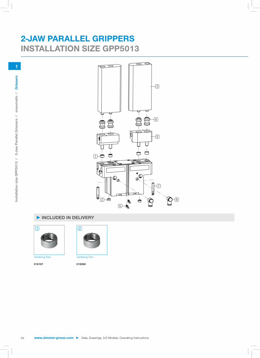
► TECHNICAL DRAWINGS
1 Gripper attachment
2 Energy supply
3 Fixing for gripper finger
6 Integrated slot for magnetic field sensor
7 Mounting block
bu Air purge connection option
dq Attachment option for customer-specific fittings
dt Adapter
du Gripper
ep Clamp for sensor
eq Switch cam adjustment
A Air connection (close)
B Air connection (open)
K Air connection, alternative (close)
L Air connection, alternative (open)
Inst
alla
tion
size
GPP
5013
/
2-Ja
w P
aral
lel G
rippe
rs /
pn
eum
atic
/
Grip
pers
Data, Drawings, 3-D Models, Operating Instructions ◄ www.zimmer-group.com
1
2
3
7
6
4
5
8
1
34
► INCLUDED IN DELIVERY
Centering Disc Centering Disc
018187 019280
1 2
2-JAW PARALLEL GRIPPERSINSTALLATION SIZE GPP5013
Inst
alla
tion
size
GPP
5013
/
2-Ja
w P
aral
lel G
rippe
rs /
pn
eum
atic
/
Grip
pers
www.zimmer-group.com ► Data, Drawings, 3-D Models, Operating Instructions

A
A 14.5
30°
9.5
24
35
64.5
11
125
3
5
6.5
10 H
7
A-A
2x
10h7
2x M
6x17
342
20
23
52
29
10
10.5 24
T15
1
35
► RECOMMENDED ACCESSORIES
Universal jaw aluminium Universal jaw steel Changeable jaw, loose-part-set
Changeable jaw, fi x-part Magnetic fi eld sensor Angled Cable 0,3 m - Connector M8
UB5013AL UB5013ST WB5013L WB5013F MFS103SKHC
Magnetic fi eld sensor Straight Cable 0,3 m - Connector M8
2-Position-Sensor Cable 0,3 m - Connector M8
Inductive proximity switch - Connector M8
Plug-in connector Angled Ca-ble 5m - Socket M8 (female)
Plug-in connector Straight Ca-ble 5m - Socket M8 (female)
MFS204SKHC MFSP2SKHC-01 NJ8-E2S KAW500 KAG500
Plug-in connector customiz-able Straight - Connector M8
Angled Fittings - Quick Connect Style
Straight Fittings - Quick Connect Style
Quick Exhaust Valve Pressure Safety Valve
S8-G-3 WV1-8X6 GV1-8X6 DEV06 DSV1-8
3 3 4 5 6
6 6 7
8 8
One universal jaw is required for each gripper jaw 3 For each gripper jaw, one interchangeable jaw loose part set 4and one interchangeable jaw fi xed part 5are needed
► TECHNICAL DRAWINGS ACCESSORIES
Inst
alla
tion
size
GPP
5013
/
2-Ja
w P
aral
lel G
rippe
rs /
pn
eum
atic
/
Grip
pers
Data, Drawings, 3-D Models, Operating Instructions ◄ www.zimmer-group.com
1
36
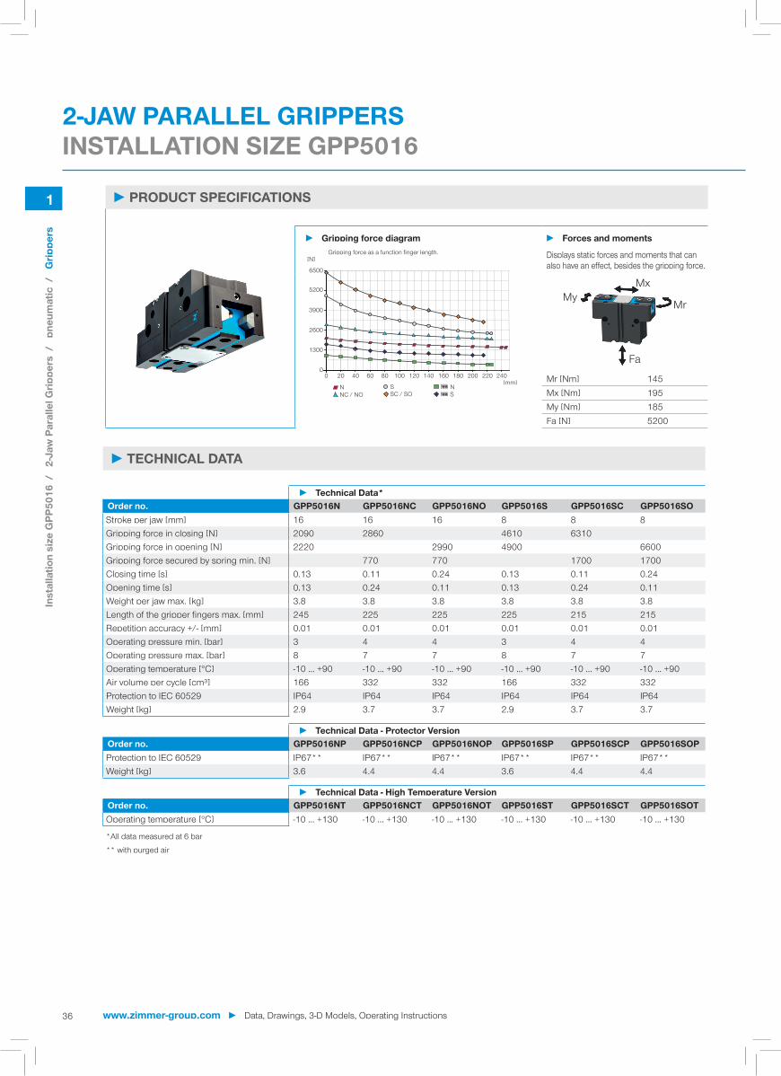
► PRODUCT SPECIFICATIONS
► Gripping force diagram ► Forces and moments
2600
5200
0
1300
3900
6500
0
[N]
[mm]NNC / NO
SSC / SO
NS
604020 80 100 120 140 160 180 200 220 240
Gripping force as a function finger length. Displays static forces and moments that can also have an effect, besides the gripping force.
MxMy
Mr
Fa
Mr [Nm] 145Mx [Nm] 195My [Nm] 185Fa [N] 5200
Order no. GPP5016N GPP5016NC GPP5016NO GPP5016S GPP5016SC GPP5016SOStroke per jaw [mm] 16 16 16 8 8 8Gripping force in closing [N] 2090 2860 4610 6310 Gripping force in opening [N] 2220 2990 4900 6600Gripping force secured by spring min. [N] 770 770 1700 1700Closing time [s] 0.13 0.11 0.24 0.13 0.11 0.24Opening time [s] 0.13 0.24 0.11 0.13 0.24 0.11Weight per jaw max. [kg] 3.8 3.8 3.8 3.8 3.8 3.8Length of the gripper fi ngers max. [mm] 245 225 225 225 215 215Repetition accuracy +/- [mm] 0.01 0.01 0.01 0.01 0.01 0.01Operating pressure min. [bar] 3 4 4 3 4 4Operating pressure max. [bar] 8 7 7 8 7 7Operating temperature [°C] -10 ... +90 -10 ... +90 -10 ... +90 -10 ... +90 -10 ... +90 -10 ... +90Air volume per cycle [cm³] 166 332 332 166 332 332Protection to IEC 60529 IP64 IP64 IP64 IP64 IP64 IP64Weight [kg] 2.9 3.7 3.7 2.9 3.7 3.7
► Technical Data*
Order no. GPP5016NP GPP5016NCP GPP5016NOP GPP5016SP GPP5016SCP GPP5016SOPProtection to IEC 60529 IP67** IP67** IP67** IP67** IP67** IP67**Weight [kg] 3.6 4.4 4.4 3.6 4.4 4.4
► Technical Data - Protector Version
Order no. GPP5016NT GPP5016NCT GPP5016NOT GPP5016ST GPP5016SCT GPP5016SOTOperating temperature [°C] -10 ... +130 -10 ... +130 -10 ... +130 -10 ... +130 -10 ... +130 -10 ... +130
*All data measured at 6 bar** with purged air
► Technical Data - High Temperature Version
2-JAW PARALLEL GRIPPERSINSTALLATION SIZE GPP5016
► TECHNICAL DATA
Inst
alla
tion
size
GPP
5016
/
2-Ja
w P
aral
lel G
rippe
rs /
pn
eum
atic
/
Grip
pers
www.zimmer-group.com ► Data, Drawings, 3-D Models, Operating Instructions

57.6 S 8
100±0.02 ø12h7
143
24.5 56
±0.0
2 ø1
2h7
75
192
37
79.2
72 68
117
2.2
58
74
100
125
39
26.5
2x 12h73
44
4x 14h7
4x M10x17
59
61 50
32
2x 5H7
8 5
48
4xM5
37
100±0.02
68±0
.02
79.2
74
58
54
51
72
77
49.4 N 16
A` B`
YX
1
A B
M5
2x G1/8"
19
26
4x M8DIN912*
2x M4DIN912*
1
1
X
4xM8x16
7
2x 12H7x31 22xM5
35
44
Y
45
3
3
35
B` A`
22xM5
2x 12H7x3
1
M519
32 28
77
18 39.2
2.2
A B
4x 14h7
43
53.5
42.8
44.8
54
87
35 31.6 61
229
16.5
3938
M5
1.1
Ø5
Ø8
O-RingØ5x1.5
2
1
37
NC / NO / SC / SO
N / S
Protector version
Hoseless air feed-through
► TECHNICAL DRAWINGS
1 Gripper attachment
2 Energy supply
3 Fixing for gripper finger
6 Integrated slot for magnetic field sensor
7 Mounting block
bu Air purge connection option
dq Attachment option for customer-specific fittings
dt Adapter
du Gripper
ep Clamp for sensor
eq Switch cam adjustment
A Air connection (close)
B Air connection (open)
K Air connection, alternative (close)
L Air connection, alternative (open)
Inst
alla
tion
size
GPP
5016
/
2-Ja
w P
aral
lel G
rippe
rs /
pn
eum
atic
/
Grip
pers
Data, Drawings, 3-D Models, Operating Instructions ◄ www.zimmer-group.com

1
2
3
7
6
4
5
8
1
38
► INCLUDED IN DELIVERY
Centering Disc Centering Disc
019387 019280
1 2
2-JAW PARALLEL GRIPPERSINSTALLATION SIZE GPP5016
Inst
alla
tion
size
GPP
5016
/
2-Ja
w P
aral
lel G
rippe
rs /
pn
eum
atic
/
Grip
pers
www.zimmer-group.com ► Data, Drawings, 3-D Models, Operating Instructions

A
A
81
16
30°
1032
170
18
11 14 H
7
4
409
A-A
16 32
40.5
14.6
52 4
2x
14h7
2x M
10x2
1
28.5
33
72
T30
1
39
► RECOMMENDED ACCESSORIES
Universal jaw aluminium Universal jaw steel Changeable jaw, loose-part-set
Changeable jaw, fi x-part Magnetic fi eld sensor Angled Cable 0,3 m - Connector M8
UB5016AL UB5016ST WB5016L WB5016F MFS103SKHC
Magnetic fi eld sensor Straight Cable 0,3 m - Connector M8
2-Position-Sensor Cable 0,3 m - Connector M8
Inductive proximity switch - Connector M8
Plug-in connector Angled Ca-ble 5m - Socket M8 (female)
Plug-in connector Straight Ca-ble 5m - Socket M8 (female)
MFS204SKHC MFSP2SKHC-01 NJ8-E2S KAW500 KAG500
Plug-in connector customiz-able Straight - Connector M8
Angled Fittings - Quick Connect Style
Straight Fittings - Quick Connect Style
Quick Exhaust Valve Pressure Safety Valve
S8-G-3 WV1-8X6 GV1-8X6 DEV06 DSV1-8
3 3 4 5 6
6 6 7
8 8
One universal jaw is required for each gripper jaw 3 For each gripper jaw, one interchangeable jaw loose part set 4and one interchangeable jaw fi xed part 5are needed
► TECHNICAL DRAWINGS ACCESSORIES
Inst
alla
tion
size
GPP
5016
/
2-Ja
w P
aral
lel G
rippe
rs /
pn
eum
atic
/
Grip
pers
Data, Drawings, 3-D Models, Operating Instructions ◄ www.zimmer-group.com

1
40
► PRODUCT SPECIFICATIONS
► Gripping force diagram ► Forces and moments
3600
7200
0
1800
5400
9000
0
[N]
[mm]NNC / NO
SSC / SO
NS
906030 120 150 180 210 240 270 300
Gripping force as a function finger length. Displays static forces and moments that can also have an effect, besides the gripping force.
MxMy
Mr
Fa
Mr [Nm] 180Mx [Nm] 205My [Nm] 225Fa [N] 7500
Order no. GPP5025N GPP5025NC GPP5025NO GPP5025S GPP5025SC GPP5025SOStroke per jaw [mm] 25 25 25 14 14 14Gripping force in closing [N] 3280 4510 6360 8730 Gripping force in opening [N] 3490 4710 6760 9130Gripping force secured by spring min. [N] 1220 1220 2370 2370Closing time [s] 0.33 0.28 0.57 0.33 0.28 0.57Opening time [s] 0.33 0.57 0.28 0.33 0.57 0.28Weight per jaw max. [kg] 7 7 7 7 7 7Length of the gripper fi ngers max. [mm] 310 265 265 265 220 220Repetition accuracy +/- [mm] 0.04 0.04 0.04 0.04 0.04 0.04Operating pressure min. [bar] 3 4 4 3 4 4Operating pressure max. [bar] 8 7 7 8 7 7Operating temperature [°C] -10 ... +90 -10 ... +90 -10 ... +90 -10 ... +90 -10 ... +90 -10 ... +90Air volume per cycle [cm³] 420 830 830 420 830 830Protection to IEC 60529 IP64 IP64 IP64 IP64 IP64 IP64Weight [kg] 6.1 7.65 7.65 6.1 7.65 7.65
► Technical Data*
Order no. GPP5025NP GPP5025NCP GPP5025NOP GPP5025SP GPP5025SCP GPP5025SOPProtection to IEC 60529 IP67** IP67** IP67** IP67** IP67** IP67**Weight [kg] 7.20 8.75 8.75 7.2 8.75 8.75
► Technical Data - Protector Version
Order no. GPP5025NT GPP5025NCT GPP5025NOT GPP5025ST GPP5025SCT GPP5025SOTOperating temperature [°C] -10 ... +130 -10 ... +130 -10 ... +130 -10 ... +130 -10 ... +130 -10 ... +130
*All data measured at 6 bar** with purged air
► Technical Data - High Temperature Version
2-JAW PARALLEL GRIPPERSINSTALLATION SIZE GPP5025
► TECHNICAL DATA
Inst
alla
tion
size
GPP
5025
/
2-Ja
w P
aral
lel G
rippe
rs /
pn
eum
atic
/
Grip
pers
www.zimmer-group.com ► Data, Drawings, 3-D Models, Operating Instructions

73.3 S 14
164
130±0.02 ø14h7
70
±0.0
2 ø1
4h7
39.5
82
26.5
48
100
82
130
84 82.5
72 96.7
33.5
234
2.2
141
68.8
77
1544
2x 14 h7
44 4x M12x14.5
4x 16h7
33.5
130±0.02
84±0
.02
96.7
72
82
6276
65
40±0.02 76
62.5 N 25
2x 6H76
51
11
4xM6
57
A B
M5 19
2x G1/8"6
2
4x M8DIN912*
2x M10DIN912*
1
144
Y
45
2x 14H7x4M5
2x M5
A'B'
1
2
19
X
4x M10x20
7
2x 14H7x4 2x M5
1
1 2
A' B'
Y
3
3
X
3535
32.534
91
2.2
22 46.7
A B119.2
290
2859
3742 7756
.3
58.367
43
4x 16h7
3938
M5
1.1
Ø5
Ø8
O-RingØ5x1.5
2
1
41
NC / NO / SC / SO
N / S
Protector version
Hoseless air feed-through
► TECHNICAL DRAWINGS
1 Gripper attachment
2 Energy supply
3 Fixing for gripper finger
6 Integrated slot for magnetic field sensor
7 Mounting block
bu Air purge connection option
dq Attachment option for customer-specific fittings
dt Adapter
du Gripper
ep Clamp for sensor
eq Switch cam adjustment
A Air connection (close)
B Air connection (open)
K Air connection, alternative (close)
L Air connection, alternative (open)
Inst
alla
tion
size
GPP
5025
/
2-Ja
w P
aral
lel G
rippe
rs /
pn
eum
atic
/
Grip
pers
Data, Drawings, 3-D Models, Operating Instructions ◄ www.zimmer-group.com

1
2
3
7
6
4
5
8
1
42
► INCLUDED IN DELIVERY
Centering Disc Centering Disc
030529 019387
1 2
2-JAW PARALLEL GRIPPERSINSTALLATION SIZE GPP5025
Inst
alla
tion
size
GPP
5025
/
2-Ja
w P
aral
lel G
rippe
rs /
pn
eum
atic
/
Grip
pers
www.zimmer-group.com ► Data, Drawings, 3-D Models, Operating Instructions

A
A
96
18
30°
1540
210
20
13.5
16 H
7
445
14
A-A
18.5 40
87
50
18.5
60 4
35.5
42
2x
16h7
2x M
12x2
5
T30
1
43
► RECOMMENDED ACCESSORIES
Universal jaw aluminium Universal jaw steel Changeable jaw, loose-part-set
Changeable jaw, fi x-part Magnetic fi eld sensor Angled Cable 0,3 m - Connector M8
UB5025AL UB5025ST WB5025L WB5025F MFS103SKHC
Magnetic fi eld sensor Straight Cable 0,3 m - Connector M8
2-Position-Sensor Cable 0,3 m - Connector M8
Inductive proximity switch - Connector M8
Plug-in connector Angled Ca-ble 5m - Socket M8 (female)
Plug-in connector Straight Ca-ble 5m - Socket M8 (female)
MFS204SKHC MFSP2SKHC-01 NJ8-E2S KAW500 KAG500
Plug-in connector customiz-able Straight - Connector M8
Angled Fittings - Quick Connect Style
Straight Fittings - Quick Connect Style
Quick Exhaust Valve Pressure Safety Valve
S8-G-3 WV1-8X8 GV1-8X8 DEV08 DSV1-8
3 3 4 5 6
6 6 7
8 8
One universal jaw is required for each gripper jaw 3 For each gripper jaw, one interchangeable jaw loose part set 4and one interchangeable jaw fi xed part 5are needed
► TECHNICAL DRAWINGS ACCESSORIES
Inst
alla
tion
size
GPP
5025
/
2-Ja
w P
aral
lel G
rippe
rs /
pn
eum
atic
/
Grip
pers
Data, Drawings, 3-D Models, Operating Instructions ◄ www.zimmer-group.com

1
44
► PRODUCT SPECIFICATIONS
► Gripping force diagram ► Forces and moments
5600
11200
0
2800
8400
14000
0
[N]
[mm]NNC / NO
SSC / SO
NS
906030 120 150 180 210 240 270 300 330 360
Gripping force as a function finger length. Displays static forces and moments that can also have an effect, besides the gripping force.
MxMy
Mr
Fa
Mr [Nm] 210Mx [Nm] 290My [Nm] 310Fa [N] 9500
Order no. GPP5030N GPP5030NC GPP5030NO GPP5030S GPP5030SC GPP5030SOStroke per jaw [mm] 30 30 30 17 17 17Gripping force in closing [N] 5000 6850 9600 13160 Gripping force in opening [N] 5210 7060 9990 13550Gripping force secured by spring min. [N] 1850 1850 3560 3560Closing time [s] 0.4 0.35 0.65 0.4 0.35 0.65Opening time [s] 0.4 0.65 0.35 0.4 0.65 0.35Weight per jaw max. [kg] 9.5 9.5 9.5 9.5 9.5 9.5Length of the gripper fi ngers max. [mm] 355 305 305 305 260 260Repetition accuracy +/- [mm] 0.04 0.04 0.04 0.04 0.04 0.04Operating pressure min. [bar] 3 4 4 3 4 4Operating pressure max. [bar] 8 7 7 8 7 7Operating temperature [°C] -10 ... +90 -10 ... +90 -10 ... +90 -10 ... +90 -10 ... +90 -10 ... +90Air volume per cycle [cm³] 745 1430 1430 745 1430 1430Protection to IEC 60529 IP64 IP64 IP64 IP64 IP64 IP64Weight [kg] 9.2 12 12 9.2 12 12
► Technical Data*
Order no. GPP5030NP GPP5030NCP GPP5030NOP GPP5030SP GPP5030SCP GPP5030SOPProtection to IEC 60529 IP67** IP67** IP67** IP67** IP67** IP67**Weight [kg] 10.9 13.7 13.7 10.9 13.7 13.7
► Technical Data - Protector Version
Order no. GPP5030NT GPP5030NCT GPP5030NOT GPP5030ST GPP5030SCT GPP5030SOTOperating temperature [°C] -10 ... +130 -10 ... +130 -10 ... +130 -10 ... +130 -10 ... +130 -10 ... +130
*All data measured at 6 bar** with purged air
► Technical Data - High Temperature Version
2-JAW PARALLEL GRIPPERSINSTALLATION SIZE GPP5030
► TECHNICAL DATA
Inst
alla
tion
size
GPP
5030
/
2-Ja
w P
aral
lel G
rippe
rs /
pn
eum
atic
/
Grip
pers
www.zimmer-group.com ► Data, Drawings, 3-D Models, Operating Instructions

81.1 S 17
160±0.02 ø16H7
192
48
80
±0.
02 ø
16H
7
96
79.3
85
115
57
35
9995.5
81.8 11
2.216
3.5
2.2
270
38
96
160
186
2x 16h7
4
160±0.02
96
81.8
95.5
±0.0
2
112.
15
38
81
93.5
86 72
68 N 30
44±0.02
4xM62x 8H7
67
11
8
4x 16h7
4x M12x174
4
A B
M5
2x G1/8"
19
26
X
A` B`
2x M52x 16H7x4
4x M12x25.51
1 2
7
4x M10DIN912*
2x M12DIN912*
1
1
Y
44
45B` A`
M5
2x 16H7x4
2x M5
1
19
3535
X 3
3
Y
39 55.7
42.5
25.3
107
2.2
A B
64.3
62.373
34
4x 16h7
338
70
136.8
32
3944.6 86
3938
M5
1.1
Ø5
Ø8
O-RingØ5x1.5
2
1
45
NC / NO / SC / SO
N / S
Protector version
Hoseless air feed-through
► TECHNICAL DRAWINGS
1 Gripper attachment
2 Energy supply
3 Fixing for gripper finger
6 Integrated slot for magnetic field sensor
7 Mounting block
bu Air purge connection option
dq Attachment option for customer-specific fittings
dt Adapter
du Gripper
ep Clamp for sensor
eq Switch cam adjustment
A Air connection (close)
B Air connection (open)
K Air connection, alternative (close)
L Air connection, alternative (open)
Inst
alla
tion
size
GPP
5030
/
2-Ja
w P
aral
lel G
rippe
rs /
pn
eum
atic
/
Grip
pers
Data, Drawings, 3-D Models, Operating Instructions ◄ www.zimmer-group.com

1
2
3
7
6
4
5
8
1
46
► INCLUDED IN DELIVERY
Centering Disc
030529
12
2-JAW PARALLEL GRIPPERSINSTALLATION SIZE GPP5030
Inst
alla
tion
size
GPP
5030
/
2-Ja
w P
aral
lel G
rippe
rs /
pn
eum
atic
/
Grip
pers
www.zimmer-group.com ► Data, Drawings, 3-D Models, Operating Instructions

A
A
109
18
30°
1544
230
20
13.5
16 H
7
450
14.5
A-A
18.5
91
44
20
52
63.5 4
2x
16h7
2x M
12x2
5
43.5
40
T30
1
47
► RECOMMENDED ACCESSORIES
Universal jaw aluminium Universal jaw steel Changeable jaw, loose-part-set
Changeable jaw, fi x-part Magnetic fi eld sensor Angled Cable 0,3 m - Connector M8
UB5030AL UB5030ST WB5030L WB5030F MFS103SKHC
Magnetic fi eld sensor Straight Cable 0,3 m - Connector M8
2-Position-Sensor Cable 0,3 m - Connector M8
Inductive proximity switch - Connector M8
Plug-in connector Angled Ca-ble 5m - Socket M8 (female)
Plug-in connector Straight Ca-ble 5m - Socket M8 (female)
MFS204SKHC MFSP2SKHC-01 NJ8-E2S KAW500 KAG500
Plug-in connector customiz-able Straight - Connector M8
Angled Fittings - Quick Connect Style
Straight Fittings - Quick Connect Style
Quick Exhaust Valve Pressure Safety Valve
S8-G-3 WV1-8X8 GV1-8X8 DEV08 DSV1-8
3 3 4 5 6
6 6 7
8 8
One universal jaw is required for each gripper jaw 3 For each gripper jaw, one interchangeable jaw loose part set 4and one interchangeable jaw fi xed part 5are needed
► TECHNICAL DRAWINGS ACCESSORIES
Inst
alla
tion
size
GPP
5030
/
2-Ja
w P
aral
lel G
rippe
rs /
pn
eum
atic
/
Grip
pers
Data, Drawings, 3-D Models, Operating Instructions ◄ www.zimmer-group.com

2
48
► Our products love the challenge!Extreme conditions, all over the world—our tried and tested components and systems give you limitless possibilities: Find the best product for your specifi c use: www.zimmer-group.com
HOW TO ORDER CORRECTLY
Order no. GPD5010
Basis version N
► The product order numbers are arranged according to this diagram:
High force S
For external gripping, self-locking, spring closing C
For internal gripping, self-locking, spring opening O
Protector version IP67 for use in adverse environments (with purged air) P
temperature-resistant version to 130 °C T
3-JAW CONCENTRIC GRIPPERSSERIES GPD5000
► PRODUCT ADVANTAGES
“The Universal One” ► Up to 30% more gripping force than the benchmark
► 10% more static forces and moments than the benchmark
► Gripper fi ngers up to 10% longer than the bench-mark
► Gripper fi ngers weight up to 15% higher than the benchmark
► Sealed guide IP64 / Protector version IP67 (with purged air)
► Protected against corrosion
► Up to 30 million cycles without maintenance
► THE BEST PRODUCT FOR YOUR APPLICATION
www.zimmer-group.com ► Data, Drawings, 3-D Models, Operating Instructions
Serie
s G
PD50
00 /
3-
Jaw
Con
cent
ric G
rippe
rs /
pn
eum
atic
/
Grip
pers

2
567
8
19
3
42
49
Gripping force: arithmetic sum of the individual forces occuring at the jaws
Closing/opening time: Time required for the gripper jaws to travel the entire stroke distance
Repeatability: at end stops after 50/100 consecutive cycles
Cycle: Path that the pistons travel for a complete opening and closing movement
Maintenance: recommended at 30 mil. cycles (please see the installation instructions, download from www.zimmer-group.com)
► BENEFITS IN DETAIL
1Positively driven wedge hook transmission - high forces and moments capacity - Synchronized gripper jaw movement
2Gripper jaw - DLC coated to protect against corrosion - Gripper fi ngers mounted using removable centring sleeves - Lubricated for life via incorporated lubrication slots
3Mounting block - mounting for inductive proximity switch
4Integrated gripping force safety device - Spring built into cylinder chamber as an energy store
5Sensing slot - mounting and positioning of magnetic fi eld sensors
6Mounting and positioning - Alternatively, on several sides for customized mounting - Pneumatic and electrical versions identical apart from height
7Drive - Double-acting pneumatic rotor cylinder
8Steel Linear Guide - Steel in steel guide - Enables use of extremely long gripper fi ngers
9Dual lip seal - IP64 and up to IP67 (with purged air) for Protector version - Prevents grease from being squeezed out, increasing service life
► TERMS
Data, Drawings, 3-D Models, Operating Instructions ◄ www.zimmer-group.com
Serie
s G
PD50
00 /
3-
Jaw
Con
cent
ric G
rippe
rs /
pn
eum
atic
/
Grip
pers
2
50
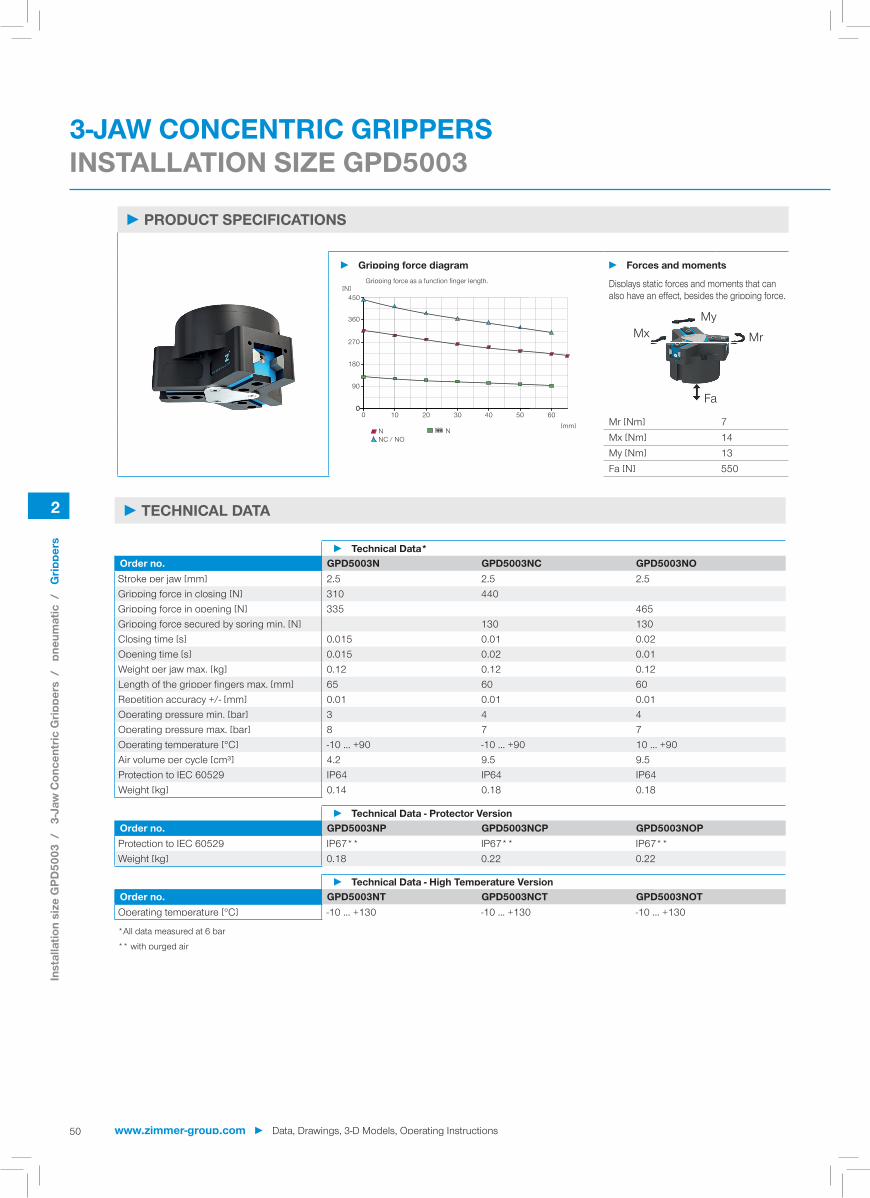
► PRODUCT SPECIFICATIONS
► Gripping force diagram ► Forces and moments
180
360
90
270
450
0302010 40 50 600
0
[N]
[mm]NNC / NO
N
Gripping force as a function finger length. Displays static forces and moments that can also have an effect, besides the gripping force.
MxMy
Mr
Fa
Mr [Nm] 7Mx [Nm] 14My [Nm] 13Fa [N] 550
Order no. GPD5003N GPD5003NC GPD5003NOStroke per jaw [mm] 2.5 2.5 2.5Gripping force in closing [N] 310 440 Gripping force in opening [N] 335 465Gripping force secured by spring min. [N] 130 130Closing time [s] 0.015 0.01 0.02Opening time [s] 0.015 0.02 0.01Weight per jaw max. [kg] 0.12 0.12 0.12Length of the gripper fi ngers max. [mm] 65 60 60Repetition accuracy +/- [mm] 0.01 0.01 0.01Operating pressure min. [bar] 3 4 4Operating pressure max. [bar] 8 7 7Operating temperature [°C] -10 ... +90 -10 ... +90 10 ... +90Air volume per cycle [cm³] 4.2 9.5 9.5Protection to IEC 60529 IP64 IP64 IP64Weight [kg] 0.14 0.18 0.18
► Technical Data*
Order no. GPD5003NP GPD5003NCP GPD5003NOPProtection to IEC 60529 IP67** IP67** IP67**Weight [kg] 0.18 0.22 0.22
► Technical Data - Protector Version
Order no. GPD5003NT GPD5003NCT GPD5003NOTOperating temperature [°C] -10 ... +130 -10 ... +130 -10 ... +130
*All data measured at 6 bar** with purged air
► Technical Data - High Temperature Version
3-JAW CONCENTRIC GRIPPERSINSTALLATION SIZE GPD5003
► TECHNICAL DATA
Inst
alla
tion
size
GPD
5003
/
3-Ja
w C
once
ntric
Grip
pers
/
pneu
mat
ic /
G
rippe
rs
www.zimmer-group.com ► Data, Drawings, 3-D Models, Operating Instructions

34.5
12
30°
36±0.02
27.2
16.2
24
15.219.525
35.2
44
1.2
9.8
13
R6
3
8±0.
1
2.3
21.9
7
10.8
6x M2.5x4
6x 4 h7
22
1023.4
14.5
2.5
3x 1.5H7
3x M2
4 3.5
17.5
24.5
B A 2xM5 2
X
3x 3.2
2x 2H7x10
B' A'
1
1
2x M3 2
3x M3DIN912*
Y 1
6
45
M5
19
Y
3
3
3535
X
11.517
27.2
7.2
1.2
13.9AB
22
6x 4h7
2726
32.2
24.5
14.5
11.5
19
8
19.7
3938
M3
0.8
Ø3
Ø5
O-RingØ3x1
2
2
51
NC / NO
N
Protector version
Hoseless air feed-through
► TECHNICAL DRAWINGS
1 Gripper attachment
2 Energy supply
3 Fixing for gripper finger
6 Integrated slot for magnetic field sensor
bu Air purge connection option
dq Attachment option for customer-specific fittings
dt Adapter
du Gripper
eq Switch cam adjustment
A Air connection (close)
B Air connection (open)
K Air connection, alternative (close)
L Air connection, alternative (open)
Inst
alla
tion
size
GPD
5003
/
3-Ja
w C
once
ntric
Grip
pers
/
pneu
mat
ic /
G
rippe
rs
Data, Drawings, 3-D Models, Operating Instructions ◄ www.zimmer-group.com

1
2
3
4
2
52
► INCLUDED IN DELIVERY
Centering Disc
DST06510
1
3-JAW CONCENTRIC GRIPPERSINSTALLATION SIZE GPD5003
Inst
alla
tion
size
GPD
5003
/
3-Ja
w C
once
ntric
Grip
pers
/
pneu
mat
ic /
G
rippe
rs
www.zimmer-group.com ► Data, Drawings, 3-D Models, Operating Instructions

A
A
23
4
30°
48
45
5
2.7 4 H
7
210
4
A-A
6
17.2
5
22
0 ... 33
2.5
4.9
3xM
3
5
2
53
► RECOMMENDED ACCESSORIES
Universal jaw aluminium Universal jaw steel Pressure piece N / S Pressure piece NC / NO / SC / SO
Rubber Coated Tape Smooth
UB5003AL UB5003ST ADS5004-01 ADS5004-02 KF50G
Rubber Coated Tape Knobbed
Magnetic fi eld sensor Angled Cable 0,3 m - Connector M8
Magnetic fi eld sensor Straight Cable 0,3 m - Connector M8
2-Position-Sensor Cable 0,3 m - Connector M8
Plug-in connector Angled Ca-ble 5m - Socket M8 (female)
KF50N MFS103SKHC MFS204SKHC MFSP2SKHC-01 KAW500
Plug-in connector Straight Ca-ble 5m - Socket M8 (female)
Plug-in connector customiz-able Straight - Connector M12
Angled Fittings - Barb Style Connection
Straight Fittings - Barb Style Connection
Pressure Safety Valve
KAG500 S12-G-3 WVM3 GVM3 DSV1-8
2 2
3 3 3
4 4
One universal jaw is required for each gripper jaw 2
Gripper is fastened via the pressure piece
► TECHNICAL DRAWINGS ACCESSORIES
Inst
alla
tion
size
GPD
5003
/
3-Ja
w C
once
ntric
Grip
pers
/
pneu
mat
ic /
G
rippe
rs
Data, Drawings, 3-D Models, Operating Instructions ◄ www.zimmer-group.com

2
54
► PRODUCT SPECIFICATIONS
► Gripping force diagram ► Forces and moments
600
1200
0
300
900
1500
02010 30 40 50 60 70 80
[mm]NNC / NO
SSC / SO
NS
[N]Gripping force as a function finger length. Displays static forces and moments that can
also have an effect, besides the gripping force.
MxMy
Mr
Fa
Mr [Nm] 14Mx [Nm] 29My [Nm] 23Fa [N] 750
Order no. GPD5004N GPD5004NC GPD5004NO GPD5004S GPD5004SC GPD5004SOStroke per jaw [mm] 4 4 4 2 2 2Gripping force in closing [N] 460 650 1010 1430 Gripping force in opening [N] 500 690 1100 1520Gripping force secured by spring min. [N] 190 190 420 420Closing time [s] 0.025 0.018 0.028 0.025 0.018 0.028Opening time [s] 0.025 0.028 0.018 0.025 0.028 0.018Weight per jaw max. [kg] 0.2 0.2 0.2 0.2 0.2 0.2Length of the gripper fi ngers max. [mm] 80 75 75 75 70 70Repetition accuracy +/- [mm] 0.01 0.01 0.01 0.01 0.01 0.01Operating pressure min. [bar] 3 4 4 3 4 4Operating pressure max. [bar] 8 7 7 8 7 7Operating temperature [°C] -10 ... +90 -10 ... +90 -10 ... +90 -10 ... +90 -10 ... +90 -10 ... +90Air volume per cycle [cm³] 11 21 21 11 21 21Protection to IEC 60529 IP64 IP64 IP64 IP64 IP64 IP64Weight [kg] 0.27 0.33 0.33 0.27 0.33 0.33
► Technical Data*
Order no. GPD5004NP GPD5004NCP GPD5004NOP GPD5004SP GPD5004SCP GPD5004SOPProtection to IEC 60529 IP67** IP67** IP67** IP67** IP67** IP67**Weight [kg] 0.35 0.41 0.41 0.35 0.41 0.41
► Technical Data - Protector Version
Order no. GPD5004NT GPD5004NCT GPD5004NOT GPD5004ST GPD5004SCT GPD5004SOTOperating temperature [°C] -10 ... +130 -10 ... +130 -10 ... +130 -10 ... +130 -10 ... +130 -10 ... +130
*All data measured at 6 bar** with purged air
► Technical Data - High Temperature Version
3-JAW CONCENTRIC GRIPPERSINSTALLATION SIZE GPD5004
► TECHNICAL DATA
Inst
alla
tion
size
GPD
5004
/
3-Ja
w C
once
ntric
Grip
pers
/
pneu
mat
ic /
G
rippe
rs
www.zimmer-group.com ► Data, Drawings, 3-D Models, Operating Instructions

44
N4
21
S2
33.5
24
45±0.02
15
30°
18.5
36
30
20.126
.5
32.5
544.5
1.2
52
3.3
12.3
3.3
R8
15 N
17 S
12±0
.02
19
12.3
26.8
29.5
2x 2H7
4
3x M2
3.5
6x 5h7
6x M3x5.5
22
13
8.5
30.5
B A 2x M5 2
X
B` A`
2x M3
2x 3H7x12
3x M4x10
1
1
2
Y3x M3DIN912*
145
6M5
19
X
35
35
Y3
3
16
34
1.2
9.622
.05
19B A
22.7
22
17.9
16.9
6x 5h7
42.5 2332
24
14.5
11.3
3938
M3
0.8
Ø3
Ø5
O-RingØ3x1
2
2
55
NC / NO / SC / SO
N / S
Protector version
Hoseless air feed-through
► TECHNICAL DRAWINGS
1 Gripper attachment
2 Energy supply
3 Fixing for gripper finger
6 Integrated slot for magnetic field sensor
bu Air purge connection option
dq Attachment option for customer-specific fittings
dt Adapter
du Gripper
eq Switch cam adjustment
A Air connection (close)
B Air connection (open)
K Air connection, alternative (close)
L Air connection, alternative (open)
Inst
alla
tion
size
GPD
5004
/
3-Ja
w C
once
ntric
Grip
pers
/
pneu
mat
ic /
G
rippe
rs
Data, Drawings, 3-D Models, Operating Instructions ◄ www.zimmer-group.com

1
2
3
4
56
2
56
► INCLUDED IN DELIVERY
Centering Disc
015761
1
3-JAW CONCENTRIC GRIPPERSINSTALLATION SIZE GPD5004
Inst
alla
tion
size
GPD
5004
/
3-Ja
w C
once
ntric
Grip
pers
/
pneu
mat
ic /
G
rippe
rs
www.zimmer-group.com ► Data, Drawings, 3-D Models, Operating Instructions

A
A
30
6.5
30°
512
50
6
3.4 5 H
7
215
4.5
A-A
17 2
11
12
2x
5h7
2x M
3x9.
5
28
6 12
5.5
16.5
T8
22 26
8
30 ... 33
3.1
3xM
3
5
2
57
► RECOMMENDED ACCESSORIES
Universal jaw aluminium Universal jaw steel Pressure piece N / S Pressure piece NC / NO / SC / SO
Changeable jaw, loose-part-set
UB5004AL UB5004ST ADS5004-01 ADS5004-02 WB5004L
Changeable jaw, fi x-part Magnetic fi eld sensor Angled Cable 0,3 m - Connector M8
Magnetic fi eld sensor Straight Cable 0,3 m - Connector M8
2-Position-Sensor Cable 0,3 m - Connector M8
Plug-in connector Angled Ca-ble 5m - Socket M8 (female)
WB5004F MFS103SKHC MFS204SKHC MFSP2SKHC-01 KAW500
Plug-in connector Straight Ca-ble 5m - Socket M8 (female)
Plug-in connector customiz-able Straight - Connector M12
Angled Fittings - Quick Connect Style
Straight Fittings - Quick Connect Style
Pressure Safety Valve
KAG500 S12-G-3 WVM5 GVM5 DSV1-8
2 2 3
4 5 5 5
6 6
One universal jaw is required for each gripper jaw 2 For each gripper jaw, one interchangeable jaw loose part set 3and one interchangeable jaw fi xed part 4are needed
Gripper is fastened via the pressure piece
► TECHNICAL DRAWINGS ACCESSORIES
Inst
alla
tion
size
GPD
5004
/
3-Ja
w C
once
ntric
Grip
pers
/
pneu
mat
ic /
G
rippe
rs
Data, Drawings, 3-D Models, Operating Instructions ◄ www.zimmer-group.com

2
58
► PRODUCT SPECIFICATIONS
► Gripping force diagram ► Forces and moments
920
1840
0
460
1380
0302010 40 50 60 70 80 90 100
[N]
[mm]NNC / NO
SSC / SO
NS
2300
Gripping force as a function finger length. Displays static forces and moments that can also have an effect, besides the gripping force.
MxMy
Mr
Fa
Mr [Nm] 43Mx [Nm] 70My [Nm] 46Fa [N] 1250
Order no. GPD5006N GPD5006NC GPD5006NO GPD5006S GPD5006SC GPD5006SOStroke per jaw [mm] 6 6 6 3 3 3Gripping force in closing [N] 740 1020 1620 2240 Gripping force in opening [N] 800 1080 1750 2370Gripping force secured by spring min. [N] 280 280 620 620Closing time [s] 0.028 0.018 0.038 0.028 0.018 0.038Opening time [s] 0.028 0.038 0.018 0.028 0.038 0.018Weight per jaw max. [kg] 0.4 0.4 0.4 0.4 0.4 0.4Length of the gripper fi ngers max. [mm] 100 90 90 90 85 85Repetition accuracy +/- [mm] 0.01 0.01 0.01 0.01 0.01 0.01Operating pressure min. [bar] 3 4 4 3 4 4Operating pressure max. [bar] 8 7 7 8 7 7Operating temperature [°C] -10 ... +90 -10 ... +90 -10 ... +90 -10 ... +90 -10 ... +90 -10 ... +90Air volume per cycle [cm³] 22 43 43 22 43 43Protection to IEC 60529 IP64 IP64 IP64 IP64 IP64 IP64Weight [kg] 0.48 0.58 0.58 0.48 0.58 0.58
► Technical Data*
Order no. GPD5006NP GPD5006NCP GPD5006NOP GPD5006SP GPD5006SCP GPD5006SOPProtection to IEC 60529 IP67** IP67** IP67** IP67** IP67** IP67**Weight [kg] 0.61 0.71 0.71 0.61 0.71 0.71
► Technical Data - Protector Version
Order no. GPD5006NT GPD5006NCT GPD5006NOT GPD5006ST GPD5006SCT GPD5006SOTOperating temperature [°C] -10 ... +130 -10 ... +130 -10 ... +130 -10 ... +130 -10 ... +130 -10 ... +130
*All data measured at 6 bar** with purged air
► Technical Data - High Temperature Version
3-JAW CONCENTRIC GRIPPERSINSTALLATION SIZE GPD5006
► TECHNICAL DATA
Inst
alla
tion
size
GPD
5006
/
3-Ja
w C
once
ntric
Grip
pers
/
pneu
mat
ic /
G
rippe
rs
www.zimmer-group.com ► Data, Drawings, 3-D Models, Operating Instructions

N6
S3
24.5
56
38
18
56±0.02
41.5
25
36
11
17.5
34.1
30.8
56.8
1.5
31.8
30°
64
24.839
.313
±0.0
2
21.5
17.5
6x 6h7
6x M4x62.
52.
6
15
415
4
28
2x 2.5H7
4 3.5
3xM2.5
31.6
R8
35
X
2x M5 2AB
X
2x M4
3x M6x13
2
1
1
7
B` A`
2x 4H7x12
3x M5DIN912*
1Y
6
44M5
19
45
3
3
Y35
35
11.3
18.325
.843.3
1.5
20.6
B A
6x 6h7
2.5
2.5
30.5
23.5 25
49.5
28
16.5
11
38.4 23
6
3938
M4
1.2
Ø4
Ø6
O-RingØ6x1
2
2
59
NC / NO / SC / SO
N / S
Protector version
Hoseless air feed-through
► TECHNICAL DRAWINGS
1 Gripper attachment
2 Energy supply
3 Fixing for gripper finger
6 Integrated slot for magnetic field sensor
7 Mounting block
bu Air purge connection option
dq Attachment option for customer-specific fittings
dt Adapter
du Gripper
ep Clamp for sensor
eq Switch cam adjustment
A Air connection (close)
B Air connection (open)
K Air connection, alternative (close)
L Air connection, alternative (open)
Inst
alla
tion
size
GPD
5006
/
3-Ja
w C
once
ntric
Grip
pers
/
pneu
mat
ic /
G
rippe
rs
Data, Drawings, 3-D Models, Operating Instructions ◄ www.zimmer-group.com

1
2
3
4
56
7
2
60
► INCLUDED IN DELIVERY
Centering Disc
024230
1
3-JAW CONCENTRIC GRIPPERSINSTALLATION SIZE GPD5006
Inst
alla
tion
size
GPD
5006
/
3-Ja
w C
once
ntric
Grip
pers
/
pneu
mat
ic /
G
rippe
rs
www.zimmer-group.com ► Data, Drawings, 3-D Models, Operating Instructions

A
A
33
8
30°
513
65
8
4.5
6 H
7
2.520
4.5
A-A
31.5
136.5
7
19
22 2.5
12.5
15
2x
6h7
2x M
4x11
T15
2x
4H7
611
2x
4m6
C/O 43.2N/S 56.7
28 32
12
3xM
5
7.5
4.1
0 ... 44
4
2
61
► RECOMMENDED ACCESSORIES
Universal jaw aluminium Universal jaw steel Pressure piece N / S Pressure piece NC / NO / SC / SO
Changeable jaw, loose-part-set
UB5006AL UB5006ST ADS5004-01 ADS5004-02 WB5006L
Changeable jaw, fi x-part Magnetic fi eld sensor Angled Cable 0,3 m - Connector M8
Magnetic fi eld sensor Straight Cable 0,3 m - Connector M8
2-Position-Sensor Cable 0,3 m - Connector M8
Inductive Proximity Switch Cable 0,3 m - Connector M8
WB5006F MFS103SKHC MFS204SKHC MFSP2SKHC-01 NJ4-E2SK-01
Plug-in connector Straight Ca-ble 5m - Socket M8 (female)
Angled Fittings - Quick Connect Style
Pressure Safety Valve Compensation module N / S
Compensation module NC / NO / SC / SO
KAG500 WVM5 DSV1-8 ZUB5006DNS ZUB5006DCO
2 2 3
4 5 5 5 6
7
One universal jaw is required for each gripper jaw 2 For each gripper jaw, one interchangeable jaw loose part set 3and one interchangeable jaw fi xed part 4are needed
Compensation module for compensating for the height differences between the pneumatic and electric gripper version
Gripper is fastened via the pressure piece
► TECHNICAL DRAWINGS ACCESSORIES
Inst
alla
tion
size
GPD
5006
/
3-Ja
w C
once
ntric
Grip
pers
/
pneu
mat
ic /
G
rippe
rs
Data, Drawings, 3-D Models, Operating Instructions ◄ www.zimmer-group.com

2
62
► PRODUCT SPECIFICATIONS
► Gripping force diagram ► Forces and moments
1520
3040
760
2280
3800
0
[N]
00
[mm]NNC / NO
SSC / SO
NS
302010 40 50 60 70 80 90 100 110 120
Gripping force as a function finger length. Displays static forces and moments that can also have an effect, besides the gripping force.
MxMy
Mr
Fa
Mr [Nm] 60Mx [Nm] 105My [Nm] 65Fa [N] 1900
Order no. GPD5008N GPD5008NC GPD5008NO GPD5008S GPD5008SC GPD5008SOStroke per jaw [mm] 8 8 8 4 4 4Gripping force in closing [N] 1260 1690 2780 3730 Gripping force in opening [N] 1340 1770 2960 3910Gripping force secured by spring min. [N] 430 430 950 950Closing time [s] 0.048 0.035 0.055 0.048 0.035 0.055Opening time [s] 0.048 0.055 0.035 0.048 0.055 0.035Weight per jaw max. [kg] 0.7 0.7 0.7 0.7 0.7 0.7Length of the gripper fi ngers max. [mm] 125 115 115 115 105 105Repetition accuracy +/- [mm] 0.01 0.01 0.01 0.01 0.01 0.01Operating pressure min. [bar] 3 4 4 3 4 4Operating pressure max. [bar] 8 7 7 8 7 7Operating temperature [°C] -10 ... +90 -10 ... +90 -10 ... +90 -10 ... +90 -10 ... +90 -10 ... +90Air volume per cycle [cm³] 51 90 90 51 90 90Protection to IEC 60529 IP64 IP64 IP64 IP64 IP64 IP64Weight [kg] 0.83 1 1 0.83 1 1
► Technical Data*
Order no. GPD5008NP GPD5008NCP GPD5008NOP GPD5008SP GPD5008SCP GPD5008SOPProtection to IEC 60529 IP67** IP67** IP67** IP67** IP67** IP67**Weight [kg] 1.03 1.2 1.2 1.03 1.2 1.2
► Technical Data - Protector Version
Order no. GPD5008NT GPD5008NCT GPD5008NOT GPD5008ST GPD5008SCT GPD5008SOTOperating temperature [°C] -10 ... +130 -10 ... +130 -10 ... +130 -10 ... +130 -10 ... +130 -10 ... +130
*All data measured at 6 bar** with purged air
► Technical Data - High Temperature Version
3-JAW CONCENTRIC GRIPPERSINSTALLATION SIZE GPD5008
► TECHNICAL DATA
Inst
alla
tion
size
GPD
5008
/
3-Ja
w C
once
ntric
Grip
pers
/
pneu
mat
ic /
G
rippe
rs
www.zimmer-group.com ► Data, Drawings, 3-D Models, Operating Instructions

30
S4
N8
70
47
26
16±0
.02
22
80
28.335.345
.364.3
1.5
42
51.538
32
18
30°70±0.02
39.1
6x 8h7
6x M5x82.5
2.6
21
13
39.5
R8.5
5.1
19.1
19.1
5.1
2x 3H7
3xM2.5
3.54
36
43
B A 2x M5 2
X
B´ A`
2x M4
3x M8x171
1
2
7
2x 5H7x17
3x M6DIN912*
1Y
44
6
M5
19
45
3
3
Y
35
35
X
20.330
.349.3
1.5
24.1
13.3
B A
27.5 2934.5 2.5
2.5 6x 8h7
947
.5 1662
19.5
33
13
3938
M4
1.2
Ø4
Ø6
O-RingØ6x1
2
2
63
NC / NO / SC / SO
N / S
Protector version
Hoseless air feed-through
► TECHNICAL DRAWINGS
1 Gripper attachment
2 Energy supply
3 Fixing for gripper finger
6 Integrated slot for magnetic field sensor
7 Mounting block
bu Air purge connection option
dq Attachment option for customer-specific fittings
dt Adapter
du Gripper
ep Clamp for sensor
eq Switch cam adjustment
A Air connection (close)
B Air connection (open)
K Air connection, alternative (close)
L Air connection, alternative (open)
Inst
alla
tion
size
GPD
5008
/
3-Ja
w C
once
ntric
Grip
pers
/
pneu
mat
ic /
G
rippe
rs
Data, Drawings, 3-D Models, Operating Instructions ◄ www.zimmer-group.com

1
2
3
4
56
7
2
64
► INCLUDED IN DELIVERY
Centering Disc
024231
1
3-JAW CONCENTRIC GRIPPERSINSTALLATION SIZE GPD5008
Inst
alla
tion
size
GPD
5008
/
3-Ja
w C
once
ntric
Grip
pers
/
pneu
mat
ic /
G
rippe
rs
www.zimmer-group.com ► Data, Drawings, 3-D Models, Operating Instructions

A
A
25
616
41
30°
11.5
10
80
2.5
4.5
5.5
8 H
7
A-A
38
8.5 16
8.5
23.5 16
.5
28
2x M
5x13
2x
8h7
17
2.5
T15
15
2x
5m6
6
2x5H
7
C/O 39.7N/S 54.7
13
4035
9
3xM
6
2.1
3.2 ... 8.25
4
2
65
► RECOMMENDED ACCESSORIES
Universal jaw aluminium Universal jaw steel Pressure piece N / S Pressure piece NC / NO / SC / SO
Changeable jaw, loose-part-set
UB5008AL UB5008ST ADS5004-01 ADS5004-02 WB5008L
Changeable jaw, fi x-part Magnetic fi eld sensor Angled Cable 0,3 m - Connector M8
Magnetic fi eld sensor Straight Cable 0,3 m - Connector M8
2-Position-Sensor Cable 0,3 m - Connector M8
Inductive Proximity Switch Cable 0,3 m - Connector M8
WB5008F MFS103SKHC MFS204SKHC MFSP2SKHC-01 NJ4-E2SK-01
Plug-in connector Straight Ca-ble 5m - Socket M8 (female)
Angled Fittings - Quick Connect Style
Pressure Safety Valve Compensation module N / S
Compensation module NC / NO / SC / SO
KAG500 WVM5 DSV1-8 ZUB5008DNS ZUB5008DCO
2 2 3
4 5 5 5 6
7
One universal jaw is required for each gripper jaw 2 For each gripper jaw, one interchangeable jaw loose part set 3and one interchangeable jaw fi xed part 4are needed
Compensation module for compensating for the height differences between the pneumatic and electric gripper version
Gripper is fastened via the pressure piece
► TECHNICAL DRAWINGS ACCESSORIES
Inst
alla
tion
size
GPD
5008
/
3-Ja
w C
once
ntric
Grip
pers
/
pneu
mat
ic /
G
rippe
rs
Data, Drawings, 3-D Models, Operating Instructions ◄ www.zimmer-group.com

2
66
► PRODUCT SPECIFICATIONS
► Gripping force diagram ► Forces and moments
2800
5600
1400
4200
7000
0
[N]
0 302010 40 50 60 70 80 90 100 110 120130 140 150160[mm]N
NC / NOSSC / SO
NS
Gripping force as a function finger length. Displays static forces and moments that can also have an effect, besides the gripping force.
MxMy
Mr
Fa
Mr [Nm] 75Mx [Nm] 125My [Nm] 95Fa [N] 2700
Order no. GPD5010N GPD5010NC GPD5010NO GPD5010S GPD5010SC GPD5010SOStroke per jaw [mm] 10 10 10 5 5 5Gripping force in closing [N] 2290 3140 5050 6930 Gripping force in opening [N] 2400 3250 5280 7160Gripping force secured by spring min. [N] 850 850 1880 1880Closing time [s] 0.095 0.095 0.19 0.095 0.095 0.19Opening time [s] 0.095 0.19 0.095 0.095 0.19 0.095Weight per jaw max. [kg] 1.3 1.3 1.3 1.3 1.3 1.3Length of the gripper fi ngers max. [mm] 160 145 145 145 130 130Repetition accuracy +/- [mm] 0.01 0.01 0.01 0.01 0.01 0.01Operating pressure min. [bar] 3 4 4 3 4 4Operating pressure max. [bar] 8 7 7 8 7 7Operating temperature [°C] -10 ... +90 -10 ... +90 -10 ... +90 -10 ... +90 -10 ... +90 -10 ... +90Air volume per cycle [cm³] 100 200 200 100 200 200Protection to IEC 60529 IP64 IP64 IP64 IP64 IP64 IP64Weight [kg] 1.45 1.9 1.9 1.45 1.9 1.9
► Technical Data*
Order no. GPD5010NP GPD5010NCP GPD5010NOP GPD5010SP GPD5010SCP GPD5010SOPProtection to IEC 60529 IP67** IP67** IP67** IP67** IP67** IP67**Weight [kg] 1.8 2.23 2.23 1.8 2.23 2.23
► Technical Data - Protector Version
Order no. GPD5010NT GPD5010NCT GPD5010NOT GPD5010ST GPD5010SCT GPD5010SOTOperating temperature [°C] -10 ... +130 -10 ... +130 -10 ... +130 -10 ... +130 -10 ... +130 -10 ... +130
*All data measured at 6 bar** with purged air
► Technical Data - High Temperature Version
3-JAW CONCENTRIC GRIPPERSINSTALLATION SIZE GPD5010
► TECHNICAL DATA
Inst
alla
tion
size
GPD
5010
/
3-Ja
w C
once
ntric
Grip
pers
/
pneu
mat
ic /
G
rippe
rs
www.zimmer-group.com ► Data, Drawings, 3-D Models, Operating Instructions

90
N10
38
S5
58.5
90±0.02
24
30°
426447
.5
50
36.348
.859.179
.3
1.7
100
20±0
.02
27.5
32.8
6x 10h7
6x M6x933.
1
52.9
16
25
5.9
21.9
21.9
5.9
48.3
R12
40
5
3xM3
2x 4H7
5
53.5
B A 2x G1/8" 2
Y3x M6DIN912*
1
M5
19
44
6
45
B` A`
2x M5
3x M8x18
7
2
1
1
2x 5H7x18
X
3
3Y
35
35
X
28.839
.159.3
1.7
16.3
32.9B A
22
39
16
77
1059 20
28.8
30.537 3
3 6x 10h7
3938
M5
1.1
Ø5
Ø8
O-RingØ5x1.5
2
2
67
NC / NO / SC / SO
N / S
Protector version
Hoseless air feed-through
► TECHNICAL DRAWINGS
1 Gripper attachment
2 Energy supply
3 Fixing for gripper finger
6 Integrated slot for magnetic field sensor
7 Mounting block
bu Air purge connection option
dq Attachment option for customer-specific fittings
dt Adapter
du Gripper
ep Clamp for sensor
eq Switch cam adjustment
A Air connection (close)
B Air connection (open)
K Air connection, alternative (close)
L Air connection, alternative (open)
Inst
alla
tion
size
GPD
5010
/
3-Ja
w C
once
ntric
Grip
pers
/
pneu
mat
ic /
G
rippe
rs
Data, Drawings, 3-D Models, Operating Instructions ◄ www.zimmer-group.com

1
2
3
4
56
7
2
68
► INCLUDED IN DELIVERY
Centering Disc
018187
1
3-JAW CONCENTRIC GRIPPERSINSTALLATION SIZE GPD5010
Inst
alla
tion
size
GPD
5010
/
3-Ja
w C
once
ntric
Grip
pers
/
pneu
mat
ic /
G
rippe
rs
www.zimmer-group.com ► Data, Drawings, 3-D Models, Operating Instructions

A
A
51
12.5
30°
720
30
11
100
3
5
6.5 10
H7
A-A
45
209.5
10.5
28
19
35 3
2x
10h7
2x M
6x15
22T15
15
2x
5m6
2x
5H7
6
C/O 26.2N/S 46.2
45 50
15
3xM
6
9
4.8 ... 9.85
4
2
69
► RECOMMENDED ACCESSORIES
Universal jaw aluminium Universal jaw steel Pressure piece N / S Pressure piece NC / NO / SC / SO
Changeable jaw, loose-part-set
UB5010AL UB5010ST ADS5004-01 ADS5004-02 WB5010L
Changeable jaw, fi x-part Magnetic fi eld sensor Angled Cable 0,3 m - Connector M8
Magnetic fi eld sensor Straight Cable 0,3 m - Connector M8
2-Position-Sensor Cable 0,3 m - Connector M8
Inductive Proximity Switch Cable 0,3 m - Connector M8
WB5010F MFS103SKHC MFS204SKHC MFSP2SKHC-01 NJ4-E2SK-01
Plug-in connector Straight Ca-ble 5m - Socket M8 (female)
Angled Fittings - Quick Connect Style
Pressure Safety Valve Compensation module N / S
Compensation module NC / NO / SC / SO
KAG500 WV1-8X6 DSV1-8 ZUB5010DNS ZUB5010DCO
2 2 3
4 5 5 5 6
7
One universal jaw is required for each gripper jaw 2 For each gripper jaw, one interchangeable jaw loose part set 3and one interchangeable jaw fi xed part 4are needed
Compensation module for compensating for the height differences between the pneumatic and electric gripper version
Gripper is fastened via the pressure piece
► TECHNICAL DRAWINGS ACCESSORIES
Inst
alla
tion
size
GPD
5010
/
3-Ja
w C
once
ntric
Grip
pers
/
pneu
mat
ic /
G
rippe
rs
Data, Drawings, 3-D Models, Operating Instructions ◄ www.zimmer-group.com

2
70
► PRODUCT SPECIFICATIONS
► Gripping force diagram ► Forces and moments
4600
9200
2300
6900
11500
0
[N]
0[mm]N
NC / NOSSC / SO
NS
604020 80 100 120 140 160 180 200
Gripping force as a function finger length. Displays static forces and moments that can also have an effect, besides the gripping force.
MxMy
Mr
Fa
Mr [Nm] 110Mx [Nm] 150My [Nm] 130Fa [N] 3300
Order no. GPD5013N GPD5013NC GPD5013NO GPD5013S GPD5013SC GPD5013SOStroke per jaw [mm] 13 13 13 6 6 6Gripping force in closing [N] 3770 5060 8310 11160 Gripping force in opening [N] 3910 5200 8600 11450Gripping force secured by spring min. [N] 1290 1290 2850 2850Closing time [s] 0.19 0.15 0.25 0.19 0.15 0.25Opening time [s] 0.19 0.25 0.15 0.19 0.25 0.15Weight per jaw max. [kg] 2.4 2.4 2.4 2.4 2.4 2.4Length of the gripper fi ngers max. [mm] 200 185 185 185 170 170Repetition accuracy +/- [mm] 0.01 0.01 0.01 0.01 0.01 0.01Operating pressure min. [bar] 3 4 4 3 4 4Operating pressure max. [bar] 8 7 7 8 7 7Operating temperature [°C] -10 ... +90 -10 ... +90 -10 ... +90 -10 ... +90 -10 ... +90 -10 ... +90Air volume per cycle [cm³] 230 415 415 230 415 415Protection to IEC 60529 IP64 IP64 IP64 IP64 IP64 IP64Weight [kg] 2.6 3.5 3.5 2.6 3.5 3.5
► Technical Data*
Order no. GPD5013NP GPD5013NCP GPD5013NOP GPD5013SP GPD5013SCP GPD5013SOPProtection to IEC 60529 IP67** IP67** IP67** IP67** IP67** IP67**Weight [kg] 3.15 4.05 4.05 3.15 4.05 4.05
► Technical Data - Protector Version
Order no. GPD5013NT GPD5013NCT GPD5013NOT GPD5013ST GPD5013SCT GPD5013SOTOperating temperature [°C] -10 ... +130 -10 ... +130 -10 ... +130 -10 ... +130 -10 ... +130 -10 ... +130
*All data measured at 6 bar** with purged air
► Technical Data - High Temperature Version
3-JAW CONCENTRIC GRIPPERSINSTALLATION SIZE GPD5013
► TECHNICAL DATA
Inst
alla
tion
size
GPD
5013
/
3-Ja
w C
once
ntric
Grip
pers
/
pneu
mat
ic /
G
rippe
rs
www.zimmer-group.com ► Data, Drawings, 3-D Models, Operating Instructions

112
N13
45
S6
73
30
30°112±0.02
53
59
80
65
125
43.553.567
.891.5
1.7
3524
±0.0
2
38.3
59.6
6x 10h7
6x M6x113
3
31
20
50
3xM4
2x 5H7
6 7
7.5
28
7.5
28
63
R18
66.5
7.5
B A 2x G1/8" 2
B` A`
1
3x M10x20
2x M5 2
1
7
2x 6H7x20
3x M8DIN912*
1Y
M5
1944
6
45
3
3
Y
3535
X
67
2943.3
19 35.1
1.7
B A
33
44.6
6x 10h7
36.3
38.1
20
26
49
397114
96
3938
M5
1.1
Ø5
Ø8
O-RingØ5x1.5
2
2
71
NC / NO / SC / SO
N / S
Protector version
Hoseless air feed-through
► TECHNICAL DRAWINGS
1 Gripper attachment
2 Energy supply
3 Fixing for gripper finger
6 Integrated slot for magnetic field sensor
7 Mounting block
bu Air purge connection option
dq Attachment option for customer-specific fittings
dt Adapter
du Gripper
ep Clamp for sensor
eq Switch cam adjustment
A Air connection (close)
B Air connection (open)
K Air connection, alternative (close)
L Air connection, alternative (open)
Inst
alla
tion
size
GPD
5013
/
3-Ja
w C
once
ntric
Grip
pers
/
pneu
mat
ic /
G
rippe
rs
Data, Drawings, 3-D Models, Operating Instructions ◄ www.zimmer-group.com

1
2
3
4
56
7
2
72
► INCLUDED IN DELIVERY
Centering Disc
018187
1
3-JAW CONCENTRIC GRIPPERSINSTALLATION SIZE GPD5013
Inst
alla
tion
size
GPD
5013
/
3-Ja
w C
once
ntric
Grip
pers
/
pneu
mat
ic /
G
rippe
rs
www.zimmer-group.com ► Data, Drawings, 3-D Models, Operating Instructions

A
A 14.5
30°
9.5
24
35
64.5
11
125
3
5
6.5
10 H
7
A-A
2x
10h7
2x M
6x17
342
20
23
52
29
10
10.5 24
T15
20
5662
.5
3xM
8
12
6.8 ... 12.86
5
2
73
► RECOMMENDED ACCESSORIES
Universal jaw aluminium Universal jaw steel Pressure piece N / S Pressure piece NC / NO / SC / SO
Changeable jaw, loose-part-set
UB5013AL UB5013ST ADS5004-01 ADS5004-02 WB5013L
Changeable jaw, fi x-part Magnetic fi eld sensor Angled Cable 0,3 m - Connector M8
Magnetic fi eld sensor Straight Cable 0,3 m - Connector M8
2-Position-Sensor Cable 0,3 m - Connector M8
Inductive proximity switch - Connector M8
WB5013F MFS103SKHC MFS204SKHC MFSP2SKHC-01 NJ8-E2S
Plug-in connector Angled Ca-ble 5m - Socket M8 (female)
Plug-in connector Straight Ca-ble 5m - Socket M8 (female)
Angled Fittings - Quick Connect Style
Straight Fittings - Quick Connect Style
Pressure Safety Valve
KAW500 KAG500 WV1-8X6 GV1-8X6 DSV1-8
2 2 3
4 5 5 5 6
7 7
One universal jaw is required for each gripper jaw 2 For each gripper jaw, one interchangeable jaw loose part set 3and one interchangeable jaw fi xed part 4are needed
Gripper is fastened via the pressure piece
► TECHNICAL DRAWINGS ACCESSORIES
Inst
alla
tion
size
GPD
5013
/
3-Ja
w C
once
ntric
Grip
pers
/
pneu
mat
ic /
G
rippe
rs
Data, Drawings, 3-D Models, Operating Instructions ◄ www.zimmer-group.com

2
74
► PRODUCT SPECIFICATIONS
► Gripping force diagram ► Forces and moments
8000
16000
0
4000
12000
20000
0
[N]
[mm]NNC / NO
SSC / SO
NS
604020 80 100 120 140 160 180 200 220 240
Gripping force as a function finger length. Displays static forces and moments that can also have an effect, besides the gripping force.
MxMy
Mr
Fa
Mr [Nm] 145Mx [Nm] 195My [Nm] 185Fa [N] 5200
Order no. GPD5016N GPD5016NC GPD5016NO GPD5016S GPD5016SC GPD5016SOStroke per jaw [mm] 16 16 16 8 8 8Gripping force in closing [N] 6870 9240 14700 19780 Gripping force in opening [N] 7120 9490 15250 20330Gripping force secured by spring min. [N] 2370 2370 5080 5080Closing time [s] 0.4 0.3 0.5 0.4 0.3 0.5Opening time [s] 0.4 0.5 0.3 0.4 0.5 0.3Weight per jaw max. [kg] 3.8 3.8 3.8 3.8 3.8 3.8Length of the gripper fi ngers max. [mm] 245 225 225 225 215 215Repetition accuracy +/- [mm] 0.02 0.02 0.02 0.02 0.02 0.02Operating pressure min. [bar] 3 4 4 3 4 4Operating pressure max. [bar] 8 7 7 8 7 7Operating temperature [°C] -10 ... +90 -10 ... +90 -10 ... +90 -10 ... +90 -10 ... +90 -10 ... +90Air volume per cycle [cm³] 525 925 925 525 925 925Protection to IEC 60529 IP64 IP64 IP64 IP64 IP64 IP64Weight [kg] 5.7 7.5 7.5 5.7 7.5 7.5
► Technical Data*
Order no. GPD5016NP GPD5016NCP GPD5016NOP GPD5016SP GPD5016SCP GPD5016SOPProtection to IEC 60529 IP67** IP67** IP67** IP67** IP67** IP67**Weight [kg] 6.8 8.6 8.6 6.8 8.6 8.6
► Technical Data - Protector Version
Order no. GPD5016NT GPD5016NCT GPD5016NOT GPD5016ST GPD5016SCT GPD5016SOTOperating temperature [°C] -10 ... +130 -10 ... +130 -10 ... +130 -10 ... +130 -10 ... +130 -10 ... +130
*All data measured at 6 bar** with purged air
► Technical Data - High Temperature Version
3-JAW CONCENTRIC GRIPPERSINSTALLATION SIZE GPD5016
► TECHNICAL DATA
Inst
alla
tion
size
GPD
5016
/
3-Ja
w C
once
ntric
Grip
pers
/
pneu
mat
ic /
G
rippe
rs
www.zimmer-group.com ► Data, Drawings, 3-D Models, Operating Instructions

14657
.6
S8
94
62
38
67.5
30°
146±0.02
77
77.5
102.
5
48.56683
111
2.2
160
49.4
N16
34.4
9.6
34.680
.5
4532
±0.0
2
8.9
R26
74.8
39
26.5
2x 6H7
3x M4
76
44
6x 14h7
6x M10x13
86
B A 2x G1/8" 2
B` A`
2x M4
2x 6H7x20
3x M10x22
2
1
1
7
Y
Y3x M8DIN912*
1
6
44
45
M5
19
X35
35
Y3
3
3653
81
18.5
44.8
2.2
B A
53.5
43
44.8
42.8
6x 14h7
31.6
35
61
121
87 54
3938
M4
1.2
Ø4
Ø6
O-RingØ6x1
2
2
75
NC / NO / SC / SO
N / S
Protector version
Hoseless air feed-through
► TECHNICAL DRAWINGS
1 Gripper attachment
2 Energy supply
3 Fixing for gripper finger
6 Integrated slot for magnetic field sensor
7 Mounting block
bu Air purge connection option
dq Attachment option for customer-specific fittings
dt Adapter
du Gripper
ep Clamp for sensor
eq Switch cam adjustment
A Air connection (close)
B Air connection (open)
K Air connection, alternative (close)
L Air connection, alternative (open)
Inst
alla
tion
size
GPD
5016
/
3-Ja
w C
once
ntric
Grip
pers
/
pneu
mat
ic /
G
rippe
rs
Data, Drawings, 3-D Models, Operating Instructions ◄ www.zimmer-group.com

1
2
3
4
56
7
2
76
► INCLUDED IN DELIVERY
Centering Disc
019387
1
3-JAW CONCENTRIC GRIPPERSINSTALLATION SIZE GPD5016
Inst
alla
tion
size
GPD
5016
/
3-Ja
w C
once
ntric
Grip
pers
/
pneu
mat
ic /
G
rippe
rs
www.zimmer-group.com ► Data, Drawings, 3-D Models, Operating Instructions

A
A
81
16
30°
1032
170
18
11 14 H
7
4
409
A-A
16 32
40.5
14.6
52 4
2x
14h7
2x M
10x2
1
28.5
33
72
T30
9.4 ... 17.48
5
3xM
8
12
73 80
20 1.4
2
77
► RECOMMENDED ACCESSORIES
Universal jaw aluminium Universal jaw steel Pressure piece N / S Pressure piece NC / NO / SC / SO
Changeable jaw, loose-part-set
UB5016AL UB5016ST ADS5004-01 ADS5004-02 WB5016L
Changeable jaw, fi x-part Magnetic fi eld sensor Angled Cable 0,3 m - Connector M8
Magnetic fi eld sensor Straight Cable 0,3 m - Connector M8
2-Position-Sensor Cable 0,3 m - Connector M8
Inductive proximity switch - Connector M8
WB5016F MFS103SKHC MFS204SKHC MFSP2SKHC-01 NJ8-E2S
Plug-in connector Angled Ca-ble 5m - Socket M8 (female)
Plug-in connector Straight Ca-ble 5m - Socket M8 (female)
Angled Fittings - Quick Connect Style
Straight Fittings - Quick Connect Style
Pressure Safety Valve
KAW500 KAG500 WV1-8X8 GV1-8X8 DSV1-8
2 2 3
4 5 5 5 6
7 7
One universal jaw is required for each gripper jaw 2 For each gripper jaw, one interchangeable jaw loose part set 3and one interchangeable jaw fi xed part 4are needed
Gripper is fastened via the pressure piece
► TECHNICAL DRAWINGS ACCESSORIES
Inst
alla
tion
size
GPD
5016
/
3-Ja
w C
once
ntric
Grip
pers
/
pneu
mat
ic /
G
rippe
rs
Data, Drawings, 3-D Models, Operating Instructions ◄ www.zimmer-group.com

2
78
► PRODUCT SPECIFICATIONS
► Gripping force diagram ► Forces and moments
9000
1800
4500
1350
22500
0
[N]
0[mm]
NNC / NO
SSC / SO
NS
906030 120 150 180 210 240 270 300
Gripping force as a function finger length. Displays static forces and moments that can also have an effect, besides the gripping force.
MxMy
Mr
Fa
Mr [Nm] 180Mx [Nm] 205My [Nm] 225Fa [N] 7500
Order no. GPD5025N GPD5025NC GPD5025NO GPD5025S GPD5025SC GPD5025SOStroke per jaw [mm] 25 25 25 14 14 14Gripping force in closing [N] 8430 11560 16240 22270 Gripping force in opening [N] 8730 11860 16820 22850Gripping force secured by spring min. [N] 3130 3130 6030 6030Closing time [s] 0.6 0.6 1.0 0.6 0.6 1.0Opening time [s] 0.6 1.0 0.6 0.6 1.0 0.6Weight per jaw max. [kg] 7 7 7 7 7 7Length of the gripper fi ngers max. [mm] 310 265 265 265 220 220Repetition accuracy +/- [mm] 0.05 0.05 0.05 0.05 0.05 0.05Operating pressure min. [bar] 3 4 4 3 4 4Operating pressure max. [bar] 8 7 7 8 7 7Operating temperature [°C] -10 ... +90 -10 ... +90 -10 ... +90 -10 ... +90 -10 ... +90 -10 ... +90Air volume per cycle [cm³] 1025 1750 1750 1025 1750 1750Protection to IEC 60529 IP64 IP64 IP64 IP64 IP64 IP64Weight [kg] 11.8 15.4 15.4 11.8 15.4 15.4
► Technical Data*
Order no. GPD5025NP GPD5025NCP GPD5025NOP GPD5025SP GPD5025SCP GPD5025SOPProtection to IEC 60529 IP67** IP67** IP67** IP67** IP67** IP67**Weight [kg] 14 17.6 17.6 14 17.6 17.6
► Technical Data - Protector Version
Order no. GPD5025NT GPD5025NCT GPD5025NOT GPD5025ST GPD5025SCT GPD5025SOTOperating temperature [°C] -10 ... +130 -10 ... +130 -10 ... +130 -10 ... +130 -10 ... +130 -10 ... +130
*All data measured at 6 bar** with purged air
► Technical Data - High Temperature Version
3-JAW CONCENTRIC GRIPPERSINSTALLATION SIZE GPD5025
► TECHNICAL DATA
Inst
alla
tion
size
GPD
5025
/
3-Ja
w C
once
ntric
Grip
pers
/
pneu
mat
ic /
G
rippe
rs
www.zimmer-group.com ► Data, Drawings, 3-D Models, Operating Instructions

184
73.3
S14
113.
4
30°
46
87.5
94
128
100
184±0.02
61.5
73.594
.8132
2.2
200
R2811.7
102.
5
4940
±0.0
2
11.7
43.7
43.7
62.5
N25
80
3x M6
11
8
2x 8H7
84.6
44
6x 16h7
6x M12x14.5
48
26.5
102.
6
B A2x G1/8" 2
B` A`
2x M5
2x 8H7x23
3x M12x25
1
1
2
7
3x M10DIN912*
1Y
M5
19
45
6
44
X
3535
X3
3
Y
25.5
48.6
2.2
37.558
.896
B A
6x 16h743
67 58.3
56.3
42
37
77
156
59119.
2
3938
M5
1.1
Ø5
Ø8
O-RingØ5x1.5
2
2
79
NC / NO / SC / SO
N / S
Protector version
Hoseless air feed-through
► TECHNICAL DRAWINGS
1 Gripper attachment
2 Energy supply
3 Fixing for gripper finger
6 Integrated slot for magnetic field sensor
7 Mounting block
bu Air purge connection option
dq Attachment option for customer-specific fittings
dt Adapter
du Gripper
ep Clamp for sensor
eq Switch cam adjustment
A Air connection (close)
B Air connection (open)
K Air connection, alternative (close)
L Air connection, alternative (open)
Inst
alla
tion
size
GPD
5025
/
3-Ja
w C
once
ntric
Grip
pers
/
pneu
mat
ic /
G
rippe
rs
Data, Drawings, 3-D Models, Operating Instructions ◄ www.zimmer-group.com

1
2
3
4
56
7
2
80
► INCLUDED IN DELIVERY
Centering Disc
030529
1
3-JAW CONCENTRIC GRIPPERSINSTALLATION SIZE GPD5025
Inst
alla
tion
size
GPD
5025
/
3-Ja
w C
once
ntric
Grip
pers
/
pneu
mat
ic /
G
rippe
rs
www.zimmer-group.com ► Data, Drawings, 3-D Models, Operating Instructions

A
A
96
18
30°
1540
210
20
13.5
16 H
7
445
14
A-A
18.5 40
87
50
18.5
60 4
35.5
42
2x
16h7
2x M
12x2
5
T30
92 100
23 0.7
7.4 ... 17.410
8
3xM
10
15
2
81
► RECOMMENDED ACCESSORIES
Universal jaw aluminium Universal jaw steel Pressure piece N / S Pressure piece NC / NO / SC / SO
Changeable jaw, loose-part-set
UB5025AL UB5025ST ADS5004-01 ADS5004-02 WB5025L
Changeable jaw, fi x-part Magnetic fi eld sensor Angled Cable 0,3 m - Connector M8
Magnetic fi eld sensor Straight Cable 0,3 m - Connector M8
2-Position-Sensor Cable 0,3 m - Connector M8
Inductive proximity switch - Connector M8
WB5025F MFS103SKHC MFS204SKHC MFSP2SKHC-01 NJ8-E2S
Plug-in connector Angled Ca-ble 5m - Socket M8 (female)
Plug-in connector Straight Ca-ble 5m - Socket M8 (female)
Angled Fittings - Quick Connect Style
Straight Fittings - Quick Connect Style
Pressure Safety Valve
KAW500 KAG500 WV1-8X8 GV1-8X8 DSV1-8
2 2 3
4 5 5 5 6
7 7
One universal jaw is required for each gripper jaw 2 For each gripper jaw, one interchangeable jaw loose part set 3and one interchangeable jaw fi xed part 4are needed
Gripper is fastened via the pressure piece
► TECHNICAL DRAWINGS ACCESSORIES
Inst
alla
tion
size
GPD
5025
/
3-Ja
w C
once
ntric
Grip
pers
/
pneu
mat
ic /
G
rippe
rs
Data, Drawings, 3-D Models, Operating Instructions ◄ www.zimmer-group.com

2
82
► PRODUCT SPECIFICATIONS
► Gripping force diagram ► Forces and moments
12800
25600
0
6400
19200
32000
0
[N]
[mm]NNC / NO
SSC / SO
NS
906030 120 150 180 210 240 270 300 330 360
Gripping force as a function finger length. Displays static forces and moments that can also have an effect, besides the gripping force.
MxMy
Mr
Fa
Mr [Nm] 210Mx [Nm] 290My [Nm] 310Fa [N] 9500
Order no. GPD5030N GPD5030NC GPD5030NO GPD5030S GPD5030SC GPD5030SOStroke per jaw [mm] 30 30 30 17 17 17Gripping force in closing [N] 12130 16560 23150 31620 Gripping force in opening [N] 12540 16970 23930 32400Gripping force secured by spring min. [N] 4430 4430 8470 8470Closing time [s] 1.13 1.0 1.9 1.13 1.0 1.9Opening time [s] 1.13 1.9 1.0 1.13 1.9 1.0Weight per jaw max. [kg] 9.5 9.5 9.5 9.5 9.5 9.5Length of the gripper fi ngers max. [mm] 355 305 305 305 260 260Repetition accuracy +/- [mm] 0.05 0.05 0.05 0.05 0.05 0.05Operating pressure min. [bar] 3 4 4 3 4 4Operating pressure max. [bar] 8 7 7 8 7 7Operating temperature [°C] -10 ... +90 -10 ... +90 -10 ... +90 -10 ... +90 -10 ... +90 -10 ... +90Air volume per cycle [cm³] 1780 3000 3000 1780 3000 3000Protection to IEC 60529 IP64 IP64 IP64 IP64 IP64 IP64Weight [kg] 21 27.5 27.5 21 27.5 27.5
► Technical Data*
Order no. GPD5030NP GPD5030NCP GPD5030NOP GPD5030SP GPD5030SCP GPD5030SOPProtection to IEC 60529 IP67** IP67** IP67** IP67** IP67** IP67**Weight [kg] 24 30.5 30.5 24 30.5 30.5
► Technical Data - Protector Version
Order no. GPD5030NT GPD5030NCT GPD5030NOT GPD5030ST GPD5030SCT GPD5030SOTOperating temperature [°C] -10 ... +130 -10 ... +130 -10 ... +130 -10 ... +130 -10 ... +130 -10 ... +130
*All data measured at 6 bar** with purged air
► Technical Data - High Temperature Version
3-JAW CONCENTRIC GRIPPERSINSTALLATION SIZE GPD5030
► TECHNICAL DATA
Inst
alla
tion
size
GPD
5030
/
3-Ja
w C
once
ntric
Grip
pers
/
pneu
mat
ic /
G
rippe
rs
www.zimmer-group.com ► Data, Drawings, 3-D Models, Operating Instructions
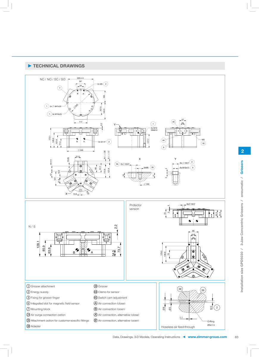
220
S17
81.1
127.
8
220±0.02
54
30°
105
145.
5
107.
5
117
240
77.510
7.6
129.
9172.
1
2.2
51.9
13.9
R32
13.9
57
51.912
1
68
N30
44±0
.02
117.
7
57
35
100
3xM6
1110
2x 10H7 6x 16h7
6x M12x1744
114.
9
13.8
5
B A 2x G1/4" 2
X
B` A`
2x M5
2x 8H7x25
3x M16x35
1
1
2
7
Y3x M12DIN912
145
44
6
M5
19
X
3535
Y3
3
63.685
.9128.
1
2.2
73.7
34.5AB
6x 16h743
70 64.3
62.3
70136.
8
179.
5
44.6
39
86
3938
M5
1.1
Ø5
Ø8
O-RingØ5x1.5
2
2
83
NC / NO / SC / SO
N / S
Protector version
Hoseless air feed-through
► TECHNICAL DRAWINGS
1 Gripper attachment
2 Energy supply
3 Fixing for gripper finger
6 Integrated slot for magnetic field sensor
7 Mounting block
bu Air purge connection option
dq Attachment option for customer-specific fittings
dt Adapter
du Gripper
ep Clamp for sensor
eq Switch cam adjustment
A Air connection (close)
B Air connection (open)
K Air connection, alternative (close)
L Air connection, alternative (open)
Inst
alla
tion
size
GPD
5030
/
3-Ja
w C
once
ntric
Grip
pers
/
pneu
mat
ic /
G
rippe
rs
Data, Drawings, 3-D Models, Operating Instructions ◄ www.zimmer-group.com

1
2
3
4
56
7
2
84
► INCLUDED IN DELIVERY
Centering Disc
030529
1
3-JAW CONCENTRIC GRIPPERSINSTALLATION SIZE GPD5030
Inst
alla
tion
size
GPD
5030
/
3-Ja
w C
once
ntric
Grip
pers
/
pneu
mat
ic /
G
rippe
rs
www.zimmer-group.com ► Data, Drawings, 3-D Models, Operating Instructions
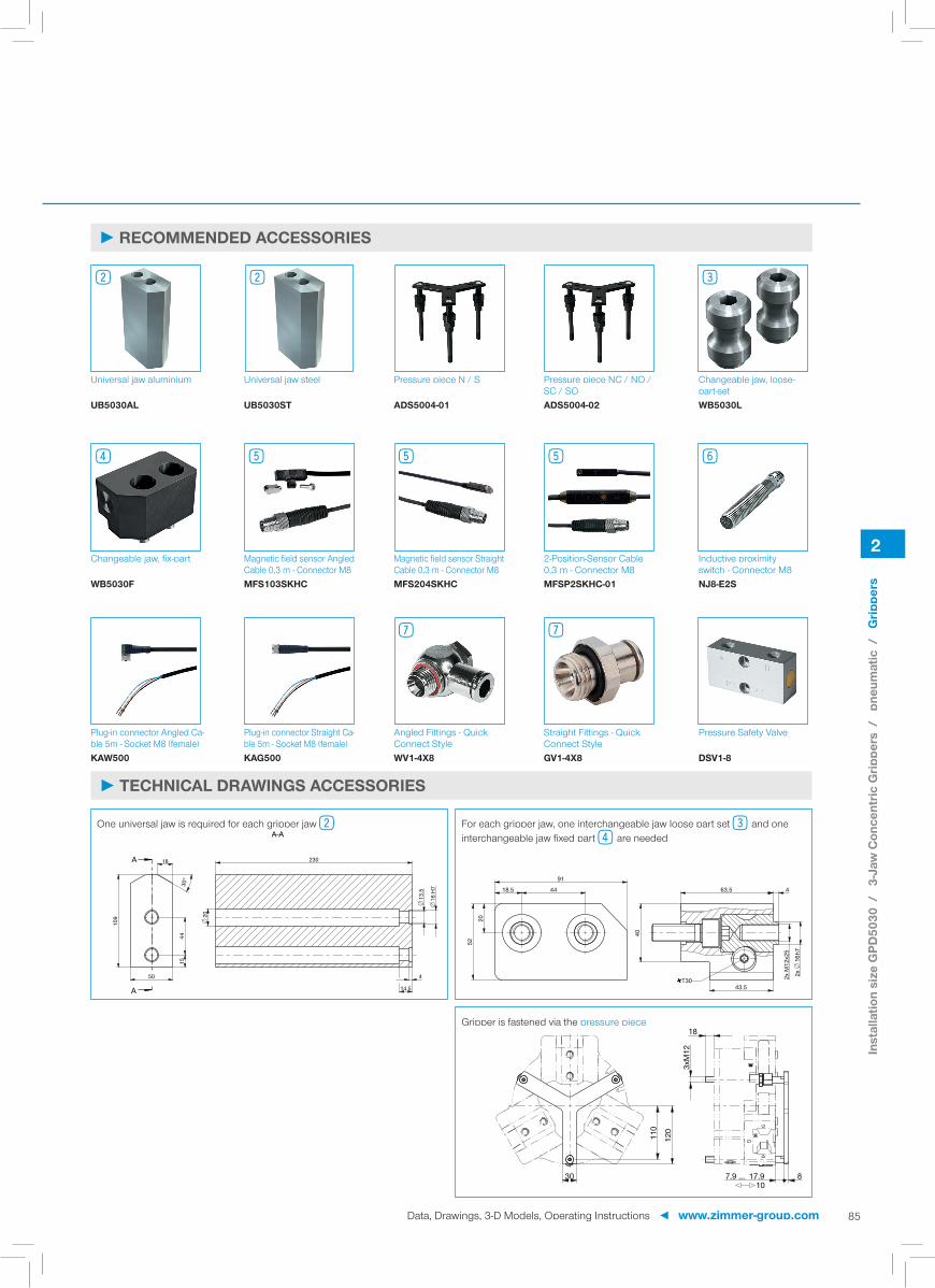
A
A
109
18
30°
1544
230
20
13.5
16 H
7
450
14.5
A-A
18.5
91
44
20
52
63.5 4
2x
16h7
2x M
12x2
5
43.5
40
T30
30 87.9 ... 17.910
3xM
12
18
120
110
2
85
► RECOMMENDED ACCESSORIES
Universal jaw aluminium Universal jaw steel Pressure piece N / S Pressure piece NC / NO / SC / SO
Changeable jaw, loose-part-set
UB5030AL UB5030ST ADS5004-01 ADS5004-02 WB5030L
Changeable jaw, fi x-part Magnetic fi eld sensor Angled Cable 0,3 m - Connector M8
Magnetic fi eld sensor Straight Cable 0,3 m - Connector M8
2-Position-Sensor Cable 0,3 m - Connector M8
Inductive proximity switch - Connector M8
WB5030F MFS103SKHC MFS204SKHC MFSP2SKHC-01 NJ8-E2S
Plug-in connector Angled Ca-ble 5m - Socket M8 (female)
Plug-in connector Straight Ca-ble 5m - Socket M8 (female)
Angled Fittings - Quick Connect Style
Straight Fittings - Quick Connect Style
Pressure Safety Valve
KAW500 KAG500 WV1-4X8 GV1-4X8 DSV1-8
2 2 3
4 5 5 5 6
7 7
One universal jaw is required for each gripper jaw 2 For each gripper jaw, one interchangeable jaw loose part set 3and one interchangeable jaw fi xed part 4are needed
Gripper is fastened via the pressure piece
► TECHNICAL DRAWINGS ACCESSORIES
Inst
alla
tion
size
GPD
5030
/
3-Ja
w C
once
ntric
Grip
pers
/
pneu
mat
ic /
G
rippe
rs
Data, Drawings, 3-D Models, Operating Instructions ◄ www.zimmer-group.com

3
86
► Our products love the challenge!Extreme conditions, all over the world—our tried and tested components and systems give you limitless possibilities: Find the best product for your specifi c use: www.zimmer-group.com
2-JAW PARALLEL GRIPPERSSERIES GEP5000
► PRODUCT ADVANTAGES
► THE BEST PRODUCT FOR YOUR APPLICATION
“ALL in ONE” ► Approximately the same gripping force as a compa-rable pneumatic gripper
► Mechanical self limitation in case of power drop
► Same connection hole patterns as a comparable pneumatic gripper
► Plug and play – single-cable solution, supports in-credibly easy control using I/O signals
► Integrated ACM control module - option of confi gur-ing gripping force, travel time and 3 switching points
► Protected from corrosion and sealed in accordance with IP64
► Brushless DC motor – up to 30 million cycles without maintenance
www.zimmer-group.com ► Data, Drawings, 3-D Models, Operating Instructions
Serie
s G
EP50
00 /
2-
Jaw
Par
alle
l Grip
pers
/
elec
tric
/
Grip
pers

5
6
18 3
4
7
2
3
87
Gripping force: arithmetic sum of the individual forces occuring at the jaws
Gripping direction: Movement toward the workpiece to be gripped
→|←: Gripping direction of external gripper
|←→|: Gripping direction of internal gripper
Travel time: Time required for the complete stroke movement of the gripper jaws
Control time: Response time of the gripping system
Work time: Time from signal input until the signal output message, including travel time
Mode: Travel time optimization by adapting to the gripping direction (N / NC / NO mode)
Repeatability: at end stops after 50/100 consecutive cycles
Cycle: Path that the gripper jaws travel for a complete opening and closing movement
Maintenance: recommended at 30 mil. cycles (please see the installation instructions, download from www.zimmer-group.com)
► BENEFITS IN DETAIL
1Positively driven wedge hook transmission - Supports to absorb high forces and moments - Synchronized gripper jaw movement
2Gripper jaw - DLC coated to protect against corrosion - Gripper fi ngers mounted using removable centring sleeves - Lubricated for life via incorporated lubrication slots
3Dual lip seal - Enables IP64 - Prevents grease from being squeezed out, increasing service life
4Steel Linear Guide - Steel in steel guide - Enables use of extremely long gripper fi ngers
5Mounting and positioning - Alternatively, on several sides for customized mounting - Pneumatic and electrical versions identical apart from height
6BLDC motor - Wear-resistant brushless DC motor
7Advanced control module - Integrated control module with single-cable solution - Gripping force, travel time and query programmable via the control panel on the housing
8Drive train - Combination of trapezoidal spindle and gear - Durable and robust
► TERMS
Data, Drawings, 3-D Models, Operating Instructions ◄ www.zimmer-group.com
Serie
s G
EP50
00 /
2-
Jaw
Par
alle
l Grip
pers
/
elec
tric
/
Grip
pers

3
88
► PRODUCT SPECIFICATIONS
► Gripping force diagram ► Forces and moments
400
800
5
200
600
0352515 45 55 65 75 85 95 105
[N]
[mm]
1000
Gripping force as a function finger length. Displays static forces and moments that can also have an effect, besides the gripping force.
Mx
My Mr
Fa
Mr [Nm] 43Mx [Nm] 70My [Nm] 46Fa [N] 1250
Stroke per jaw [mm] 6Control time [s] 0.035Weight per jaw max. [kg] 0.4Length of the gripper fi ngers max. [mm]* 100Repetition accuracy +/- [mm] 0.01Voltage [V] 24Current consumption max. [A] 5Operating temperature min. [°C] 5Operating temperature max. [°C] 50Protection to IEC 60529 IP64Weight [kg] 0.79
*Depending on speed level selected
► Technical DataOrder no. GEP5006N
Gripping force →|← min. / max. [N] 540 / 960Gripping force |←→| min. / max. [N] 540 / 960Travel time →|← min. / max. [s] 0,15 / 0,22Travel time |←→| min. / max. [s] 0,15 / 0,22
► Technical data - N modeOrder no. GEP5006N
Gripping force →|← min. / max. [N] 540 / 960Gripping force |←→| min. / max. [N] -Travel time →|← min. / max. [s] 0,15 / 0,22Travel time |←→| min. / max. [s] 0,13
► Technical data - NC modeOrder no. GEP5006N
Gripping force →|← min. / max. [N] -Gripping force |←→| min. / max. [N] 540 / 960Travel time →|← min. / max. [s] 0,13Travel time |←→| min. / max. [s] 0,15 / 0,22
► Technical data - NO modeOrder no. GEP5006N
2-JAW PARALLEL GRIPPERSINSTALLATION SIZE GEP5006
► TECHNICAL DATA - BASIC VERSION
► TECHNICAL DATA - MODES
Inst
alla
tion
size
GEP
5006
/
2-Ja
w P
aral
lel G
rippe
rs /
el
ectr
ic /
G
rippe
rs
www.zimmer-group.com ► Data, Drawings, 3-D Models, Operating Instructions

6
42±0.02 ø8H7
27
±0
.02
ø8H
7
76
13
100
15.3 42
8078.5
1.5
13
80
42±0.02
78.5
±0.0
2
17.5
11
24
27
36
28.513±0.02
21.5
16.3
2x 8h7
2.5
4x 6h7
4x M4x62.5
2.5
14
4.5
2.5
2x 2.5H74xM2.5
2228
20
M5 19
X
4x M5x10
2x 8H7x2.5
1
1
1
1
2
Y
2x M4DIN912*
4x M4DIN912*
M519 2x 8H7x2.5
1
3
3
Y
3535
X
3
89
► TECHNICAL DRAWINGS
1 Gripper attachment
2 Energy supply
3 Fixing for gripper finger
bu Air purge connection option
dq Attachment option for customer-specific fittings
Inst
alla
tion
size
GEP
5006
/
2-Ja
w P
aral
lel G
rippe
rs /
el
ectr
ic /
G
rippe
rs
Data, Drawings, 3-D Models, Operating Instructions ◄ www.zimmer-group.com

1
2
3
4
5
6
3
90
► INCLUDED IN DELIVERY
Centering Disc Centering Disc
024230 024231
1 2
2-JAW PARALLEL GRIPPERSINSTALLATION SIZE GEP5006
Inst
alla
tion
size
GEP
5006
/
2-Ja
w P
aral
lel G
rippe
rs /
el
ectr
ic /
G
rippe
rs
www.zimmer-group.com ► Data, Drawings, 3-D Models, Operating Instructions

A
A
33
8
30°
513
65
8
4.5
6 H
7
2.520
4.5
A-A
31.5
136.5
7
19
22 2.5
12.5
15
2x
6h7
2x M
4x11
T15
3
91
► RECOMMENDED ACCESSORIES
Universal jaw aluminium Universal jaw steel Changeable jaw, loose-part-set
Changeable jaw, fi x-part Plug-in Connector Angled Cable 10 m - Female M12
UB5006AL UB5006ST WB5006L WB5006F KAW1000B8
Plug-in Connector Straight Cable 10 m - Female M12KAG1000B8
3 3 4 5 6
6
One universal jaw is required for each gripper jaw 3 For each gripper jaw, one interchangeable jaw loose part set 4and one interchangeable jaw fi xed part 5are needed
► TECHNICAL DRAWINGS ACCESSORIES
Inst
alla
tion
size
GEP
5006
/
2-Ja
w P
aral
lel G
rippe
rs /
el
ectr
ic /
G
rippe
rs
Data, Drawings, 3-D Models, Operating Instructions ◄ www.zimmer-group.com

3
92
► PRODUCT SPECIFICATIONS
► Gripping force diagram ► Forces and moments
600
1200
300
900
1500
0
[N]
50
352515 45 55 65 75 85 95 105 115 125[mm]
Gripping force as a function finger length. Displays static forces and moments that can also have an effect, besides the gripping force.
Mx
My Mr
Fa
Mr [Nm] 60Mx [Nm] 105My [Nm] 65Fa [N] 1900
Stroke per jaw [mm] 8Control time [s] 0.035Weight per jaw max. [kg] 0.7Length of the gripper fi ngers max. [mm]* 125Repetition accuracy +/- [mm] 0.01Voltage [V] 24Current consumption max. [A] 5Operating temperature min. [°C] 5Operating temperature max. [°C] 50Protection to IEC 60529 IP64Weight [kg] 1.16
*Depending on speed level selected
► Technical DataOrder no. GEP5008N
Gripping force →|← min. / max. [N] 800 / 1450Gripping force |←→| min. / max. [N] 800 / 1450Travel time →|← min. / max. [s] 0,18 / 0,29Travel time |←→| min. / max. [s] 0,18 / 0,29
► Technical data - N modeOrder no. GEP5008N
Gripping force →|← min. / max. [N] 800 / 1450Gripping force |←→| min. / max. [N] -Travel time →|← min. / max. [s] 0,18 / 0,29Travel time |←→| min. / max. [s] 0,15
► Technical data - NC modeOrder no. GEP5008N
Gripping force →|← min. / max. [N] -Gripping force |←→| min. / max. [N] 800 / 1450Travel time →|← min. / max. [s] 0,15Travel time |←→| min. / max. [s] 0,18 / 0,29
► Technical data - NO modeOrder no. GEP5008N
2-JAW PARALLEL GRIPPERSINSTALLATION SIZE GEP5008
► TECHNICAL DATA - BASIC VERSION
► TECHNICAL DATA - MODES
Inst
alla
tion
size
GEP
5008
/
2-Ja
w P
aral
lel G
rippe
rs /
el
ectr
ic /
G
rippe
rs
www.zimmer-group.com ► Data, Drawings, 3-D Models, Operating Instructions

8
52±0.02 ø8H7
32
±0
.02
ø8H
7
21
13
31
42
32
13
96
1.5
104
75
15.5 52
80
26
16±0.02 37
16.3
2x 8h7
2.5
4x 8h7
4x M5x8
2.5
2.5
80
75±0
.02
52±0.02
13
194.5
4xM2.52x 3H7
3
2734.5
26.5
M5 194x M4DIN912*
2x M5DIN912*
1
1
Y
2
M5 2x 8H7x2.519
1
4x M5x14.5
2x 8H7x2.5
1
1
XY
3
335
35X
3
93
► TECHNICAL DRAWINGS
1 Gripper attachment
2 Energy supply
3 Fixing for gripper finger
bu Air purge connection option
dq Attachment option for customer-specific fittings
Inst
alla
tion
size
GEP
5008
/
2-Ja
w P
aral
lel G
rippe
rs /
el
ectr
ic /
G
rippe
rs
Data, Drawings, 3-D Models, Operating Instructions ◄ www.zimmer-group.com

1
2
3
4
5
6
3
94
► INCLUDED IN DELIVERY
Centering Disc
024231
12
2-JAW PARALLEL GRIPPERSINSTALLATION SIZE GEP5008
Inst
alla
tion
size
GEP
5008
/
2-Ja
w P
aral
lel G
rippe
rs /
el
ectr
ic /
G
rippe
rs
www.zimmer-group.com ► Data, Drawings, 3-D Models, Operating Instructions

A
A
25
616
41
30°
11.5
10
80
2.5
4.5
5.5
8 H
7
A-A
38
8.5 16
8.5
23.5 16
.5
28
2x M
5x13
2x
8h7
17
2.5
T15
3
95
► RECOMMENDED ACCESSORIES
Universal jaw aluminium Universal jaw steel Changeable jaw, loose-part-set
Changeable jaw, fi x-part Plug-in Connector Angled Cable 10 m - Female M12
UB5008AL UB5008ST WB5008L WB5008F KAW1000B8
Plug-in Connector Straight Cable 10 m - Female M12KAG1000B8
3 3 4 5 6
6
One universal jaw is required for each gripper jaw 3 For each gripper jaw, one interchangeable jaw loose part set 4and one interchangeable jaw fi xed part 5are needed
► TECHNICAL DRAWINGS ACCESSORIES
Inst
alla
tion
size
GEP
5008
/
2-Ja
w P
aral
lel G
rippe
rs /
el
ectr
ic /
G
rippe
rs
Data, Drawings, 3-D Models, Operating Instructions ◄ www.zimmer-group.com

3
96
► PRODUCT SPECIFICATIONS
► Gripping force diagram ► Forces and moments
800
1600
400
1200
2000
0
[N]
5 352515 45 55 65 75 85 95 105 115 125 135 145 155[mm]
Gripping force as a function finger length. Displays static forces and moments that can also have an effect, besides the gripping force.
Mx
My Mr
Fa
Mr [Nm] 75Mx [Nm] 125My [Nm] 95Fa [N] 2700
Stroke per jaw [mm] 10Control time [s] 0.035Weight per jaw max. [kg] 1.3Length of the gripper fi ngers max. [mm]* 160Repetition accuracy +/- [mm] 0.01Voltage [V] 24Current consumption max. [A] 5Operating temperature min. [°C] 5Operating temperature max. [°C] 50Protection to IEC 60529 IP64Weight [kg] 1.66
*Depending on speed level selected
► Technical DataOrder no. GEP5010N
Gripping force →|← min. / max. [N] 1200 / 1900Gripping force |←→| min. / max. [N] 1200 / 1900Travel time →|← min. / max. [s] 0,21 / 0,32Travel time |←→| min. / max. [s] 0,21 / 0,32
► Technical data - N modeOrder no. GEP5010N
Gripping force →|← min. / max. [N] 1200 / 1900Gripping force |←→| min. / max. [N] -Travel time →|← min. / max. [s] 0,21 / 0,32Travel time |←→| min. / max. [s] 0,16
► Technical data - NC modeOrder no. GEP5010N
Gripping force →|← min. / max. [N] -Gripping force |←→| min. / max. [N] 1200 / 1900Travel time →|← min. / max. [s] 0,16Travel time |←→| min. / max. [s] 0,21 / 0,32
► Technical data - NO modeOrder no. GEP5010N
2-JAW PARALLEL GRIPPERSINSTALLATION SIZE GEP5010
► TECHNICAL DATA - BASIC VERSION
► TECHNICAL DATA - MODES
Inst
alla
tion
size
GEP
5010
/
2-Ja
w P
aral
lel G
rippe
rs /
el
ectr
ic /
G
rippe
rs
www.zimmer-group.com ► Data, Drawings, 3-D Models, Operating Instructions

10
66±0.02 ø10H7
38
±
0.02
ø10
H7
33.5
37.5
50
25
16
120
1379
.8
76
106
1.7
6615.5
32.8
4720±0.02
16.3
2x 10h7
3
4x 10h7
4x M6x9
33
79.8
13
66±0.02
76±0
.02
3139
32.5
4xM32x 4H7
5
24.5
4
M5 194x M5DIN912*
2x M6DIN912*
1
1
4x M6x15
2x 10H7x3
1
1
X
Y 2x 10H7x3M5
1
19
Y3
3
X
3535
3
97
► TECHNICAL DRAWINGS
1 Gripper attachment
2 Energy supply
3 Fixing for gripper finger
bu Air purge connection option
dq Attachment option for customer-specific fittings
Inst
alla
tion
size
GEP
5010
/
2-Ja
w P
aral
lel G
rippe
rs /
el
ectr
ic /
G
rippe
rs
Data, Drawings, 3-D Models, Operating Instructions ◄ www.zimmer-group.com

1
2
3
4
5
6
3
98
► INCLUDED IN DELIVERY
Centering Disc
018187
12
2-JAW PARALLEL GRIPPERSINSTALLATION SIZE GEP5010
Inst
alla
tion
size
GEP
5010
/
2-Ja
w P
aral
lel G
rippe
rs /
el
ectr
ic /
G
rippe
rs
www.zimmer-group.com ► Data, Drawings, 3-D Models, Operating Instructions

A
A
51
12.5
30°
720
30
11
100
3
5
6.5 10
H7
A-A
45
209.5
10.5
28
19
35 3
2x
10h7
2x M
6x15
22T15
3
99
► RECOMMENDED ACCESSORIES
Universal jaw aluminium Universal jaw steel Changeable jaw, loose-part-set
Changeable jaw, fi x-part Plug-in Connector Angled Cable 10 m - Female M12
UB5010AL UB5010ST WB5010L WB5010F KAW1000B8
Plug-in Connector Straight Cable 10 m - Female M12KAG1000B8
3 3 4 5 6
6
One universal jaw is required for each gripper jaw 3 For each gripper jaw, one interchangeable jaw loose part set 4and one interchangeable jaw fi xed part 5are needed
► TECHNICAL DRAWINGS ACCESSORIES
Inst
alla
tion
size
GEP
5010
/
2-Ja
w P
aral
lel G
rippe
rs /
el
ectr
ic /
G
rippe
rs
Data, Drawings, 3-D Models, Operating Instructions ◄ www.zimmer-group.com

4
100
► Our products love the challenge!Extreme conditions, all over the world—our tried and tested components and systems give you limitless possibilities: Find the best product for your specifi c use: www.zimmer-group.com
3-JAW CONCENTRIC GRIPPERSSERIES GED5000
► PRODUCT ADVANTAGES
► THE BEST PRODUCT FOR YOUR APPLICATION
“ALL in ONE” ► Approximately the same gripping force as a compa-rable pneumatic gripper
► Mechanical self limitation in case of power drop
► Same connection hole patterns as a comparable pneumatic gripper
► Plug and play – single-cable solution, supports in-credibly easy control using I/O signals
► Integrated ACM control module - option of confi gur-ing gripping force, travel time and 3 switching points
► Protected from corrosion and sealed in accordance with IP64
► Brushless DC motor – up to 30 million cycles without maintenance
www.zimmer-group.com ► Data, Drawings, 3-D Models, Operating Instructions
Serie
s G
ED50
00 /
3-
Jaw
Con
cent
ric G
rippe
rs /
el
ectr
ic /
G
rippe
rs

67
1 2
3
4
5
8
4
101
Gripping force: arithmetic sum of the individual forces occuring at the jaws
Gripping direction: Movement toward the workpiece to be gripped
→|←: Gripping direction of external gripper
|←→|: Gripping direction of internal gripper
Travel time: Time required for the complete stroke movement of the gripper jaws
Control time: Response time of the gripping system
Work time: Time from signal input until the signal output message, including travel time
Mode: Travel time optimization by adapting to the gripping direction (N / NC / NO mode)
Repeatability: at end stops after 50/100 consecutive cycles
Cycle: Path that the gripper jaws travel for a complete opening and closing movement
Maintenance: recommended at 30 mil. cycles (please see the installation instructions, download from www.zimmer-group.com)
► BENEFITS IN DETAIL
1Positively driven wedge hook transmission - high forces and moments capacity - Synchronized gripper jaw movement
2Gripper jaw - DLC coated to protect against corrosion - Gripper fi ngers mounted using removable centring sleeves - Lubricated for life via incorporated lubrication slots
3Dual lip seal - Enables IP64 - Prevents grease from being squeezed out, increasing service life
4Steel Linear Guide - Steel in steel guide - Enables use of extremely long gripper fi ngers
5Mounting and positioning - Alternatively, on several sides for customized mounting - Pneumatic and electrical versions identical apart from height
6BLDC motor - Wear-resistant brushless DC motor
7Advanced control module - Integrated control module with single-cable solution - Gripping force, travel time and query programmable via the control panel on the housing
8Drive train - Combination of trapezoidal spindle and gear - Durable and robust
► TERMS
Data, Drawings, 3-D Models, Operating Instructions ◄ www.zimmer-group.com
Serie
s G
ED50
00 /
3-
Jaw
Con
cent
ric G
rippe
rs /
el
ectr
ic /
G
rippe
rs

4
102
► PRODUCT SPECIFICATIONS
► Gripping force diagram ► Forces and moments
400
800
5
200
600
0352515 45 55 65 75 85 95 105
[N]1000
[mm]
Gripping force as a function finger length. Displays static forces and moments that can also have an effect, besides the gripping force.
Mx
My Mr
Fa
Mr [Nm] 43Mx [Nm] 70My [Nm] 46Fa [N] 1250
Stroke per jaw [mm] 6Control time [s] 0.035Weight per jaw max. [kg] 0.4Length of the gripper fi ngers max. [mm]* 100Repetition accuracy +/- [mm] 0.01Voltage [V] 24Current consumption max. [A] 5Operating temperature min. [°C] 5Operating temperature max. [°C] 50Protection to IEC 60529 IP64Weight [kg] 1.09
*Depending on speed level selected
► Technical DataOrder no. GED5006N
Gripping force →|← min. / max. [N] 540 / 960Gripping force |←→| min. / max. [N] 540 / 960Travel time →|← min. / max. [s] 0,15 / 0,22Travel time |←→| min. / max. [s] 0,15 / 0,22
► Technical data - N modeOrder no. GED5006N
Gripping force →|← min. / max. [N] 540 / 960Gripping force |←→| min. / max. [N] -Travel time →|← min. / max. [s] 0,15 / 0,22Travel time |←→| min. / max. [s] 0,13
► Technical data - NC modeOrder no. GED5006N
Gripping force →|← min. / max. [N] -Gripping force |←→| min. / max. [N] 540 / 960Travel time →|← min. / max. [s] 0,13Travel time |←→| min. / max. [s] 0,15 / 0,22
► Technical data - NO modeOrder no. GED5006N
3-JAW CONCENTRIC GRIPPERSINSTALLATION SIZE GED5006
► TECHNICAL DATA - BASIC VERSION
► TECHNICAL DATA - MODES
Inst
alla
tion
size
GED
5006
/
3-Ja
w C
once
ntric
Grip
pers
/
elec
tric
/
Grip
pers
www.zimmer-group.com ► Data, Drawings, 3-D Models, Operating Instructions
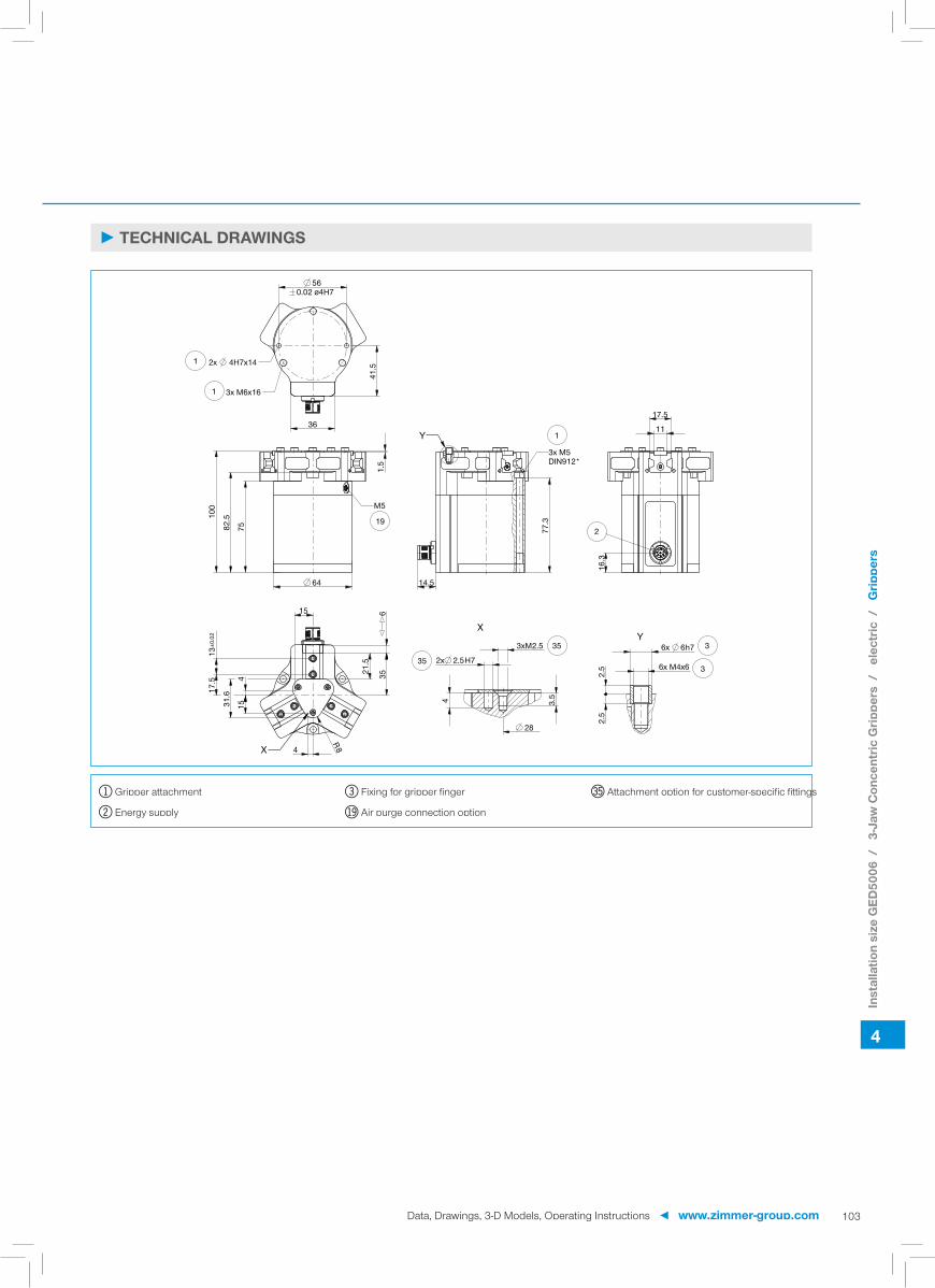
6
560.02 ø4H7
41.5
36
100
1.5
82.5
75
64
17.5
13±0
.02
21.5
16.3
11
17.5
77.3
6x 6h7
6x M4x6
2.5
2.5
2x 2.5H7
3xM2.5
4 3.5
28
415
4
15R8
31.6
14.5
35
2
3x M5DIN912*
1Y
M5
19
3x M6x16
2x 4H7x141
1
X
3
3Y
35
35
X
4
103
► TECHNICAL DRAWINGS
1 Gripper attachment
2 Energy supply
3 Fixing for gripper finger
bu Air purge connection option
dq Attachment option for customer-specific fittings
Inst
alla
tion
size
GED
5006
/
3-Ja
w C
once
ntric
Grip
pers
/
elec
tric
/
Grip
pers
Data, Drawings, 3-D Models, Operating Instructions ◄ www.zimmer-group.com

1
2
3
4
5
4
104
► INCLUDED IN DELIVERY
Centering Disc
024230
1
3-JAW CONCENTRIC GRIPPERSINSTALLATION SIZE GED5006
Inst
alla
tion
size
GED
5006
/
3-Ja
w C
once
ntric
Grip
pers
/
elec
tric
/
Grip
pers
www.zimmer-group.com ► Data, Drawings, 3-D Models, Operating Instructions

A
A
33
8
30°
513
65
8
4.5
6 H
7
2.520
4.5
A-A
31.5
136.5
7
19
22 2.5
12.5
15
2x
6h7
2x M
4x11
T15
28 32
12
3xM
5
7.5
4.1
0 ... 44
4
4
105
► RECOMMENDED ACCESSORIES
Universal jaw aluminium Universal jaw steel Pressure piece Changeable jaw, loose-part-set
Changeable jaw, fi x-part
UB5006AL UB5006ST ADS5006-05 WB5006L WB5006F
Plug-in Connector Angled Cable 10 m - Female M12
Plug-in Connector Straight Cable 10 m - Female M12
KAW1000B8 KAG1000B8
2 2 3 4
5 5
One universal jaw is required for each gripper jaw 2 For each gripper jaw, one interchangeable jaw loose part set 3and one interchangeable jaw fi xed part 4are needed
Gripper is fastened via the pressure piece
► TECHNICAL DRAWINGS ACCESSORIES
Inst
alla
tion
size
GED
5006
/
3-Ja
w C
once
ntric
Grip
pers
/
elec
tric
/
Grip
pers
Data, Drawings, 3-D Models, Operating Instructions ◄ www.zimmer-group.com

4
106
► PRODUCT SPECIFICATIONS
► Gripping force diagram ► Forces and moments
600
1200
300
900
1500
0
[N]
50
352515 45 55 65 75 85 95 105 115 125[mm]
Gripping force as a function finger length. Displays static forces and moments that can also have an effect, besides the gripping force.
Mx
My Mr
Fa
Mr [Nm] 60Mx [Nm] 105My [Nm] 65Fa [N] 1900
Stroke per jaw [mm] 8Control time [s] 0.035Weight per jaw max. [kg] 0.7Length of the gripper fi ngers max. [mm]* 125Repetition accuracy +/- [mm] 0.01Voltage [V] 24Current consumption max. [A] 5Operating temperature min. [°C] 5Operating temperature max. [°C] 50Protection to IEC 60529 IP64Weight [kg] 1.66
*Depending on speed level selected
► Technical DataOrder no. GED5008N
Gripping force →|← min. / max. [N] 800 / 1450Gripping force |←→| min. / max. [N] 800 / 1450Travel time →|← min. / max. [s] 0,18 / 0,29Travel time |←→| min. / max. [s] 0,18 / 0,29
► Technical data - N modeOrder no. GED5008N
Gripping force →|← min. / max. [N] 800 / 1450Gripping force |←→| min. / max. [N] -Travel time →|← min. / max. [s] 0,18 / 0,29Travel time |←→| min. / max. [s] 0,15
► Technical data - NC modeOrder no. GED5008N
Gripping force →|← min. / max. [N] -Gripping force |←→| min. / max. [N] 800 / 1450Travel time →|← min. / max. [s] 0,15Travel time |←→| min. / max. [s] 0,18 / 0,29
► Technical data - NO modeOrder no. GED5008N
3-JAW CONCENTRIC GRIPPERSINSTALLATION SIZE GED5008
► TECHNICAL DATA - BASIC VERSION
► TECHNICAL DATA - MODES
Inst
alla
tion
size
GED
5008
/
3-Ja
w C
once
ntric
Grip
pers
/
elec
tric
/
Grip
pers
www.zimmer-group.com ► Data, Drawings, 3-D Models, Operating Instructions

8
700.02 ø5H7
51.5
42
80
7585
104
1.5
2216
±0.0
2
26
78.8
16.3
13
21
6x 8h7
6x M5x8
2.5
2.5
5.1
19.1
5.1
19.1
39.5
R8.5
3xM2.5
3.54
2x 3H7
36
14.5
43
M5
19
X
2x 5H7x14
3x M8x19
1
1
3x M6DIN912*
1Y
2
3
3YX
35
35
4
107
► TECHNICAL DRAWINGS
1 Gripper attachment
2 Energy supply
3 Fixing for gripper finger
bu Air purge connection option
dq Attachment option for customer-specific fittings
Inst
alla
tion
size
GED
5008
/
3-Ja
w C
once
ntric
Grip
pers
/
elec
tric
/
Grip
pers
Data, Drawings, 3-D Models, Operating Instructions ◄ www.zimmer-group.com
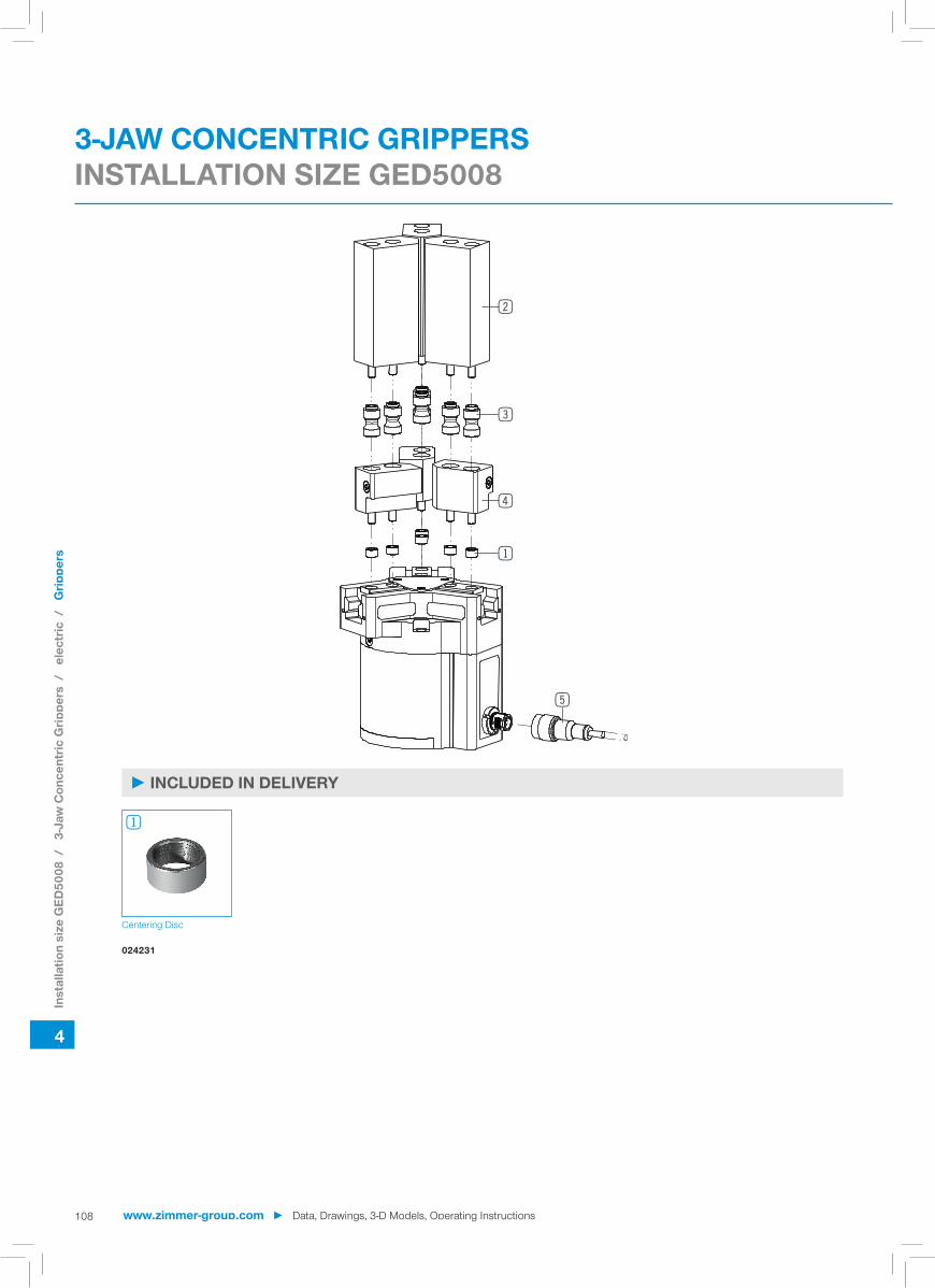
1
2
3
4
5
4
108
► INCLUDED IN DELIVERY
Centering Disc
024231
1
3-JAW CONCENTRIC GRIPPERSINSTALLATION SIZE GED5008
Inst
alla
tion
size
GED
5008
/
3-Ja
w C
once
ntric
Grip
pers
/
elec
tric
/
Grip
pers
www.zimmer-group.com ► Data, Drawings, 3-D Models, Operating Instructions

A
A
25
616
41
30°
11.5
10
80
2.5
4.5
5.5
8 H
7
A-A
38
8.5 16
8.5
23.5 16
.5
28
2x M
5x13
2x
8h7
17
2.5
T15
13
4035
9
3xM
6
2.1
3.2 ... 8.25
4
4
109
► RECOMMENDED ACCESSORIES
Universal jaw aluminium Universal jaw steel Pressure piece Changeable jaw, loose-part-set
Changeable jaw, fi x-part
UB5008AL UB5008ST ADS5006-05 WB5008L WB5008F
Plug-in Connector Angled Cable 10 m - Female M12
Plug-in Connector Straight Cable 10 m - Female M12
KAW1000B8 KAG1000B8
2 2 3 4
5 5
One universal jaw is required for each gripper jaw 2 For each gripper jaw, one interchangeable jaw loose part set 3and one interchangeable jaw fi xed part 4are needed
Gripper is fastened via the pressure piece
► TECHNICAL DRAWINGS ACCESSORIES
Inst
alla
tion
size
GED
5008
/
3-Ja
w C
once
ntric
Grip
pers
/
elec
tric
/
Grip
pers
Data, Drawings, 3-D Models, Operating Instructions ◄ www.zimmer-group.com

4
110
► PRODUCT SPECIFICATIONS
► Gripping force diagram ► Forces and moments
800
1600
400
1200
2000
0
[N]
5 352515 45 55 65 75 85 95 105 115 125 135 145 155[mm]
Speed level 5
Speed level 4
Speed level 3
Speed level 2Speed level 1
Gripping force as a function finger length. Displays static forces and moments that can also have an effect, besides the gripping force.
Mx
My Mr
Fa
Mr [Nm] 75Mx [Nm] 125My [Nm] 95Fa [N] 2700
Stroke per jaw [mm] 10Control time [s] 0.035Weight per jaw max. [kg] 1.3Length of the gripper fi ngers max. [mm]* 160Repetition accuracy +/- [mm] 0.01Voltage [V] 24Current consumption max. [A] 5Operating temperature min. [°C] 5Operating temperature max. [°C] 50Protection to IEC 60529 IP64Weight [kg] 2.33
*Depending on speed level selected
► Technical DataOrder no. GED5010N
Gripping force →|← min. / max. [N] 1200 / 1900Gripping force |←→| min. / max. [N] 1200 / 1900Travel time →|← min. / max. [s] 0,21 / 0,32Travel time |←→| min. / max. [s] 0,21 / 0,32
► Technical data - N modeOrder no. GED5010N
Gripping force →|← min. / max. [N] 1200 / 1900Gripping force |←→| min. / max. [N] -Travel time →|← min. / max. [s] 0,21 / 0,32Travel time |←→| min. / max. [s] 0,16
► Technical data - NC modeOrder no. GED5010N
Gripping force →|← min. / max. [N] -Gripping force |←→| min. / max. [N] 1200 / 1900Travel time →|← min. / max. [s] 0,16Travel time |←→| min. / max. [s] 0,21 / 0,32
► Technical data - NO modeOrder no. GED5010N
3-JAW CONCENTRIC GRIPPERSINSTALLATION SIZE GED5010
► TECHNICAL DATA - BASIC VERSION
► TECHNICAL DATA - MODES
Inst
alla
tion
size
GED
5010
/
3-Ja
w C
once
ntric
Grip
pers
/
elec
tric
/
Grip
pers
www.zimmer-group.com ► Data, Drawings, 3-D Models, Operating Instructions

10
900.02 ø5H7
64
50
105.
5
7585.3
100
1.7
27.5
20±0
.02
32.8
79.1
25
16
6x 10h7
6x M6x9
3348
.3
5.9
21.9
5.9
R1221.9
40
2x 4H73M3
5 59.88 16
.3
53.5
M5
19
X
2x 5H7x14
3x M8x191
1
3x M6DIN912*
1Y
2
Y
3
335
35
X
4
111
► TECHNICAL DRAWINGS
1 Gripper attachment
2 Energy supply
3 Fixing for gripper finger
bu Air purge connection option
dq Attachment option for customer-specific fittings
Inst
alla
tion
size
GED
5010
/
3-Ja
w C
once
ntric
Grip
pers
/
elec
tric
/
Grip
pers
Data, Drawings, 3-D Models, Operating Instructions ◄ www.zimmer-group.com

1
2
4
3
5
4
112
► INCLUDED IN DELIVERY
Centering Disc
018187
1
3-JAW CONCENTRIC GRIPPERSINSTALLATION SIZE GED5010
Inst
alla
tion
size
GED
5010
/
3-Ja
w C
once
ntric
Grip
pers
/
elec
tric
/
Grip
pers
www.zimmer-group.com ► Data, Drawings, 3-D Models, Operating Instructions

A
A
51
12.5
30°
720
30
11
100
3
5
6.5 10
H7
A-A
45
209.5
10.5
28
19
35 3
2x
10h7
2x M
6x15
22T15
45 50
15
3xM
6
9
4.8 ... 9.85
4
4
113
► RECOMMENDED ACCESSORIES
Universal jaw aluminium Universal jaw steel Pressure piece Changeable jaw, loose-part-set
Changeable jaw, fi x-part
UB5010AL UB5010ST ADS5006-05 WB5010L WB5010F
Plug-in Connector Angled Cable 10 m - Female M12
Plug-in Connector Straight Cable 10 m - Female M12
KAW1000B8 KAG1000B8
2 2 3 4
5 5
One universal jaw is required for each gripper jaw 2 For each gripper jaw, one interchangeable jaw loose part set 3and one interchangeable jaw fi xed part 4are needed
Gripper is fastened via the pressure piece
► TECHNICAL DRAWINGS ACCESSORIES
Inst
alla
tion
size
GED
5010
/
3-Ja
w C
once
ntric
Grip
pers
/
elec
tric
/
Grip
pers
Data, Drawings, 3-D Models, Operating Instructions ◄ www.zimmer-group.com

114
CHECKLIST GRIPPER
Self Locking
Gripping type
Chemical substances / If yes, which
Gripping inward
Frictional fit
Prism angle
Temperature
Gripping force
Not required When closing When opening Pressure safety valve
Coefficient of friction Axis acceleration
Form fit
Gripping outward
Clean / Dry Small amount of swarfCoolant overspray
Large amount of swarf Coolant under pressure of grinding agents
kg gN
°
or Workpiece weight
m/s²
Required force
°C Cycles per minute
Volts
Drive
Required stroke
Gripper finger length
Ambient conditions
Pneumatic
Per jaw
Gripper top edge to force application point
Operating pressure
Electric
bar
mm
mm
mmor
Hydraulic
Voltage
Total stroke
Customer number
Company
Contact Mr. Mrs.
Request
Order
Parallel gripper
Other / If yes, which type
Desired date
Three-jaw gripper
Req. No.
Ord No.
Angular gripper
Telephone number
Fax number
www.zimmer-group.com

115
Pressure safety valve
Notes/comments
Pneumatic fittings / If yes, which
Editor/Date
Sketch 3D model Other
Straight
Angled
Flow control valve
Desired accessories
Desired accessories
Inductive sensor
Separate cable / If yes, how long
Magnetic field sensor
Straight fitting
Angled fitting
With cable
m
Pluggable
www.zimmer-group.com

116
USAGE NOTEGENERAL
The contents of this catalog are not legally binding and are intended solely for informational purposes. Any final agreement will be in the form of a written order confirmation from ZIMMER GMBH, which occurs only subject to the respective current General Terms and Conditions of Sale and Delivery of ZIMMER GMBH. These can be found online at www.zimmer-group.com. All of the products listed in this catalog are designed for their intended use, e.g. machines for automation. The recognized technical regulations for safety and professional work must be followed for use and installation. Furthermore, the respective laws, guidelines from TÜV, guidelines from the respective trade association and VDE stipulations shall apply. The technical data listed in this catalog must be observed by the user. The conditions of use may not fall below or exceed the specified data. If information is missing, it cannot be assumed that there are no upper or lower limits or no limitations for specific use cases. Consultation is required in these cases. Disposal is not included in the price, which would have to be taken into account accordingly in the event of return to or dis-posal by ZIMMER GMBH.
TECHNICAL DATA AND FIGURESThe technical data and figures have been compiled with great care and to the best of our knowledge. We cannot guarantee that the information is up to date, correct or complete. The specifications and information — such as figures, drawings, descriptions, dimensions, weights, materials, technical and other performance data and the described products and services — contained in general product descriptions, ZIMMER GMBH catalogs, brochures and price lists in any form are subject to change and may be modified or updated at any time without prior notification. They are binding only to the extent expressly specified in a contract or order confirmation. Slight de-viations from such descriptive product information shall be considered approved and shall not affect fulfillment of agreements insofar as they are reasonable for the customer.
LIABILITYProducts from Zimmer Group are subject to the German Product Liability Act. This catalog does not contain any guarantees, assurances of quality or procurement agreements for the products it depicts, neither expressly nor implied, including for the availability of products. Advertising statements relating to quality features, properties or applications for the products are not legally binding. To the extent permitted by law, ZIMMER GMBH is exempt from any liability for direct or indirect damage, subsequent damage and requests of any kind or on any legal basis resulting from the use of information contained in this catalogue.
TRADEMARK, COPYRIGHT AND REPRODUCTIONThe depiction of commercial property rights in this catalog — such as brands, logos, registered trademarks or patents — does not include the granting of licenses or use rights. Their use is not permitted without the expressed written agreement of ZIM-MER GMBH. All contents of this catalog are the intellectual property of ZIMMER GMBH. For the purposes of copyright, any unlawful use of intellectual property, including excerpts, is prohibited. Reprinting, copying or translating (including in the form of excerpts) are permitted only with the prior written consent of ZIMMER GMBH.
STANDARDSZimmer Group has a quality management system certified in accordance with ISO 9001:2008. Zimmer Group has an environ-mental management system certified in accordance with ISO 14001:2004.
www.zimmer-group.com

117
USAGE NOTEINDIVIDUAL
DECLARATION OF INCORPORATION IN TERMS OF THE EC DIRECTIVE 2006/42/EC ON MACHINERY (AN-NEX II 1 B)We hereby declare that our elements meet the following basic requirements of the Machinery Directive 2006/42/EC as an incomplete machine No.1.1.2., No.1.1.3., No.1.1.5., No.1.3.2, No. 1.3.4, No. 1.3.7, No.1.5.3, No.1.5.4, No.1.5.8., No.1.6.4, No.1.7.1, No.1.7.3, No.1.7.4. We also declare that the specific technical documents were produced in accordance with Annex VII Part B of this Directive. We undertake to provide the market supervisory bodies with electronic versions of the incomplete machine‘s special docu-ments via our documentation department should they have reason to request them. The incomplete machine may only be commissioned if the machine or system in which the incomplete machine is to be installed has been determined to satisfy the conditions of the Machinery Directive 2006/42/EC and the EC Declaration of Conformity has been produced in accordance with Annex II A.
www.zimmer-group.com

118 www.zimmer-group.com ► Data, Drawings, 3-D Models, Operating Instructions