wlan multiband carpet fractal geometrie antenna … multiband carpet fractal... · international...
TRANSCRIPT

International Journal of Electronics, Communication & Soft Computing Science and Engineering ISSN: 2277-9477, Volume 3, Issue 6
23
WLAN Multiband Carpet Fractal Geometrie Antenna
for 5 to 9 Ghz
Alok Dwivedi
Sumit Dubey
Anil Mishra
Abstract—Modern communication system require
antenna with wider bandwidth, smaller dimension, high
gain and high efficiency. Various antennas for wide
band operation have been studied for communication
and radar system. The use of fractal geometry in
designing antenna has been a recent topic of interest.
Fractal antenna is preferred due to small size, light
weight and easy installation. The proposed antenna has
been simulated and optimized using IE3D Simulator to
cover standard frequency bands like UWB at
(6GHz,9.061GHz), ISM/WLAN/Bluetooth band
(Operating freuencuies:2.32GHz), Wi-Max (3.4-
3.69)GHz, Operating Frequencies: 3.54GHz),
HiperLan4(8.5) communication.
Keywords- IE3D; FR-4 substrate, WLAN Application;
I. INTRODUCTION Recently, the wireless communication technology is
developed rapidly; So that we introduced Microstrip
patch antennas (MPA) have the advantages compared
to the traditional microwave antennas such as low
profile, light weight, easy fabrication and integration
with other circuit elements However, it inherits
narrow bandwidth and relative large size in
microwave frequency range. There are several
methods to obtain dual frequency, size reduction with
improvement in bandwidth and gain by the use of
thick substrate, cutting a resonant slot inside the
patch, the use of a low dielectric substrate, multi-
resonator stack configurations, the use of various
impedance matching and feeding techniques, and the
use of slot antenna geometry. Proposed design uses
probe feeding method with slot on the patch to
improve the different parameters of microstrip
antenna.
II. HISTORY A microstrip antenna was firstly introduced in 1950’s
but it became popular and took place in various
applications in 1970’s. Recently, microstrip antennas
are widely used in several applications where small
size, low weight and cost, high performance and
easily fabricated and installed antennas are required
such as air borne, space borne commercial and
military applications and mobile and wireless
technologies. Some other advantages of microstrip
antennas are that they are conformable to planar and
non-planar surfaces, easily fabricated using printed
circuit technology, and they are mechanically robust.
Microstrip patches are resonant type antennas.
Literature Survey
I have gone through many international papers and
publications which helped me understand the concepts
of the microstrip patch antenna their utility and gave
me a clear view of the goals and challenges that lie
ahead in designing this antenna in a practically
realizable way.
It is focusing on various types of fractal geometry
antenna uses for multiband application. Various
fractal geometry antennas represent the multiband
applications.
1. Homayoon Oraizi and Shahram Hedayati
“Miniaturized UWB Monopole Microstrip Antenna
design by the Combination of Giuseppe Peano and
Sierpinski Carpet Fractals” IEEE Antenna and
Wireless Propagation Letter, vol.-10,no.-,pp.67-
70.2011
A fractal monopole antenna is presented for the
application in the UWB frequency range, which is
designed by the combination of two fractal
geometries. The first iterations of Giuseppe Peano
fractal are applied on the edges of a square patch,
and a Sierpinski Carpet fractal is formed on its
surface. The feed circuit is a microstrip line with
a matching section over. The presented C antenna
has an Omni-directional radiation pattern, a good
gain, and high efficiency. [1]
III. PROBLEM IDENTIFICATION In literature survey I discussed various fractal
geometry were applied for the design and realization
of frequency-independent and multiband antennas.
Multiplication of an antenna size by a factor
generally decreases the operating frequency of the
antenna by the same factor. If an antenna is much
smaller than the wavelength of the operating
frequency, its efficiency deteriorates drastically since
its radiation resistance decreases and the reactive
International Journal of Electronics, Communication & Soft Computing Science and Engineering ISSN: 2277-9477, Volume 3, Issue 6
24
energy stored in its near field increases. These two
factors make the matching of a small antenna to its
feeding network difficult. Consequently, fractal
antennas are a viable candidate for their
miniaturization. Antenna geometries and dimensions
are the main factors determining their operating
frequencies.[5] In order for an antenna to work
equally well at all frequencies, it must satisfy two
criteria: it must be symmetrical about a point, and it
must be self-similar, having the same basic
appearance at every scale: that is, it has to be a fractal
Proposed fractal geometry In this dissertation, I design two fractal antennas one
by using single layered and second by fractal
geometries implemented on multilayer using air gap.
a. Fractal Antenna
Sierpinski carpet geometry is the most widely studied
fractal geometry for antenna applications. This has
been investigated extensively for monopole and
dipole antenna configurations [17]. It has been found
that by perturbing the geometry the multi-band nature
of these antennas can be controlled. Variations of the
flare angle of these geometries have also been
explored to change the band characteristics of the
antenna. Antennas using this geometry have their
performance closely linked to conventional bow-tie
antennas. However some minor differences can be
noticed in their performance characteristics.
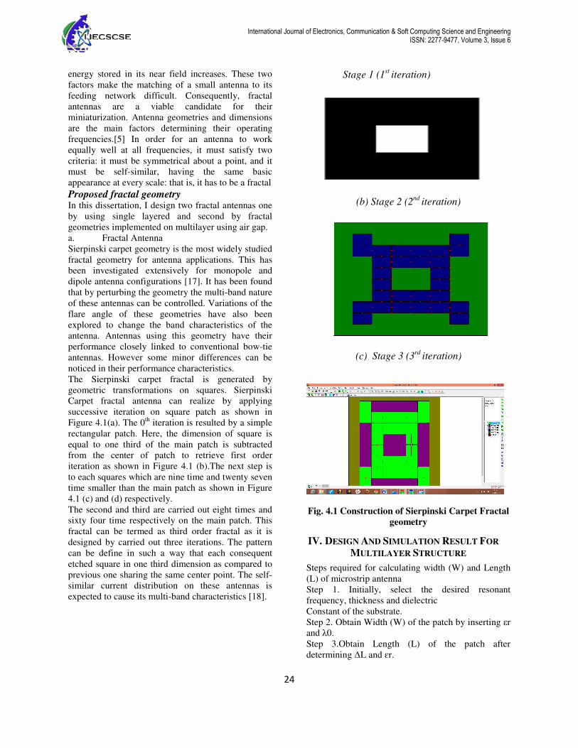
The Sierpinski carpet fractal is generated by
geometric transformations on squares. Sierpinski
Carpet fractal antenna can realize by applying
successive iteration on square patch as shown in
Figure 4.1(a). The 0th
iteration is resulted by a simple
rectangular patch. Here, the dimension of square is
equal to one third of the main patch is subtracted
from the center of patch to retrieve first order
iteration as shown in Figure 4.1 (b).The next step is
to each squares which are nine time and twenty seven
time smaller than the main patch as shown in Figure
4.1 (c) and (d) respectively.
The second and third are carried out eight times and
sixty four time respectively on the main patch. This
fractal can be termed as third order fractal as it is
designed by carried out three iterations. The pattern
can be define in such a way that each consequent
etched square in one third dimension as compared to
previous one sharing the same center point. The self-
similar current distribution on these antennas is
expected to cause its multi-band characteristics [18].
Stage 1 (1st
iteration)
(b) Stage 2 (2nd
iteration)
(c) Stage 3 (3rd
iteration)
Fig. 4.1 Construction of Sierpinski Carpet Fractal
geometry
IV. DESIGN AND SIMULATION RESULT FOR
MULTILAYER STRUCTURE
Steps required for calculating width (W) and Length
(L) of microstrip antenna
Step 1. Initially, select the desired resonant
frequency, thickness and dielectric
Constant of the substrate.
Step 2. Obtain Width (W) of the patch by inserting εr
and λ0.
Step 3.Obtain Length (L) of the patch after
determining ∆L and ɛr.
International Journal of Electronics, Communication & Soft Computing Science and Engineering ISSN: 2277-9477, Volume 3, Issue 6
25
The three essential parameters for the design of a
rectangular Microstrip Patch Antenna:
Frequency of operation (fo): The resonant frequency
of the antenna must be selected appropriately. The
Mobile Communication Systems uses the frequency
range from 2100-5600 MHz Hence the antenna
designed must be able to operate in this frequency
range. The resonant frequency selected for my design
is 2.4 GHz.
Dielectric constant of the substrate (εr): The
dielectric material selected for our design is FR4
which has a dielectric constant of 4.4. A substrate
with a high dielectric constant has been selected since
it reduces the dimensions of the antenna.
Height of dielectric substrate (h): For the Microstrip
patch antenna to be used in cellular phones, it is
essential that the antenna is not bulky. Hence, the
height of the dielectric substrate is selected as1.5
mm.
Hence, the essential parameters for the design are:
fo= 2.4 GHz εr = 4.4
h = 1.5 mm
Simulation Setup The software used to model and
simulate the Microstrip patch antenna is ZelandInc’s
IE3D. IE3D is a full-wave electromagnetic simulator
based on the method of moments. It analyzes 3D and
multilayer structures of general shapes. It has been
widely used in the design of MICs, RFICs, patch
antennas, wire antennas, and other RF/wireless
antennas. It can be used to calculate and Return loss
plot, VSWR, current distributions, radiation patterns
etc. For design simplicity of the conventional MSA,
the patch’s length and width are shows in the table
5.2. Here two different geometry fractal antenna
simulated and observe all antenna parameters like
Return loss plot, VSWR, radiation patterns,
Directivity, Gain and efficiency. Then compare both
result and investigated advantages of applying
Sierpinski carpet. The Inset feed used at point (8, 0) to design the
rectangular patch antenna. The center frequency is
selected as the one at which the return loss is
minimum. The bandwidth can be calculated from the
return loss (RL) plot. The bandwidth of the antenna is
said to be those range of frequencies over which the
return loss is below than -7.5 dB. The Implemented
Sierpinski carpet antenna simulated return loss data
and its operating frequency are as shown figure.
a. Return Loss Plot for Ist Iteration
Fig. (a) Return Loss Graph of Carpet single layer
Antenna
b. Return Loss Plot for 2nd
Iteration
Fig. (b) Return Loss Graph of 2nd
Iteration Sierpinski
Carpet Antenna
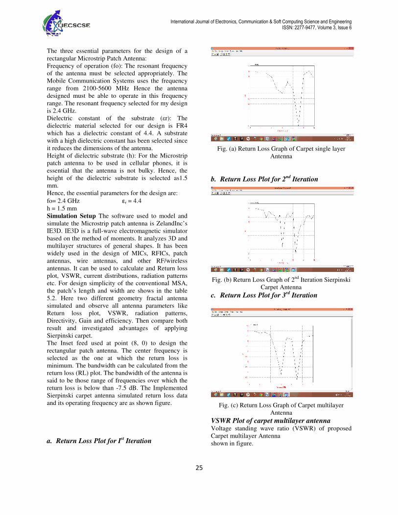
c. Return Loss Plot for 3rd
Iteration
Fig. (c) Return Loss Graph of Carpet multilayer
Antenna
VSWR Plot of carpet multilayer antenna Voltage standing wave ratio (VSWR) of proposed
Carpet multilayer Antenna
shown in figure.

International Journal of Electronics, Communication & Soft Computing Science and Engineering ISSN: 2277-9477, Volume 3, Issue 6
26
Fig (d)VSWR Plot of Carpet Antenna
Gain vs. Frequency Plot
Gain vs. Frequency Plot of carpet multilayer
Antenna
Directivity vs. Frequency Plot of carpet
multilayer antenna
The gain of an antenna is essentially a measure of the
antenna’s overall efficiency. If an antenna is 100%
efficient, it would have a gain equal to its directivity.
Shown in figure.
Radiation pattern for 6 GHz
For 5 GHz frequency.
For 9 GHz frequency
See the figure represents 2D radiation pattern and 3D
radiation pattern respectively.

International Journal of Electronics, Communication & Soft Computing Science and Engineering ISSN: 2277-9477, Volume 3, Issue 6
27
V. CONCLUSION This Paper work presents new concept of
implementation of Fractal geometry on multilayer
Sieperinski Carpet fractal geometry and designed
multiband antenna.The aim of this paper work is to
find how implementation Sieperinski Carpet fractal
geometry on multilayer gives better result in
achieving antenna parameters like return loss
(RL),VSWR, antenna efficiency ,Gain, directivity
and bandwidth. In this paper work I first design
multiband Carpet fractal microstripe patch antenna
and simulate its results with IE3D software. I find
that as iteration increases, there is increase in number
of bands. Hence fractal geometry is a used to obtain
multiband application antennas but after more than
3rd
iteration system.
REFERENCES [1] Homayoon Oraizi ,Senior Member, IEEE and Shahram
Hedayati,” Miniaturized UWB Monopole Microstrip Antenna
Design by the Combination of Giuseppe Peano and Sierpinski
Carpet Fractals” IEEE Antenna and Wireless Propagation Letter,
vol.-10,no.-,pp.67-70.2011.
[2] Homayoon Oraizi, Senior Member, IEEE and Shahram
Hedayati,” Miniaturization of Microstrip Antennas by the Novel
Application of the Giuseppe Peano Fractal Geometries” IEEE
Transaction on Antenna and Propagation, vol.- 60, NO. 8,
pp.3559-3567 August 2012.
[3] Kin-Lu Wong, Senior Member, IEEE, Gwo-Yun Lee, and
Tzung-Wern Chiou, “Low-Profile Planar Monopole Antenna for
Multiband Operation of Mobile Handsets”,IEEE Transaction on
antenna and propagation, vol.- 51. No.- 1, pp. 121-125.January
2003.
[4] Eko Tjipto Rahardjo, Fitri Yuli Zulkifli and Desi
Marlena,“Multiband Microstrip Antenna Array for WiMAX
Application”, Microwave Conference, 2008, APMC2008; Asia-
Pacific, Year: 2008, PP:1– 4. ISBN 978-1-4244-2642-3.
[5] Douglas H. Werner', Randy L. Haupt ,and Pingjuan L.
Werner “Fractal Antenna Engineering: The Theory and Design of
Fractal Antenna Arrays” IEEE Antennas and Propagation
Magazine, vol.- 41, No. 5 PP. 37-58., October I999,
[6] Abolfazl Azari, ”A New Super Wideband Fractal Microstrip
Antenna” IEEE Transaction on Antenna and propagation, vol.- 59,
no. 5, 1724-1727 MAY 2011. ISSN 0018-926X.
[7] B. R. Franciscatto ,T. P. Vuong and G. Fontgalland, ” High
gain Sierpinski Gasket fractal shape antenna designed for RFID”,
Microwave & Optoelectronics Conference (IMOC), SBMO/IEEE
MTT-S International.PP.239-243,2011. ISBN978-1-4577-1662-1.
[8] Leonardo Lizzi,Andrea Massa,” Dual-Band Printed Fractal
Monopole Antenna for LTE Applications”, IEEE Antennas and
wireless propagation letter, vol.- 10, PP. 760-763. 2011.
[9] AsitK.Panda, ManojK. Panda and SudhansuS. Patra “A
Compact Multiband Gasket Enable Rectangular Fractal Antenna”
International Conference on Computational Intelligence and
Communication Systems.PP.11-14. 2011 ISBN 978-1-4577-2033-
8.
[10] Homayoon Oraizi, Senior Member, IEEE and
ShahramHedayati, “Circularly Polarized Multiband Microstrip
Antenna Using the Square and Giuseppe Peano Fractals” IEEE
Transactions on antenna and propagation, vol. - 60, NO. 7,
PP.3466 -3470. July 2012.
[11] Ashish A. Lale, Bhagwan V. Khiste and Sanjay Khobragade,
“Study of Sierpinski triangle gasket” Microwave &
Optoelectronics Conference (IMOC),SBMO/IEEE MTT-S
International.vol.- 3,PP 386-390,2011 ISBN 978-1-4244-8679-3.
[12] L. S. Araújo, C. P. does Nascimento Silva, L. C. Barbosa, A.
J. Belfort de Oliveira, “A novel Sierpinski carpet fractal dipole,”
Microwave & Optoelectronics Conference (IMOC), SBMO/IEEE
MTT-S International.PP960—967, 2011.ISBN 978-1-4577-1662-
1.
[13] Muhammad Waqas, Zubair Ahmed, Mojeeb Bin Ihsan,
“Multiband Sierpinski Fractal Antenna” Multi topic Conference.
INMIC 2009. IEEE 13th International.PP.1-6, 2009 Print ISBN
978-1-4244-4873-9.
[14] Keng-Chih Lin, Chih-Hao Lin, and Yi-Cheng Lin “Simple
Printed Multiband Antenna with Novel Parasitic-element Design
for Multi-standard Mobile Phone Applications” IEEE Transaction
on Antenna vol.- 61,Isuee 1,2012 PP.488-491.
[15] Steven R. Best, “A Multiband Conical Monopole Antenna
Derived From a Modified Sierpinski Gasket”, IEEE Antennas and
Wireless Propagation Letters, vol.- 2,PP. 205-207.2003
[16] Duixian Liu and Brian Gaucher “A New Multiband
Antenna for WLAN/Cellular Applications”, IEEE Antennas and
Propagation Magazine, vol.-1, no.4, August2011.PP 243-246,ISSN
1090-3038
[17] David Pozar “Microstrip Antennas” Published in Antennas
and propagation IEEE Transactions on vol.45 issue 2, pp. 287-296.
1997, ISSN 0018-926X.
[18] Tian Tiehong, Zhou Zheng, “A Novel Multiband Antenna:
Fractal Antenna”, International conference , Proceedings of ICCT
vol.-2 issue 1pp. 1907-1910.2010
[19] Qi Luo, J.R.Pereira and H.M.Salgado, “Tunable Multiband
Antenna with an Active Artificial Magnetic Conductor Ground
Plane”, Microwave Conference (EuMC), 2010 European, Year:
2010, PP: 461 – 464, Print ISSN 978-1-4244-7232-1.
[20] Philip Tang and Parveen Wahid, “Hexagonal Fractal
Multiband Antenna “The IEEE Transaction on Antenna, vol.-4,
pp.554-5571997.ISBN 0-7803-7330-8.
AUTHOR’S PROFILE
ALOK DWIVEDI
M.Tech Student[EC]
JNCT, REWA
Has done B.E(ECE) in 2011 & is
currently pursuing M.Tech. in
Electronics & Communication under
the guidance of asst. professor Sumit
Dubey from JNCT, Rewa affiliated to
RGPV, Bhopal
SUMIT DUBEY
Asst. Proff., EC Department
JNCT, REWA
Has done B.E. & M.Tech. From DAV
(Indore). He is currently assistant
professor in Electronics &
Communication department of JNCT,
Rewa. He has teaching experience of
more than 4 years

International Journal of Electronics, Communication & Soft Computing Science and Engineering ISSN: 2277-9477, Volume 3, Issue 6
28
ANIL MISHRA
HOD, EC Department,
DEAN ACADEMIC
JNCT, REWA
Has done B.E., M.Tech. & is currently
pursuing P.H.D. He is currently Dean
Academic of JNCT, Rewa. He is also
the H.O.D. of Electronics &
Communication department in JNCT,
Rewa. He has teaching experience of
more than 5 years