wk 3 lec04 polygon scan conversion - the college of ...cs5600/slides/wk 3 lec04 polygon scan...
TRANSCRIPT

Utah School of Computing Spring 2013
Computer Graphics CS5600
Scan Conversion
CS5600 Computer Graphics
Spring 2013Lect
ure
Set
4
Review
• Line rasterization– Basic Incremental Algorithm – Digital Differential Analyzer
• Rather than solve line equation at each pixel, use evaluation of line from previous pixel and slope to approximate line equation
– Bresenham• Use integer arithmetic and midpoint
discriminator to test between two possible pixels (over vs. over-and-up)
Rasterizing Polygons• In interactive graphics, polygons rule the world
• Two main reasons:– Lowest common denominator for surfaces
• Can represent any surface with arbitrary accuracy
• Splines, mathematical functions, volumetric isosurfaces…
– Mathematical simplicity lends itself to simple, regular rendering algorithms
• Like those we’re about to discuss…
• Such algorithms embed well in hardware
Rasterizing Polygons• Triangle is the minimal unit of a polygon
– All polygons can be broken up into triangles• Convex, concave, complex
– Triangles are guaranteed to be:• Planar
• Convex
– What exactly does it mean to be convex?
Convex Shapes
• A two-dimensional shape is convex if and only if every line segment connecting two points on the boundary is entirely contained.
Triangularization
• Convex polygons easily triangulated
• Concave polygons present a challenge
Utah School of Computing Spring 2013
Computer Graphics CS5600
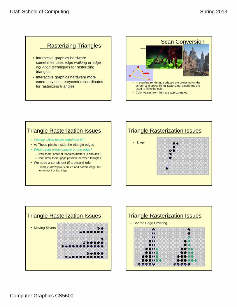
Rasterizing Triangles
• Interactive graphics hardware sometimes uses edge walking or edge equation techniques for rasterizing triangles
• Interactive graphics hardware more commonly uses barycentric coordinates for rasterizing triangles
Scan Conversion
• In scanline rendering surfaces are projected on the screen and space filling ‘rasterizing’ algorithms are used to fill in the color.
• Color values from light are approximated.
Triangle Rasterization Issues
• Exactly which pixels should be lit?
• A: Those pixels inside the triangle edges
• What about pixels exactly on the edge?– Draw them: order of triangles matters (it shouldn’t)
– Don’t draw them: gaps possible between triangles
• We need a consistent (if arbitrary) rule – Example: draw pixels on left and bottom edge, but
not on right or top edge
Triangle Rasterization Issues
• Sliver
• Moving Slivers
Triangle Rasterization Issues Triangle Rasterization Issues• Shared Edge Ordering

Utah School of Computing Spring 2013
Computer Graphics CS5600
Utah School of Computing Spring 2013
Computer Graphics CS5600
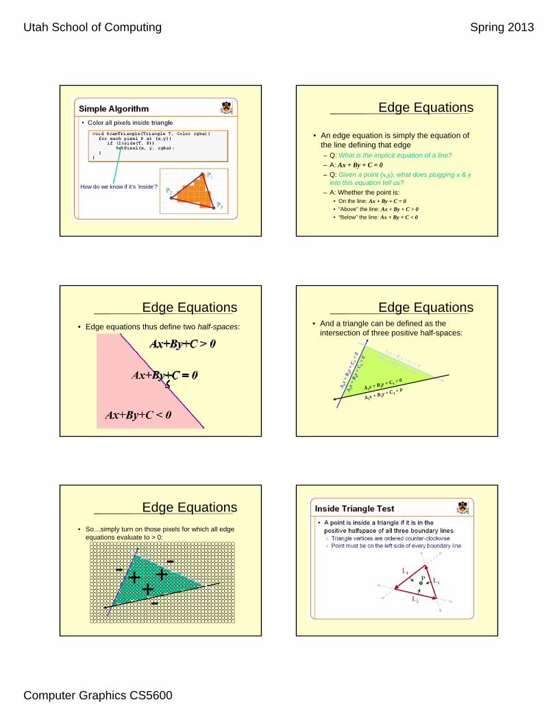
How do we know if it’s ‘inside’?
Edge Equations
• An edge equation is simply the equation of the line defining that edge– Q: What is the implicit equation of a line?
– A: Ax + By + C = 0
– Q: Given a point (x,y), what does plugging x & yinto this equation tell us?
– A: Whether the point is:• On the line: Ax + By + C = 0
• “Above” the line: Ax + By + C > 0
• “Below” the line: Ax + By + C < 0
Edge Equations• Edge equations thus define two half-spaces:
Edge Equations• And a triangle can be defined as the
intersection of three positive half-spaces:
A1x + B1y + C1< 0
A2 x + B
2 y + C2 < 0
A 3x
+ B 3
y +
C 3<
0
A1x + B1y + C1> 0
A 3x
+ B 3
y +
C 3>
0 A2 x + B
2 y + C2 > 0
Edge Equations
• So…simply turn on those pixels for which all edge equations evaluate to > 0:
+++
-
--

Utah School of Computing Spring 2013
Computer Graphics CS5600
Sweep-line
• Basic idea: – Draw edges vertically
• Interpolate colors up/down edges
– Fill in horizontal spans for each scanline• At each scanline, interpolate
edge colors across span
Sweep-line: Notes
• Order three triangle vertices in x and y– Find middle point in y dimension and compute if it is to the
left or right of polygon. Also could be flat top or flat bottomtriangle
• We know where left and right edges are.– Proceed from top scanline downwards (and other way too)
– Fill each span
– Until bottom/top vertex is reached
• Advantage: can be made very fast
• Disadvantages: – Lots of finicky special cases
Sweep line: Disadvantages
• Fractional offsets:
• Be careful when interpolating color values!
• Beware of gaps between adjacent edges
• Beware of duplicating shared edges

Utah School of Computing Spring 2013
Computer Graphics CS5600
Polygon Scan Conversion
Intersection Points
Other points in the span

Utah School of Computing Spring 2013
Computer Graphics CS5600
Determining Inside vs. Outside
• Use the odd-parity rule– Set parity even initially
– Invert parity at each intersection point
– Draw pixels when parity is odd, do not draw when it is even
• How do we count vertices, i.e., do we invert parity when a vertex falls exactly on a scan line?
Vertices and Parity
• How do we count the intersecting vertex in the parity computation?
Scan line
?????
Vertices and Parity
• We need to either count it 0 times, or 2 times to keep parity correct.
• What about:
• We need to count thisvertex once
Scan line
?????
Vertices and Parity
• If we count a vertex as one intersection, the second polygon gets drawn correctly, but the first does not.
• If we count a vertex as zero or two intersections, the first polygon gets drawn correctly, but the second does not.
• How do we handle this?– Count only vertices that are the ymin vertex for that line
Vertices and Parity
• Both cases now work correctly
Horizontal Edges• How do we deal with horizontal edges?
Don’t count their vertices in the parity calculation!
???

Utah School of Computing Spring 2013
Computer Graphics CS5600
Top Spans of Polygons
• Effect of only counting ymin :– Top spans of polygons are not drawn
– If two polygons share this edge, it is not a problem.
– What about if this is the only polygon with that edge?
Shared Polygon Edges
• What if two polygons share an edge?
• Solution:– Span is closed on left and
open on right (xmin x < xmax)
– Scan lines closed on bottom and
open on top (ymin y < ymax)
Draw Last polygon wins
Orange last Blue last
General Pixel Ownership Rule
• Half-plane rule:A boundary pixel (whose center falls exactly on an edge) is not considered part of a primitive if the half plane formed by the edge and containing the primitive lies to the left or below the edge.
• Consequences:– Spans are missing the right-most pixel
– Each polygon is missing its top-most span
Shared edge
Applies to arbitrary polygonsas well as to rectangles....
General Polygon Rasterization
• Consider the following polygon:
• How do we know whether a given pixel on the scanline is inside or outside the polygon?
A
B
C
D
E
F
Polygon Rasterization
• Inside-Outside Points
Polygon Rasterization
• Inside-Outside Points
Utah School of Computing Spring 2013
Computer Graphics CS5600
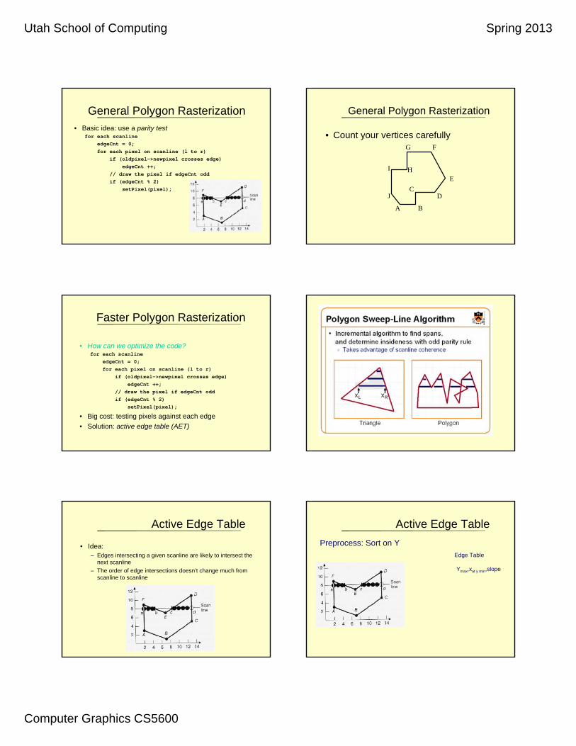
General Polygon Rasterization• Basic idea: use a parity test
for each scanline
edgeCnt = 0;
for each pixel on scanline (l to r)
if (oldpixel->newpixel crosses edge)
edgeCnt ++;
// draw the pixel if edgeCnt odd
if (edgeCnt % 2)
setPixel(pixel);
General Polygon Rasterization
• Count your vertices carefully
B
CD
E
FG
I H
J
A
Faster Polygon Rasterization
• How can we optimize the code?for each scanline
edgeCnt = 0;
for each pixel on scanline (l to r)
if (oldpixel->newpixel crosses edge)
edgeCnt ++;
// draw the pixel if edgeCnt odd
if (edgeCnt % 2)
setPixel(pixel);
• Big cost: testing pixels against each edge
• Solution: active edge table (AET)
Active Edge Table
• Idea: – Edges intersecting a given scanline are likely to intersect the
next scanline
– The order of edge intersections doesn’t change much from scanline to scanline
Active Edge Table
Preprocess: Sort on Y
Edge Table
Ymax,xat y min,slope

Utah School of Computing Spring 2013
Computer Graphics CS5600
Active Edge Table
Preprocess: Sort on Y
Edge Table
Ymax,xat y min,slope
AB:
Active Edge Table
Preprocess: Sort on Y
Edge Table
Ymax,xat y min,slope
AB: 3 7 -5/2CB:
Active Edge Table
Preprocess: Sort on Y
Edge Table
Ymax,xat y min,slope
AB: 3 7 -5/2CB: 5 7 6/4CD:
Active Edge Table
Preprocess: Sort on Y
Edge Table
Ymax,xat y min,slope
AB: 3 7 -5/2CB: 5 7 6/4CD: 11 13 0DE:
Active Edge Table
Preprocess: Sort on Y
Edge Table
Ymax,xat y min,slope
AB: 3 7 -5/2CB: 5 7 6/4CD: 11 13 0DE: 11 7 6/4EF:
Active Edge Table
Preprocess: Sort on Y
Edge Table
Ymax,xat y min,slope
AB: 3 7 -5/2CB: 5 7 6/4CD: 11 13 0DE: 11 7 6/4EF: 9 7 -5/2FA:

Utah School of Computing Spring 2013
Computer Graphics CS5600
Active Edge Table
Preprocess: Sort on Y
Edge Table
Ymax,xat y min,slope
AB: 3 7 -5/2CB: 5 7 6/4CD: 11 13 0DE: 11 7 6/4EF: 9 7 -5/2FA: 9 2 0
Active Edge Table
Preprocess: Sort on Y
Edge Table
Ymax,xat y min,slope
AB: 3 7 -5/2CB: 5 7 6/4CD: 11 13 0DE: 11 7 6/4EF: 9 7 -5/2FA: 9 2 0
What about Ymin?
Active Edge Table
Preprocess: Sort on Y
Edge Table
Ymax,xmin,slope
Active Edge Table
• Algorithm: scanline from bottom to top…– Sort all edges by their minimum y coord (last slide)
– Starting at smallest Y coord with in entry in edge table
– For each scanline:• Add edges with Ymin = Y (move edges in edge table to AET)
• Retire edges with Ymax < Y (completed edges)
• Sort edges in AET by x intersection
• Walk from left to right, setting pixels by parity rule
• Increment scanline
• Recalculate edge intersections (how?)
– Stop when Y > Ymax for edge table and AET is empty
Active Edge Table
• Algorithm: scanline from bottom to top…– Sort all edges by their minimum y coord (last slide)
– Starting at smallest Y coord with in entry in edge table
– For each scanline:1. Add edges with Ymin = Y (move edges in edge table to AET)
2. Retire edges with Ymax < Y (completed edges)
3. Sort edges in AET by x intersection
4. Walk from left to right, setting pixels by parity rule
5. Increment scanline
6. Recalculate edge intersections (how?)For every non-vertical edge in the AET update x for the new y(calculate the next intersection of the edge with the scan line).
– Stop when Y > Ymax for edge table and AET is empty
Active Edge Table Example
Example of an AET containing edges {FA, EF, DE, CD} on scan line 8:
1. : (y = 8) Get edges from ET bucket y (none in this case, y = 8 has no entry)
2. : Remove from the AET any entries where ymax = y (none here)
3. : sort by X
4. : Draw scan line. To handle multiple edges, group in pairs: {FA,EF}, {DE,CD}
5. : y = y+1 (y = 8+1 = 9)
6. : Update x for non-vertical edges, as in simple line drawing.
(FvDFH pages 92, 99)
Current X SlopeY val
Scanline 8
2 3 9 13
Utah School of Computing Spring 2013
Computer Graphics CS5600
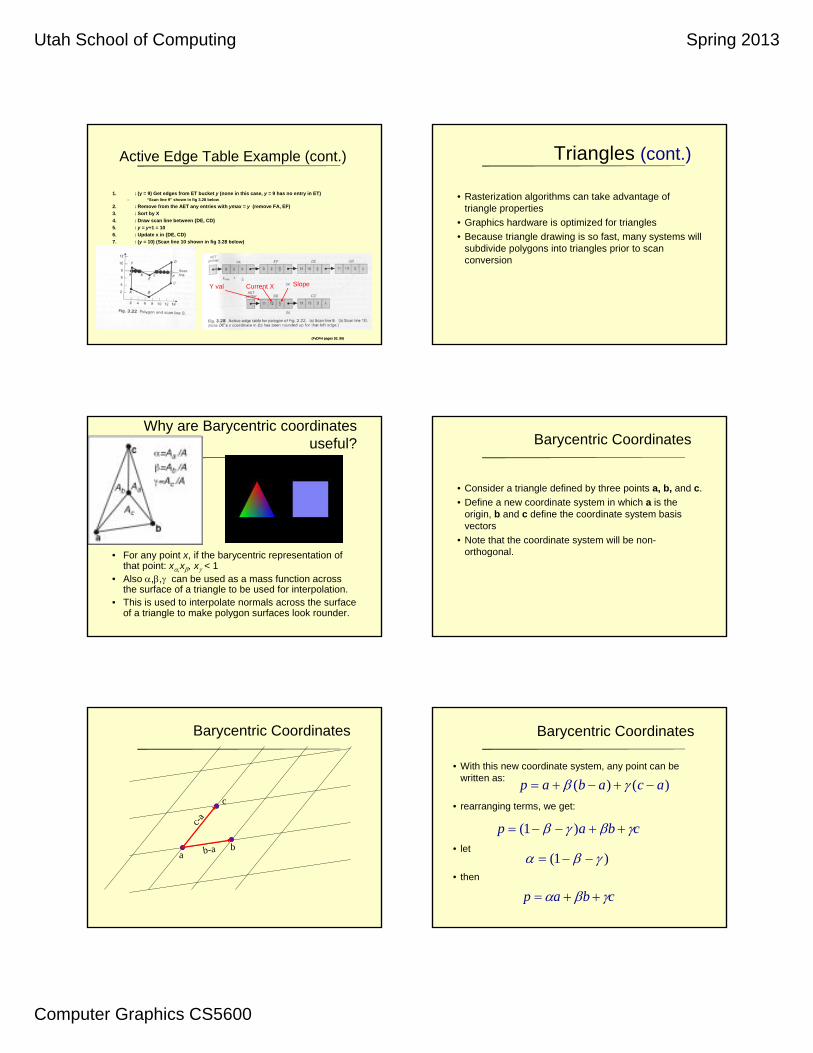
Active Edge Table Example (cont.)
1. : (y = 9) Get edges from ET bucket y (none in this case, y = 9 has no entry in ET)– “Scan line 9” shown in fig 3.28 below
2. : Remove from the AET any entries with ymax = y (remove FA, EF)
3. : Sort by X
4. : Draw scan line between {DE, CD}
5. : y = y+1 = 10
6. : Update x in {DE, CD}
7. : (y = 10) (Scan line 10 shown in fig 3.28 below)
8. And so on…
(FvDFH pages 92, 99)(FvDFH pages 92, 99)
Current X SlopeY val
Triangles (cont.)
• Rasterization algorithms can take advantage of triangle properties
• Graphics hardware is optimized for triangles
• Because triangle drawing is so fast, many systems will subdivide polygons into triangles prior to scan conversion
Why are Barycentric coordinates useful?
• For any point x, if the barycentric representation of that point: x,x, x < 1
• Also ,, can be used as a mass function across the surface of a triangle to be used for interpolation.
• This is used to interpolate normals across the surface of a triangle to make polygon surfaces look rounder.
Barycentric Coordinates
• Consider a triangle defined by three points a, b, and c.
• Define a new coordinate system in which a is the origin, b and c define the coordinate system basis vectors
• Note that the coordinate system will be non-orthogonal.
Barycentric Coordinates
a
c
bb-a
c-a
Barycentric Coordinates
• With this new coordinate system, any point can be written as:
• rearranging terms, we get:
• let
• then
)()( acabap
cbap )1(
)1(
cbap

Utah School of Computing Spring 2013
Computer Graphics CS5600
Barycentric Coordinates
a
c
bb-a
c-a
=0
=-1 =
1 =2
= -1
=0
= 1
= 2
Barycentric Coordinates
• Now any point in the plane can be represented using its barycentric coordinates
• If
• then the point lies somewhere in the triangle
cbap
10
10
10
1
Barycentric Coordinates
• If one of the coordinates is zero and the other two are between 0 and 1, the point is on an edge
• If two coordinates are zero and the other is one, the point is at a vertex.
• The barycentric coordinate is the signed scaled distance from the point to the line passing through the other two triangle points
a
c
b
c-a
=0
=-1
=1
d=1
Computing Barycentric Coordinates
• Implicit form between two points (a,b) and (a,c)
abbaabba yxyxyxxxyybaf )()(),(
accaacca yxyxyxxxyycaf )()(),(
Barycentric Coordinates
a
c
bb-a
c-a
=0
=-1 =
1 =2
= -1
=0
= 1
= 2
PDF Slides

Utah School of Computing Spring 2013
Computer Graphics CS5600
Computing Barycentric Coordinates
• To compute the barycentric coordinates of a point:
abbacabcba
abbaabba
yxyxyxxxyy
yxyxyxxxyy
)()(
)()(
accabacbca
accaacca
yxyxyxxxyy
yxyxyxxxyy
)()(
)()(
1
Barycentric Coordinate Applet
http://i33www.ira.uka.de/applets/mocca/html/noplugin/inhalt.html
Rasterize This!(Rasterization intuition)
• When we render a triangle we want to determine if a pixel is within a triangle. (barycentric coords)
• Calculate the color of the pixel (use barycentric coors).
• Draw the pixel.• Repeat until the triangle is appropriately filled.
Rasterization Pseudo Code
Rasterization Rasterization
Utah School of Computing Spring 2013
Computer Graphics CS5600
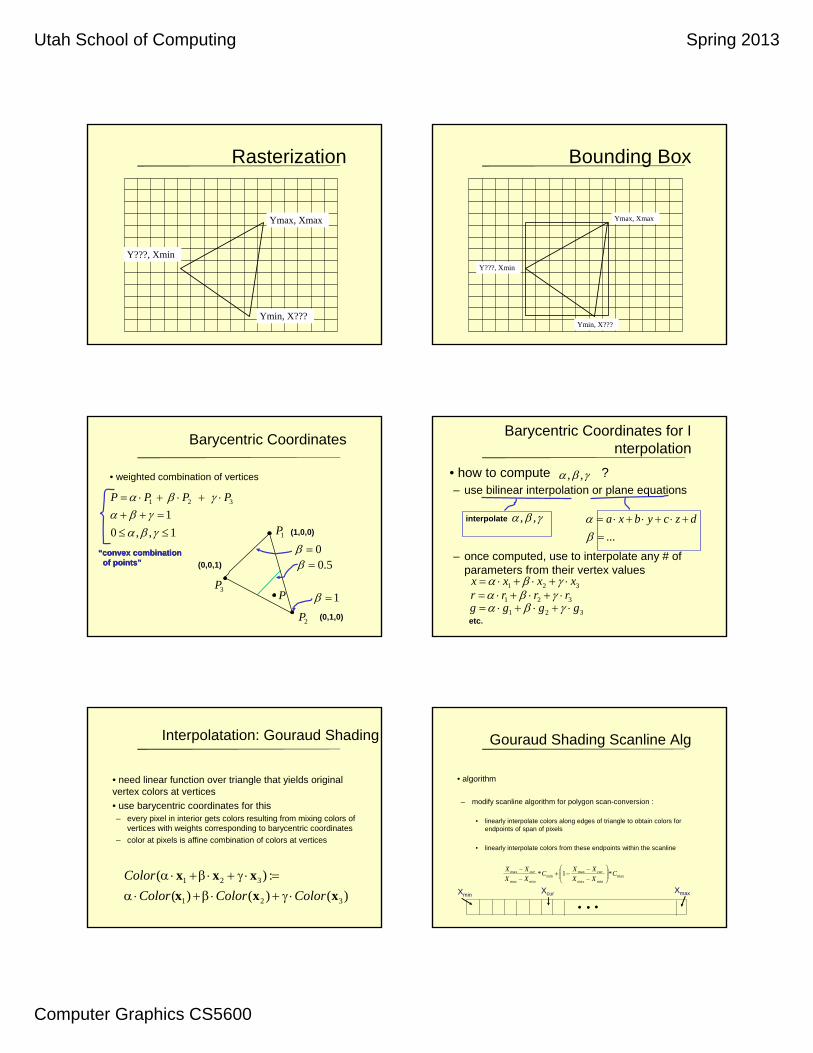
Rasterization
Ymax, Xmax
Ymin, X???
Y???, Xmin
Bounding Box
Ymax, Xmax
Ymin, X???
Y???, Xmin
Barycentric Coordinates
• weighted combination of vertices
321 PPPP
1P
3P
2P
P
(1,0,0)(1,0,0)
(0,1,0)(0,1,0)
(0,0,1)(0,0,1) 5.0
1
01,,0
1
““convex combinationconvex combinationof pointsof points””
Barycentric Coordinates for Interpolation
• how to compute ? – use bilinear interpolation or plane equations
– once computed, use to interpolate any # of parameters from their vertex values
,,
interpolate interpolate ,,
...
dzcybxa
321 xxxx 321 rrrr
321 gggg etc.etc.
Interpolatation: Gouraud Shading
• need linear function over triangle that yields original vertex colors at vertices
• use barycentric coordinates for this– every pixel in interior gets colors resulting from mixing colors of
vertices with weights corresponding to barycentric coordinates
– color at pixels is affine combination of colors at vertices
)()()(
:)(
321
321
xxx
xxx
ColorColorColor
Color
Gouraud Shading Scanline Alg
• algorithm
– modify scanline algorithm for polygon scan-conversion :
• linearly interpolate colors along edges of triangle to obtain colors for endpoints of span of pixels
• linearly interpolate colors from these endpoints within the scanline
maxminmax
maxmin
minmax
max *1* CXX
XXC
XX
XX curcur
XminXmaxXcur

Utah School of Computing Spring 2013
Computer Graphics CS5600
Filling Techniques
• Another approach to polygon fill is using a filling technique, rather than scan conversion
• Pick a point inside the polygon, then fill neighboring pixels until the polygon boundary is reached
• Boundary Fill Approach:– Draw polygon boundary in the frame buffer
– Determine an interior point
– Starting at the given point, do• If the point is not the boundary color or the fill color
Set this pixel to the fill color
Propagate to the pixel’s neighbors and continue
Filling Techniques
• Flood Fill Approach:– Set all interior pixels to a certain color
– The boundary can be any other color
– Pick an interior point and set it to the polygon color
– Propagate to neighbors, as long as the neighbor is the interior color
• This is used for regions with multi-colored boundaries
Region to be filled
Propagating to Neighbors
• Most frequently used approaches:– 4-connected area
– 8-connected area
4-connected 8-connected
Fill Problems
• Fill algorithms have potential problems
• E.g., 4-connected area fill:
Starting point Fill complete
Fill Problems• Similarly, 8-connected can “leak” over to another
polygon
• Another problem: the algorithm is highly recursive– Can use a stack of spans to reduce amount of recursion
Starting point Fill complete
Utah School of Computing Spring 2013
Computer Graphics CS5600
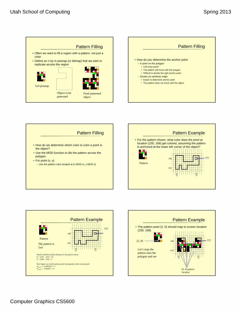
Pattern Filling• Often we want to fill a region with a pattern, not just a
color
• Define an n by m pixmap (or bitmap) that we wish to replicate across the region
5x4 pixmap
Object to be patterned
Final patterned object
Pattern Filling
• How do you determine the anchor point– A point on the polygon
• Left-most point?
• The pattern will move with the polygon
• Difficult to decide the right anchor point
– Screen (or window) origin• Easier to determine anchor point
• The pattern does not move with the object
Pattern Filling
• How do we determine which color to color a point in the object?
• Use the MOD function to tile the pattern across the polygon
• For point (x, y)– Use the pattern color located at (x MOD m, y MOD n)
Pattern Example
• For the pattern shown, what color does the pixel at location (235, 168) get colored, assuming the pattern is anchored at the lower left corner of the object?
Pattern
???
235
225
168
163
Pattern Example
Pattern
???
235
225
168
163The pattern is 5x4
Need to find the relative distance to the point to draw:X = (235 – 225) = 10Y = (168 – 163) = 5
Next figure out which pattern pixel corresponds to this screen pixel:Xpattern = 10 MOD 4 = 2Ypattern = 5 MOD 5 = 0
Pattern Example
• The pattern pixel (2, 0) should map to screen location (235, 168)
(2, 0)
Let’s map the pattern onto the polygon and see
???
235
225
168
163
(0, 0) pattern location
Utah School of Computing Spring 2013
Computer Graphics CS5600
The End
Scan Conversion
Lect
ure
Set
4
103