wiz - c rapid application development for the pic ... · wiz - c registration this demonstration...
TRANSCRIPT

WIZ - C
Rapid Application development for the PIC Microcontroller
Demonstration Manual
WIZ - C is well featured development environment for Windows ’95, ’98, 2000, XP and NT. The program, and its support files and example programs are
© Copyright Robin Abbott, 2004. <[email protected]>.
The program may be installed onto the hard disk of only one Personal Computer, and must removed by deleting the executable file, and all the support files before installing onto a different computer.
Forest Electronic Developments
orest
lectronicDevelopments
12 Buldowne Walk Sway Hampshire SO41 6DU Sales : +44 - (0)1590 - 681511
Or see the Forest Electronic Developments home page on the world wide web at the following URL:
http:\\www.fored.co.uk
1

WIZ - C Registration
This demonstration version of WIZ - C supplied for download from the web is a demonstration version which will not operate with any project other than the supplied demonstration project. However the full functionality of the application designer and simulator may be explored with the demonstration version.
Unlocking the demonstration version
To unlock the demonstration version and make available the full functionality of the program you need to send us the serial number for WIZ - C. In both programs this may be found under the Register menu option. Once we have accepted payment we will send you the registration key which will enable your program, we will also send the CD-ROM for the programs by normal post. The CD-ROM version does not require unlocking and will operate without a key. You can pay for the normal version or the professional version, we will send you the correct key to unlock normal, or professional version functionality.
You may pay by credit card (VISA or Mastercard), by email, or by fax, or send payment by post, or use bank transfer (ask us for details). The best payment method for credit card is to use our secure web site accessible through our web pages (below) - when you do this add the serial number to the comments box at the end of the checkout procedure.
The cost of enabling the program is shown on our web pages or write/email for details.
FED may be contacted at:
12 Buldowne Walk, Sway LYMINGTON Hampshire ENGLAND SO41 6DU
Phone/Fax : 01590-681511 International : +44-1590-681511
Email : [email protected]
Web Site : http://www.fored.co.uk
2

Introduction Welcome to WIZ - C, Forest Electronic Developments’ series of rapid application development environments. It allows you to select software library components (elements) from a palette, set their parameters by drop down lists, check boxes and verified text entry. It will generate the main application, initialisation code and main loop automatically and considerably speeds the front end development of PIC projects.
WIZ - C includes the full functionality of the FED PIC C Compiler, and PICDESIM - the FED development and simulation environment. WIZ - C can be configured not to use the application designer in which case it behaves exactly like the FED PIC C Compiler. WIZ - C can also load FED PIC C Compiler projects and handles them identically to the compiler.
This document is split into three, this first part includes a simple tutorial for the demonstration which shows how easy the system is to use. The second part is a full PICDESIM tutorial for the simulator, and the third part is the WIZ - C reference.
You are recommended to run through the demonstration in detail – if you wish to upgrade to the full version you are also recommended to run through the examples in the full version introductory manual as these cover new topics which are not applicable for the demonstration version.
C It is expected that users of WIZ - C will be familiar with the C programming language. The WIZ - C CD ROM is supplied with an introductory manual to C "Learn to Use C with FED", it is recommended that this is read if unfamiliar with C.
Demonstration This demonstration version is intended to show how to use WIZ - C, the simulator and the external device simulation. It is not possible to save files from the editor, open other projects, or compile any code other than the demonstration project. It is possible to experiment with the application designer, generate and compile the demonstration project and use the simulator with the project to the full including the wave window.
It is possible to upgrade the demonstration version to full functionality (either of the normal, or professional versions) by purchasing an activation key from FED. The CD-ROM will be sent by normal mail at the same time as the activation key.
Installation The program is installed from CD-ROM or from the file downloaded from our web site. For the CD-ROM insert into the CD drive and an opening menu should come up. Alternatively run the program "SETUP.EXE" from the CD. For the web version download the program to a spare directory and run Setup.EXE.
It is strongly suggested that (at least initially) the program is installed in the default directory which will allow the example projects to operate correctly.
The manual is supplied as an Adobe Acrobat (PDF) Format file, a copy of Acrobat is supplied on CD-ROM and can be installed from the opening menu. The manual is duplicated in the help files which are accessible under the Help menu.
Running the program Following installation there will be a new program group on the start menu, called WIZ - C. Double click the icon titled “WIZ - C” to start the program. The program will start and open the demonstration project. You may find that the project doesn't fit on the screen so you can use the menu option Window | Arrange Neatly to make it fit.
At this point you are recommended to run through the demonstration project in detail.
Demonstration Project – a simple LCD terminal. In the example project we will look at the development and simulation of a complete program using WIZ - C.
The program we will look at is designed for a 16F877 processor. The application will undertake the following simple functionality:
1) It will have a serial interface which may be connected to a standard PC using a 9 pin socket. 2) It will have a hex keypad 3) It will have two LED’s – red and green. 4) It will have a 2 line by 16 character LCD.
3

When a byte is received on the serial interface it will be shown on the LCD. As each byte is received it will be displayed in the next position on the display filling up each line at a time. When a key is pressed on the hex keypad the ASCII value of the key (from 0 to 9, or A to F) will be sent to the serial interface. Finally whenever a byte is received the Red LED will toggle (if it is on it will go off, if it is off it will go on), and whenever a key is pressed the green LED will toggle. The hex keypad will be debounced and keys will automatically repeat if they are held down.
By using the application designer we only need to write 10 lines of code to achieve this functionality.
We will simulate this device by using the real device simulation capability of WIZ - C.
The circuit will be based on the FED 40 pin PIC Development board. This is fully described in the manual available from our web site : http://www.fored.co.uk . The LCD and hex keypad attach to Port E and Port D. The serial interface connects to port C using the internal hardware of the PIC, the LED’s are connected to Port B bits 0 and 1.
Starting the project
For the demonstration program much of the functionality has already been included. We will add some new elements to the application designer, look at the lines of C Code which need to be written and then run and simulate the code.
We assume that you have run WIZ - C as described above and are looking at the demonstration project.
The window on top is called the application designer. The application designer holds software elements in groups at the top of the window. A software Element is a library subroutine, or software component, which may be used within an application. The application designer allows software elements to be selected for use within the current application. The software elements are grouped by type.
There are other windows – ignore these for the present.
At the bottom of the application designer there is the element store – this holds the elements used on this project. In this case we have a keypad, an LCD, and the Timer 0 element. The Timer 0 element has been included automatically by the keypad element – it is used by the keypad element to time debounce and repeat periods. If you click each element in the element store you will see the element shown on the PIC and its connections to PIC pins. Note that the keypad and LCD share some pins on the PIC. You will also see the items on the parameters tab change as you click each in turn – the use of parameters will become clear as we run through the demonstration.
Using elements within the application
The first element that we will add is the serial interface. There are 3 asynchronous serial interface elements all under the Data tab. Select the Data tab and hover over an element with the mouse - a small help box will appear with the element name. Select the element called "Interrupt driven serial interface" by clicking it. The element icon looks like this:
Now right click the element and a pop up menu will appear. Select the menu option "Help on selected element" and read through the help file entry for this element. It probably won't all make sense at the moment.
Now you can add this element to the project by double clicking it, or by dragging it on to the picture of the PIC. Do this and the element will appear in the element store at the bottom of the application designer. A picture of the element in a box will appear on the drawing of the PIC.
Note that the element will have connected its pins to the PIC Port C, bits 6 and 7 which are the PIC hardware USART interface connections. They are called Rx and Tx. This element uses the same pins of the PIC whenever it is used.
Now we must set the parameters of the serial interface. Click the parameters tab and the parameters for this element will be displayed. The "Serial Bit Rate" should be selected to 19200. The “Use XON/XOFF flow control” option should be turned off – this is only used for controlling interface to an attached PC. The Receive and Transmit buffer sizes control how much RAM is reserved in the PIC for holding bytes received and due to be transmitted. Note that owing to the operation of the serial interface on most PC’s the Receive Buffer Size should be set to 32. In our example we can leave these set to 32 and 8 bytes respectively.
Some software elements including this serial interface element allow the user to define software functions to be called automatically when events occur. An event is described in the Applications designer as an Occurrence. In this case the Occurrence is that a byte has been received on the serial interface. When a byte has been received we would like to display the received character. Click the Occurrences tab and a list of occurrences will be displayed, in this case there are two occurrences “TxFree” and “RxByte”.
4

Click on the occurrence RxByte to select it. In the "Calls for Occurrence" box type DisplayChar and then click Add. The function DisplayChar will now be shown in the list of calls for this occurrence. Further functions could be added here if wished. Now whenever a byte is received the function DisplayChar will be called automatically – we will write the function DisplayChar later.
This completes the initialisation for the interrupt driven serial element.
Now we can add both LED outputs which are on pins B0 and B1. Click the Ports Tab at the top and add the "Port Driver" element by double clicking it, or by dragging to the PIC picture. The element looks like this:
Click the tab titled "Connect Pins". The drawing of the PIC will widen and you should be able to see the names of the element connections to the outside world on the element. In our example the LED output will be on pin PORTB, bit 0. Click pin RB0 of the PIC and it will turn red, now click the element pin called "Out0" and the element serial output will be connected to pin B0. Now we would like to name this pin LEDTx. Click the pin Out0 and both ends of the link will turn red to show that it is selected. In the Pin Name box enter “LEDTx” and the pin will be renamed. Click the Parameters tab and set the initial value of the output to 0.
Now undertake the same procedure to connect another port driver to pin B1 – call this pin LEDRx.
We have now completed the work with the application designer - our application will include initialisation, code and data for all the main functions of the application. Examine the picture of the PIC - it should look like this, don't worry about the order of names on the pins of the PIC as it is dependant on the order of element selection.
MCLR/ Vpp/ THV
RA0/ AN0
RA1/ AN1
RA2/ AN2/ VRef-
RA3/ AN3/ VRef+
RA4/ T0CKI
RA5/ SS/ AN5
RE0/ RD
LCDE
RE2/ CS
Vdd
Vss
Osc1/ Clkin
Osc2/ Clkout
RC0/ T1OS0/ T1CKI
RC1/ T1OS1/ CCP2
RC2/ CCP1
RC3/ SCK/ SCL
Row1
Row2 LCDRS/ Row3
LCDRW/ Row4
RC4/ SDI/ SDA
RC5/ SDO
Tx
Rx
LCDData0/ Col1
LCDData1/ Col2
LCDData2/ Col3
LCDData3/ Col4
Vss
Vdd
LEDTx
LEDRx
RB2
RB3/ PGM
RB4
RB5
RB6/ PGC
RB7/ PGD
16F877 You can print the PIC by right clicking the PIC graphic and using the Print PIC option of the pop menu. You can copy a picture of the PIC to the clipboard and paste into other applications by using the Copy PIC option of the same menu.
The elements which have been provided for you are the keypad and display. Click on the keypad element and the Occurences tab. Note that we have defined a function called KeyPressed which will be called whenever a key is pressed.
Generating the application for the first time
We have now selected the initial set of elements for the application, and the parameters, inputs, outputs, and occurrence calls have been defined, the application may be generated. To do this right click the PIC graphic and use the menu option Generate Application or use the small blue button at the top left of the application designer. The project window on the top right will show three files and a box titled "Compiler Options" will be shown, this allows the C Compiler options to be set. Click OK and the project will compile and assemble.
5
All being well there should be no errors. If there are errors then it is almost certainly because the LED pins have been wrongly named, or because the occurrences have the wrong names – check and correct if necessary.
Now we would like to add some application specific code to the project. For the demonstration version this has already been done, however we can look at the code which has been created.
Double click the file “Demo_user.c” in the project window to open it. This file is produced automatically the first time that an application is generated (and is not generated again after that).
Examine the file.
There are three functions at the top of the file – UserInterrupt, UserInitialise and UserLoop. The blank template for these functions is automatically created when the program is first generated.
UserInterrupt is called as part of the interrupt routine, it is not used here. UserInitialise holds one line of C Code: LCDClear();
This clears the display when the program starts.
UserLoop is called as part of the main application loop. It is empty in this example.
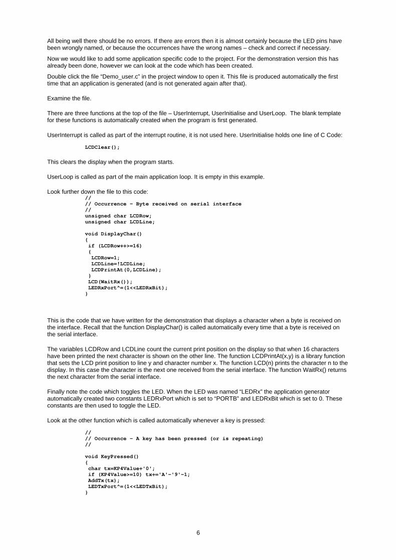
Look further down the file to this code: // // Occurrence - Byte received on serial interface // unsigned char LCDRow; unsigned char LCDLine; void DisplayChar() { if (LCDRow++>=16) { LCDRow=1; LCDLine=!LCDLine; LCDPrintAt(0,LCDLine); } LCD(WaitRx()); LEDRxPort^=(1<<LEDRxBit); }
This is the code that we have written for the demonstration that displays a character when a byte is received on the interface. Recall that the function DisplayChar() is called automatically every time that a byte is received on the serial interface.
The variables LCDRow and LCDLine count the current print position on the display so that when 16 characters have been printed the next character is shown on the other line. The function LCDPrintAt(x,y) is a library function that sets the LCD print position to line y and character number x. The function LCD(n) prints the character n to the display. In this case the character is the next one received from the serial interface. The function WaitRx() returns the next character from the serial interface.
Finally note the code which toggles the LED. When the LED was named “LEDRx” the application generator automatically created two constants LEDRxPort which is set to “PORTB” and LEDRxBit which is set to 0. These constants are then used to toggle the LED.
Look at the other function which is called automatically whenever a key is pressed: // // Occurrence - A key has been pressed (or is repeating) // void KeyPressed() { char tx=KP4Value+'0'; if (KP4Value>=10) tx+='A'-'9'-1; AddTx(tx); LEDTxPort^=(1<<LEDTxBit); }
6

The variable KP4Value is defined within the library and is set to the number of the key pressed on the hex keypad. It will range from 0 to 15. This code converts the number from 0 to 15 to an ascii code from ‘0’ to ‘9’ or from ‘A’ to ‘F’ and transmits the byte on the serial port. It also toggles the Tx LED.
To look at the help file entry for any of these functions click on the function name (e.g. AddTx) and press Ctrl and F1.
We can also look at the autocode functions which help to write the code. (Bear in mind for the demonstration version that any changes to the code will be lost). Press Ctrl + End to go to the bottom of the file. Right click the edit window to bring up the menu and use the Autocode option (you could also press ALT and Enter). Use the Element Calls/Vars menu option to bring up a list of library functions for the elements that we are using. Select one with the mouse (e.g. LCDOnOff) to insert the function call and help information for that function. You can also use autocode to insert comment blocks, blank functions and loops.
Press Ctrl+F9 to create the application again.
This is now the completed application which can be programmed into a PIC16F877 and run directly. However we can also simulate it and look at the results on the waveform analyser.
Simulation It is not the intention of the demonstration manual for WIZ - C to cover all the simulation capabilities of PICDESIM which is covered in the later section. However we can check the operation of the program. It is possible to simulate with a stimulus file or with direct simulation of the external devices. Here we'll use simulation of the external devices.
Switching screen layouts
There is a large amount of information provided on the screen and to aid users there are 3 main views :
Compact Press ALT+C keys Debugging Press ALT+D keys Editting Press ALT+C keys
In compact mode all windows (Debug, Project, Editting and Information) are shown on screen. In Editting mode the debug window is hidden and most screen space is given to the edit window. In Debugging mode most space is given to the debug window.
FED recommend that users get used to using the ALT and C, D or E keys to rapidly switch views. Normally only the ALT+D and ALT+E modes will be use, the compact mode is provided for existing users and is similar to previous versions of our environments.
Simulating with external devices
Press Alt and D to bring up the debugging view.
WIZ - C has the capability to simulate LED's, switches, LCD displays and a number of other devices which might be connected to the PIC.
Look at the debugging window. We have already added an LCD, both LED’s and the hex keypad to the example. We’ll look here at adding the terminal and then we can run the program for real.
Use the Simulate | Add External Device menu option. A dialog box will come up. In the External Device type box select Terminal. There are a number of parameters and values which may be selected for each device. For the terminal we need to run at 19200bps. Look in the parameters box, select the Bit Rate option, and from the drop down box select 19200. Ignore the other two parameters.
Under the Connections box there is a list box called Pins with two entries "Terminal Rx" and "Terminal Tx". Select Terminal Rx and then use the Port box to select Port C, use the Bit box to select bit 6. Do the same for Terminal Tx, but connect to Port C bit 7. Note that the terminal Rx (receive pin) connects to the PIC Tx (transmit pin) and vice versa.
Click OK and note how the Terminal now appears on the debugging window. Click and drag the window bar to move the terminal somewhere convenient.
Note – we could have done this using the application designer by selecting the USART element and then clicking the small light bulb button to automatically generate the terminal and its connections, this is faster, but we wanted to demonstrate the range and use of external devices here.
We now have all 5 devices connected to the PIC. If you want to see how the other devices are connected then right click the description above the device and select the Edit option.
The top of the debugging window should look like this:
7

Note that the LED’s are illuminated. This is because the simulator assumes all unconnected inputs to be logic 1. Look at the top of the screen, find the slider labelled “Update Rate”. This should be one notch from the extreme right, (this is the fastest rate which the simulator will run at whilst displaying variables as they update).
Now run the simulation by using the Simulate | Run menu option (you could also press F9, or use the button of the running man on the toolbar).
The LED’s will go out. Click the terminal box (the cursor will appear) and type the letter A. Watch the LED go on, and the letter ‘A’ is shown on the LCD. Press ‘B’, the LED will go out. Press the keypad buttons with the mouse – watch the LED toggling and the values shown on the terminal. Hold a keypad button down and watch as the key auto-repeats.
If it doesn’t appear to work. Have you moved the Update Rate slider ? Have you correctly assigned the RxByte occurrence of the terminal window to the DisplayChar routine ? Have you correctly assigned the Tx and Rx pins of the terminal (right click the title “Terminal” and use the edit menu option to change it).
You may also like to look at the LCDRow and LCDLine variables shown in the Watch tab of the debugging window. As you enter characters into the terminal window note how they are updated with the print position on the LCD.
Stop the program.
Now look at the information bar – the yellow bar to the left of the edit window. If the bar is not showing click the button to the top left of the edit window to turn it on (similarly click again to turn it off). Now the information bar can be set to show the address of each program line in the source, the time at which the line was last executed, or the number of times that it has been executed – click the buttons along the top of the edit window to select each option.
You can also determine how long a function or block of code takes to execute. Select a block of code – say the following block :
if (LCDRow++>=16) { LCDRow=1; LCDLine=!LCDLine; LCDPrintAt(0,LCDLine); } LCD(WaitRx()); LEDRxPort^=(1<<LEDRxBit); }
Now select the block of code with the mouse by clicking down before the void and dragging to the end of the function – you will see a box at the bottom of the edit window which will show the total time between the selected lines – in this case 4uS - the picture below shows the relevant part of the window:
8

You can drag over any area of code and the edit window will show the total time taken to execute that code provided that it has been simulated.
Using the waveform analyser
Now we want to run the program until time 500mS (half a second) and then stop to check the inputs and outputs. Select the debugging window and select the Break tab. Right click the window and select the Add Breakpoint option. (You could also use the Simulate | Add Breakpoint menu option.)
The Breakpoint Definition dialog box will be shown. Select "Break at Time", and then in the At Time box enter 500m, click the OK button to define the breakpoint. Reset the simulation using “Simulate | Reset Processor” or the blue button with a 0 on the tool bar.
Now run the program by using the Simulate | Run menu option (you could also press F9, or use the button of the running man on the toolbar). Wait until the breakpoint is hit at 500mS. The code will stop in the middle of an assembler statement – the cursor will stop on the line where the breakpoint was hit.
Use the Tools | Examine Wave Window menu option. The Wave Window "Define Trace Format" dialog box will be shown. In the Trace Name box select "Port D Pins", and then click the "Add as 8 line traces button". Resize the window to a comfortable size.
Press the F8 key repeatedly button to zoom out until the waveform occupies about 500mS (F7 zooms in if you’ve gone too far). The window can be copied to the clipboard or printed by using the options in the File menu for the Wave Window.
Look at the traces – at about 30mS you can see the LCD being initialised and then a repeating pattern on bits 0 to 3 as the rows of the keypad are strobed.
Return to the WIZ - C application. In the toolbar at the top of the main window slow the simulation down by by dragging the slider to the left a few notches. Reset the simulation and run it again. This time press a few keys in the terminal window. Wait until 500mS passes and examine the wave window again. You should be able to see a dramatic difference as characters are written to the LCD – note how the keypresses represented by long low periods on D0 to D3 result in data being written to the LCD.
You can experiment with the keypad. In the wave window use the Trace | Add Trace menu option to add PORT C bits 6 and 7 and PORT B bits 0 and 1 to the waveform window to see how these operate. You can move the vertical cursors around points of interest and press F6 to zoom up the wave between the cursors. Do this with PORT C bits 6 and 7 to watch serial information in detail.
Finally you can profile the performance of the program. Reset the program and run it until 500mS and use the Simulate | View Profile menu option. Many of the calls shown are internal to the compiler however you can see the KeyPressed and DisplayChar functions in the list (if you have pressed a key or sent a byte). Most of the time spent in these functions is within the library routines.
You are recommended to read through the simulator tutorial which is next within this manual to see some of the other simulation capabilities. However in the demonstration version, when it is not registered, you will not be able to add stimulus or injection files.
9

WIZ - C Registration
This version of WIZ - C supplied for download from the web is a demonstration version which will not operate with any project other than the supplied demonstration project. However the full functionality of the application designer and simulator may be explored with the demonstration version.
Unlocking the demonstration version
To unlock the demonstration version and make available the full functionality of the program you need to send us the serial number for WIZ - C. In both programs this may be found under the Register menu option. Once we have accepted payment we will send you the registration key which will enable your program, we will also send the CD-ROM for the programs by normal post. The CD-ROM version does not require unlocking and will operate without a key.
You may pay by credit card (VISA or Mastercard), by email, or by fax, or send payment by post, or use bank transfer (ask us for details). The best payment method for credit card is to use our secure web site accessible through our web pages (below).
The cost of enabling the program is shown on our web pages or write/email for details.
FED may be contacted at:
12 Buldowne Walk, Sway
LYMINGTON Hampshire ENGLAND SO41 6DU
Phone/Fax : 01590-681511 International : +44-1425-681511
Email : [email protected]
Web Site : http://www.fored.co.uk
10

FED PIC & AVR Integrated Development Environments
(WIZ-C, AVIDICY, AVRDE, PICDE & C Compilers)
Simulation System
Introductory Manual
The simulation system provided with FED’s development environment is flexible and comprehensive. The program, and its support files and example programs are
© Copyright Robin Abbott, 1996-2004. <[email protected]>.
The program may be installed onto the hard disk of only one Personal Computer, and must removed by deleting the executable file, and all the support files before installing onto a different computer.
Forest Electronic Developments
orest
lectronicDevelopments
12 Buldowne Walk Sway HAMPSHIRE SO41 6DU Sales : +44 - (0)1590 - 681511
Or see the Forest Electronic Developments home page on the world wide web at the following URL:
http:\\www.fored.co.uk
11

Simulator
Contents Simulation System
Introduction
Debugging and editing views
The Debugging Window
Debugging Windows
Working with layouts
Working with external devices
Working with Variables
How to change the program counter
Breakpoints
Running the waveform analyser
Waveform Generator
Working with Stimulus and Injection Files
Simulation Accuracy Introduction The simulation system for PIC and AVR devices is very powerful, and yet is intended for use by beginners.
Debugging and editing views There is a large amount of information provided on the screen and to aid users there are 3 main views :
Compact Press ALT+C keys
Debugging Press ALT+D keys
Editting Press ALT+C keys
In compact mode all windows (Debug, Project, Editting and Information) are shown on screen. In Editting mode the debug window is hidden and most screen space is given to the edit window. In Debugging mode most space is given to the debug window.
FED recommend that users get used to using the ALT and C, D or E keys to rapidly switch views. Normally only the ALT+D and ALT+E modes will be use, the compact mode is provided for existing users and is similar to previous versions of our environments.
The debugging window The debugging window is very flexible and allows external devices and windows which show the state of the PIC during simulation to moved and resized freely and to appear on one or more of the tabs shown at the top of the window.
Throughout this manual we’ll assume the system is set up as the default for new projects. If you wish to switch to the default the press ALT+D and then click the button shown below at the top of the debugging window which will load the default layout for the debugging window:
Tabs
The debugging window has a number of tabs at the top :
All of the sub-windows on the debugging window may be assigned to one or more of the tabs on the debugging window. By default new external devices will appear on every tab, whilst the information sub-windows (such as breakpoints) will appear only on one or two tabs.
To add or delete a tab then right click one of the tabs, the tabs menu will appear :
12
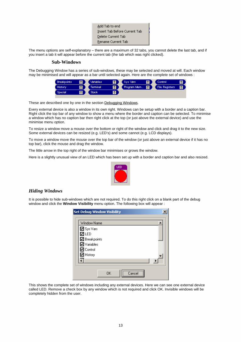
The menu options are self-explanatory – there are a maximum of 32 tabs, you cannot delete the last tab, and if you insert a tab it will appear before the current tab (the tab which was right clicked).
Sub-Windows
The Debugging Window has a series of sub-windows, these may be selected and moved at will. Each window may be minimised and will appear as a bar until selected again. Here are the complete set of windows :
These are described one by one in the section Debugging Windows.
Every external device is also a window in its own right. Windows can be setup with a border and a caption bar. Right click the top bar of any window to show a menu where the border and caption can be selected. To minimise a window which has no caption bar then right click at the top (or just above the external device) and use the minimise menu option.
To resize a window move a mouse over the bottom or right of the window and click and drag it to the new size. Some external devices can be resized (e.g. LED’s) and some cannot (e.g. LCD displays).
To move a window move the mouse over the top bar of the window (or just above an external device if it has no top bar), click the mouse and drag the window.
The little arrow in the top right of the window bar minimises or grows the window.
Here is a slightly unusual view of an LED which has been set up with a border and caption bar and also resized.
Hiding Windows
It is possible to hide sub-windows which are not required. To do this right click on a blank part of the debug window and click the Window Visibility menu option. The following box will appear :
This shows the complete set of windows including any external devices. Here we can see one external device called LED. Remove a check box by any window which is not required and click OK. Invisible windows will be completely hidden from the user.
13

Moving Windows from tab to tab
It is possible to move windows from tab to tab, or to show windows on more than one tab. By default all external devices appear on all tabs. Right click just above an external device, or right click the caption bar of a window to bring up the options available.
The Change Page menu option brings up the following box :
A list of tabs will appear – the tabs on which the window will appear may be selected and cleared. It is not possible to remove a window from every tab (in this case it will stay on the first page). If you wish to make a window invisible use the Window Visibility menu option (right click a blank part of the debugging window).
Debugging Windows
The Variables window [Default – Main Tab]
The Variables window shows a list of variables which may be added by the user. Right click the window and use Insert to include a new variable or value or to change the way a variable is examined.
Double click a variable to bring up the Modify Memory Dialog Box which allows the value to be changed, similarly double click any item in the watch window to bring up the dialog box and change its value.
The Sys Vars window [Default – Main Tab]
The Sys Vars window shows the registers, the ports, and a list of memory locations which are essential to the operation of the C Compiler. These items are automatically included after a compilation and are updated whenever they change. Double click a register to bring up the Modify Memory Dialog Box which allows the value to be changed.
The Stack Window [Default – Main Tab]
The stack window shows a listing of the stack. Double clicking a stack value will show the line in the main edit window to which the program will jump back when a return is executed at that location.
The Control Window [Default – On all Tabs]
The control window has various controls on it which affect the simulation. For WIZ and AVIDICY users the processor clock frequency is set in the Application Designer. The Change PC button allows the value of the PC to be set.
The Breakpoint Window [Default – Main, Memory and Special Tabs]
The breakpoint window shows the breakpoint list. Double click a breakpoint to edit it, press insert to create a new breakpoint, press delete to remove the selected breakpoint. Note that all breakpoints included by setting breakpoints on boxes are shown here as well. See also Breakpoints.
The Terminal window [Default – Main and Memory Tabs]
The terminal is a standard RS232 terminal which allows bytes to be sent to and received from application programs connected to the serial port. Right click the terminal window to bring up the options for it, or use the Module menu. The terminal window is selected by clicking the Terminal tab in the debugging window.
The options under the Module menu which refer to the terminal window are :
Communications. This option brings up the Set Serial Port Parameters
14

Send File. This allows a file to be transmitted over the serial port.
The Special window [Default – Special Tab]
The Special window examines a number of special internal device registers – these should be self explanatory.
Controlling the Simulation
The update rate is a slider which is shown at the top of the IDE :
At the left the value is 1. Almost at the right the value is 64000. This represents the number of cycles that the processor should execute before updating the watch variables. The higher the number then the faster the simulation. If the slider is set to the extreme right then the variables are not updated whilst running unless the “Update Now” button is pressed, or a simulation breakpoint is hit.
Also at the top of the IDE is the Stop on Errors Check Box. If enabled this will stop the simulation should an error occur during the simulation Run. If this Check Box is not selected, and if an error occurs, then errors will be printed in the Information Window, but the simulation will continue.
Working with layouts Clearly it is possible to configure the debugging window in a number of different ways, and it may be desirable to have different layouts for different projects. For example a general purpose development board may have a standard layout with a picture of the board and external devices for LED’s and LCD’s and push buttons which may be used for a number of different projects.
To this end it is possible to save the layout of the window including all the external devices. To do this right click on a blank part of the debugging window to bring up the layout menu :
Use the Save as Layout File option to save the current layout, the layout will be saved with the current tabs, external devices, window positions and visibility.
Use the Load Layout File option to delete all current devices and load up the devices and window layout in the external file. Note that it is possible to load a layout from any project file, not just those saved as layout files.
Use the Set out Windows as in Layout File option to rearrange the windows but ignores any external devices.
Use the Merge devices from Layout file option to bring in any external devices in the layout file whilst leaving all current devices and window layout intact. This is a very useful option. For example use this menu option and load the file LEDBarPortB. This is a group of 8 LED’s attached to port B bits 0 to 7 and gives a quick visual indication of the state of the pins. There are a number of predefined layouts in the Layouts sub-directory of the IDE.
Note that it is possible to merge devices from any project file, not just those saved as layout files.
There are two pre-defined layouts – Classic and Default. The classic layout is loaded automatically for projects created before version 11. The default layout is loaded for all new projects. You can quickly switch the window layout to either of these versions using the two buttons at the top left of the debugging window:
The left button switches to default view, the right button (the ‘C’ button) switches to classic view which has most of the debugging windows on their own tab.
Working with external devices This section describes the external devices which may be simulated. External devices are simulated on the debugging window immediately above the debugging control tabs. Each device has a number of inputs and outputs which may be connected to PIC pins. It is also possible to write models for new types of device.
See:
Introduction to External Devices
15

Generating devices automatically from the application designer
External Debugging Device Dialog Box
Handling External Devices
The list of external devices is as follows:
7 Segment Displays
Bitmap
Device Picture
Hex Keypad
I2C Devices
LCD Module
LED
Logic Analyser
Push Button
Potentiometer
PWM Voltmeter
Shape
Serial Terminal
Writing external device models
Introduction to External Devices
Any number of external devices may be simulated, and each type may be simulated any number of times - it is quite permissible to simulate 3 potentiometers and two LCD display modules for example.
To add an external device then use the Simulate | Add External Device menu option. This will bring up the External Debugging Device Dialog Box.
To delete the device then click on the device name above it (the name will then be underlined), use the right mouse button to bring up the menu and use the delete option.
To edit the device (to change parameters or pin connections) then click on the device name above it (the name will then be underlined), use the right mouse button to bring up the menu and use the edit option.
Generating devices automatically from the application designer
The easiest method to generate a device is to use the application designer. Click the element you wish to use as a template and press the create device button :
A device will be created with the same pin connections and parameters as the application designer. Note that not all application designer elements have associated devices and the button will only be enabled if there is an associated device.
External Debugging Device Dialog Box
This box looks like this :
16

This dialog box allows external devices to be added or edited.
The list of devices is shown in the "External Device Type" box. A device being edited cannot be changed. Select the device type in this box.
The parameters box shows a list of parameters for the device. For example "Colour" or "Bit Rate". Click on a parameter to select it and the Value box will show a list of available options. Click on the option to be used for the device.
The connections box shows a list of pins for the device. Each pin may be left unconnected, connected low (to 0V), high (to +5V), or connected to any of the pins of the PIC. In the connection list choose Low or High for the relevant logic level, use the Port options to connect to a pin on that port..
Some devices allow each pin to have their own parameter. In this case the Parameter and Value boxes may be selected for each pin.
Please note that the external devices have no concept of drive impedance. The PIC pins when set to inputs default in the simulator to a high state. Thus if an LED anode is connected to a PIC pin defined as an input it will see a high state and will illuminate if the cathode is low, in a real device this would not happen. This is unlikely to be a problem for the great majority of applications which will set outputs to drive during initialisation.
The layer shows how the device will be drawn. Devices on layer 0 will always appear over devices on layer 1 and so on. Some devices such as bitmaps and shapes appear on lower levels by default.
Finally the name of the device (shown on the debugging window above the device) may be typed into the "Name" box. Clear this box if the device does not need a name.
Handling external devices
It is possible to undertake a number of actions with external devices. It is important to understand that the menu for a device will only appear if the caption is clicked. The caption is the name which appears just above the device. If there is no caption because the name is blank then simply right click just above the device.
To select one or more devices. Click the device in the caption area, to select more devices use the shift key to select others, to select all devices in an area then click and hold the mouse outside the area and drag a rectangle round all devices to be selected :
17

To group devices so that moving or copying one device will move or copy all of the group together. Then select all the devices to be grouped, right click just above one of them (in the caption of the device) and use the group option.
To ungroup devices. Then select one of the devices in the group, right click on the caption area and use the ungroup menu option.
To delete a device. Then select a device, right click the caption area and use the Delete menu option, alternatively select it and use the delete key..
To duplicate a device. Then select a device, right click the caption area and use the Duplicate menu option, this will create an exact copy including all the pin connections.
To align devices so that they are all lined up on screen then select the devices, right click them and use the Align menu option, it is possible to line them up horizontally, vertically or space them on screen equally.
7 Segment Displays
The 7 segment display device emulates a 7 segment display. The display is shown at full brightness when the common pin is enabled. However when the common pin is disabled the display shows the last pattern at half brightness. This enables multiplexed displays to be simulated.
Parameters Options Notes
Colour Red, Green The colour of the display
Segment Drive Low, High Selects whether the PIC pin needs to be low to turn on the segment or high.
Common Drive Low, High Selects whether the Common pin needs to be low to turn on the display or high. Note that the PIXIE and WIZPIC 7 segment elements assume that a drive transistor will be used to turn on a display. So these elements drive the Segment and Common pins in the same sense.
Show Unlit Bars No, Yes Unlit bars may be displayed (as dark gray bars) if desired.
Connections Parameters Notes
SegA to SegG None The 7 segments of the display.
DP None Decimal point, leave unconnected if not required.
Common None The common pin for the display.
18

Bitmap
The Bitmap device allows a bitmap to be loaded and shown on the debugging window as a background. For example a picture of a development board can be loaded and devices placed on top of the board such as LED’s or LCD’s
There are no parameters or pins for this device – just click the FileName button and load the correct file which may be in bmp or jpg format.
Clock Generator
The clock generator will send a series of pulses into the device on the connected pin. It is possible to set the minimum and maximum frequency of the generator and then adjust the frequency using the slider.
Parameters Options Notes
Minimum Frequency Entered value The frequency of the clock when the slider is at the extreme left.
Maximum Frequency Entered value The frequency of the clock when the slider is at the extreme right.
Connections Parameters Notes
Clock None The clock output of the generator.
Device Picture
The Device pictrure shows an outline view of the device together with the state of all of the pins. The colour coding of the pins is as follows :
Red Device Output driving high
19

Pink Device Input being driven high
Dark Green Device Output driving low
Bright Green Device Input being driven low
White Not a device I/O pin
Blue Analog input
Parameters Options Notes
Show Pin Text Port, All, None Determines whether the text written by the pin should show the Port and pin (e.g. RA2), the full name (RA2/AN2/VRef-), or no text at all (the last being useful if the device is sized to a small scale).
Hex Keypad
The hex keypad simulates a 4x4 hex keypad with 4 rows and 4 columns. Key 0 is row 0, column 0, Key 1 is row 0, column 1 and so on up to Key F which is row 3, column 3. When a key is pressed with a mouse the device connects the input to the output. If the key is held down with the mouse then it will remain pressed.
Parameters Options Notes
PIC Drives Rows, Columns Selects whether the PIC is driving rows or columns. For the FED PIXIE elements the PIC drives the keypad rows.
Pull Ups On PIC Inputs Pull Up, Pull Down Selects whether the PIC inputs connected to the keypad are pulled up to +5V with resistors or down to ground with resistors. For the PIXIE and WIZPIC elements the PIC is connected to +5V with pull ups.
Connections Parameters Notes
Row 1 to Row 4 None The 4 rows of the display.
Col 1 to Col 4 None The 4 columns of the keypad.
I2C Devices
The I2C device provides a simulation of a I2C device on a bus through a terminal window which shows the state and values presented on the bus together with the capability to specify values to be transmitted to the PIC when the bus is read.
The terminal will display the following to show the state of the bus :
Character Meaning
s Start state p Stop state r Read bit detected at end of address w Write bit detected at end of address a Acknowledge by addressed device x No acknowledgement received XX Hex value transmitted or received on bus
Timing Violations
20

The device model measures clock width for timing violations. This follows the I2C specification, in practice many devices better this specification so if timing violations are reported then it is worth checking that clock width is within spec, and then switching the device to a higher rate to prevent these warnings.
Parameters Options Notes
Device Rate High Speed (3.4MHz) Selects the device rate for timing Standard (400KHz) checks. Switch to a higher rate if Low Speed (100KHz) timing violations are received, but the
Device itself is within specification.
Address Length 7 Bits, 10 Bits Selects whether the device accepts 7 or 10 bit addressing.
Address Range Low Entered Value Lower value of the range of addresses which will be accepted by the device. The range of addresses acknowledged by the device will run from this address to the Address Range High value.
Address Range Upper Entered Value Upper value of the range of addresses which will be accepted by the device.
Byte To Read Entered Value Byte value which will be read from the device on the bus should the address be within range.
Connections Parameters Notes
SDA None The IIC SDA connection.
SCL None The IIC SCL connection.
LCD Module
The LCD module simulates LCD modules of up to 80 characters based on the Hitachi chipset. The module simulation includes reading of busy flag (and the timing delays in the real module are simulated accurately). Full initialisation and 4 bit and 8 bit transfer mode are supported. CG RAM is simulated for read and write, but the user defined characters are not simulated, similarly the character set shown is ASCII rather than an accurate representation of the ROM based character set. The cursor is not simulated, however shift and display commands are all accurately simulated.
Parameters Options Notes
Rows 1, 2 or 4 The number of rows on the display. Note that 4x20 row displays behave like 2 rows of 40 characters with a line break.
Chars Per Row 8, 16, 20, 32, 40 The number of characters per row on the display.
Connections Parameters Notes
E None The E pin of the display
RS None The RS pin of the display
R/W None The Read/Write pin for the display. Note that some display drivers only write to the display - for this type of drive the R/W pin can be connected low.
DB0-DB7 None The data pins of the display. For a 4 bit interface only DB4-DB7 are used, the other pins can be left unconnected.
LED
21

The LED device simulates a simple LED which may be resized. The LED will light when the Anode is positive and the Cathode is negative. To Simulate drive through a transistor each pin may be specified as connected through a drive transistor in which case the sense of the pin drive will be inverted.
Parameters Options Notes
Colour Red, Green, Yellow, White or Blue The colour of the LED..
Shape Round, Rectangle, Arrow right, Arrow left, Triangle The shape of the LED..
Connections Parameters Notes
Anode Transistor Drive The Anode of the LED - must be high to illuminate the LED. If transistor drive is set to yes then the LED will illuminate when the PIC Anode pin is low.
Cathode Transistor Drive The Cathode of the LED - must be low to illuminate the LED. If transistor drive is set to yes then the LED will illuminate when the PIC Cathode pin is high.
Logic Analyser
The Logic analyser shows the past history of a pin in digital format as a line trace.
Parameters Options Notes
Time Per Pixel 100nS to 10S The sampling rate of the analyser, every sample is displayed as one pixel.
Display times on window Yes/No Selects the option to display the time on the logic analyser window showing the range of the displayed trace.
Connections Parameters Notes
Sample None The sample pin of the logic analyser which should be connected to an output pin of the device.
Push Button
The push button models a simple push to make switch. The switch has an input (the common pin) and an output (the contact pin). The switch may be configured to operate as a push button (the button only stays down whilst the mouse is held down over the switch). It may also be set to operate as a push-push switch (the mouse is clicked to push the switch, and clicked again to release it).
Parameters Options Notes
Caption None, A to Z The letter which appears on the push button (or a blank may be selected).
Sticky No, Yes Set to no for a push button switch, and set to Yes for a push-push switch.
Connections Parameters Notes
Contact Resistor On Pin The switch output - this should be connected to a PIC input. The resistor on pin parameter selects whether the switch output is pulled up or pulled down with a resistor. The switch will default to the pull up or pull down value when released.
Common None The input to the switch. It should be connected to a PIC output, or to high or to low.
22

Potentiometer
The potentiometer models a potentiometer connected between 0 and +5V. The output is a number from to the maximum value. The maximum value may be set as between 7 bits (127) and 16 bits (16383). The output of the potentiometer should be connected to a PIC analogue input and will then be read by the simulator when examining an A/D converter input. The slider value may be changed by dragging it with a mouse, or by using the arrow buttons to set the value accurately.
Parameters Options Notes
Maximum Value From 31 to 16383 The maximum value of the potentiometer which will drive the PIC input. For an 8 bit A/D the maximum value should be 255, for 10 bit it should be 1023 etc..
Connections Parameters Notes
Slider None The potentiometer output which should be connected to a PIC analogue input.
PWM Voltmeter
The PWM voltmeter measures the voltage produced by a PWM output by dividing the high time by the low time over a period of several PWM cycles. The result is displayed on a digital display with a resolution of 1mV.
Parameters Options Notes
High Voltage From 0.5V to 5.0V The voltage represented by high. For a standard logic output on a standard power supply this would be 5.0V.
Integration Time From 10us to 1S The time over which the voltage is measured and therefore the frequency with which the display is updated.
Connections Parameters Notes
PWM Input None The PIC output pin which should be connected to the voltmeter.
Shape
The Shape device has no connections, it allows a shape to be drawn on screen, and also allows text comments to be written..
Parameters Options Notes
Shape 5 shapes Select the shape type here. The last shape which is Text Only allows text comments to be written on screen.
Colour 11 colours Select the shape colour here.
Fill Yes/No Should the shape be filled ?
Angle Rotation Amount by which to rotate the shape, not all shapes can be rotated.
23

Serial Terminal
The serial terminal simulates a 3 wire asynchronous serial terminal using RS232 style 8 bit signalling with one start bit and one stop bit. The idle state is high. No flow control is simulated.
The terminal has 24 lines - although only 2 lines are shown - to scroll up and down click on the terminal window and use the up and down arrow keys. To send a character the terminal is clicked with the mouse and any key presses will be transmitted from the terminal. Similarly any keypresses received by the terminal are shown on the display.
Characters out of normal printing range are shown as a '\' character followed by the decimal value of the character. However Carriage Return (value 13) is shown as '\r' and line feed (value 10) is shown as '\n'. The terminal requires a line feed (Decimal 10) to select the next display line.
Parameters Options Notes
Bit Rate From 75 to 115000 The serial bit rate of the terminal from 75 bps up to 11500bps. Only standard rates may be selected.
Send CR as CR-LF Yes, No If Yes is selected then when the Enter key is pressed a character 13 followed by a character 10 will be sent. Otherwise just a 13 is sent.
2 char delay between No, Yes When selected the terminal will send characters separated by a delay equivalent to two characters. This allows time for processing in those programs which do not expect consecutive serial characters to be received..
Connections Parameters Notes
Terminal Rx None The input to the terminal. Note that this should be driven by a PIC output. (PIC Tx)
Terminal Tx None The output from the terminal, note that this should be connected to a PIC input (PIC Rx).
Writing external device models
It is possible to create new external devices in DLL files. This requires a C or C++ Compiler, but new devices may be added simply by adding the new libraries to the directory structure. The logic and clock generator devices are supplied in DLL files.
This is an advanced topic which is covered in detail in the DLL authoring manual which is supplied with source files in the Device DLLs sub-directory of the distribution CD.
Working with Variables The variables window shows the variables which can be examined whilst the program is running. Most actions concerned with watch variables are on the pop up menu of the watch list. Right click on the list to view the menu options.
To add a Watch Variable, then either use the Add Watch menu option under the Simulate Menu, or press the Insert key whilst the window is highlighted. This will bring up the Insert/Add Memory Watch Dialog Box (see below). One or more Watch Variables may be added in the Dialog Box by typing their addresses in label or numeric form separated by commas. The Browse button will display a list from which known variables may be selected. Alternatively right click on a variable name in the edit window and use the menu option to add a watch variable (or press F2).
To trace the watch variable (which allows it to be examined by the waveform analyser), then click the Trace button in the dialog box. The variable will be displayed with a * or a # to show that it is being traced.
To modify a variable in the Variable Window then select it and press enter.
24

To change the value of a variable in the Variable Window then double click it to bring up the Modify Memory Dialog Box.
To remove a Watch Variable, select it in the Variable Window and press the Delete key.
Insert/Add Memory Watch Dialog Box
The Insert/Add Memory Watch Dialog Box allows the user to enter one or more variables (memory locations) to the Variable Window. If an item is selected in the Variable Window, then the variables will be inserted before the selected item. The Dialog Box contains the following items:
Use C Definition. Professional version only. This check box should be clicked with the C Compiler (or WIZ or AVIDICY programs) if the variable is to examined using the C source as a guide to its content. The scope is also significant so within a block local variables will be shown ahead of global variables with the same name.
Trace. This check box should be clicked if the File Registers which are entered are to be traced during the run for examination in the waveform window (See Running the waveform analyser).
Names or addresses. This edit box should contain one or more expressions for File Registers. If more than one expression is to be entered, then separate items with commas e.g. SPL,SPH,temp,temp+1 will insert four variables into the Variable Window.
Display As. This allows the display shown on the Variable Window to be configured. The display may be set to Bit, Byte, Word, or Long to display the value as a bit, as 1 byte, as 2 byte, or as a 4 byte value stored in memory. The Hex Dump options shows 16 bytes starting at the defined address. The bit option simply shows the value of a single bit of the address, the bit number to be examined should be entered in the edit box.
Display Format. This controls the format of the displayed value. Values may be displayed in binary, decimal or hex. Float and Zero terminated String format may also be used The signed button may be used to display decimal values in signed notation.
Pointer. If this box is clicked then the variable is taken to be a 2 byte pointer to an item defined by the other boxes. The value of the pointer, and the contents of RAM at that location are shown. If the pointer has its top bit set (bit 15) then the pointer is assumed to point to ROM, the top bit is reset to get the ROM address.
Browse. The Browse Button brings up a list of all File Register labels defined for this Program. One or more labels may be selected which will be added to the list of addresses in the Insert File Watch Dialog Box separated by commas when the >> Button is pressed.
How to change the program counter To change the value of the PC click the PC box shown at the top of the Debug Window.
Alternatively use the Simulate | Set PC to current line menu option. This will find the address of the line that the cursor is on within the edit window and set the PC to that line.
When one of the step or run instructions is used the program will now run from the new value of the PC.
Breakpoints
Working with Breakpoints
The Simulate | Add Breakpoints menu option brings up the Breakpoints Dialog Box which allows the user to configure Program Breakpoints, or click the breakpoint window and press insert, or right click the breakpoint window and use the Add Breakpoint menu option:
Breakpoints Dialog Box
The Breakpoints Dialog Box allows the user to add or change breakpoints in the program. The Dialog Box contains the following items:
Type. There are four types of breakpoint which may be selected Unconditional Addressed : Enter an address and this breakpoint stops whenever the Program Counter reaches that address. Conditional Addressed : Enter an address and a condition and this breakpoint stops whenever the Program Counter reaches that address, and the condition is non-zero. Global Conditional : Enter an address and this breakpoint stops whenever the condition is true, regardless of the value of the Program Counter. This may be used to look for specific faults or conditions. For example enter PIR1&0x40 to stop when bit 6 of the PIR1 register is set to 1. On Time : Enter a time (e.g. 1.0mS, 250uS, or 2.5S), and the program will stop when the simulation time equals the breakpoint time.
Address. This edit box allows the user to define the address for an unconditional breakpoint or an addressed conditional breakpoint. The address can be any valid PICDE expression, which must be in the range of the processor’s program memory space. When the Break on Time button is clicked this box will be re-titled “Time”
25

Conditional Expression.. This edit box allows the user to define the Conditional Expression for a global conditional breakpoint or an addressed conditional breakpoint. The expression can be any valid PICDE expression which will stop the Program when it evaluates to a Non-Zero result, eg. test ==9. This conditional expression will stop the Program when the value of the File Register test is 9.
Browse. The Browse button brings up a list of program labels. To add a label to the address edit box then select the label and double-click it, or select a label and press the >> button.
Animate. If this checkbox is clicked then the breakpoint is an animation breakpoint. An animation breakpoint does not stop the program, it simply causes the program to update all the watch variables when it is hit. This is most useful if the update slider is at the extreme right, in this event variables are only updated when an animation breakpoint is hit (or when the Update Now button is pressed). This allows the user to follow the value of watch variables when the program passes specific points.
OK. When the OK button is pressed, then all the breakpoints in the breakpoints list, and any breakpoint which is currently being edited, are set on the current Program.
Running the waveform analyser The waveform analyser operates as a separate program, and allows the user to examine file registers which have been specially marked as for debugging. All of the ports are traced automatically. To set a watch variable as a traced variable then right click it and and use the Modify Watch menu option. Click the trace box, reset the simulation and run it - it will then be available in the waveform analyser.
Once the variables have been added to the Debug Window with the trace option set, and the simulation has been reset and then run, then the waveform analyser window may be used to examine them. Use the Tools | Waveform Trace menu option to bring up the analyser, which has its own help file and manual.
Waveform Generator The Waveform Generator is intended to allow users to design complex data and analogue patterns for injection to the pins of the device under simulation. It is a front end for the FED PIC and AVR development tools.
The wizard allows complex data patterns to be input to the PIC, clocks to be generated, or analogue waveforms to be generated for injection into the A/D converter inputs of the PIC. The waveform wizard allows a number of stimulus’ to be stored together in one file. One of more of these files may be added to the list of project files and will then be included as simulation input when the program is simulated.
Within any of the FED development environments use the Tools | Run Wave Generator menu option to start the program. A new wave generator project will be created with the same name as the current project. The wave generator file will be added to the project window which will automatically include the stimulus when the program is simulated.
The Waveform Generator is described in more detail in the introduction to the professional version supplied with the software.
Working with Stimulus and Injection Files To add or remove a Stimulus File (which contains Commands to set Port Inputs or File Variables to specific values) or Injection Files (which insert Hex Values in the Program), then use the project window.
To define a stimulus file for use in a program then add it to the project. Click the project window and press insert (or right click the window for a menu). Select one or more files in the file open dialog window (they normally have an extension of .STI). Now when the project type dialog box appears select Stimulus as the type of file.
See :
Stimulus Files
Injection Files
Stimulus Files
Stimulus files allow the user to define data which appears as if it is present on the external pins of the Processor, or to change File Registers at specific times in the Program. Up to 16 Stimulus files may be included for any one simulation.
Stimulus files have the format described below:
A time should be given, which may be in the form of a number followed by an optional letter. If only a number is given, then the time is taken to be in nanoseconds. Alternatively, the letters U, M, or S may be placed directly after the number, in which case the time will be taken in microseconds, milliseconds or seconds, respectively. The time may be given at the start of a line with a command, or on a line on its own. Times do not have to be sequential and one file may define time and stimulus information which ends after another file. The time may be given in decimal format.
26

The following lines all specify the same time - 1mS:
0.001S 1m 1000u 1000000n 1000000
To trigger an event on a key press the command onkey is given with a letter or digit :
onkey 0 onkey A
Use onkey instead of a time, now when that key is pressed the following event will be triggered.
The commands available in a Stimulus file are described individually below, they allow a value to be applied to a Register, to a bit of a Register, or clocks or asynchronous data to be injected to a bit of a Register. Each line contains a command as follows:
time Set the time for an event, follow with n,u,m or S for units all following events will occur at that time. If no units are provided then time is assumed in nS
e.g. 1000m 200n 1S 35u 1.050m
Note that times do not have to be in order - see the example at the end.
onkey Set the keyboard key to trigger a following event, note this must be on a line of its own
e.g. onkey 0 onkey 1
name=value Set specified file register defined by name to value. Note if = is given on its own then the last file register is assumed.
e.g. 1000m PORTA=76h ; At 1000mS set file PORTA ; to value 76Hex
1500m =0 ; At 1500mS set file PORTA ; to 0 onkey a PORTA:0=1 ; Set PORT A bit 0 to 1 when key 'a' is pressed
name:bit=value Set specified bit of file register defined by name to value. Note if = is given on its own then the last file register and bit set is assumed. (Note if the last assignment was to a file register then the complete file register is assumed). e.g.
1000m PORTA:0=1 ; At 1000mS set file PORTA, bit 0 ; to 1
1.5mS =0 ; At 1500mS set file PORTA, bit 0 ; to 0
STATUS:3=0 ; At 1500mS set file status, bit 3 ; to 0
serialrate-name:bit=value Inject value as an 8 bit asynchronous serial stream to the specified file (name), and bit. Note, if a name and bit value are not given then the last port and bit value are assumed. The rate is given in decimal immediately after the word serial. e.g.
10m serial9600-PORTC:0=65 ; At 10mS start the ; injection in ; serial format of the ; letter A ; to Port C, bit 0 at ; 9600bps 200m serial2400-=66 ; At time 200mS start the ; injection of letter B to ; Port C bit 0, note the ; same port as ; that used last time is ; used. ; bit rate is 2400
27
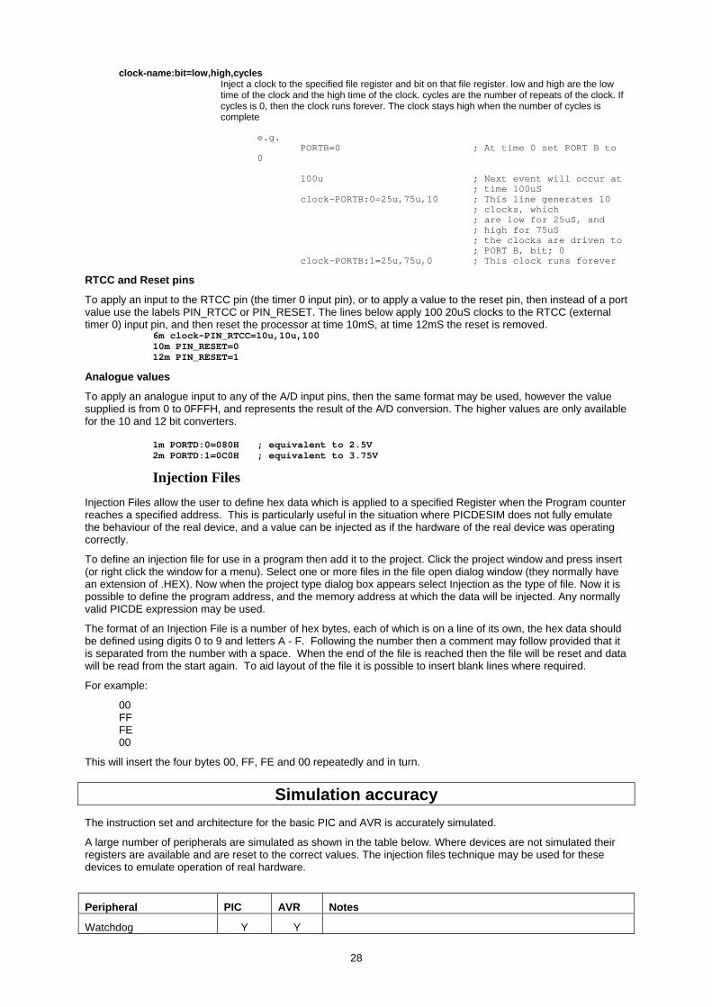
clock-name:bit=low,high,cycles Inject a clock to the specified file register and bit on that file register. low and high are the low time of the clock and the high time of the clock. cycles are the number of repeats of the clock. If cycles is 0, then the clock runs forever. The clock stays high when the number of cycles is complete
e.g.
PORTB=0 ; At time 0 set PORT B to 0
100u ; Next event will occur at ; time 100uS clock-PORTB:0=25u,75u,10 ; This line generates 10 ; clocks, which ; are low for 25uS, and ; high for 75uS ; the clocks are driven to ; PORT B, bit; 0 clock-PORTB:1=25u,75u,0 ; This clock runs forever
RTCC and Reset pins
To apply an input to the RTCC pin (the timer 0 input pin), or to apply a value to the reset pin, then instead of a port value use the labels PIN_RTCC or PIN_RESET. The lines below apply 100 20uS clocks to the RTCC (external timer 0) input pin, and then reset the processor at time 10mS, at time 12mS the reset is removed.
6m clock-PIN_RTCC=10u,10u,100 10m PIN_RESET=0 12m PIN_RESET=1
Analogue values
To apply an analogue input to any of the A/D input pins, then the same format may be used, however the value supplied is from 0 to 0FFFH, and represents the result of the A/D conversion. The higher values are only available for the 10 and 12 bit converters.
1m PORTD:0=080H ; equivalent to 2.5V 2m PORTD:1=0C0H ; equivalent to 3.75V
Injection Files
Injection Files allow the user to define hex data which is applied to a specified Register when the Program counter reaches a specified address. This is particularly useful in the situation where PICDESIM does not fully emulate the behaviour of the real device, and a value can be injected as if the hardware of the real device was operating correctly.
To define an injection file for use in a program then add it to the project. Click the project window and press insert (or right click the window for a menu). Select one or more files in the file open dialog window (they normally have an extension of .HEX). Now when the project type dialog box appears select Injection as the type of file. Now it is possible to define the program address, and the memory address at which the data will be injected. Any normally valid PICDE expression may be used.
The format of an Injection File is a number of hex bytes, each of which is on a line of its own, the hex data should be defined using digits 0 to 9 and letters A - F. Following the number then a comment may follow provided that it is separated from the number with a space. When the end of the file is reached then the file will be reset and data will be read from the start again. To aid layout of the file it is possible to insert blank lines where required.
For example:
00 FF FE 00
This will insert the four bytes 00, FF, FE and 00 repeatedly and in turn.
Simulation accuracy The instruction set and architecture for the basic PIC and AVR is accurately simulated.
A large number of peripherals are simulated as shown in the table below. Where devices are not simulated their registers are available and are reset to the correct values. The injection files technique may be used for these devices to emulate operation of real hardware.
Peripheral PIC AVR Notes
Watchdog Y Y
28

Timer 0 Y Y
Timer 1 Y Y
Timer 2 Y Y
Timer 3 Y Y
Timer 4 Y Y
CCP Y Y
PWM Y Y
Enhanced PWM N N/A Normal PWM modes for the Enhanced PWM hardware are supported
External Interrupts Y Y
Internal Interrupts Y Y
USART Y Y
EUSART N N/A
Analogue Comparators N Y
A/D Converters Y Y
Data EEPROM Y Y
Program Memory EEPROM (read and write)
Y Y
Peripheral Service Port Y N/A
Sleep Y Y
I2C N N This is known as TWI on the AVR
SPI N N
CAN N N/A All CAN registers are correctly reset and may be written or read.
USB N N/A All USB registers are correctly reset and may be written or read
29

WIZ-C
PIC Microcontroller
C based visual development for Windows Reference
WIZ-C is a well featured visual development environment for Windows ’95, ’98 and NT4.0. The program, and its support files and example programs are © Copyright Robin Abbott, 2000. <[email protected]>.
The program may be installed onto the hard disk of only one Personal Computer, and must removed by deleting the executable file, and all the support files before installing onto a different computer.
Forest Electronic Developments
orest
lectronicDevelopments
12 Buldowne Walk Sway HAMPSHIRE SO41 6DU Sales : +44 - (0)1590 - 681511
Or see the Forest Electronic Developments home page on the world wide web at the following URL:
http://www.fored.co.uk
30

Contents
Introduction The Application Designer within WIZ-C The Application Designer - concepts Using the Application Designer with existing FED PIC C projects Starting an application Selecting PIC and oscillator frequency Selecting and deleting elements Setting Element parameters Defining Occurrences Connecting pins to the PIC Listing public calls and variables Generating the application for the first time User code and the main loop - in brief Structure of generated application User defined code Processors with multiple ROM and/or RAM pages Macro Reference
31

Introduction Welcome to WIZ-C, FED's unique drag & drop, point and click development of our popular PIC C development program. Please run through our tutorial first to see some of the capabilities of the program, this manual describes the operation of WIZ-C, and explains some of the procedures that you will need to follow to make best use of the program.
The Application Designer within WIZ-C The Application Designer is the centre for selecting software library functions, connecting them to the PIC, and defining user defined functions which are called when events occur within the library function. The Application Designer has its own window within WIZ-C. To bring this window to the front use the Window | Application Designer menu option, or use the button which is at the extreme right hand side of the tool bar.
The application designer may be enabled or disabled by using the Project | Use Application Designer menu option. By default it will be enabled with a new project.
The Application Designer - concepts The application designer holds software elements in groups at the top of the window. A software Element is a library subroutine, or software component, which may be used within an application. The application designer allows software elements to be selected for use within the current application.
Elements are extremely easy to generate using the Element Editor. Existing software components or libraries may be converted into software elements using the Editor which is described in its own manual.
When an element is selected for use in the application, the application designer will automatically hook it into the application, and set up the element according to the parameters selected within the designer. The application designer allows an element to be connected to any of the inputs or outputs of the PIC. Some elements have no connections to the pins of the PIC, others have a number of connections.
Some software elements also allow the user to define software functions to be called automatically when events occur. An event is described in the Applications designer as an Occurrence.
Examples of occurrences are the internal timers overflowing, a byte being received on a serial interface, for a seven segment multiplexed display changing digit.
Some elements include other elements automatically, and hook their functions automatically into occurrences of the element which they include. An example of this is the HMS element, which generates an occurrence every second, minutes, and hour that passes. This element automatically includes the Timer 0 element which drives the hardware for timer 0. The HMS element automatically hooks its functions into the overflow occurrence of Timer 0.
Using the Application Designer with existing FED PIC C projects It is not recommended to use the application designer with existing projects until the user is very familiar with the operation of the designer.
By default the application designer will be enabled when an existing project is opened. It is recommended that it is disabled by using the Project | Use Application designer menu option when an existing project is opened.
Starting an application A new project is started in WIZ-C by using the Project | Open/New Project menu option. A file open dialog box will shown, it is recommended that a new project is started in its own directory. As soon as the file name is selected and the OK button is pressed, the blank project will be created and the application designer is presented as the top window.
It is recommended that before any user specific code is written, that the application designer is used to create the minimum application. Then user code files can be inserted into the project window.
Selecting PIC and oscillator frequency The first actions with a new project are to set up the PIC type and the oscillator frequency. The PIC type is selected with the "Change PIC" button under the element groups, the oscillator frequency may be selected from a list, or the exact value may be typed into the box. The oscillator frequency is entered in Hertz. Thus a 4MHz crystal should be entered as 4000000, however as this is a standard value it may be selected from the drop down box.
32

Selecting and deleting elements To select an element then select the tab which holds the group from which you wish to make a selection. When the mouse is held over an element a help box will appear showing the name of the element and some information about it. The elements may be double clicked, dragged on to the PIC or the right button may be used to bring up a pop up menu which will allow the selected elements to be inserted.
Some elements are the unique, in that only one copy of the element may be used at any time. Other elements, such as the level detection elements which operate on a single pin of the PIC, may be selected as many times as necessary for the application. If an element is selected which may only be used once, then attempts to select additional copies of the element will fail. Elements which may only connect themselves to a certain pins of the PIC, such as the PWM element will automatically connect themselves to the PIC when they are selected.
The elements are all shown in the element store at the bottom of the Application Designer window. Elements may be selected from the element store by clicking it with the mouse, a small red box will be shown around the selected element. The selected element has its parameters, Occurrences, its list of public calls and variables, and the connections to the PIC shown in the main application designer window. The element may be defined within the application as described below.
Setting Element parameters The parameters tab will display a list of parameters which may be changed for the selected element. Parameters may be selected as a number, or as an item from a list, or as a simple on or off selection by a check box. The full meaning of the parameters are described in the help file which may be shown for an element by right clicking it with a mouse, and using the help menu option.
Defining Occurrences An Occurrence is an event which happens, which is detected by an element. It is possible to define user functions which will be called automatically when an occurrence happens.
To do this select the occurrence tab on the application designer for the selected element. The main list box will show a list of occurrences for the current element, click one of these occurrences to select it. Type the name for the assembler label at the start of the function into the box, and click the add button to include that function in the list of functions which will be called automatically when the occurrence happens.
To delete a call from the list of occurrences select the Occurrence in the main list box, then select the call to be deleted from the drop down box at the top of the window, and click the Remove button.
When an element, such as the HMS element, automatically loads another element, it may include its own functions within the list of calls which are to be executed when the occurrence. It is important that the user should not delete any of these calls, as they will prevent the element which hooks in the selected element from operating correctly.
Connecting pins to the PIC Many elements may be connected to pins of the PIC. When an element is selected from the element store, it will be shown on the PIC outline, together with its inputs and outputs shown as pins alongside the elements within the main outline. To connect a pin from an element to a pin of the PIC, then click the pin of the PIC, and then the click the pin of the element to which it is to be connected. If the pin can be connected to that pin of the PIC then the outline will be re-drawn and the connection shown on the main PIC outline.
It is possible to connect more than one element to the same pin of the PIC, for example the LCD display driver allows the data lines to be shared with others inputs. If it is not possible to connect the element pin it to the PIC them an error box will be displayed explaining the reasons why the connection is not possible. For example the seven segment display driver element requires all segment drivers of the display to be connected to the same port, although any port may be selected for this functions.
To break a link then the connected pin of the PIC, or the element should be clicked to select the connection. The right mouse button may be used to bring up the menu, the break link option selected, or the break the link button on the Connect Pins tab used.
The PIC is shown in diagrammatic form within the application designer window. If the Connect Pins tab of the Application Designer is selected, then the outline of the PIC will be drawn in a wide form, allowing the pin names of the element, and the PIC to be read. If any of the other tabs is selected, then the outline will only show pin names on the PIC itself. The pin names shown on the PIC are those defined by Microchip, or when connected to an element, show the names of the element inputs/outputs.
The pins of the PIC will take on the name of the element pin to which they are connected. It is possible to use a customised name - for example the PortOut element sets a PIC pin to be an output and names it Out0, the second PortOut element output will be called Out1 etc.
33

It may be better and easier to understand to give them customised names - "StatusLED" and "MotorDrive" for example. The application designer will now create defines for these pins called StatusLEDPort and StatusLEDBit which can be used within the program.
To name the pins use the "Connect Pins" tab on the Application Designer. Select a pin on the current element, (or any pin of the PIC which is connected to an element) by clicking it. Then enter the name in Pin Name box on the Application Designer window - it will be shown on the PIC graphic as it is typed.
When an application is generated, the application designer will check that all element pins which must be connected are correctly connected to the PIC, if this is not the case then it will not be possible to go ahead and assemble the application.
Listing public calls and variables The interface tab of the application designer shows all the public calls and variables which may be used for the selected element. This information is of use to the programmer of the main code.
To automatically insert a blank call template for a C function for an element then press Alt and Enter whilst the cursor is in the Edit window, use the element Calls/Var option to bring up a list. Double click the required call.
Generating the application for the first time Once the initial set of elements for the application have been selected, and the parameters, inputs, outputs, and occurrence calls have been defined, the application may be generated. To do this use the pop-up menu option, Generate Application within the application designer window, or use the main menu option Assemble | Generate application, or press Ctrl+F9, or use the tool bar button.
The application designer will automatically generate three or four files and then go on to compile the application (this is described in the Compiler reference manual).
The first of these is the application designer header file. It has the name ProjectName_Auto.h where ProjectName is the name selected for the project when it was first opened. the second is the main application file named ProjectName_Main.c, which includes the initialisation code, and the main interrupt routines. It should be included in all files added to the project.
The next file is the user file. It has the name ProjectName_User.Inc. Initially this simply contains blank functions for initialisation, interrupts and main loop. Blank functions are created for occurrence calls. This is the only automatically generated file which may be modified as it will only be generated once. The functions are described in detail below.
The final file is the library file which includes all the library routines from the various library files, they are all gathered together here. It has the name ProjectName_Lib.Inc. It will not be generated if the elements use no code for library files.
The include, main and library files should not be altered at all, as they will be completely rewritten every time that the Generate Application option is used.
These files are automatically included within the project window so they will be assembled in order. Additional C files may be added or inserted freely.
After the application designer has generated the main files, and included them within the project window, the Compiler Options dialog box will be bought up allowing the project to be compiled. All of the C options may be set with this box as described in the main C reference, or simply click the Help button.
User code and the main loop - in brief All user code should be written in the ProjectName_User file, or additional files. Additional code may be added into the project in c files. To add additional files to the project window then click on a file and press insert, select a file and it will then be included before the file which was selected. Alternatively de-select all files and press insert to add a new file at the end. It is recommended that files be inserted between the _User and _Lib files. If the file is not found then it will be created. Further details are in the PICDESIM example and on-line reference.
The user file contains user generated code for initialisation, interrupts, and the main loop. The main loop is code which the PIC executes in turn - testing for occurrences, calling any attached sub-routines, and calling any library routines which need to be called regularly. User defined code may be attached to the main loop, but should return to the main loop to continue the main functions of the program.
Attaching user defined code to the ProjectName_User file is straightforward. Double click the file in the Project Window and it will open in the Edit window. The various are described in comments in the file - and in detail below.
Structure of generated application The Application Designer generated program follows the flow shown below:
34
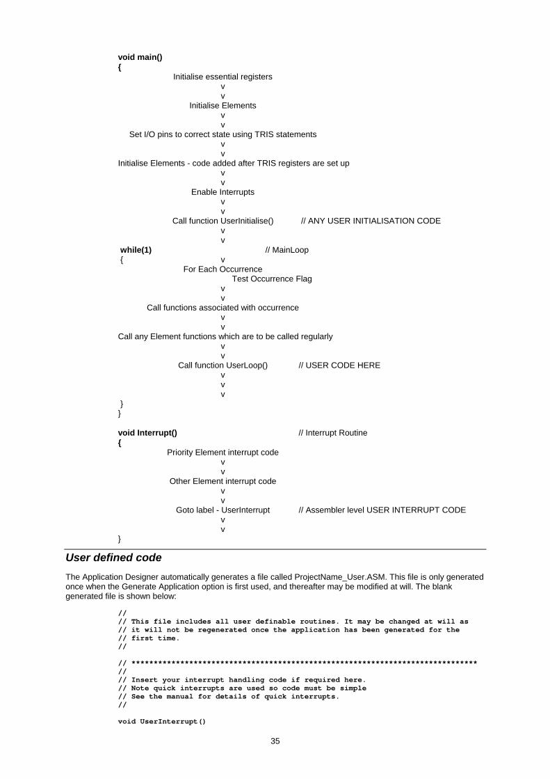
void main() {
Initialise essential registers v v Initialise Elements
v v Set I/O pins to correct state using TRIS statements v v Initialise Elements - code added after TRIS registers are set up v v Enable Interrupts v v Call function UserInitialise() // ANY USER INITIALISATION CODE v v while(1) // MainLoop { v For Each Occurrence Test Occurrence Flag v v Call functions associated with occurrence v v Call any Element functions which are to be called regularly v v Call function UserLoop() // USER CODE HERE v v v } } void Interrupt() // Interrupt Routine { Priority Element interrupt code v v Other Element interrupt code v v Goto label - UserInterrupt // Assembler level USER INTERRUPT CODE v v }
User defined code The Application Designer automatically generates a file called ProjectName_User.ASM. This file is only generated once when the Generate Application option is first used, and thereafter may be modified at will. The blank generated file is shown below:
// // This file includes all user definable routines. It may be changed at will as // it will not be regenerated once the application has been generated for the // first time. // // ****************************************************************************** // // Insert your interrupt handling code if required here. // Note quick interrupts are used so code must be simple // See the manual for details of quick interrupts. // void UserInterrupt()
35

{ // Insert your code here #asmline goto UserIntReturn ; PIC Assembler - go back to interrupt routine } // ****************************************************************************** // // Insert your initialisation code if required here. // Note that when this routine is called Interrupts will not be enabled - the // Application Designer will enable them before the main loop // void UserInitialise() { } // ****************************************************************************** // // Insert your main loop code if required here. This routine will be called // as part of the main loop code // void UserLoop() { } // // User occurrence code //
There are three functions here :
void UserInitialise()
Any user defined initialisation code should be written in here, it will be called immediately before the main loop.
void UserInterrupt()
Control jumps to this label during an interrupt. Any code needed in the interrupt can be written here following which control should return to the main interrupt routine. Note the return which is handled in assembler. Please read the C Compiler manual with particular reference to the allowable code for Quick Interrupts which are used for WIZ-C.
void UserLoop()
The main loop undertakes any processing necessary for occurrences and then jumps to UserLoop. Any user defined routines which need to be called regularly can be included here.
FED PIC C Compiler The C Compiler used by WIZ-C is identical to the standard FED PIC C compiler. To use it as a standard compiler then turn off the application designer using the Project | Use Application Designer menu option. It may be turned back on at will.
Once turned off the there will be no updates to any of the files included in the project. However BE WARNED that if the designer is turned back on and the application generated again then all changes to the _Auto.h, _Main.c, and _Lib.c files will be lost.
FED recommend that the C Compiler reference should be read in association with this manual.
36