wiwear: wearable sensing via directional wifi energy...
TRANSCRIPT

WiWear: Wearable Sensing via Directional WiFiEnergy Harvesting
Vu H. Tran, Archan MisraSingapore Management University
Singapore{hvtran.2014, archanm}@smu.edu.sg
Jie XiongUniversity of Massachusetts at Amherst
Amherst, MA 01003, [email protected]
Rajesh Krishna BalanSingapore Management University
Abstract—Energy harvesting, from a diverse set of modes suchas light or motion, has been viewed as the key to developingbatteryless sensing devices. In this paper, we develop the nascentidea of harvesting RF energy from WiFi transmissions, applyingit to power a prototype wearable device that captures andtransmits accelerometer sensor data. Our solution, WiWear, hastwo key innovations: 1) beamforming WiFi transmissions tosignificantly boost the energy that a receiver can harvest ∼2-3 meters away, and 2) smart zero-energy, triggering of inertialsensing, that allows intelligent duty-cycled operation of deviceswhose transient power consumption far exceeds what can beinstantaneously harvested. We provide experimental validation,using both careful measurement studies as well as a controlledstudy with human participants, to show the viability of acustom-built WiWear-based wearable device, at least in officeenvironments.
Index Terms—Batteryless, Wearable, Beamforming, Harvest-ing, RF
I. INTRODUCTION
Energy remains perhaps the greatest challenge in the perva-sive deployment of either wearable devices for activity sensing(e.g. eating [1], smoking [2], or stress levels [3]) or embeddeddevices for environmental sensing (e.g., [4]). In particular,sensors such as accelerometers or gyroscopes simply consumetoo much energy to operate continuously without either adedicated power source or a large battery. However, using bat-tery power introduces two distinct disadvantages: (i) frequentrecharging may simply be cumbersome or impractical–e.g., forwearable-based monitoring of elderly health at home; (ii) also,high-density storage batteries give rise to leakage concerns andhazards, especially when the sensors are deployed in volumeand out of sight (e.g., in industrial IoT settings).
To overcome these disadvantages, many solutions usingrenewable energy harvesting capabilities have been proposed–such as ambient light [5], temperature gradients [6] and kineticenergy [7]. Each such technique is innovative, but has itsown limitations–e.g., ambient light cannot be used for sensorsmounted in poorly lit or occluded locations (e.g., in a darkwarehouse or on occluded body locations).
In this paper, we investigate the practical feasibility of usingWiFi-compatible packets transmitted by a multi-antenna WiFiAP (access point) to power a wearable device with a rela-tively high-power sensor–an accelerometer. Wireless charging,itself, is not novel, but current solutions require either close
proximity (3-5cm) to the transmitting power source (nearfield wireless charging, e.g., the Qi [8] standard based onmagnetic induction used by modern high-end phones, whichalso requires precise alignment between the transmitter andreceiver), or can only charge ultra-low power passive RFIDtags [9] at longer ranges (far field wireless charging). Morerecently, PoWiFi [10] has demonstrated the use of WiFi, usingmultiple channels simultaneously, to power an ultra-low powerwearable (with a temperature or camera sensor), with lowduty cycles, while Energy-Ball [11] has shown how a gridof ceiling-mounted transmitters (working at 915MHz, whosepropagation loss is much lower than the 2.4GHz WiFi channel)can collaboratively deliver high wireless power to such tags.
Our key scientific contributions are two-fold: we show (a)how to increase the harvested WiFi power (via directional WiFitransmissions) to much higher levels (O(100µW)), even ona single channel, on an embedded device, at a much greaterdistance (deliver over 30µW at ∼3meters from the transmitter)than had been previously possible. This facilitates many moreuse cases, in industrial IoT and smart homes/offices; and(b) that, with novel triggered-sensing techniques (extendingthe paradigm articulated in [12]), we can perform continualgesture tracking from a batteryless, accelerometer-equipped,wearable sensing device.
Our solution, called WiWear1 uses beam-formed trans-missions, by a multi-antenna AP, of WiFi “power packets”(transmissions performed explicitly to transfer RF energy) todeliver bursts of directed WiFi energy to a client device.To point the beam towards the client, WiWear utilizes AoA(angle-of-arrival) estimation techniques [14]. These AP-sidetechniques are paired with novel energy-conserving featureson the wearable device, which activates its communicationand sensing components intelligently and selectively, to helpcapture only key events.Key Contributions: To our knowledge, we are the firstto design and empirically demonstrate a working prototype(called WiWear) that uses WiFi transmissions, on a singleWiFi channel, from one realistically-distant AP to powera batteryless, wrist-mounted wearable sensor device (which
1An initial vision was articulated in our preliminary work [13]. This paper,however, designs, implements and evaluates a fully-working WiFi basedsystem.
2019 IEEE International Conference on Pervasive Computing and Communications (PerCom)
978-1-5386-9148-9/19/$31.00 ©2019 IEEE 2

collects significant accelerometer data). To achieve this goal,we make the following key contributions:
• Use of Beamformed WiFi Transmissions for Power De-livery: Through empirical experiments, it is clear that theharvested power, from a conventional omni-directionallytransmitting WiFi AP, is too low for practical use: around1 − 3µW at distances of 3-4 meters. To tackle thisproblem, we propose to leverage on prior work on AoAestimation and beamforming to spatially concentrate thetransmitted power. Via experimental studies, we show thatwe can effectively perform AoA estimation with errorsusually less than 5°and achieve an over 100-fold increasein harvested power.
• Design & Implementation of an Intermittently-TriggeredWearable: We built a wrist-worn wearable device, whichutilizes WiFi harvesting to power a relatively high-powerinertial sensor used in various gesture-tracking applica-tions. Such a wearable device, worn by a mobile user,gives rise to two challenges: (i) the WiFi AP must be ableto track the wearable’s changing location, without requir-ing constant active transmissions from the wearable, and(ii) the peak power overhead of the wearable system, in-cluding the accelerometer and the RF frontend, is over 40mW– while low, this is much higher than the O(100)µWharvested power to permit continuous sensing. To tackleboth these challenges, the wearable employs a simplemagnetic field tracker to first detect significant motionof the wearable device. Such significant motion triggersboth (i) the transmission of “ping” packets, which allowsthe AP to determine the wearable’s new AoA, and (ii)the activation of the accelerometer sensor, during thelikely occurrence of meaningful gestures. A supercapac-itor helps store the harvested RF energy, and smoothenout transient fluctuations in power supply and drainage.
• Experimental Demonstration of WiWear: By combiningcontrolled & real-world studies with numerical analysis,we show the viability of WiWear. In particular, micro-studies with a static wearable show that the wearablecan harvest over 400 µW, at a distance of 1 meter. Theharvested power remains high (over 30µW) even at adistance of 3 meters. More importantly, we use a 4-personstudy in an office cubicle setting to show that WiWearcan be used to continuously monitor for major handmovements, while being net energy-positive. Moreover,via numerical analysis, we show that, by appropriatelyadapting the spatial & temporal pattern of the RF beams,our AP can support multiple such wearables simultane-ously.
We believe that our work lays the foundation of a practicalWiFi-based energy harvesting mechanism for future higher-power wearable sensing devices, especially in AP-rich home& office environments.
II. RELATED WORK
There has been a wide variety of related work in the broadareas of energy harvesting, including WiFi/RF energy harvest-
ing, low-power wearable design, and WiFi beamforming.
A. Energy Harvesting for Client DevicesThere is significant prior work on energy harvesting for
wearable / embedded devices using light, kinetic energy,thermal gradients etc. Ambient and solar lighting generallyprovides the highest amount of harvested power as demon-strated by Heliomotes [15] to power embedded devices andHande et. al [5] to power indoor APs. Kinetic energy is anotherpopular energy harvesting source that can use body movements(e.g. EnergyBug [7]) and walking (e.g. SolePower [16]) topower ultra-low-power body sensors. Thermal energy harvest-ing (e.g., Thermes [4] and [17]) uses temperature gradientsto generate an electrical charge. More recent work, suchas Flicker [18], provide a platform for rapid prototyping ofenergy harvesting-based sensors. Our work is complementaryto these prior methods and can be (a) used to operate higherpower devices, and b) deployed in environments (e.g. darkwarehouses) where prior methods would not work.
B. WiFi & RF harvestingHarvesting power from wireless transmissions has also been
studied and usually requires custom-designed hardware for thegoal of charging RFID tags and devices – with WISP [19]being a very well known example that is used to power avariety of sensors. PoWiFi [10] is the work closest in spirit,and the precursor, to our approach. PoWiFi modifies APfirmware to transmit ‘power packets’ (without beamforming)on multiple free channels simultaneously, and harvests suchRF energy, across multiple channels, using a matched filter onthe receiver. Such WiFi power harvesting is used to operatelow power embedded sensors at distances of up to 20ft,but with relatively low duty cycles (e.g., a camera imageonce every 20 mins). Most recently, PowerBall [11] hasutilized careful phase synchronization across a large number(≈ 20) ceiling-mounted RF transmitters to deliver wirelesspower to specific locations, enabling the harvesting of around600µW by static receivers within a 20X20m2 area. Usingbeamforming to increase energy harvesting has been studiedvia simulations by Huang et. al [20] and Liu et. al [21]. Webelieve that WiWear is the first prototype to utilize directionalWiFi transmissions from a single AP, together with a motion-triggered wearable sensing platform, to support human activitysensing.
C. WiFi-based LocalizationWiWear requires accurate tracking of a wearable, potentially
mobile, device, to perform accurate beamforming to relievesufficient RF energy. Prior work, such as ArrayTrack [14] andChronos [22] have shown how to leverage active client RFtransmissions, coupled with precise AoA computations to veryprecisely locate the client. We use similar methods in WiWear.Device-free localization approaches, such as WiSee [23], andsingle AP methods, such as Bharadia et. al [24], Jain et. al [25],and IndoTrack [26] were also considered. But they are notrobust enough for deployment in environments with multiplehuman occupants.
2019 IEEE International Conference on Pervasive Computing and Communications (PerCom)
3

Access Point Person with wearables
PING
(a)Person with wearablesAccess Point
(b)Access Point
DATA
Person with wearables
(c)Fig. 1. 5-step model of WiWear architecture. a) Step1: The wearable sends a ping packet when triggered by gestures. Step2: The AP receives ping packetsand estimates AoA of the device. b) Step3: The AP sends beamformed energy packets toward the device. Step4: The device harvests the energy from energypackets and stores it in a super-capacitor. c) Step5: the device uses the harvested energy to record sensory data, store it locally and transmit the data back tothe server once available.
III. SYSTEM OVERVIEW
In this section, we present the overall functional architectureof WiWear, detailing the various system-level componentsneeded to deliver sufficiently high WiFi-based energy to sta-tionary or mobile devices. (The detailed design of the WiWearwearable and AP is described later, in Sections IV and V.)
Figure 1 shows the overall flow of WiWear. In this system,the wearable or embedded device (the ‘client’) transmits anomni-directional ‘ping’ message when triggered by significanthand movements (Step 1). A WiFi AP computes the AoA (an-gle of arrival) of such a ‘ping’ message and thereby establishesthe client’s relative angular orientation (Step 2). The WiFiAP then transmits electronic beamformed energy packets,delivering a more concentrated dose of RF energy towardsthe client device (Step 3). The client device utilizes a passiveRF energy-harvesting circuit to convert this RF energy intoan electrical current, storing the resulting energy in a super-capacitor (Step 4). This supercapacitor thus acts as a nano-battery, providing the transient power needed to activate theclient’s sensing (an accelerometer in our implementation) andcommunication modules when needed (Step 5). We shall seethat the harvested RF energy, while two-orders of magnitudehigher than prior systems, is still insufficient to power the(sensing, communication) modules continuously. Accordingly,the client device (a wrist-worn “wearable” prototype in ourimplementation) must employ a set of smart activation strate-gies, turning on its sensing and communication componentsintermittently.
A. Beamforming Technique
With the adoption of MIMO technologies in the latest802.11n and 802.11ac WiFi standards, WiFi APs on the marketare now equipped with multiple antennas: 4-antenna APs arequite commonplace, with 6&8 antenna products also becomingincreasingly available2. The availability of such an antennaarray provides us an opportunity to perform beamforming toachieve significantly more efficient power transfer. Beamform-ing, which is traditionally used to improve the reliability ofdata transfer, involves the careful control of the amplitude andphase of each antenna’s transmission, so that they construc-tively add up in the target direction. The beamwidth is closelyrelated to the number of antennas employed for beamforming:
2For example, the Aruba 320 series APs(http://www.arubanetworks.com/assets/ds/DS AP320Series.pdf)
theoretically, the larger number of antennas, the thinner thebeam we can achieve and thus, higher the concentration of RFpower at a specific location. (Figure 2 shows the beamwidthsobtained in our lab, using 4 and 8 antenna arrays.)
Received Signal Strength Indicator
0
30
6090
120
150
1800 100 200 300 400
4 Antennas8 Antennas
Fig. 2. Beamwidth Observed in Practice (4—8 Antenna Array)
B. Locating the Client Device
For beamformed energy transfer to be effective, the WiFi APneeds to know the location of the client device–more specifi-cally, the angular direction of the client, relative to the AP’sown location. To compute this, the WiFi AP utilizes its antennaarray to determine the AoA of any wireless transmissions fromthe client device. The key principle for such angle/directionestimation is that the same signal propagates different amountsof distances to reach, and thus results in slight changes in thesignal phase across, different antenna elements. We employ thestate-of-the-art MUSIC algorithm [27] (which has been shownin [14] to estimate AoA with errors ≤ 10 − 15◦) to performsuch AoA estimation. Note also that such AoA estimationis needed only when mobile/wearable devices move; it isunnecessary for scenarios where the devices are static.
C. Transmission & Sensing on the Client
Each client device harvests the transmitted RF energy, storesit to cover transient demand and utilizes such stored energyto perform its necessary sensing and communication tasks.The client transfers such data only periodically (using energy-efficient bursts) to the backend/cloud infrastructure. Giventhis periodic mode of operation, we do not currently envis-age using WiWear to support applications that require real-time sensing and response. Moreover, the need to make theclient device (e.g., the wrist-worn wearable) simple and cheapimplies that the client’s transmissions are omni-directional.The client transmissions have two distinct uses: (i) to transferthe collected sensor data to the backend, and (ii) to providethe ‘ping’ packets needed by the AP to estimate the client’sdirectionality.
2019 IEEE International Conference on Pervasive Computing and Communications (PerCom)
4

Mic
ro-
con
tro
ller
RF
Co
mm
.
Acc
ele
-
rom
ete
r
Po
we
r
Mgm
t.
Har
vest
er
Mo
tio
n
Tri
gge
r
Su
pe
r
Ca
p
Sto
rage
(a)
Power Management Microcontroller
Su
pe
r
Ca
pa
cito
r
Storage
Acce
lero
me
ter
RF
Co
mm
.
Mo
tio
n T
rig
ge
r
(b)Fig. 3. a) Component-level diagram. b) Wearable Implementation.
IV. THE WiWear CLIENT DEVICE
We now describe the design & implementation of ourRF energy harvesting based wearable device, which includesan accelerometer sensor that can help track an individual’smovement and gestures. Figure 3a illustrates the overallcomponent-level design of the wearable device, which containsa few key components: an RF-energy harvester, a low-powermicrocontroller, the low-power accelerometer sensor, a storageunit, a wireless communication interface, a supercapacitor (toprovide transient energy storage) and a power managementmodule. Figure 3b shows the implementation on a PCB.
1) The RF Energy Harvester: The RF harvester works byconverting the received wireless transmissions into an outputvoltage. In our current effort, we do not focus on developingthe “best harvester”, but instead on demonstrating the overallviability of WiWear. Accordingly, we implement the harvester(illustrated in Figure 4) on a commonplace prototype PCB(FR4 material). The harvester includes an LC network, fol-lowed by a rectifier. We hand-tune the inductor (approximately1 round of wire) until the resonant voltage is highest on theWiFi 802.11b channel 1 (the channel used by the WiFi APfor transmitting “power packets” in our study). However, theinstantaneous output voltage usually fluctuates significantlywith slight movements of the wearable, implying that it isnot stable enough to operate the wearable directly. We use aboost converter, BQ25570, which stores low voltage energy(as low as 100mV) and boosts it into a higher programmablevoltage (set to 2.57V in our implementation) for commonelectronic devices. This output voltage is then used to operatean entire embedded system including 1 microcontroller, 1inertial sensor, and 1 RF communication front-end.
Fig. 4. RF Harvester: FR4 PCB & hand-tuned inductor.
2) The Microcontroller+ Sensor: We utilize a commoditylow-power microcontroller, the STM32L053 [28], which con-sumes 6.6 mW power at normal operation, but only 1 µWpower during stop mode. In stop mode, all functions of thedevice are stopped, but the content of RAM is preserved. Inour system, when the accelerometer records enough data, itgenerates an interrupt signal to wake up the microcontroller to
read the buffer. The microcontroller wakes up every 3 secondsto read 90 bytes of acceleration data from the accelerometerif the accelerometer is actually active. The wearable can storethe acceleration data in a FRAM storage unit, the CypressFM25VN10, (for a transmission burst later) or transmit thedata back to the server using the RF front-end. Our deviceimplementation uses the LIS3DHTR 3-axis accelerometerfrom STMicroelectronics. This low-power sensor consumes 2µA at 1 Hz, and 6 µA at 50 Hz. According to [29], 98% offrequency spectrum power of accelerometer signals for humanactivities such as walking lies under 10 Hz. Accordingly, weuse a sampling frequency of 10 Hz, as this proves adequate intracking most natural gestures (in addition, gesture recognitionapproaches often filter out high-frequency noise).
0 25 50 75 100time
0500
10001500200025003000
mV
Fig. 5. Voltage generated by motion trigger.
3) Zero-Energy Motion Trigger: To minimize the unnec-essary energy drain of the wearable device, we adopt atriggering-based mechanism, whereby the sensor and the mi-crocontroller are activated only when the wearable deviceexperiences significant motion (e.g., when the user makes agesture). To avoid the energy drain from such motion monitor-ing, we include a very simple, “zero-energy”, passive, motiontrigger: a coil (taken from a shake torch) with a Neodymiummagnet inside. Whenever the device is subject to a significantmovement, the coil generates a voltage high enough (seeFigure 5) to trigger an external interrupt to the microcontroller,which then activates the rest of the components. This triggeralso causes the controller to generate and send out ‘ping’packets, which the AP can then use to infer the client’s updatedAoA. Our motion trigger component is more sensitive torotational movements but less sensitive to subtle linear motion.However, this was not a limitation in our current studies (inan office meeting room), where user gestures typically includea sufficient rotational component. There are prior studies ontiny MEMS-based motion energy harvesters [30], [31] thatmay provide greater linear and rotational motion sensitivity–we shall explore these in future work.
V. THE WiWear AP
We now describe the design and implementation of ourenhanced WiFi AP. To support the beamforming-based RFcharging vision, the AP needs to perform the followingadditional functions: (i) detection of the ‘ping’ packets; (ii)determination of the AoA and (iii) beamformed transmissionof ‘power’ packets. We implemented our functionality us-ing the WARP [32] platform, which is widely used withinthe research community. By default, each WARP board can

support a maximum of 4 antennas. To support more precisebeamforming using an 8-antenna AP, we coupled the operationof 2 separate WARP boards (Figure 7). To enable beamformingand AoA estimation, the phase difference among the antennas(across the two boards) must be precisely calibrated, andthey must capture or transmit data at exactly the same time.We use a CM-PLL cable to synchronize the operation ofthe two boards, setting one board as a master to performall the functions of a regular 802.11 AP. The second boardperforms as a slave, receives packets (for transmission) viathe Ethernet interface and transmitting them wirelessly whentriggered by the master. To support dynamic beamforming ofpower packets, we insert a complex multiplier at each antennainterface whose coefficients are specified within the powerpacket. Though the transceivers on the WARP board supportboth 2.4 GHz and 5 GHz band, the reference design supportsonly 2.4 GHz. In newer APs, one may conceivably use the2.4 GHz band for energy and the 5 GHz band for usualdata communication. Operating in a higher frequency band(e.g., 5 GHz) involves a tradeoff between higher path-loss,but greater possible number of antenna elements (providingnarrower beams)–such studies are deferred to future work.
A. Detection of Low-power GFSK ‘Ping’ Packets
The WiWear wearable uses a low power NRF24L01+ mod-ule to transmit the ‘ping’ packets, whenever it is subject to asignificant movement. This RF module uses GFSK modulationwith a maximum 2Mbps data rate. The preamble of eachpacket is merely 8-bits (”01010101”) followed by a 3-5 byteaddress. This makes the packet detection by the AP much morechallenging compared to usual WiFi packet detection for 2 rea-sons: 1) These packets are not WiFi compatible. The preambleis too short compared with a usual WiFi preamble (hundreds ofsymbols). 2) The signal is too narrow band, with each packetpreceded by 1.5 cycles of very low frequency (∼40 KHz)while the RSSI circuit in the transceiver computes the RSSIacross the whole range of 20MHz bandwidth. This producesvery low and unstable RSSI readings of ‘ping’ packets at theWARP, which must support the wider 20 MHz band of WiFiand thus generates incorrect gain values from its AutomaticGain Control (AGC). We tackle this problem by using thefrequency overlap between consecutive WiFi channels (con-secutive channels have 15MHz overlap, the space between the2 center frequencies is 5MHz): the wearable transmits suchpackets at the next higher channel, while the WARP boardis tuned to the lower channel (see Figure 6). Specifically,in our current settings, the RF device transmits at channel2 (center frequency at 2417MHz) while the WARP AP useschannel 1 (center frequency at 2412MHz). As a consequenceof the resulting 5 MHz shift between the transmission andreception center frequencies, the received signal bandwidthbecomes wider because 5MHz will be automatically added tothe original GFSK signal (Figure 6b, the top plot). Thereforethe transceiver on the WARP board produces a significantlymore stable signal. The receiver (AP) then needs to remove the5MHz from the received signal to restore the original narrow-
band GFSK signal (Figure 6b, the middle plot). Figure 6 alsoshows that the received signal using overlap channel is lessaffected by DC offset.
0 500 1000 1500 2000 2500 3000 3500 4000
-0.4
-0.2
0
0.2
0.4Received Signal (Real Part)
0 200 400 600 800 1000
0
200
400
600RSSI Values
(a)
0 500 1000 1500 2000 2500 3000 3500 4000
-0.5
0
0.5Received Signal (Real Part)
0 500 1000 1500 2000 2500 3000 3500 4000
-0.5
0
0.5Received Signal After 5MHz Removal (Real Part)
0 200 400 600 800 1000
0
500
RSSI Values
(b)Fig. 6. a) Received signal and RSSI values from nRF24L01+ device andcorresponding RSSI recorded at the same channel. The RSSI is unstable andsome parts become zeros. DC offset is also observed. b) Received signalof another packet (before and after applying -5MHz shift) and RSSI valuesusing channel overlap. Much more stable signal is observed with almost noDC offset.
Tx
Ph
y &
Ma
c
Rx
Ph
y &
Ma
c
Ant
A
Ant
B
Ant
C
Ant
D
Ra
w R
x B
uff
er
for
Do
A
1stW
AR
PP
kt
de
t
Tx
syn
s h i f t
Tx
Ph
y &
Ma
c
Rx
Ph
y &
Ma
c
Ant
A
Ant
B
Ant
C
Ant
D
Ra
w R
x B
uff
er
for
Do
A
2n
dW
AR
PP
kt
de
t
Tx
syn
s h i f t
Syn
c C
ab
leS
yn
c C
ab
le
Fig. 7. AP Modification for beamforming and AoA. The dark blue parts areour extension.
B. Extension for AoA Estimation
The default 802.11 reference design in WARP board sup-ports only 1 receiver path, though the system can switchamong either its 4 antennas. As AoA estimation requiressimultaneously data capture from multiple antennas concur-rently, we modified the design to add a circular buffer. Thisbuffer stores the data from all 4 antennas whenever a packet(from a wearable) is detected, and can also store similar datafrom the 4 antennas on the slave WARP board. A controlserver then reads the packets in the buffers to estimate theAoA of incoming packets.
C. Extension for Beamforming
To support the per-antenna phase control needed for beam-formed transmission, We insert a complex multiplier (whosecoefficient can be controlled through a register) to each an-tenna output. This allows the dynamic change of the phase ofany transmitted packets before it is transferred. We also addto overcome an additional challenge, in ensuring concurrency
2019 IEEE International Conference on Pervasive Computing and Communications (PerCom)
6

when the two WARP boards are used concurrently. If eachWARP operated as an independent AP, their transmissionschedules could differ, due to differences in their underlyingcarrier sensing. To overcome this, we disable the MAC layerof the slave board so that it will transmit a packet as soon asthe master sends it a ‘transmit’ signal.
D. Beamforming with Multiple Clients
The AP behavior has thus far been defined in terms ofbeamforming for a single wearable device. When multipleclient devices are present, an AP can judiciously eithertime-multiplex its power packet transmissions to differentdevices, or adjust its beamwidth (e.g., creating two separate4-antenna beams) to simultaneously cover multiple devices,albeit with lower harvesting power/device. Such multi-deviceenvironments require the WiFI AP to optimize its operationscarefully considering coverage vs. energy density tradeoffs(as a function of beamwidth), similar to the prior explorationof rate—throughput—coverage tradeoffs in broadcast wirelessnetworks [33], [34].
Our current AP utilizes an optimization algorithm to choosebetween such beam shaping and/or time multiplexing choices.Conceptually, we divide the antenna array into K subarrays ofsize N , kth subarray can point to direction Φk, k = 0..K− 1,and seek to determine the pointing direction of each sub-array so that the energy objective is maximized. We con-sider 2 different objective functions: (a) maximize the totalenergy harvested (Max-Sum) and (b) maximize the minimumharvested energy, across the devices (Max-Min). The secondobjective promotes fairness by ensuring that no individualdevice “starves” of energy.
For Uniform Linear Array (ULA), the phase of the kth sub-array (and thus its pointing direction) is adjusted by adjustingthe phase of each of its antennas in a linear fashion accordingto: Phase(Antennank ) = (K ×N + n)× Φk, n = 0..N − 1.Using this assignment, each sub-array forms one beam sepa-rately; however, if two sub-arrays point to the same direction,they effectively form a narrower single beam. Given sucha set of input directions {Φk}, we use Matlab’s PhasedArray ToolBox to pre-compute a Look-Up-Table (LUT) tocompute the collective response: LUT (Φ0,Φ1, ...,ΦK−1) =response(Φ0,Φ1, ...,ΦK−1) for any given angular direction.Hence, the angle-selection problem becomes (θi is the angleof ith device):
Max-Sum : argmax(Σi=0..M−1LUT (Φ0,Φ1, ...,ΦK−1)[θi]);
Max-Min : argmax( mini=0..M−1
LUT (Φ0,Φ1, ...,ΦK−1)[θi]);
Figure 8 plots the simulated values for harvested powerfor a 2-user scenario (the technique is extensible to moredevices), as a function of the angular separation ∆(θ) betweenthe devices (∆(θ)=0°for collocated users). As a single ULAcan estimate only orientation but not distance, we assumethe devices are equi-distant from the antenna array and thususe the antenna response as a proxy for harvested signalpower. Figure 8a shows the synthesized beam pattern for 2
methods when ∆(θ) = 60°: 2 concurrent 4-antenna beams anda single time-multiplexed 8-antenna beam. Similarly, Figure8b shows the total relative power, received by 2 devicesusing 3 proposed methods: Max-sum, Max-min and Time-multiplexing. Under wider angular separation, Max-sum re-sults in larger total power, but one or more devices can starve.In general, we see that concurrent beamforming outperformsthe time-multiplexing of a single 8-antenna beam. The performillustrated here can be enhanced further: e.g., using multi-APtriangulation [14] to estimate distance or weighting the utilityfunction to capture differential power demands of differentdevices.
0
30
6090
120
150
1800 2 4 6 8
2-beam pattern 1-beam pattern
(a)
-50 0 50
Angular separation (°)
8
10
12
14
16
Re
lative
Po
we
r Max-sum
Max-min
Multiplex
(b)Fig. 8. a) Beam shaping: two beams and one beam (∆(θ) = 60°) b) Totalrelative power (for different metrics,strategies)
VI. PERFORMANCE EVALUATION: MICRO-BENCHMARKS
In this section, we shall study how WiWear works undercontrolled conditions–i.e., when the WiWear wearable platformis stationary, and not mounted on any real user. These microstudies help establish the performance characteristics of eachindividual component (e.g., AoA determination, beamformedenergy harvesting) and the resulting impact on the harvesterenergy output, under different conditions.
05
1015202530
30 60 90
AoA
Err
or (
°)
Azimuth Groundtruth Angle (°)
Fig. 9. AoA estimation error at different azimuth angles.
0
100
200
300
400
500
-45 -30 0 30 45Har
vest
ed P
ower
(µW
)
Elevation Angle (°)
30 60 90
Fig. 10. Harvested energy at different azimuth and elevation angles.

A. Experiment Setup & Calibration
All our experiments were conducted in a meeting room(3.5m x 4.5m) of our university building. The WARP systemwas installed on a table (1.1m x 1.9m) in the middle ofthe room–Figure 12 (shown later) demonstrates the setupused. For these studies, we use the same wearable deviceused in user studies (Section VII), but we do not connectthe harvester’s output to the power management unit of thewearable device. The AP transmits standard 802.11 packetswith different power levels, but it transmits power packets atmaximum power (20dBm) per antenna; thus, in all experi-ments, our total transmitted power was well within the EIRPupper bound of 800mW. A software program running on acomputer generates 1024-byte ‘power’ packets (UDP packetswith phase coefficients of 8 antennas) continuously (exceptfor the study in Section VI, where we intentionally varied thepercentage of ‘power’ packets). We place the wearable deviceon a tripod. For each study setting, we manually trigger thewearable device to transmit ‘ping’ packets, such that the APcan update its beam to point in the estimated direction of thewearable. We then record the average power of the harvesteroutput with a 10kOhm resistive load.
B. Change in Azimuthal Orientation
We investigate the performance of the system (both AoAand Energy Beamforming) under different angles, with thewearable placed 1 meter from the AP. In theory, the perfor-mance of the system from 0° to 90° should be similar to180° to 90° (the front half of the azimuth plane). However,the beam intensity in the space below and above the antennas(i.e., for different values of the elevation) should be different.We measure the system performance with 3 different azimuthangles {30°, 60°, 90°} and 5 different elevation angles at{-45°, -30°, 0°, 30°, 45°}.
Figure 9 shows the AoA estimation error for differentazimuth and elevation angles. It is known that the MUSICalgorithm becomes inaccurate as the azimuth angle approaches0° or 180°. Indeed, we see that the AoA error is ≤ 5° when theazimuth angle ≤ 60°, but reaches a median value of 12°, whenthe azimuth is 30°. However, 120° (30° to 150°) is indeed anunnaturally wide field of view for practical scenarios. Figure10 shows the harvested energy accordingly. The results suggestthat the harvested energy remains fairly high as the elevationangle from -30° to 30°. In our office room setting, the AP isable to cover almost the entire room with an elevation angleof 30° and azimuth of 60°; within this space, the harvesteris able to harness over 200 µW.
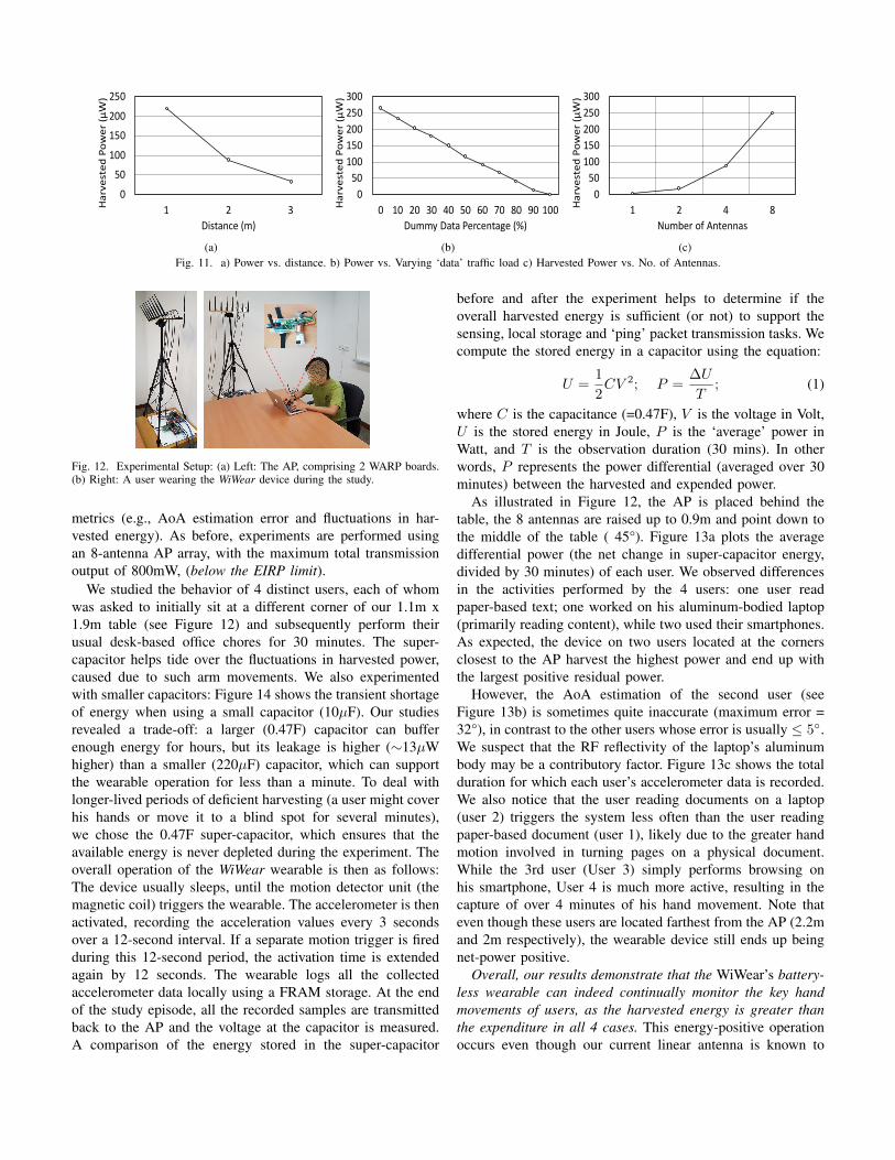
C. Energy harvesting vs. Distance
We next study how the efficiency of energy transfer dimin-ishes with an increasing AP-wearable distance. Figure 11ashows the harvested energy, as the distance is varied from1m-3m., with (azimuth=90°, elevation=0°). The results showthat, even at 3m, the AP can still transfer about 33µW tothe harvester. Given that our wearable with drains out only23µW (from the built-in 220µF supercapacitor) even when it
is continuously recording the accelerometer reading (withouttransmitting ‘ping’ packets), we see that our paradigm ofbeam-formed WiFi energy transfer is able to support theuninterrupted operation of the WiWear wearable essentiallyanywhere within a standard meeting room.
D. Energy harvesting vs. Background data
We next study how the energy transfer efficiency is affectedby the need for the AP’s power packet transmissions to co-exist with regular WiFi data packets. Note that our modifiedAP implements the 802.11 AP reference design (from Man-goComm [35]), and is thus able to provide data connectivityto regular WiFi clients. We study the sensitivity of efficiencyby varying the percentage of broadcasted IP (data) packets &power packets. Figure 11b shows that the harvested energydecreases quite linearly with the percentage of IP packets.When the AP exclusively transmits IP packets (100%), theharvested power is almost zero as the AP transmits suchpackets using only 1 antenna and usually at less than thehighest permitted power level. At the typical utilization (20%)observed on our campus WiFi network, WiWear appears tobe capable of harvesting 200µW, a 100-fold increase fromambient power levels.
E. Effect of Number of Antennas
We next vary the number of transmitting antennas in theWARP transmitter and study the impact on the harvestedpower (wearable-AP distance= 1 meter). Figure 11c plots theharvested power. Matching our intuition, a larger number ofantennas allows the transmission beamwidth to be thinner,thereby effectively increasing the density of the deliveredRF power. Interestingly, we observe that the angle at whichthe harvester gets the maximum energy differs a bit fromthe ground-truth, with the difference increasing from 5° to20°, when the number of antennas is reduced from 8 to 2,respectively. We suspect that this is due to the inevitable errorsin phase control, with the phase errors getting averaged outwhen the number of antennas is higher. However, in practicalenvironments, an overly thin beam may be counterproductiveas errors in AoA estimation (especially in more crowded envi-ronments) may cause the narrow RF beam to be misdirected,resulting in a very sharp drop in the power harvested.
VII. CONSTRAINED USER STUDIES
We now evaluate the performance of the WiWear prototype,under constrained user studies performed in our 3.5m x 4.5mmeeting room, set up to mimic a typical work environment.“Constrained” refers to the fact that the users are requested tostay within the meeting room during the study duration (30minutes) and perform their “normal” office activities, whilewearing the WiWear wearable device. Each user is, however,free to perform one or more activities of their choice (e.g.,typing on a laptop, taking short breaks and stretching, etc.).Unlike Section VI, the wearable is now subject to human-specific movement and resultant changes to its performance
2019 IEEE International Conference on Pervasive Computing and Communications (PerCom)
8
0
50
100
150
200
250
1 2 3Har
vest
ed P
ower
(µW
)
Distance (m)
(a)
050
100150200250300
0 10 20 30 40 50 60 70 80 90 100Har
vest
ed P
ower
(µW
)
Dummy Data Percentage (%)
(b)
050
100150200250300
1 2 4 8Har
vest
ed P
ower
(µW
)
Number of Antennas
(c)Fig. 11. a) Power vs. distance. b) Power vs. Varying ‘data’ traffic load c) Harvested Power vs. No. of Antennas.
Fig. 12. Experimental Setup: (a) Left: The AP, comprising 2 WARP boards.(b) Right: A user wearing the WiWear device during the study.
metrics (e.g., AoA estimation error and fluctuations in har-vested energy). As before, experiments are performed usingan 8-antenna AP array, with the maximum total transmissionoutput of 800mW, (below the EIRP limit).
We studied the behavior of 4 distinct users, each of whomwas asked to initially sit at a different corner of our 1.1m x1.9m table (see Figure 12) and subsequently perform theirusual desk-based office chores for 30 minutes. The super-capacitor helps tide over the fluctuations in harvested power,caused due to such arm movements. We also experimentedwith smaller capacitors: Figure 14 shows the transient shortageof energy when using a small capacitor (10µF). Our studiesrevealed a trade-off: a larger (0.47F) capacitor can bufferenough energy for hours, but its leakage is higher (∼13µWhigher) than a smaller (220µF) capacitor, which can supportthe wearable operation for less than a minute. To deal withlonger-lived periods of deficient harvesting (a user might coverhis hands or move it to a blind spot for several minutes),we chose the 0.47F super-capacitor, which ensures that theavailable energy is never depleted during the experiment. Theoverall operation of the WiWear wearable is then as follows:The device usually sleeps, until the motion detector unit (themagnetic coil) triggers the wearable. The accelerometer is thenactivated, recording the acceleration values every 3 secondsover a 12-second interval. If a separate motion trigger is firedduring this 12-second period, the activation time is extendedagain by 12 seconds. The wearable logs all the collectedaccelerometer data locally using a FRAM storage. At the endof the study episode, all the recorded samples are transmittedback to the AP and the voltage at the capacitor is measured.A comparison of the energy stored in the super-capacitor
before and after the experiment helps to determine if theoverall harvested energy is sufficient (or not) to support thesensing, local storage and ‘ping’ packet transmission tasks. Wecompute the stored energy in a capacitor using the equation:
U =1
2CV 2; P =
∆U
T; (1)
where C is the capacitance (=0.47F), V is the voltage in Volt,U is the stored energy in Joule, P is the ‘average’ power inWatt, and T is the observation duration (30 mins). In otherwords, P represents the power differential (averaged over 30minutes) between the harvested and expended power.
As illustrated in Figure 12, the AP is placed behind thetable, the 8 antennas are raised up to 0.9m and point down tothe middle of the table ( 45°). Figure 13a plots the averagedifferential power (the net change in super-capacitor energy,divided by 30 minutes) of each user. We observed differencesin the activities performed by the 4 users: one user readpaper-based text; one worked on his aluminum-bodied laptop(primarily reading content), while two used their smartphones.As expected, the device on two users located at the cornersclosest to the AP harvest the highest power and end up withthe largest positive residual power.
However, the AoA estimation of the second user (seeFigure 13b) is sometimes quite inaccurate (maximum error =32°), in contrast to the other users whose error is usually ≤ 5◦.We suspect that the RF reflectivity of the laptop’s aluminumbody may be a contributory factor. Figure 13c shows the totalduration for which each user’s accelerometer data is recorded.We also notice that the user reading documents on a laptop(user 2) triggers the system less often than the user readingpaper-based document (user 1), likely due to the greater handmotion involved in turning pages on a physical document.While the 3rd user (User 3) simply performs browsing onhis smartphone, User 4 is much more active, resulting in thecapture of over 4 minutes of his hand movement. Note thateven though these users are located farthest from the AP (2.2mand 2m respectively), the wearable device still ends up beingnet-power positive.
Overall, our results demonstrate that the WiWear’s battery-less wearable can indeed continually monitor the key handmovements of users, as the harvested energy is greater thanthe expenditure in all 4 cases. This energy-positive operationoccurs even though our current linear antenna is known to

0
50
100
150
200
250
User 1 User 2 User 3 User 4
Net
Pow
er (µ
W)
(a)
0
5
10
15
20
User 1 User 2 User 3 User 4
Ang
ular
Err
or (
°)
(b)
0
1
2
3
4
5
User 1 User 2 User 3 User 4
Act
ive
Tim
e (m
inut
es)
(c)Fig. 13. a) Net energy for 4 users (distance = {1.3, 1.4, 2.2, 2} meters). b) AoA error (4 users). c) Active accelerometer sensing period.
0
1000
2000
3000
1 15 29 43 57 71 85 99 113
127
141
155
169
Volta
ge (m
V)
Time (x10ms)Harvester Output Embedded system drain
Fig. 14. Time series of wearable voltage using 10µF small capacitor.
have very low gain near its poles; the use of better antennadesigns should further enhance the energy harvested.
VIII. DISCUSSION
While our results attest to the promise of WiWear, there are,however, several open issues to explore further.
Multi-AP Operation: In a practical campus or factoryenvironment, multiple APs are likely to ‘cover’ a specificlocation (e.g., in our campus, the number of APs overheard at atypical location is 5-6). This opens up additional possibilities.Clearly, as illustrated in EnergyBall [11], transmission ofsuitably beamformed transmissions on a common channel,along with careful phase control, can significantly increase theharvested energy. Alternately, each AP can transmit its ‘powerpackets’ on its own independent channel, thereby eliminatingthe difficult task of phase synchronization. However, the RFharvester module on the wearable must be enhanced ( [10]) to(a) allow the harvester to simultaneously support multiple res-onant AP frequencies, and (b) implement dynamic impedancematching (e.g., [36]).
Power vs. Throughput Tradeoffs: Our early results (Sec-tion VI.D) show that there is a tradeoff between the twoobjectives of data transfer and RF charging that remains tobe explored. Additional mechanisms may be used to optimizethis tradeoff: e.g., adjusting the schedule & duty cycle ofpower packet transmissions (e.g., by using multiple virtualqueues [37]) to avoid unacceptable loss or latency of datapackets or transmitting data packets at higher power (forenhanced energy harvesting).
Additional & Improved Energy Harvesting: The currentWiWear prototype uses a basic whip antenna for energy har-vesting (gain=2.1 dBi), whose performance degrades for largevalues of either the azimuthal or elevation angles. It is very
likely that alternative antenna designs (e.g., a metallic strip-based “patch antenna) can increase the harvested energy sig-nificantly (see [38]). Moreover, wearables may combine WiFienergy harvesting with other alternative harvesting techniques,such as ambient light, for significantly improved performance.Also, the magnetic trigger may be replaced with a kineticenergy harvester (such as the ones used in mechanical watches)that also harvests additional energy.
Other Application Domains & Paradigms: Our investi-gations focused on a single AP, with a single user in an office-like setting. Additional research is needed to apply the coreWiWear concept to other scenarios, such as (a) capturing keylocomotion and gesture-related behaviors (e.g., fall detection)of elderly inhabitants in smart homes; (b) operating staticsensors, deployed in industrial sites and warehouses.
IX. CONCLUSION
In this paper, we presented WiWear, an approach for bat-teryless sensing that uses beamforming of WiFi transmissionsto enable a wearable receiver to harvest more than 400µWof energy at a distance of 1 meter, and more than 30µWeven when the distance increases to 3 meters. WiWear couplesthis harvesting with smart event triggering, using a passivemotion detector, to duty cycle a full accelerometer-equippedwearable device whose instantaneous power drain (includingprocessor and wireless data interface) is more than 40 mW. Viameasurements and user studies performed in a representativeoffice setting, we see that WiWear can be a viable approach forbatteryless sensing of gestures. We also identified open issues,which we are currently addressing to develop a more robustand widely-applicable WiWear prototype.
ACKNOWLEDGMENT
This research is supported partially by Singapore Ministryof Education Academic Research Fund Tier 2 under researchgrant MOE2014-T2-1063, and by the National Research Foun-dation, Prime Ministers Office, Singapore under its IDMFutures Funding Initiative. All findings and recommendationsare those of the authors and do not necessarily reflect the viewsof the granting agency, or SMU. The authors also thank AritraChatterjee for his experimental investigations, which helpedrefine the WiWear system.

REFERENCES
[1] E. Thomaz, I. Essa, and G. D. Abowd, “A practical approach forrecognizing eating moments with wrist-mounted inertial sensing,” inProceedings of the 2015 ACM International Joint Conference on Perva-sive and Ubiquitous Computing, ser. UbiComp ’15. ACM, 2015, pp.1029–1040.
[2] A. Parate, M.-C. Chiu, C. Chadowitz, D. Ganesan, and E. Kalogerakis,“Risq: Recognizing smoking gestures with inertial sensors on a wrist-band,” in Proceedings of the 12th Annual International Conference onMobile Systems, Applications, and Services, ser. MobiSys ’14. ACM,2014, pp. 149–161.
[3] E. Ertin, N. Stohs, S. Kumar, A. Raij, M. al’Absi, and S. Shah,“Autosense: Unobtrusively wearable sensor suite for inferring the onset,causality, and consequences of stress in the field,” in Proceedings ofthe 9th ACM Conference on Embedded Networked Sensor Systems, ser.SenSys ’11. ACM, 2011, pp. 274–287.
[4] B. Campbell and P. Dutta, “An energy-harvesting sensor architectureand toolkit for building monitoring and event detection,” in Proceedingsof the 1st ACM Conference on Embedded Systems for Energy-EfficientBuildings, ser. BuildSys ’14. ACM, 2014.
[5] A. Hande, T. Polk, W. Walker, and D. Bhatia, “Indoor solar energyharvesting for sensor network router nodes,” Microprocess. Microsyst.,vol. 31, no. 6, Sep. 2007.
[6] B. Campbell, B. Ghena, and P. Dutta, “Energy-harvesting thermoelectricsensing for unobtrusive water and appliance metering,” in Proceedingsof the 2Nd International Workshop on Energy Neutral Sensing Systems,ser. ENSsys ’14. ACM, 2014.
[7] K. Ryokai, P. Su, E. Kim, and B. Rollins, “Energybugs: Energy harvest-ing wearables for children,” in Proceedings of the SIGCHI Conferenceon Human Factors in Computing Systems, ser. CHI ’14. New York,NY, USA: ACM, 2014.
[8] X. Liu, “Qi standard wireless power transfer technology developmenttoward spatial freedom,” IEEE Circuits and Systems Magazine, vol. 15,no. 2, pp. 32–39, Secondquarter 2015.
[9] D. J. Yeager, P. S. Powledge, R. Prasad, D. Wetherall, and J. R. Smith,“Wirelessly-charged uhf tags for sensor data collection,” in 2008 IEEEInternational Conference on RFID, April 2008.
[10] V. Talla, B. Kellogg, B. Ransford, S. Naderiparizi, S. Gollakota, and J. R.Smith, “Powering the next billion devices with wi-fi,” in Proceedingsof the 11th ACM Conference on Emerging Networking Experiments andTechnologies. ACM, 2015, p. 4.
[11] X. Fan, H. Ding, S. Li, M. Sanzari, Y. Zhang, W. Trappe, Z. Han,and R. E. Howard, “Energy-ball: Wireless power transfer for batterylessinternet of things through distributed beamforming,” Proc. ACM Interact.Mob. Wearable Ubiquitous Technol., vol. 2, no. 2, Jul. 2018.
[12] J. Hester and J. Sorber, “The future of sensing is batteryless, intermit-tent, and awesome,” in Proceedings of the 15th ACM Conference onEmbedded Network Sensor Systems, ser. SenSys ’17. ACM, 2017.
[13] V. H. Tran, A. Misra, J. Xiong, and N. Hirunima, “Can wifi beamformingsupport an energy-harvesting wearable?” in Proceedings of the FifthACM International Workshop on Energy Harvesting and Energy-NeutralSensing Systems, ser. ENSsys’17. ACM, 2017.
[14] J. Xiong and K. Jamieson, “Arraytrack: A fine-grained indoor locationsystem,” in 10th Usenix Symposium on Networked Systems Design andImplementation. USENIX, 2013.
[15] K. Lin, J. Yu, J. Hsu, S. Zahedi, D. Lee, J. Friedman, A. Kansal,V. Raghunathan, and M. Srivastava, “Heliomote: Enabling long-livedsensor networks through solar energy harvesting,” in Proceedings of the3rd International Conference on Embedded Networked Sensor Systems,ser. SenSys ’05. ACM, 2005.
[16] “Solepower smart boots,” http://www.solepowertech.com/smartboots/,2018, accessed: 2018-04-04.
[17] G. Xu, Y. Yang, Y. Zhou, and J. Liu, “Wearable thermal energy harvesterpowered by human foot,” Frontiers in Energy, vol. 7, no. 1, 2013.
[18] J. Hester and J. Sorber, “Flicker: Rapid prototyping for the batterylessinternet-of-things,” in Proceedings of the 15th ACM Conference onEmbedded Network Sensor Systems, ser. SenSys ’17. ACM, 2017.
[19] A. P. Sample, D. J. Yeager, P. S. Powledge, A. V. Mamishev, andJ. R. Smith, “Design of an rfid-based battery-free programmable sensingplatform,” IEEE Transactions on Instrumentation and Measurement,vol. 57, no. 11, pp. 2608–2615, Nov 2008.
[20] W. Huang, H. Chen, Y. Li, and B. Vucetic, “On the performance of multi-antenna wireless-powered communications with energy beamforming,”IEEE Transactions on Vehicular Technology, vol. 65, no. 3, pp. 1801–1808, 2016.
[21] L. Liu, R. Zhang, and K.-C. Chua, “Multi-antenna wireless poweredcommunication with energy beamforming,” IEEE Transactions on Com-munications, vol. 62, no. 12, pp. 4349–4361, 2014.
[22] D. Vasisht, S. Kumar, and D. Katabi, “Decimeter-level localizationwith a single wifi access point,” in Proceedings of the 13th UsenixConference on Networked Systems Design and Implementation, ser.NSDI’16. USENIX Association, 2016, pp. 165–178.
[23] Q. Pu, S. Gupta, S. Gollakota, and S. Patel, “Whole-home gesturerecognition using wireless signals,” in Proceedings of the 19th annualinternational conference on Mobile computing & networking. ACM,2013, pp. 27–38.
[24] D. Bharadia, E. McMilin, and S. Katti, “Full duplex radios,” in ACMSIGCOMM Computer Communication Review, vol. 43, no. 4. ACM,2013, pp. 375–386.
[25] M. Jain, J. I. Choi, T. Kim, D. Bharadia, S. Seth, K. Srinivasan, P. Levis,S. Katti, and P. Sinha, “Practical, real-time, full duplex wireless,” inProceedings of the 17th annual international conference on Mobilecomputing and networking. ACM, 2011, pp. 301–312.
[26] X. Li, D. Zhang, Q. Lv, J. Xiong, S. Li, Y. Zhang, and H. Mei,“Indotrack: Device-free indoor human tracking with commodity wi-fi,”Proc. ACM Interact. Mob. Wearable Ubiquitous Technol., vol. 1, no. 3,Sep. 2017.
[27] R. Schmidt, “Multiple emitter location and signal parameter estimation,”IEEE transactions on antennas and propagation, vol. 34, no. 3, pp. 276–280, 1986.
[28] “Ultra-low-power arm cortex-m0+ mcu with 64 kbytes flash, 32 mhzcpu, usb, lcd,” http://www.st.com/en/microcontrollers/stm32l053r8.html,2018, accessed: 2018-04-08.
[29] E. K. Antonsson and R. W. Mann, “The frequency content of gait,”Journal of biomechanics, vol. 18, no. 1, pp. 39–47, 1985.
[30] P. Miao, P. Mitcheson, A. Holmes, E. Yeatman, T. Green, and B. Stark,“Mems inertial power generators for biomedical applications,” Microsys-tem Technologies, vol. 12, no. 10-11, pp. 1079–1083, 2006.
[31] E. M. Yeatman, P. D. Mitcheson, and A. S. Holmes, “Micro-engineereddevices for motion energy harvesting,” in Electron Devices Meeting,2007. IEDM 2007. IEEE International. IEEE, 2007, pp. 375–378.
[32] “Warp wireless open-access research platform,”https://mangocomm.com/products/kits/warp-v3-kit, 2017, accessed:2017-08-25.
[33] C. T. Chou, A. Misra, and J. Qadir, “Low-latency broadcast in multiratewireless mesh networks,” IEEE Journal on Selected Areas in Commu-nications, vol. 24, no. 11, pp. 2081–2091, 2006.
[34] S. Sen, J. Xiong, R. Ghosh, and R. R. Choudhury, “Link layer multicas-ting with smart antennas: No client left behind,” in Network Protocols,2008. ICNP 2008. IEEE International Conference on. IEEE, 2008, pp.53–62.
[35] “802.11 reference design for warp v3,”https://warpproject.org/trac/wiki/802.11, 2018, accessed: 2018-09-29.
[36] C. Felini, M. Merenda, and F. G. D. Corte, “Dynamic impedancematching network for rf energy harvesting systems,” in 2014 IEEE RFIDTechnology and Applications Conference (RFID-TA), Sept 2014.
[37] E. Rozner, V. Navda, R. Ramjee, and S. Rayanchu, “Napman: Network-assisted power management for wifi devices,” in Proceedings of the 8thInternational Conference on Mobile Systems, Applications, and Services,ser. MobiSys ’10. ACM, 2010.
[38] S. J. Chen, T. Kaufmann, and C. Fumeaux, “Wearable textile microstrippatch antenna for multiple ism band communications,” in 2013 IEEEAntennas and Propagation Society International Symposium (APSURSI),July 2013.
2019 IEEE International Conference on Pervasive Computing and Communications (PerCom)
11