wiring for 32' marinette - .:: geocities.ws€¦ · nothing is grounded directly to the hull....
TRANSCRIPT

Wiring Diagram for 32' Marinette Flybridge Sedanwith conversion to twin Perkins diesels
I have made every attempt to ensure that these drawings are accurate but there is no
guarantee that the drawings are correct or that they are suitable for any purpose.
This wiring represents my current view of how my boat should be wired, based on my
experience in aerospace and naval engineering. This is a work in progress and I would be
happy for comments from anyone.
Doug Rose

Conventions:
Line widths reflect the size of the wire used in the circuit. The key is shown on the
'Primary' drawing.
All wires are shown going to the physical terminal to which they are actually wired, so the
boat “looks” like the diagram.
Connections to other drawings may be shown for clarity, as called out on the print. Those
portions of a drawing already shown elsewhere are dotted. The actual circuit appears
only once in solid.
Philosophy:
The wire network consists of cables (of several wires each) that connect terminal blocks
located at each important station, and shorter wires from the terminal blocks to individual
loads. Installation effort is reduced when each cable is pulled as a unit.
Terminal blocks have the same configuration as the accessory (eyebrow) panel breakers
for clarity. Troubleshooting and repair are easier when the terminal block function
assignments are the same at each station. This means that some terminals will be
unused.
The wiring for each engine is separate from and not connected to the other, and the
engine circuits are separate from the ship's circuits. This increases reliability, isolates
failures, and speeds troubleshooting. The only connection common among the three
independent systems is the ground plate.
Similarly, the 'port' accessories, those with breakers on the port half of the accessory
panel, are a separate circuit from the 'starboard' accessories. The two circuits are
common only at the 'ship's power' terminals.
The exception to the engine circuit separation is the provision for starting either engine
from either battery, as shown in 'Primary'. When the switches are in normal position as
shown in 'Primary', the engine circuits are separate.
Every attempt has been made to avoid “daisy chaining”, the practice of running power or
ground from load to load. Rather, loads are each wired to common terminals. This avoids
the “Christmas tree effect” when troubleshooting.
Returns are provided for each load, and for each circuit. Each ground/return wire parallels
its companion positive wire throughout until the current returns to the ground plate.
Nothing is grounded directly to the hull. All returns end at the ground plate, which is
connected to the hull through a 1 milliohm shunt, used for troubleshooting.
Notes:
A number of suppliers offer voltage-sensitive automatic charging relays that short batteries
together when either one sees charging voltage. These would make a good substitute for
the diode bank shown in 'Charging'.

14 AWG
10 AWG
2 AWG
2/0 AWG
on another page
GROUND PLATE
50 50
Inverter
80 50 50 50 50
Volts"3"
Volts"4"
Ship's Power
Ship'sbatteryswitch
Top of lower steering station kickpanel
Lower steering station kickpanel
Either side of lower wheel
Ship's voltmetersand loadmeter
Behind lower steering station kickpanel
EngineBreaker
EngineBreaker
Anch
or W
inch
Stbd
Acce
ssor
y Po
wer
Port
A
cces
sory
Pow
er
Head
Ship's Breakers
Top of lowersteering stationkickpanel
1 mOhm
Ship's Hull
Battery 1
Battery 4
Battery 3
Battery 2
PortBatterySwitch
StbdBatterySwitch
Port Engine Block Stbd Engine Block
PortAlternator
StbdAlternator
Primary
Portstarter
Stbdstarter
1 2
COM
SHUNT
1 2
COM
SHUNT
1 2
COM
SHUNT
see 'Charging'
see 'Charging'
see 'Charging'
see 'Charging'
1 mV/A1 mV/A
GROUNDHULL
Test Jacks
1 mV/A1 mV/A
9/25/08
Port Charge
BAT
ALT
RTN
START
TEMP
TACH
BAT
ALT
RTN
START
TEMP
TACH
Port EngineTerminal Block
Stbd EngineTerminal Block
see 'Engine Cabling'
see 'Engine Cabling'
Port EngineBlock
Note:
Each engine control panel is powered through the engine breaker, and returns to the engine block at the alternator.
The engine block returns to the battery through a starter mounting bolt.
Engi
ne
B
ilge
Pum
p
Stbd Charge
Portstartrelay
Stbdstartrelay
StopSolenoid
StopSolenoid
See EngineSchematicfor start relaycoil circuit.
ControlsBreaker5
ControlsBreaker5

Charging
9/25/08
Battery 1
Battery 4
Battery 3
Battery 2
see 'Primary'
see 'Primary'
see 'Primary'
AC to DCDual Output
FerroresonantBattery Charger
15 Adc
RTN 1 2
PPL
Bootstrap Diode
OUT
FRAME
TACH
REGULATOR
SENSE
Port EngineTerminal Block
Port Engine Block
Port Alternator
PPL
Bootstrap Diode
OUT
FRAME
TACH
REGULATOR
SENSE
Stbd Engine Block
Stbd Alternator
GROUND PLATE
Solar Battery85 W
Lower Station Ship's Terminal Block
Engine CompartmentBulkhead Forward
BLU
YEL/
GRN
BRN ORN O
RN
BAT
ALT
RTN
START
TEMP
TACH
PRES
IGN
ALARM
STOP
UPPER
FUEL
see Engine Cabling
Stbd EngineTerminal Block
see Engine Cabling
BAT
ALT
RTN
START
TEMP
TACH
PRES
IGN
ALARM
STOP
UPPER
FUEL
see 'Primary'
see 'Primary'
Note: Alternators are not self-exciting, and field power is internally connected to OUT. The Bootstrap Diode provides power to the field from the ignition until alternator power is available at OUT.
Note: Alternator regulated output is 14.6 Vdc. After 2 diodes, the charging voltage is 13.6 Vdc, which is the correct charging voltage for the AGM batteries.
PortBatterySwitch
StbdBatterySwitch
1 2
COM
1 2
COM
EngineBreaker
EngineBreaker
Charging Connector Port Aft of Cabin TopUP
WIN
CH DN RTN
SOLA
R CE
LL
SOLA
R RT
N
Behind Accessory Panel+-
Port Engine Block
Stbd Engine Block
Lower Panel
Generator
0.47/5 0.47/5

Future Charging usingVoltage Sensitive Relays
9/25/08
Battery 1
Battery 4
Battery 3
Battery 2
see 'Primary'
see 'Primary'
see 'Primary'
AC to DCDual Output
FerroresonantBattery Charger
15 Adc
RTN 1 2
PPL
Bootstrap Diode
OUT
FRAME
TACH
REGULATOR
SENSE
Port EngineTerminal Block
Port Engine Block
Port Alternator
PPL
Bootstrap Diode
OUT
FRAME
TACH
REGULATOR
SENSE
Stbd Engine Block
Stbd Alternator
GROUND PLATE
Solar Battery85 W
Lower Station Ship's Terminal Block
Engine CompartmentBulkhead Forward
BLU
YEL/
GRN
BRN ORN O
RN
BAT
ALT
RTN
START
TEMP
TACH
PRES
IGN
ALARM
STOP
UPPER
FUEL
see Engine Cabling
Stbd EngineTerminal Block
see Engine Cabling
BAT
ALT
RTN
START
TEMP
TACH
PRES
IGN
ALARM
STOP
UPPER
FUEL
see 'Primary'
see 'Primary'
Note: Alternators are not self-exciting, and field power is internally connected to OUT. The Bootstrap Diode provides power to the field from the ignition until alternator power is available at OUT.
Note: Alternator regulated output is 14.6 Vdc. After 2 diodes, the charging voltage is 13.6 Vdc, which is the correct charging voltage for the AGM batteries.
PortBatterySwitch
StbdBatterySwitch
1 2
COM
1 2
COM
EngineBreaker
EngineBreaker
Charging Connector Port Aft of Cabin Top
SOLA
R CE
LL
SOLA
R RT
N
Behind Accessory Panel+-
Port Engine Block
Stbd Engine Block
Battery Combiner
Battery Combiner
Ship'sbatteryswitchLower
steering station kickpanel 1 2
COM
SHUNT

Ship's Power Distribution
9/25/08
80 50 50 50 50
Ship's Power
Top of lower steering station kickpanel
Anch
or W
inch
Stbd
Acce
ssor
y Po
wer
Port
A
cces
sory
Pow
er
Spar
e
Head
Ship's Breakers
Top of lowersteering stationkickpanel
Upper Station Ship's Terminal BlockBehind upper steering station kickpanel
Marinette Accessory Panel Terminal BlockBehind Marinette Accessory Panel
Lower Station Ship's Terminal BlockBehind access panel on bulkhead aft of dinette
Not ShownTerminals are powered thru circuit breakers in
Accessory PanelReturns go to appropriate side of Accessory Panel Terminal Blockvia return busses at lower station
N/C
N/C
ACC. 1
SPARE
NAV. LIGHTS
ANCHOR LIGHT
ACC. 2
SPARE
N/C
ENGINE ALARM
TRIM TAB
SPARE
N/C
N/C
BLOWER
SPARE
CABIN LIGHTS
DEPTH SOUNDER
N/C
SPARE
SEARCH LIGHT
HORN
RADIO
SPARE
WIPER
WIPER
ACC. 1
NAV. LIGHTS
ANCHOR LIGHT
ACC. 2
SHOWER
ENGINE ALARM
TRIM TAB
PUMP FWD
PUMP AFT
BLOWER
CABIN LIGHTS
DEPTH SOUNDER
WATER SYSTEM
SEARCH LIGHT
HORN
RADIO
see 'Primary'
HEAD
Cockpit DC outlets
RELAYBOX
WINCHMOTOR
See Anchor Winch
UpperControls
LowerControls
ForedeckControls
Note: Power (RED) and Return (YEL) are routedtogether to eliminate 'ground loops'. Doubleconductor cable ispreferred

FIELD
18 VDC@ 100 A
SHUNT1 mV / A
+20 VDC
CHARGE
-
CHARGINGAMPS
++S
-S
GROUND PLATE
+
Generator
Adjust engine fuel for 100 A output
ROTOR
Internal Resistance (fully charged): .0025 ohmsCapacity: 75 Ah (C/20) Reserve Capacity: BCI: 155 minutes (25 amp discharge, 80°F (26.7°C), to 10.5 volts cut-off)
CONTROL CIRCUIT: => Starts engine when V3 or V4 drops to 11.5 Vdc => Stops engine when V3 or V4 reaches 14.7 Vdc => Stops engine if no oil pressure for 15 seconds => Stops engine on engine over temperature => Stops engine on battery over temperature
see 'Primary'
Battery 1
Battery 4
Battery 3
Battery 2
see 'Primary' see 'Primary' see 'Primary' see 'Primary'
0.2 ohm dc
1.6 ohm dc
There is no current control. The engine fuel lever is adjusted manually to obtain 100 A. of charge, and is then mechanically locked.

Engine Cabling
9/25/08
BAT
RTN
TMP
PRES
ALARM
UPPER
ALT
START
TACH
IGN
STOP
FUEL
BAT
ALT
RTN
STAR
T
TEM
P
TACH
PRES
IGN
ALAR
M
STO
P
UPPE
R
FUEL
TACH
TEM
P
STAR
T
RTN
ALT
BAT
FUEL
UPPE
R
STO
P
ALAR
M
IGN
PRES
Port Upper Steering Station
Mounted to bottom of metal engine panel
Stbd Upper Steering Station
12 X 24 AWGLength tbd
12 X 24 AWGLength tbd
12 X 24 AWGLength tbd
12 X 24 AWGLength tbd
12 X 24 AWGLength tbd
12X 24 AWGLength tbd
Port EngineTerminal Block
Stbd EngineTerminal Block
Aft top of Port Engine Aft top of
Stbd Engine`
Spares:EGT, 2 wiresAlt I, 2 wiresSP, 2 wires
EGT +
EGT -
I alt +
I alt -
spare
spare
Spares:EGT, 2 wiresAlt I, 2 wiresSP, 2 wires
ORN
YEL
GRY
VIO
GRN
PNK
RED
ORN
BLK
YEL
TAN
GRY BLU
VIO
WTE
GRN
BRN
PNK RED
ORN
BLK
YEL
TAN
GRY
BLU
VIO
WTE
GRN
BRN
PNK
RED
BLK
TAN
BLU
WTE
BRN
EGT +
EGT -
I alt +
I alt -
spare
spare
STBD
FOR'D
RED
BLK
TAN
BLU
WTE
BRN
ORN
YEL
GRY
VIO
GRN
PNK
BAT
RTN
TMP
PRES
ALARM
UPPER
ALT
START
TACH
IGN
STOP
FUEL
ORN
YEL
GRY
VIO
GRN
PNK
RED
BLK
TAN
BLU
WTE
BRN
STBD
FOR'D
RED
BLK
TAN
BLU
WTE
BRN
ORN
YEL
GRY
VIO
GRN
PNK
BAT
RTN
TMP
PRES
ALARM
UPPER
ALT
START
TACH
IGN
STOP
FUEL
ORN
YEL
GRY
VIO
GRN
PNK
RED
BLK
TAN
BLU
WTE
BRN
BAT
RTN
TMP
PRES
ALARM
UPPER
ALT
START
TACH
IGN
STOP
FUEL
ORN
YEL
GRY
VIO
GRN
PNK
RED
BLK
TAN
BLU
WTE
BRN
BLOCK
SHIELD
BLOCK
SHIELD
Future wiring for Exhaust Gas Temperature Probes and for Charging Current

______STBD ALARM
Engine Schematic
9/25/08
ALT
START
TACH
IGN
STOP
FUEL
Port or Stbd Upper Steering Station
Port or Stbd Engine Terminal Block
BAT
ALT
RTN
STAR
TTE
MP
TACH
PRES
IGN
ALAR
MST
OP
UPPE
RFU
EL
Port or Stbd Lower Steering Station
-+
-+-
+-
+
VOLTSIGNITIONSWITCH
WATERTEMPERATURE
TACHOMETEROILPRESSURE
ALARMLAMP
(STOP) FUEL
OILPRESSURE
TACHOMETER
WATERTEMPERATURE
ALARMLAMP
ALARMHORN
(ENGINE START)
(ENGINE STOP)
TAN
ALARMHORN
-+
BATACC ST
IGN
-+
PNKBLUPPLGRYTAN
VIO
OUT
FRAME
TACH
REGULATOR
SENSE
Engine Block
BLOCK
BLOCK
STARTERNEUTRALSWITCH
LowOil
PressNC
HighWaterTempNO
StopSolenoid
50
BAT
RTN
TMP
PRESS
ALARM
UPPER
Battery Switch Common
Oil PressureSender
Fuel Level Sensortop of fuel tankWater
TempSender
see 'Primary'
see Charging see 'Primary'
see 'Engine Cabling'
see 'Engine Cabling'
see 'Engine Cabling'
NEUTRALINDICATOR
WTE
RED
NEUTRALINDICATOR WTE
StartRelay
Note: IGN powers upper steering station ACC position enables lower station only
ControlsBreaker 3
BLOCK BLOCK
STBD
ALT
START
TACH
IGN
STOP
FUEL
BAT
RTN
TMP
PRESS
ALARM
UPPER -+
VOLTS
-+
-+
-+
GRY
PPLBLU
PORT IGN
______ PORT ALARM
STBD IGN
Single alarm lamp for upper station
ALARMLAMP
HighExhaust
TempNO
BLOCK
StartRelay
StopRelay
Forward
Sta
rbor
d
Each Engine
51/3
51/3
see 'Primary'
mosaic immob
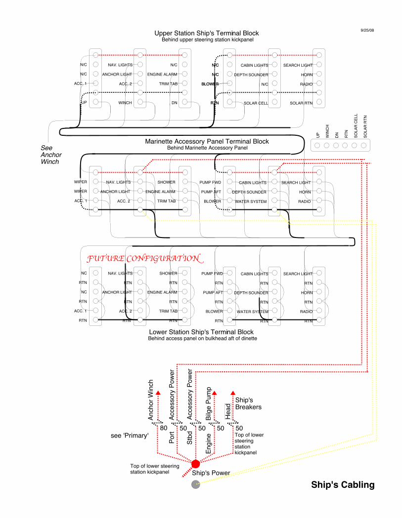
Ship's Cabling
9/25/08
80 50 50 50 50
Ship's PowerTop of lower steering station kickpanel
Anch
or W
inch
Stbd
Acce
ssor
y Po
wer
Port
A
cces
sory
Pow
er
Engi
ne
B
ilge
Pum
p
Head
Ship's Breakers
Top of lowersteering stationkickpanel
Upper Station Ship's Terminal BlockBehind upper steering station kickpanel
Marinette Accessory Panel Terminal BlockBehind Marinette Accessory Panel
Lower Station Ship's Terminal BlockBehind access panel on bulkhead aft of dinette
N/C
N/C
ACC. 1
UP
NAV. LIGHTS
ANCHOR LIGHT
ACC. 2
WINCH
N/C
ENGINE ALARM
TRIM TAB
DN
N/C
N/C
BLOWER
RTN
CABIN LIGHTS
DEPTH SOUNDER
N/C
SOLAR CELL
SEARCH LIGHT
HORN
RADIO
SOLAR RTN
WIPER
WIPER
ACC. 1
NAV. LIGHTS
ANCHOR LIGHT
ACC. 2
SHOWER
ENGINE ALARM
TRIM TAB
PUMP FWD
PUMP AFT
BLOWER
CABIN LIGHTS
DEPTH SOUNDER
WATER SYSTEM
SEARCH LIGHT
HORN
RADIO
NC
RTN
NC
RTN
ACC. 1
RTN
NAV. LIGHTS
RTN
ANCHOR LIGHT
RTN
ACC. 2
RTN`
SHOWER
RTN
ENGINE ALARM
RTN
TRIM TAB
RTN
PUMP FWD
RTN
PUMP AFT
RTN
BLOWER
RTN
CABIN LIGHTS
RTN
DEPTH SOUNDER
RTN
WATER SYSTEM
RTN
SEARCH LIGHT
RTN
HORN
RTN
RADIO
RTN
see 'Primary'
UP WIN
CH
DN RTN
SOLA
R CE
LL
SOLA
R RT
N
N/C
N/C
BLOWER
RTN
FUTURE CONFIGURATION
See Anchor Winch

Ship's Cabling
9/25/08
80 50 50 50 50
Ship's PowerTop of lower steering station kickpanel
Anch
or W
inch
Stbd
Acce
ssor
y Po
wer
Port
A
cces
sory
Pow
er
Engi
ne
B
ilge
Pum
p
Head
Ship's Breakers
Top of lowersteering stationkickpanel
Upper Station Ship's Terminal BlockBehind upper steering station kickpanel
Marinette Accessory Panel Terminal BlockBehind Marinette Accessory Panel
Lower Station Ship's Terminal BlockBehind access panel on bulkhead aft of dinette
N/C
N/C
ACC. 1
UP
NAV. LIGHTS
ANCHOR LIGHT
ACC. 2
WINCH
N/C
ENGINE ALARM
TRIM TAB
DN
N/C
N/C
BLOWER
RTN
CABIN LIGHTS
DEPTH SOUNDER
N/C
SOLAR CELL
SEARCH LIGHT
HORN
RADIO
SOLAR RTN
WIPER
WIPER
ACC. 1
NAV. LIGHTS
ANCHOR LIGHT
ACC. 2
SHOWER
ENGINE ALARM
TRIM TAB
PUMP FWD
PUMP AFT
BLOWER
CABIN LIGHTS
DEPTH SOUNDER
WATER SYSTEM
SEARCH LIGHT
HORN
RADIO
BROWN RUNNING LIGHTS
RED ANCHOR
ORANGE/WHITE ALARM
BLUE SHOWER PUMP
RED TRIM TABS
BLK RADIO
AUTO BP
AUTO BP
BLUE HORN
GREEN BLOWER
BLACK BILGE PUMP
ORANGE SPOTLIGHT
RED DEPTH SOUNDER
GREEN WATER PUMP
YELLOW CABIN LIGHTS
AUTO BP DOWN
PB AFT
see 'Primary'
UP WIN
CH
DN RTN
SOLA
R CE
LL
SOLA
R RT
N
BLU
GRN
BLK
ORN
RED
GRN
YEL
BLK
RED
BRN
RED
ORN
BLU
GRN
RED
WTE
BRN
RED
RED
BLK
RED
3
3
BLU
GRN
BLK
GRN
YEL
As-is Configuration RTNbus
See Anchor Winch
80 50 50 50 50
Ship's PowerTop of lower steering station kickpanel
Anch
or W
inch
Engi
ne
B
ilge
Pum
p
Head
Ship's Breakers
Top of lowersteering stationkickpanel
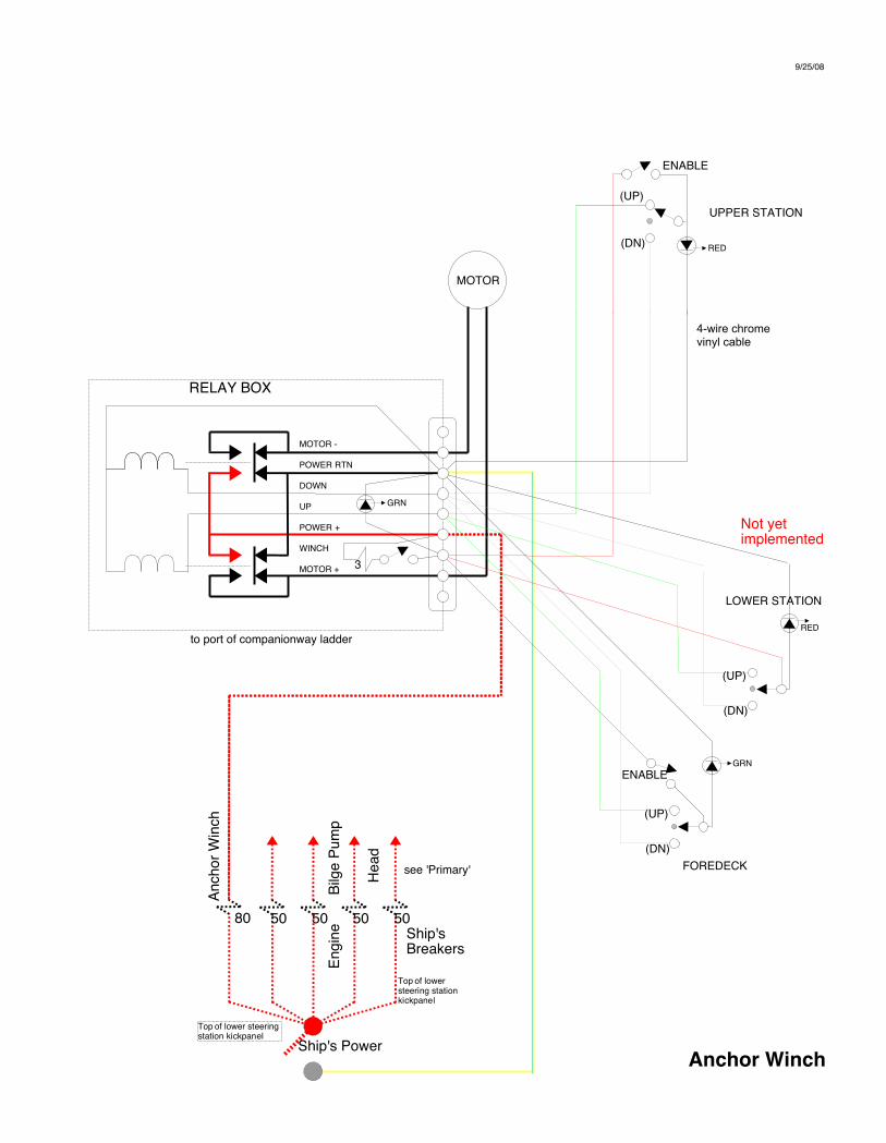
Anchor Winch
9/25/08
MOTOR -
POWER RTN
DOWN
UP
POWER +
WINCH
MOTOR + 3
GRN
RED
(UP)
(DN)
ENABLE
RED
(UP)
(DN)
GRN
(UP)
(DN)
ENABLE
FOREDECK
LOWER STATION
UPPER STATION
MOTOR
see 'Primary'
RELAY BOX
to port of companionway ladder
Not yet implemented
4-wire chromevinyl cable

Accessory Panel
9/25/08
80 50 50 50 50
Ship's Powersee Primary
Anch
or W
inch
Stbd
Acce
ssor
y Po
wer
Port
A
cces
sory
Pow
er
Engi
ne
B
ilge
Pum
p
Head
Ship's Breakers
Top of lowersteering stationkickpanel
WIPER
WIPER
ACC. 1
NAV. LIGHTS
ANCHOR LIGHT
ACC. 2
SHOWER
ENGINE ALARM
TRIM TAB
PUMP FWD
PUMP AFT
BLOWER
CABIN LIGHTS
DEPTH SOUNDER
WATER SYSTEM
SEARCH LIGHT
HORN
RADIO
WIPER
WIPER
ACC. 1
10
10
Marinette Accessory Panel Terminal BlockBehind Marinette Accessory Panel, lower steering station
15
NAV. LIGHTS
ANCHOR LIGHT
ACC. 2
10
10
15
SHOWER
ENGINE ALARM
TRIM TAB
10
10
20
PUMP FWD.
PUMP AFT.
BLOWER
10
10
10
CABIN LIGHTS
DEPTH SOUNDER
WATER SYSTEM
20
10
15
SEARCH LIGHT
HORN
RADIO
15
20
FOREBILGE
AFTBILGE
(HORN)
PANELLIGHT
see 'Ship's Cabling'

Accessory Loads
9/25/08
Marinette Accessory Panel Terminal BlockBehind Marinette Accessory Panel, lower steering station
Lower Station Ship's Terminal BlockBehind access panel on bulkhead aft of dinette
SEARCHLIGHT
portwipermotor
stbdwipermotor
WIPER
WIPER
ACC. 1
NAV. LIGHTS
ANCHOR LIGHT
ACC. 2
SHOWER
ENGINE ALARM
TRIM TAB
PUMP FWD
PUMP AFT
BLOWER
CABIN LIGHTS
DEPTH SOUNDER
WATER SYSTEM
SEARCH LIGHT
HORN
RADIO
WIPER
WIPER
ACC. 1
UP
NAV. LIGHTS
ANCHOR LIGHT
ACC. 2
WINCH
SHOWER
ENGINE ALARM
TRIM TAB
DN
PUMP FWD
PUMP AFT
BLOWER
RTN
CABIN LIGHTS
DEPTH SOUNDER
WATER SYSTEM
SOLAR CELL
SEARCH LIGHT
HORN
RADIO
SOLAR RTN
motor
WIPER
WIPER
ACC. 1
UP
NAV. LIGHTS
ANCHOR LIGHT
ACC. 2
WINCH
SHOWER
ENGINE ALARM
TRIM TAB
DN
PUMP FWD
PUMP AFT
BLOWER
WINCH RTN
CABIN LIGHTS
DEPTH SOUNDER
WATER SYSTEM
SOLAR CELL
SEARCH LIGHT
HORN
RADIO
SOLAR RTN
UpperCompass
Stern
Port Nav
Stbd Nav
LowerCompass
cockpitarealights
Trim Tab Pump Assy
Center Transom
+
-
SWIT
CH
+12
VDC
RTN
SWIT
CH
+12
VDC
RTN
BILGEPUMP
FLOAT
SUMPPUMP
FLOAT Under forward cabin sole
WATERPUMP
See Charging WATER
-+
WATER SENSOR
+-
S S
Between lower engine controls
Top of water tank
BILGEPUMP
FLOAT
SWIT
CH
+12
VDC
RTN
SWIT
CH
+12
VDC
RTN
Engine room bilge
HORN
See Charging
See Anchor Winch
BILGEPUMP
FLOAT Aft bilge
VHF radio
see 'Ship's Cabling'
Upper Station Ship's Terminal BlockBehind upper steering station kickpanel
see 'Ship's Cabling'
see 'Ship's Cabling'
Stbd Saloon Overhead
Port Saloon Overhead
OverheadSwitches
(ON)
DepthSounder
Anchor
UP
WIN
CH DN RTN
SOLA
R CE
LL
SOLA
R RT
N
See 'Charging'
Forward
(ON)
Panel stbd ofupper helm
Panel port ofupper helm
LIGHT ACC
Betweenenginesbeneathsole

Emergency Bilge Pump
9/25/08
Emergency Pump Circuit
FLOAT
mounted high in bilge
see Charging
SWIT
CH
+12
VDC
RTN
SWIT
CH
+12
VDC
RTN
BILGEPUMP
FLOAT
SUMPPUMP
FLOAT Under forward cabin sole
see Accessory Loads
BILGEPUMP
FLOAT
SWIT
CH
+12
VDC
RTN
SWIT
CH
+12
VDC
RTN
Engine room bilge BILGE
PUMP
FLOAT Aft bilge
see Accessory Loads
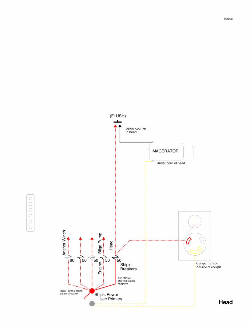
80 50 50 50 50
Ship's Power see Primary
Top of lower steering station kickpanel
Anch
or W
inch
Engi
ne
B
ilge
Pum
p
Head
Ship's Breakers
Top of lowersteering stationkickpanel
Head
9/25/08
(FLUSH)
MACERATOR
Under bowl of head
below counterin head
Cockput 12 VdcAft side of cockpit

AC
20
20
20
20
20
20
20
20
0-30 Aac
~ ~Frequency to
Voltage converter + -
Hertz
Marinette AC Panel
AC Voltage
ACFrequency
Shore Voltage50-250
Vac
H1
H2H3
H4X1
X2X3
X4
BLKWTE
GRN
110 Vac
ac GND
110 Vac
H1H2
H3
H4X1
X2X3X4
3030
Ship's ac neutral
BLK
WTE
Invertersee 'Primary'
20Kohm / 1W
see 'Primary'
WTE
fused shore hotfused shore rtn
SHOREVOLTAGESWITCH
OUTLETS PORT
WATER HEATER
STOVE
SPARE
OUTLETS STBD
REFRIG
AIR COND
SPARE
Isolation Transformerforward under chainlocker, case does nottouch hull. Transformerhas four identical 110Vwindings.
220
110Inverter
Off
220
110Inverter
Off
220
110Inverter
Off
220
110Inverter
Off
Engine RoomOutlets
105-125Vac
HULL
WaterHeater
Reefer
BehindStove Next to
A/C
Ship's Hull
Ship's Ground
GroundPlate
Both hot and neutralare switched by thesame breaker
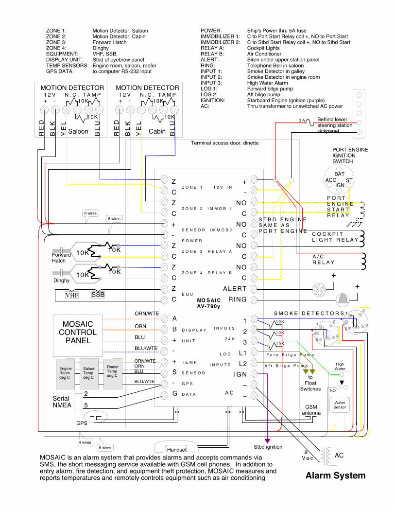
ZONE 1: Motion Detector, SaloonZONE 2: Motion Detector, CabinZONE 3: Forward HatchZONE 4: Dinghy EQUIPMENT: VHF, SSB,DISPLAY UNIT: Stbd of eyebrow panelTEMP SENSORS: Engine room, saloon, reeferGPS DATA: to computer RS-232 input
POWER: Ship's Power thru 5A fuseIMMOBILIZER 1: C to Port Start Relay coil +, NO to Port StartIMMOBILIZER 2: C to Stbd Start Relay coil +, NO to Stbd StartRELAY A: Cockpit LightsRELAY B: Air ConditionerALERT: Siren under upper station panelRING: Telephone Bell in saloonINPUT 1: Smoke Detector in galleyINPUT 2: Smoke Detector in engine roomINPUT 3: High Water AlarmLOG 1: Forward bilge pumpLOG 2: Aft bilge pumpIGNITION: Starboard Engine Ignition (purple)AC: Thru transformer to unswitched AC power
1 2 V N . C . T A M P+ -
RE
DB
LK
YE
L
BL
U
10K
MOTION DETECTOR
MOSAICCONTROL
PANEL
ORN/WTE
ORN
BLU
BLU/WTE
10K
1 0 K
10KForwardHatch
VHF SSB
ReeferTempdeg C
52Serial
NMEA
PORT ENGINEIGNITIONSWITCH
BATACC ST
IGN
P O R TE N G I N ES T A R T R E L A Y
C O C K P I TL I G H T R E L A Y
A / C R E L A Y
++
1 2
34
5
S M O K E D E T E C T O R S
AC
S T B D E N G I N ES A M E A SP O R T E N G I N E
9 V a c
A f t B i l g e P u m p
Alarm System
MOSAIC is an alarm system that provides alarms and accepts commands via SMS, the short messaging service available with GSM cell phones. In addition to entry alarm, fire detection, and equipment theft protection, MOSAIC measures and reports temperatures and remotely controls equipment such as air conditioning
1 2 V N . C . T A M P+ -
RE
DB
LK
YE
L
BL
U
10K
MOTION DETECTOR
10K
Saloon Cabin
Behind lower steering station kickpanel
10K 10KDinghy
F o r e B i l g e P u m pORN/WTEORNBLU
BLU/WTE
EngineRoomdeg C
SaloonTempdeg C
10K
1 2
34
5
Terminal access door, dinette
toFloat
Switches
4 wires6 wires
6 wires8 wires
GPS
GSMantenna
Handset Stbd ignition
3 A
ZCZC+-ZCZCZC
Z O N E 1
Z O N E 2
S E N S O R
P O W E R
Z O N E 3
Z O N E 4
E Q UMO SAICAV-790y
+-
NOC
NOC
NOC
NOC
ALERTRING
1 2 V I N
I M M O B 1
I M M O B 2
R E L A Y A
R E L A Y B
123
L1L2
IGN~~
I N P U T S
2 4 H
A C
L O G
I N P U T S
AB+-+S-G
D I S P L A Y
U N I T
T E M P
S E N S O R
G P S
D A T A
WaterSensor
NO
1 0 K
1 0 K
HighWater
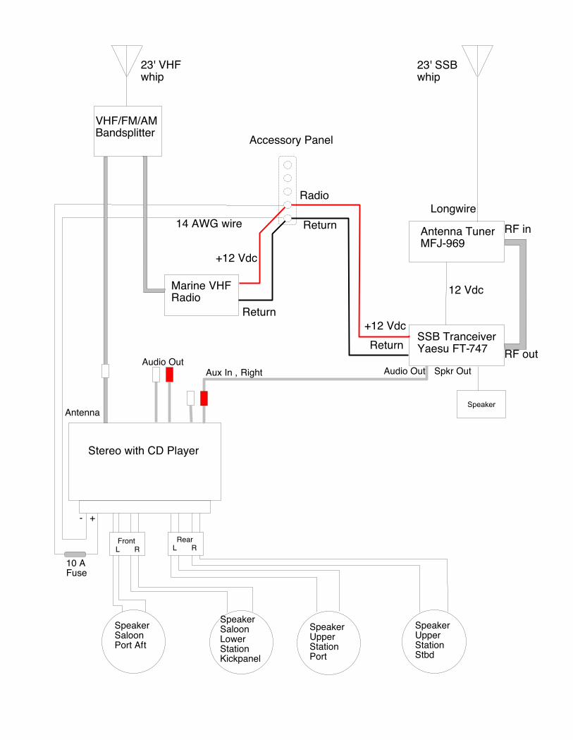
Stereo with CD Player
VHF/FM/AMBandsplitter
23' VHFwhip
23' SSBwhip
SpeakerSaloonPort Aft
SpeakerSaloonLower Station Kickpanel
SpeakerUpper StationPort
SpeakerUpper StationStbd
Marine VHFRadio
SSB TranceiverYaesu FT-747
Antenna TunerMFJ-969
Audio OutAux In , RightAudio Out
Accessory Panel
Radio
12 Vdc
RF out
RF inLongwire
+12 VdcReturn
+12 Vdc
Return
Antenna
+-
10 AFuse
Return14 AWG wire
FrontL R
RearL R
Speaker
Spkr Out

Clark headphones
Clark microphone
Clark PTT switch
1 2
1 3
WTE
RED
BLK GRN
2
RED
GRN
1 32
WTE
RED
RED
WTE