wiring accessories and spare parts - horner automation · acc106 screw-clamp i/o plug, 6 pin (10...
TRANSCRIPT

Wiring Accessories and Spare Parts
Third Edition 09 July 2002
MAN0347-04

.

MAN0347-04 09 JUL 2002 PAGE 3
PREFACE This supplement is provided for Horner APG’s Wiring Accessories and Spare Parts. Copyright (C) 2002 Horner APG, LLC., 640 North Sherman Drive Indianapolis, Indiana 46201. All rights reserved. No part of this publication may be reproduced, transmitted, transcribed, stored in a retrieval system, or translated into any language or computer language, in any form by any means, electronic, mechanical, magnetic, optical, chemical, manual or otherwise, without the prior agreement and written permission of Horner APG, LLC. All software described in this document or media is also copyrighted material subject to the terms and conditions of the Horner Software License Agreement. Information in this document is subject to change without notice and does not represent a commitment on the part of Horner APG, LLC. CsCAPE, CsCAN, and SmartStack is a registered trademark of Horner APG, LLC. DeviceNet is a registered trademark of Open DeviceNet Vendor Association, Inc. (OVDA) For user manual updates, contact Horner APG, Technical Support Division, at (317) 916-4274 or visit our website at www.heapg.com.

PAGE 4 09 JUL 2002 MAN0347-04
LIMITED WARRANTY AND LIMITATION OF LIABILITY Horner APG, LLC. ("HE -APG") warrants to the original purchaser that Wiring Accessories and Spare Parts manufactured by HE-APG are free from defects in material and workmanship under normal use and service. The obligation of HE-APG under this warranty shall be limited to the repair or exchange of any part or parts which may prove defective under normal use and service within two (2) years from the date of manufacture or eighteen (18) months from the date of installation by the original purchaser whichever occurs first, such defect to be disclosed to the satisfaction of HE after examination by HE-APG of the allegedly defective part or parts. THIS WARRANTY IS EXPRESSLY IN LIEU OF ALL OTHER WARRANTIES EXPRESSED OR IMPLIED INCLUDING THE WARRANTIES OF MERCHANTABILITY AND FITNESS FOR USE AND OF ALL OTHER OBLIGATIONS OR LIABILITIES AND HE-APG NEITHER ASSUMES, NOR AUTHORIZES ANY OTHER PERSON Wiring Accessories and Spare Parts TO ASSUME FOR HE-APG, ANY OTHER LIABILITY IN CONNECTION WITH THE SALE OF THESE. THIS WARRANTY SHALL NOT APPLY TO THESE Wiring Accessories and Spare Parts OR ANY PART THEREOF WHICH HAS BEEN SUBJECT TO ACCIDENT, NEGLIGENCE, ALTERATION, ABUSE, OR MISUSE. HE-APG MAKES NO WARRANTY WHATSOEVER IN RESPECT TO ACCESSORIES OR PARTS NOT SUPPLIED BY HE-APG. THE TERM "ORIGINAL PURCHASER", AS USED IN THIS WARRANTY, SHALL BE DEEMED TO MEAN THAT PERSON FOR WHOM THE Wiring Accessories and Spare Parts ARE ORIGINALLY INSTALLED. THIS WARRANTY SHALL APPLY ONLY WITHIN THE BOUNDARIES OF THE CONTINENTAL UNITED STATES. In no event, whether as a result of breach of contract, warranty, tort (including negligence) or otherwise, shall HE -APG or its suppliers be liable of any special, consequential, incidental or penal damages including, but not limited to, loss of profit or revenues, loss of use of the modules or any associated equipment, damage to associated equipment, cost of capital, cost of substitute modules, facilities, services or replacement power, down time costs, or claims of original purchaser's customers for such damages. To obtain warranty service, return the product to your distributor with a description of the problem, proof of purchase, post paid, insured and in a suitable package. ABOUT PROGRAMMING EXAMPLES Any example programs and program segments in this manual or provided on accompanying diskettes are included solely for illustrative purposes. Due to the many variables and requirements associated with any particular installation, Horner APG cannot assume responsibility or liability for actual use based on the examples and diagrams. It is the sole responsibility of the system designer utilizing Wiring Accessories and Spare Parts network to appropriately design the end system, to appropriately integrate the Wiring Accessories and Spare Parts network and to make safety provisions for the end equipment as is usual and customary in industrial applications as defined in any codes or standards which apply. Note: The programming examples shown in this manual are for illustrative purposes only.
Proper machine operation is the sole responsibility of the system integrator.

MAN0347-04 09 JUL 2002 PAGE 5
Revisions to this Manual 1. Revised Section 1.1 and 1.2 by adding the Color Touch OCS. 2. Moved the SmartStack Wiring Accessories section from Chapter 2 into its own chapter (Chapter
3). 3. Added new terminal options to SmartStack Wiring Accessories for DIQ935 and DIQ937 and
renumbered the chapter accordingly. Added example hookup and example wiring and have provided connector dimensions.
4. Moved Spare Parts from Chapter 3 to Chapter 5. 5. Expanded index to include individual part numbers.

PAGE 6 09 JUL 2002 MAN0347-04
MAN0347-04 09 JUL 2002 PAGE 7
TABLE OF CONTENTS PREFACE ..........................................................................................................................................3 LIMITED WARRANTY AND LIMITATION OF LIABILITY .......................................................................4 ABOUT PROGRAMMING EXAMPLES ................................................................................................4 TABLE OF CONTENTS ......................................................................................................................7 CHAPTER 1: INTRODUCTION...........................................................................................................9
1.1 Scope ...................................................................................................................................9 1.2 References ...........................................................................................................................9 1.3 Technical Support .................................................................................................................9
CHAPTER 2: WIRING ACCESSORIES.............................................................................................11 I/O CONNECTORS AND PLUGS ......................................................................................................11
2.1 Screw-Type Cage Clamps ...................................................................................................11 2.2 DIN-Rail Mount Terminal Block / Cables ...............................................................................12 2.3 I/O Modules Parts List..........................................................................................................13 2.4 RCS Mounting Bracket (HE800ACC210)...............................................................................16
CHAPTER 3: SMARTSTACK WIRING ACCESSORIES .....................................................................17 3.1. DIQ935 and DIQ937 Termination Options .............................................................................17 3.2 DIQ935 Termination Options ................................................................................................17 3.3 DIQ937 Termination Options ................................................................................................19
CHAPTER 4: SPARE PARTS ...........................................................................................................27 INDEX .............................................................................................................................................29

PAGE 8 09 JUL 2002 MAN0347-04

MAN0347-04 09 JUL 2002 PAGE 9 CH. 1
CHAPTER 1: INTRODUCTION 1.1 Scope This manual covers wiring accessories and spare parts that are available for use with Control Station products (e.g., OCS, RCS, Mini OCS, Graphic OCS, FOX, Color Touch OCS, SmartStack and MINI I/O Modules). 1.2 References
Table 1.1 –References / Manuals for Control Station Products
Control Station Operator Control Station, (OCS1xx-2xx) Graphic OCS (OCS250) Remote Control Station (RCS2xx) FOX104, FOX404, FOX100, SFX100 Color Touch OCS (OCS3xx) Mini OCS/RCS Hardware Manual OCSxxx / RCSxxx (Contains individual data sheets for various models.) SmartStack Supplement (Contains individual data sheets for various models.)
Cscape Programming Reference (OSW232) OCS DeviceNet Manual (OCS/RCS products in used in DeviceNet applications.)
1.3 Technical Support For assistance, contact Technical Support at the following locations: North America: (317) 916-4274 or visit our website at www.heapg.com. Europe: (+) 353-21-4321-266

PAGE 10 09 JUL 2002 MAN0347-04 CH. 1
NOTES
MAN0347-04 09 JUL 2002 PAGE 11 CH. 2
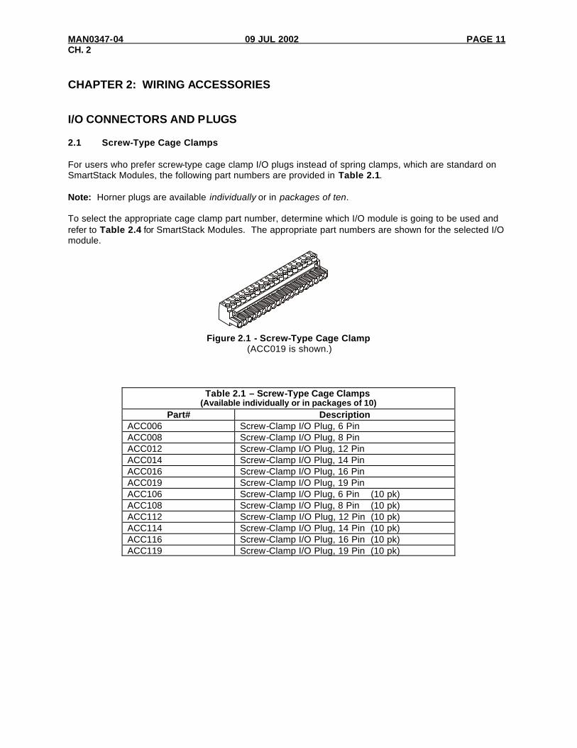
CHAPTER 2: WIRING ACCESSORIES I/O CONNECTORS AND PLUGS 2.1 Screw-Type Cage Clamps For users who prefer screw-type cage clamp I/O plugs instead of spring clamps, which are standard on SmartStack Modules, the following part numbers are provided in Table 2.1. Note: Horner plugs are available individually or in packages of ten. To select the appropriate cage clamp part number, determine which I/O module is going to be used and refer to Table 2.4 for SmartStack Modules. The appropriate part numbers are shown for the selected I/O module.
Figure 2.1 - Screw-Type Cage Clamp (ACC019 is shown.)
Table 2.1 – Screw-Type Cage Clamps (Available individually or in packages of 10)
Part# Description ACC006 Screw-Clamp I/O Plug, 6 Pin ACC008 Screw-Clamp I/O Plug, 8 Pin ACC012 Screw-Clamp I/O Plug, 12 Pin ACC014 Screw-Clamp I/O Plug, 14 Pin ACC016 Screw-Clamp I/O Plug, 16 Pin ACC019 Screw-Clamp I/O Plug, 19 Pin ACC106 Screw-Clamp I/O Plug, 6 Pin (10 pk) ACC108 Screw-Clamp I/O Plug, 8 Pin (10 pk) ACC112 Screw-Clamp I/O Plug, 12 Pin (10 pk) ACC114 Screw-Clamp I/O Plug, 14 Pin (10 pk) ACC116 Screw-Clamp I/O Plug, 16 Pin (10 pk) ACC119 Screw-Clamp I/O Plug, 19 Pin (10 pk)

PAGE 12 09 JUL 2002 MAN0347-04 CH. 2
2.2 DIN-Rail Mount Terminal Block / Cables For users who prefer to terminate I/O wiring on a pre-wired DIN Rail Mounted Terminal Strip instead of directly wiring to I/O modules, the following part numbers are provided in Table 2.2 and Table 2.3. To select the appropriate DIN Rail Mounted Terminal Block / cable part numbers, determine which I/O module is going to be used and the length of the cable required. Refer to Table 2.4 (for SmartStack Modules) or Table 2.5 (for Mini OCS). The appropriate part numbers are shown for the selected I/O module, and the cable required is indicated.
Figure 2.2 - Connectors for DIN-Rail Mount Terminal Block Termination
Table 2.2 – DIN-Rail Mount Terminal Block Part# Description
ACC512 DIN-Rail Mount Terminal Block, 12-pin ACC519 DIN-Rail Mount Terminal Block, 19-pin
Table 2.3 – Extension Cable Part# Description
CBL012 I/O Extension Cable (Analog), 12 Pin, .5M CBL022 I/O Extension Cable (Digital), 12 Pin, 0.5M CBL112 I/O Extension Cable (Analog), 12 Pin, 1.0M CBL122 I/O Extension Cable (Digital), 12 Pin, 1.0M CBL212 I/O Extension Cable (Analog), 12 Pin, 2.0M CBL222 I/O Extension Cable (Digital), 12 Pin, 2.0M CBL019 I/O Extension Cable , 19 Pin, .5M CBL119 I/O Extension Cable, 19 Pin, 1.0M CBL219 I/O Extension Cable, 19 Pin, 2.0M
CBL019 Shown
Plugs into OCS
Plugs into DIN-Rail Mount Terminal Block
DIN-Rail Mount Terminal Block (ACC512 Shown)

MAN0347-04 09 JUL 2002 PAGE 13 CH. 2
2.3 I/O Modules Parts List To select the appropriate part number(s), determine which I/O module is going to be used and refer to Table 2.4 (for SmartStack Modules) or Table 2.5 (for Mini OCS). The appropriate part numbers are shown for the selected I/O module. Note: Pre-wired terminal cables are available in three lengths. Tables 2.4 and 2.5 list the appropriate
cables for each SmartStack module and Mini OCS respectively. The Pre-wired Terminal Cable part numbers shown have an "x" in place of the digit that indicates length. When ordering the cable, the "x" is replaced by "0" for a 0.5m cable, “1” for a 1.0m cable, and “2” for a 2.0m cable.
Table 2.4 – Cross-Reference Parts List for SmartStack I/O Modules
Standard Density Digital I/O Modules SmartStack
Module Cage Clamp I/O Terminal
(single)
Cage Clamp I/O Terminal (10-pack)
DIN-rail mount Terminal Strip
Pre-wired Terminal Cable
DIM210 HE800ACC016 HE800ACC116 n/a n/a
DQM202 HE800ACC018 HE800ACC118 n/a n/a DIQ611 HE800ACC019 HE800ACC119 HE800ACC519 HE800CBLx19
DIQ612 HE800ACC019 HE800ACC119 HE800ACC519 HE800CBLx19
DIQ616 HE800ACC019 HE800ACC119 HE800ACC519 HE800CBLx19 DIQ622 HE800ACC019 HE800ACC119 HE800ACC519 HE800CBLx19
DIQ624 HE800ACC019 HE800ACC119 HE800ACC519 HE800CBLx19
HSC600 HE800ACC019 HE800ACC119 HE800ACC519 HE800CBLx19 HSC601 HE800ACC019 HE800ACC119 HE800ACC519 HE800CBLx19
High Density Digital I/O Modules SmartStack Cage Clamp Cage Clamp DIN-rail mount Pre-wired Terminal
Module I/O Terminal (single)
I/O Terminal (10-pack) Terminal Strip Cable
DIQ711 (trm A) HE800ACC019 HE800ACC119 HE800ACC519 HE800CBLx19 (trm B) HE800ACC019 HE800ACC119 HE800ACC519 HE800CBLx19
DIQ712 (trm A) HE800ACC019 HE800ACC119 HE800ACC519 HE800CBLx19 (trm B) HE800ACC012 HE800ACC112 HE800ACC512 HE800CBLx22
DIQ716 (trm A) HE800ACC019 HE800ACC119 HE800ACC519 HE800CBLx19 (trm B) HE800ACC019 HE800ACC119 HE800ACC519 HE800CBLx19
DIQ722 (trm A) HE800ACC019 HE800ACC119 HE800ACC519 HE800CBLx19 (trm B) HE800ACC012 HE800ACC112 HE800ACC512 HE800CBLx22
Mixed Digital & Analog Modules
SmartStack Cage Clamp Cage Clamp DIN-rail mount Pre-wired Terminal Module I/O Terminal
(single) I/O Terminal (10-pack) Terminal Strip Cable
MIX901 (trm A) HE800ACC019 HE800ACC119 HE800ACC519 HE800CBLx19 (trm B) HE800ACC008 HE800ACC108 n/a n/a
MIX902 (trm A) HE800ACC019 HE800ACC119 HE800ACC519 HE800CBLx19 (trm B) HE800ACC008 HE800ACC108 n/a n/a
MIX905 (trm A) HE800ACC019 HE800ACC119 HE800ACC519 HE800CBLx19 (trm B) HE800ACC008 HE800ACC108 n/a n/a

PAGE 14 09 JUL 2002 MAN0347-04 CH. 2
Table 2.4 Continued: Cross-Reference Parts List for SmartStack I/O Modules
Analog I/O Modules
SmartStack Cage Clamp Cage Clamp DIN-rail mount Pre-wired Terminal
Module I/O Terminal (single) I/O Terminal (10-pack) Terminal Strip Cable ADC010 HE800ACC006 HE800ACC106 n/a n/a ADC020 HE800ACC006 HE800ACC106 n/a n/a ADC110 HE800ACC012 HE800ACC112 HE800ACC512 HE800CBLx12 ADC120 HE800ACC012 HE800ACC112 HE800ACC512 HE800CBLx12 ADC920 HE800ACC019 HE800ACC119 HE800ACC519 HE800CBLx19 DAC001 HE800ACC006 HE800ACC106 n/a n/a DAC002 HE800ACC006 HE800ACC106 n/a n/a DAC101 HE800ACC012 HE800ACC112 HE800ACC512 HE800CBLx12 DAC102 HE800ACC012 HE800ACC112 HE800ACC512 HE800CBLx12 MIX011 HE800ACC006 HE800ACC106 n/a n/a MIX022 HE800ACC006 HE800ACC106 n/a n/a MIX111 HE800ACC012 HE800ACC112 HE800ACC512 HE800CBLx12 MIX122 HE800ACC012 HE800ACC112 HE800ACC512 HE800CBLx12 RTD000 HE800ACC008 HE800ACC108 n/a n/a RTD100 HE800ACC016 HE800ACC116 n/a n/a THM000 HE800ACC006 HE800ACC106 n/a n/a THM100 HE800ACC014 HE800ACC114 n/a n/a
Specialty Modules
SmartStack Cage Clamp Cage Clamp DIN-rail mount Pre-wired Terminal Module I/O Terminal (single) I/O Terminal (10-pack) Terminal Strip Cable
HSC600 HE800ACC019 HE800ACC119 HE800ACC519 HE800CBLx19 HSC601 HE800ACC019 HE800ACC119 HE800ACC519 HE800CBLx19 STP100 HE800ACC019 HE800ACC119 HE800ACC519 HE800CBLx19

MAN0347-04 09 JUL 2002 PAGE 15 CH. 2
Table 2.5 – Cross-Reference Parts List for Mini OCS Modules
Mini OCS Models DIN-rail mount Terminal Strip Pre-wired Terminal Cable
OCS031 HE800ACC519 HE800CBLx19 OCS032 HE800ACC519 HE800CBLx19
OCS033 HE800ACC519 HE800CBLx19 OCS034 HE800ACC519 HE800CBLx19
OCS035 HE800ACC519 HE800CBLx19 OCS036 HE800ACC519 HE800CBLx19 OCS037 HE800ACC519 HE800CBLx19
OCS041 (trm A) HE800ACC519 HE800CBLx19 (trm B) HE800ACC519 HE800CBLx19
OCS042 (trm A) HE800ACC519 HE800CBLx19 (trm B) HE800ACC519 HE800CBLx19
OCS45 (trm A) HE800ACC519 HE800CBLx19 (trm B) HE800ACC512 HE800CBLx22
OCS47 (trm A) HE800ACC519 HE800CBLx19 (trm B) HE800ACC512 HE800CBLx22
OCS052 (trm A) HE800ACC519 HE800CBLx19 (trm B) n/a n/a
OCS053 (trm A) HE800ACC519 HE800CBLx19 (trm B) n/a n/a
OCS056 (trm A) HE800ACC519 HE800CBLx19 (trm B) n/a n/a
OCS061 HE800ACC519 HE800CBLx19
OCS062 HE800ACC519 HE800CBLx19 OCS063 HE800ACC519 HE800CBLx19
OCS064 HE800ACC519 HE800CBLx19 OCS065 HE800ACC519 HE800CBLx19
OCS066 HE800ACC519 HE800CBLx19 OCS067 HE800ACC519 HE800CBLx19
OCS071 (trm A) HE800ACC519 HE800CBLx19 (trm B) HE800ACC519 HE800CBLx19
OCS072 (trm A) HE800ACC519 HE800CBLx19 (trm B) HE800ACC519 HE800CBLx19
OCS075 (trm A) HE800ACC519 HE800CBLx19 (trm B) HE800ACC512 HE800CBLx22
OCS077 (trm A) HE800ACC519 HE800CBLx19 (trm B) HE800ACC512 HE800CBLx22
OCS082 (trm A) HE800ACC519 HE800CBLx19 (trm B) n/a n/a
OCS083 (trm A) HE800ACC519 HE800CBLx19 (trm B) n/a n/a
OCS086 (trm A) HE800ACC519 HE800CBLx19
(trm B) n/a n/a

PAGE 16 09 JUL 2002 MAN0347-04 CH. 2
2.4 RCS Mounting Bracket (HE800ACC210) The optional mounting bracket is used with SmartStack modules that have connectors located on two sides. (Note that many SmartStack modules only have connectors on one side.) Figure 2.3 depicts how to mount the bracket to an RCS.
Figure 2.3 – RCS and Optional Mounting Bracket NOTE: Use #8-32 mounting hardware consisting of four 8-32 pan head screws with external tooth Lock washers.
Figure 2.4 – Drill Pattern for the RCS Optional Mounting Bracket (HE800ACC210)
6.312 (160.32 mm)
1.250 (31.75 mm)
RCS
HE800ACC210

MAN0347-04 09 JUL 2002 PAGE 17 CH. 3
CHAPTER 3: SMARTSTACK WIRING ACCESSORIES 3.1. DIQ935 and DIQ937 Termination Options The following termination options are available for the DIQ935 and DIQ937. The DIQ935 is a 32 in / 40 out DC I/O module featuring two 44-pin high density D-Subs for wiring termination. The DIQ937 features four 26-pin IDC ribbon connectors for wiring termination. DIQ935 Option A. Customer construction of a custom wiring harness assembly. Option B. Pre-fabricated round cable, terminated to DIN-rail mount terminal strips. DIQ937 Option C. Pre-fabricated ribbon cables, terminated to DIN-rail mount terminal strips. Option D. Pre-fabricated ribbon cables, terminated to DIN-rail mount signal conditioners. 3.2 DIQ935 Termination Options
Note: Prior to the DIQ937, the DST935 was used for termination for the DIQ935. Option A: Customer Constructed Wiring Harness For construction of a custom wiring harness, the D-sub connectors and pins can be obtained from a variety of sources including Digi-Key Corporation (1-800-344-4539). The part numbers are:
Description Manufacturer Manufacturer Part # Digi-Key Part # D-Sub Connector 44 (Male)
AMP 748366-1 A2078-ND
D-Sub Pin for D-Sub Connector (22-28 AWG), 30µµ Gold
AMP 748333-4 A2088-ND
Option B: Pre-Fabricated Round Cable, Terminated To DIN-Rail Mount Terminal Strips. For this option, the customer terminates his I/O wiring to passive, DIN-rail mount terminal strips. These strips are connected to the DIQ935 via a round cable 0.5m, 1.0m, or 2.0m in length. To increase the panel layout flexibility of this option, the 44-pins of termination are divided into two DIN-rail mounted terminal strips (24 pin and 20 pin). The required cable is constructed in a "Y" configuration, with a 44-pin D-sub on one end, and a 24-pin connector and 20-pin connector on the other end. The part numbers for the cables and terminal strip are shown in the following table. Note that it takes two cables, and two sets of ACC544 terminal strips to wire all 32 inputs and 40 outputs of a DIQ935 module. This wiring option is passive. The terminal strips provide no filtering or signal conditioning to improve noise immunity.

PAGE 18 09 JUL 2002 MAN0347-04 CH. 3
Figure 3.1 - Round Cable and ACC544
Close-up of ACC544 Figure 3.2 - End View Figure 3.3 - Top View
Table 3.1 - Dimensions of Din-Rail Mount Terminal Block Part Number Description * Dimension “A”:
ACC512 12-PIN 2.40” (60.96mm) ACC519 19-PIN 3.80” (96.52mm) ACC544 44-PIN (Consists of 2 connectors)
44-PIN (Total)
20-PIN 24-PIN
9.00” (228.6mm) 4.08” (103.6mm) 4.90” (124.5mm)
001ACC001
1.42[36.1mm]
1.600[40.6mm]
35 mmDINRAIL
4.90[124.5mm]
001ACC004
20 PIN CONN.
24 PIN CONN.
4.08[103.6mm]
* Dimension “A”

MAN0347-04 09 JUL 2002 PAGE 19 CH. 3
Table 3.2 - Pin-out for Connection of HE800CBLx44 between DIQ935 SmartStack Module and HE800ACC544
DIQ935 I/O Signal Name
ACC544 DIN-Rail Terminal Strip
Number
DIQ935 I/O Signal Name
ACC544 DIN-Rail Terminal Strip
Number Common 1 Input/Output 22 23
Input/Output 1 2 Common 24 Input/Output 2 3 Common 25 Input/Output 3 4 Input/Output 23 26 Input/Output 4 5 Input/Output 24 27 Input/Output 5 6 Input/Output 25 28 Input/Output 6 7 Input/Output 26 29 Input/Output 7 8 Input/Output 27 30 Input/Output 8 9 Input/Output 28 31 Input/Output 9 10 Input/Output 29 32
Input/Output 10 11 Input/Output 30 33 Input/Output 11 12 Input/Output 31 34 Input/Output 12 13 Input/Output 32 35 Input/Output 13 14 Input NC/Output 33 36 Input/Output 14 15 Input NC/Output 34 37 Input/Output 15 16 Input NC/Output 35 38 Input/Output 16 17 Input NC/Output 36 39 Input/Output 17 18 Input NC/Output 37 40 Input/Output 18 19 Input NC/Output 38 41 Input/Output 19 20 Input NC/Output 39 42 Input/Output 20 21 Input NC/Output 40 43 Input/Output 21 22 Common 44
Note: To connect to all 32 inputs and 40 outputs of the DIQ935 module, a total of two CBLx44s and two ACC544s are required.
3.3 DIQ937 Termination Options Option C: Pre-Fabricated Ribbon Cable, Terminated To DIN-Rail Mount Terminal Strips. This option is very similar to Option B, but utilizes ribbon cables instead of round cables. The DIQ937 High-Density I/O utilizes four 26-pin ribbon connectors instead of two High-Density D-sub connectors. Two of the ribbon connectors are used for inputs (16 inputs each), and two of the ribbon connectors are used for outputs (16 outputs each). Because ribbon cables are used, a different DIN-rail mount terminal strip is used. Note that it takes four ribbon cables and four DIN-rail mount terminal strips to wire 32 inputs and 40 outputs of a DIQ937 module. This wiring option is passive. The terminal strips provide no filtering or signal conditioning to improve noise immunity. Note: The DIQ937 plus the necessary cables and terminal strips to wire 32 inputs and 40 outputs
are available as a single kit. The DIQ937-20 part number was created for this purpose.

PAGE 20 09 JUL 2002 MAN0347-04 CH. 3
Figure 3.4 - DIQ937-20 110 Kit
The DIQ937-20 Kit includes a DIQ937 module, four DIN-rail mount terminal strips and four 1m round ribbon cables.
DIQ937
TERMINALTRM500
TERMINALTRM500
TERMINALTRM500
001ACC006
J1
J2
J4
J3Pin 1
Pin 1
TERMINALTRM500

MAN0347-04 09 JUL 2002 PAGE 21 CH. 3
Table 3.3 – TRM500 AND DIQ937 I/O PINS (Refer To Figure 3.4 For Diq937 Jack Locations )
TRM500 Pin DIQ937 J1 DIQ937 J2 DIQ937 J3 DIQ937 J4 1 Input 1 Input 17 Output 1 Output 17 2 Input 2 Input 18 Output 2 Output 18 3 Input 3 Input 19 Output 3 Output 19 4 Input 4 Input 20 Output 4 Output 20 5 Input 5 Input 21 Output 5 Output 21 6 Input 6 Input 22 Output 6 Output 22 7 Input 7 Input 23 Output 7 Output 23 8 Input 8 Input 24 Output 8 Output 24
9 & 10 Common (GND) Common (GND) Common (GND) Common (GND) 11 Output 33 Output 37 12 Output 34 Output 38 13 Output 35 Output 39 14
NC NC
Output 36 Output 40 15 & 16 Common (GND) Common (GND) Common (GND) Common (GND)
17 Input 16 Input 32 Output 16 Output 32 18 Input 15 Input 31 Output 15 Output 31 19 Input 14 Input 30 Output 14 Output 30 20 Input 13 Input 29 Output 13 Output 29 21 Input 12 Input 28 Output 12 Output 28 22 Input 11 Input 27 Output 11 Output 27 23 Input 10 Input 26 Output 10 Output 26 24 Input 9 Input 25 Output 9 Output 25
25 & 26 NC NC NC NC
Figure 3.5 - TRM500
12
34
56
7 89
1011
1213
1415
16
212325
1719 18
20222426
25 26
1 2
3.00[76.2mm]
2.00[50.8mm]
001ACC002-R1

PAGE 22 09 JUL 2002 MAN0347-04 CH. 3
Option D: Pre-fabricated ribbon cable, terminated to DIN-rail mount signal conditioners and
output devices. This option is very similar to Option C, but it utilizes active signal conditioners instead of passive terminal strips. Once again, the use of a DIQ937 is required. Two of the ribbon connectors are used for inputs (16 inputs each). For each set of 16 inputs, a DIN-rail mount input conditioner (INP935) is used. This input conditioner provides protective circuitry for the DIQ937 inputs. Two of the ribbon connectors on the DIQ937 are used for outputs (16 outputs each). For each set of 16 outputs, a DIN-rail mount relay output device (RLY160) is used. This output device provides 16 high current relays, each with isolated normally open contacts, which can accept an AC or DC load. Note that with this option, outputs 33-40 are not accessible. The part numbers for the cables, input conditioners, and relay output conditioner is shown in the table below. Note that it takes four ribbon cables, two input conditioners, and two relay output devices to wire 32 inputs and 32 outputs of a DIQ937 module.
Figure 3.6 – Example Hookup of the DIQ935, INP935, and RLY160 (Kit: DQT935) 0 0 1 A C C 0 0 7
J1
J2
J4
J3Pin 1
Pin 1
24VDC
P2P1
P3
P4
1
1
4B
2B
5B
1A
1B
2A
3A
3B
4A
8B
8A
7B
7A
6B
6A
5A
13B
15B
12B
16B
16A
15A
14B
14A
9A9B10A
10B
11A
11B
12A
13A
24VDC
P2P1
P3
P4
1
1
4B
2B
5B
1A
1B
2A
3A
3B
4A
8B
8A
7B
7A
6B
6A
5A
13B
15B
12B
16B
16A
15A
14B
14A
9A9B10A
10B
11A
11B
12A
13A
DIQ937
RLY160
INP935
INP935
RLY160
Terminal A Inputs 1-16
Terminal C Outputs 1-16
Terminal B Inputs 17-32
Terminal D Outputs 17-32
Note: The devices shown in this figure can be ordered as a kit (DQT935).

MAN0347-04 09 JUL 2002 PAGE 23 CH. 3
Pin-outs and Wiring for Example Hookup in Figure 3.6
Pin Description Pin Description 1 Input 1 13 Input 9 2 Input 2 14 Input 10 3 Common
(GND) 15 Common
(GND) 4 Input 3 16 Input 11 5 Input 4 17 Input 12 6 Common
(GND) 18 Common
(GND) 7 Input 5 19 Input 13 8 Input 6 20 Input 14 9 Common
(GND) 21 Common
(GND) 10 Input 7 22 Input 15 11 Input 8 23 Input 16 12 Common
(GND) 24 Common
(GND)
Pin Description Pin Description 1 Input 17 13 Input 25 2 Input 18 14 Input 26 3 Common
(GND) 15 Common
(GND) 4 Input 19 16 Input 27 5 Input 20 17 Input 28 6 Common
(GND) 18 Common
(GND) 7 Input 21 19 Input 29 8 Input 22 20 Input 30 9 Common
(GND) 21 Common
(GND) 10 Input 23 22 Input 31 11 Input 24 23 Input 32 12 Common
(GND) 24 Common
(GND)
J2
Pin 13 14 15 16 17 18 19 20 21 22 23 24
1 2 3 4 5 6 7 8 9 10 11 12
INPUT 17 18 C 19 20 C 21 22 C 23 24 C
Pin
INPUT 25 26 C 27 28 C 29 30 C 31 32 C
Terminal B Inputs 17-32 (INP935)
J2
Pin 13 14 15 16 17 18 19 20 21 22 23 24
1 2 3 4 5 6 7 8 9 10 11 12
INPUT 1 2 C 3 4 C 5 6 C 7 8 C
Pin
INPUT 9 10 C 11 12 C 13 14 C 15 16 C
Terminal A Inputs 1-16 (INP935)

PAGE 24 09 JUL 2002 MAN0347-04 CH. 3
Continued: Pin-outs and Wiring for Example Hookup in Figure 3.6
1A 1B 2A 2B 3A 3B 4A 4B 5A 5B 6A 6B 7A 7B 8A 8B
9A 9B 10A 10B 11A 11B 12A 12B 13A 13B 14A 14B 15A 15B 16A 16B
Output 17A 17B 18A 18B 19A 19B 20A 20B 21A 21B 22A 22B 23A 23B 24A 24B
Output 25A 25B 26A 26B 27A 27B 28A 28B 29A 29B 30A 30B 31A 31B 32A 32B
Terminal D Outputs 17-32
(RLY160)
Pins
Pins
1A 1B 2A 2B 3A 3B 4A 4B 5A 5B 6A 6B 7A 7B 8A 8B
9A 9B 10A 10B 11A 11B 12A 12B 13A 13B 14A 14B 15A 15B 16A 16B
Output 1A 1B 2A 2B 3A 3B 4A 4B 5A 5B 6A 6B 7A 7B 8A 8B
Output 9A 9B 10A 10B 11A 11B 12A 12B 13A 13B 14A 14B 15A 15B 16A 16B
Terminal C Outputs 1-16
(RLY160)
Pins
Pins

MAN0347-04 09 JUL 2002 PAGE 25 CH. 3
Figure 3.7 – RLY160
Figure 3.8 – RLY160 Dimensions
6.22"
6.62"
3.88
"
4.38
"
001ACC008
P1 P2
P3
1
1
1A 1B 2A 2B 3A 3B 4A 4B 5A 5B 6A 6B 7A 7B 8A 8B9A9B10
A10
B11
A11
B12
A12
B13
A13
B14
A14
B15
A15
B16
A16
B
P4
24VDC
F1
K1
F16
F16

PAGE 26 09 JUL 2002 MAN0347-04 CH. 3
Figure 3.9 - INP935 Connector
Figure 3.10 - INP935 Connector Dimensions
7.27[184.7mm]
2.50[63.5mm]
3.00[76.2mm]
6.87[174.5mm]
3.26[82.8mm]
001DIQ019
PIN 1 J1 J2 Ground terminal for optional panel ground.
13 14 15 16 17 18 19 20 21 22 23 24
1 2 3 4 5 6 7 8 9 10 11 12

MAN0347-04 09 JUL 2002 PAGE 27 CH. 4
CHAPTER 4: SPARE PARTS
Table 4.1 – Spare Parts Customer Part
Number Description
Spare I/O Plugs - SmartStack HE800TRM006 Spring-clamp style I/O plug, 6-terminal. (Qty 1). Spare or replacement for a standard
SmartStack plug. HE800TRM008 Spring-clamp style I/O plug, 8-terminal, spare. (Qty 1) HE800TRM012 Spring-clamp style I/O plug, 12-terminal, spare. (Qty 1)
HE800TRM014 Spring-clamp style I/O plug, 14-terminal, spare. (Qty 1)
HE800TRM016 Spring-clamp style I/O plug, 16-terminal, spare. (Qty 1)
HE800TRM019 Spring-clamp style I/O plug, 19-terminal, spare. (Qty 1)
Spare I/O Plugs - MiniOCS HE800TRM308 Cage-clamp (screw) style I/O plug, 8-terminal. (Qty 1). Spare or replacement for a
standard miniOCS plug.
HE800TRM312 Cage-clamp (screw) style I/O plug, 12-terminal. (Qty 1). Spare or replacement for a standard miniOCS plug.
HE800TRM319 Cage-clamp (screw) style I/O plug, 19-terminal. (Qty 1). Spare or replacement for a standard miniOCS plug.
Spare Plugs - OCS/RCS/MiniOCS
HE800TRM005 Cage-clamp (screw) style Network plug, 5-terminal, spare for OCS/RCS/miniOCS. (Qty 1)
HE800TRM002 Cage-clamp (screw) style Power plug, 2-terminal, spare for OCS100/200/250. (Qty 1)
HE800TRM003 Cage-clamp (screw) style Power/Ground plug, 3-terminal, spare for RCS/miniOCS. (Qty 1)
HE800TRM006 Cage-clamp (screw) style RS-485 / RS-232 plus, 6-terminial, spare for OCS250 (Qty. 1)
Spare Battery - OCS/RCS/MiniOCS
HE500BAT005 Replacement Battery for OCS/RCS.

PAGE 28 09 JUL 2002 MAN0347-04 CH. 4
NOTES

MAN0347-04 09 JUL 2002 PAGE 29
INDEX 748333-4......................................................17 748366-1......................................................17 A2078-ND ....................................................17 A2088-ND ....................................................17 ACC006 .......................................................11 ACC008 .......................................................11 ACC012 .......................................................11 ACC014 .......................................................11 ACC016 .......................................................11 ACC019 .......................................................11 ACC106 .......................................................11 ACC108 .......................................................11 ACC112 .......................................................11 ACC114 .......................................................11 ACC116 .......................................................11 ACC119 .......................................................11 ACC512 ................................................. 12, 18 ACC519 ................................................. 12, 18 ACC544 ............................................17, 18, 19 ADC010 ........................................................14 ADC020 ........................................................14 ADC110 ........................................................14 ADC920 ........................................................14 CBL012........................................................12 CBL019........................................................12 CBL022........................................................12 CBL112........................................................12 CBL119........................................................12 CBL122........................................................12 CBL212........................................................12 CBL219........................................................12 CBL222........................................................12 Cross-Reference Parts List for SmartStack.....13 Cross-Reference Parts List, Mini OCS ...........15 Customer Constructed Wiring Harness...........17 DAC001 ........................................................14 DAC002 ........................................................14 DAC101 ........................................................14 DAC102 ........................................................14 DIM210 .........................................................13 Dimensions of Din-Rail Mount Terminal Block.18 DIN-Rail Mount Terminal Block / Cables .........12 DIQ611 .........................................................13 DIQ612 .........................................................13 DIQ616 .........................................................13 DIQ622 .........................................................13 DIQ624 .........................................................13 DIQ711 .........................................................13 DIQ712 ................................................... 13, 15 DIQ716 .........................................................13 DIQ722 .........................................................13 DIQ935 .................................................. 17, 19
DIQ937 .............................................17, 19, 22 DIQ937 Pinout ...............................................21 DIQ937-20 ...................................................19 DIQ937-20 110 Kit ........................................20 DQM202........................................................13 DQT935 .......................................................22 DQT935 Kit ..................................................22 Example Hook-ups .......................................22 Extension Cable ...........................................12 HE500BAT005................................................27 HE690RLY160 .............................................22 HE800ACC006 ...............................................14 HE800ACC008 ......................................... 13, 14 HE800ACC012 ......................................... 13, 14 HE800ACC014 ...............................................14 HE800ACC016 ......................................... 13, 14 HE800ACC018 ...............................................13 HE800ACC019 ......................................... 13, 14 HE800ACC106 ...............................................14 HE800ACC108 ......................................... 13, 14 HE800ACC112 ......................................... 13, 14 HE800ACC114 ...............................................14 HE800ACC116 ......................................... 13, 14 HE800ACC118 ...............................................13 HE800ACC119 ......................................... 13, 14 HE800ACC210 .............................................16 HE800ACC512 ....................................13, 14, 15 HE800ACC519 ....................................13, 14, 15 HE800CBLx12................................................14 HE800CBLx19.....................................13, 14, 15 HE800CBLx22.......................................... 13, 15 HE800CBLx44..............................................19 HE800DIQ935..............................................17 HE800DIQ937..............................................17 HE800INP935 ..............................................22 HE800TRM002...............................................27 HE800TRM003...............................................27 HE800TRM005...............................................27 HE800TRM006...............................................27 HE800TRM008...............................................27 HE800TRM012...............................................27 HE800TRM014...............................................27 HE800TRM016...............................................27 HE800TRM019...............................................27 HE800TRM308...............................................27 HE800TRM312...............................................27 HE800TRM319...............................................27 HSC600 .................................................. 13, 14 HSC601 .................................................. 13, 14 INP935
Dimensions ...............................................26 INP935 Connector ........................................26

PAGE 30 09 JUL 2002 MAN0347-04
MIX011 .........................................................14 MIX022 .........................................................14 MIX111 .........................................................14 MIX122 .........................................................14 MIX901 .........................................................13 MIX902 .........................................................13 MIX905 .........................................................13 OCS031 ........................................................15 OCS032 ........................................................15 OCS034 ........................................................15 OCS035 ........................................................15 OCS036 ........................................................15 OCS037 ........................................................15 OCS041 ........................................................15 Optional Mounting Bracket, RCS ...................16 Pre-Fabricated Ribbon Cable, Terminated To
DIN-Rail Mount Terminal Strips ..................19 Pre-Fabricated Round Cable, Terminated To
DIN-Rail Mount Terminal Strips ..................17 RCS Optional Mounting Bracket ....................16
Drill Pattern...............................................16 References.....................................................9 RLY160........................................................25
Dimensions ...............................................25 Round Cable ................................................18 RTD000 ........................................................14 RTD100 ........................................................14 Scope ............................................................9 Screw-Type Cage Clamps .............................11 Spare Battery
OCS/RCS/Mini OCS ..................................27 Spare I/O Plugs
Mini OCS ..................................................27 SmartStack ...............................................27
Spare Parts ..................................................27 Spare Plugs
OCS/RCS/Mini OCS ..................................27 STP100.........................................................14 Technical Support ...........................................9 Termination Options ................................ 17, 19 THM000 ........................................................14 THM100 ........................................................14 TRM500
Dimensions ...............................................21 Pinout .......................................................21