wiresensor, wds
TRANSCRIPT

WDS-70-F50
Instruction Manual
wireSENSOR, WDS

Declaration of incorporation
Declaration of incorporation according to the EC Machinery Directive 2006/42/EC, Annex II B
Manufacturer and authorized representative for the compilation of the relevant technical documents
MICRO-EPSILON MESSTECHNIK GmbH & Co. KG
Königbacher Straße 15 94496 Ortenburg / Germany
hereby declares that the machine designated below, as a result of its manner of design, construction as well as version that has been placed on the market - to the extent possible in the scope of delivery - corresponds to the relevant, fundamental health and safety requirements of the EC Machinery Directive, including the valid changes at the time of declaration.
Model: wiresensor
Type designation: WDS-xxx, WPS-xxx
The following fundamental health and safety requirements in accordance with Annex I of the above-named directive are applied and maintained:
- No. 1.1.2. Principles of safety integration - No. 1.7.3. Marking of machinery - No. 1.7.4. Instructions

Furthermore, the compliance with the following EC Directives and standards is explained, including the valid changes at the time of this declaration:
- EN ISO 13857:2008 Safety of machinery - Safety distances to prevent hazard zones being reached by upper and lower limbs - EN 60204-1:2006 Safety of machinery - Electrical equipment of machines
Part 1: General requirements - DIN EN 61326-1: 2006-10 - DIN EN 61326-2-3: 2007-05
Moreover, we declare that the relevant technical documentation for this partly completed machinery has been created in accordance with part B of Annex VII, and that we shall be obligated to deliver these upon the request of the market surveillance authorities.
The described partly completed machinery is intended for installation in a production line.
The commissioning of this partly completed machinery shall be prohibited until the partly completed machinery has been installed in a machine that complies with the provision of the EC Machinery Directive and for which an EC Declaration of Conformity in accor-dance with Annex II A is available.
Ortenburg, May 5th 2015 Dr. Thomas Wisspeintner Managing Director
Tel. +49 (0) 8542 / 168-0 e-mail [email protected] Certified acc. to
Fax +49 (0) 8542 / 168-90 www.micro-epsilon.com DIN EN ISO 9001: 2008

wireSENSOR, WDS
Contents
1. Safety .......................................................................................................................................... 51.1 Symbols Used .................................................................................................................................................... 51.2 Warnings ............................................................................................................................................................ 51.3 Notes on CE Identification ................................................................................................................................. 61.4 Proper Use ......................................................................................................................................................... 71.5 Proper Environment ........................................................................................................................................... 71.6 Foreseeable Misuse ........................................................................................................................................... 7
2. Functional Principle, Technical Data ......................................................................................... 82.1 Functional Principle............................................................................................................................................ 82.2 Type Designation ............................................................................................................................................... 92.3 Technical Data ................................................................................................................................................. 10
3. Delivery ..................................................................................................................................... 123.1 Unpacking ........................................................................................................................................................ 123.2 Storage ............................................................................................................................................................. 12
4. Installation and Assembly ........................................................................................................ 134.1 Precautionary Measures .................................................................................................................................. 134.2 Sensor Mounting .............................................................................................................................................. 134.3 Wire Guide and Fastening ............................................................................................................................... 154.4 Power Supply and Display/Output Device ...................................................................................................... 16
5. Commissioning ........................................................................................................................ 17
6. Operation .................................................................................................................................. 18
7. Operation and Maintenance .................................................................................................... 18
8. Warranty .................................................................................................................................... 19
9. Decommissioning, Disposal .................................................................................................... 19
Appendix ................................................................................................................................... 20

wireSENSOR, WDS
Page 6
Safety
wireSENSOR, WDS
1. Safety
The handling of the sensor assumes knowledge of the instruction manual.
1.1 Symbols UsedThe following symbols are used in this instruction manual:
Indicates a hazardous situation which, if not avoided, may result in minor or moder-ate injury.
Indicates a situation which, if not avoided, may lead to property damage.
Indicates an user action.
i Indicates an user tip.
1.2 WarningsDo not open the sensor housing.
> Danger of injury from pre-tensioned spring motor
Do not let the measuring wire rewind without control (snap back). > Danger of injury from whiplash effect of the wire with assembly bolts/clips
> Destruction of wire and/or of sensor
Do not pull or loop the measuring wire around unprotected parts of the body. > Danger of injury
Connect the power supply in accordance with the safety regulations for electrical equipment. > Danger of injury
> Damage to or destruction of the sensor safety
Page 7
Safety
wireSENSOR, WDS
Do not pull the measuring wire over measuring range. > Destruction of the measuring wire and/or the sensor
Don´t let the power supply exceed the specified limits. > Damage to or destruction of the sensor
Avoid banging and knocking the sensor > Damage to or destruction of the sensor
1.3 Notes on CE IdentificationThe following applies to series WDS draw wire sensors: Directive 2006/42/EC
The following applies to series WDS draw wire sensors with voltage, current or encoder output: - EU directive 2004/108/EC - EU directive 2011/65/EC, “RoHS“ category 9
Products which carry the CE mark satisfy the requirements of the quoted EU directives and the European standards (EN) listed therein. The EC declaration of conformity is kept available to EU regulation, article 10 by the authorities responsible at
MICRO-EPSILON MESSTECHNIKGmbH & Co. KGKönigbacher Str. 1594496 Ortenburg / Germany
Draw wire sensors with potentiometer output are not automatically operable devices (components). An EC declaration of conformity or CE identification is therefore not issued by EMC law.
Draw wire sensors with encoder output carry the CE mark.
Sources: EMC law, Guidelines on the application of council directive 2004/108/EC, directive 2006/42/EC.

Page 8
Safety
wireSENSOR, WDS
1.4 Proper Use - Draw wire sensors are used for
� distance or displacement measuring � position determination of components or moving machine parts.
- The sensors may only be operated within the limits specified in the technical data, see Chap. 2. - Draw wire sensors should only be used in such a way that in case of malfunction or failure personnel or
machinery are not endangered. - Additional precautions for safety and damage prevention must be taken for safety-related applications.
1.5 Proper Environment - Protection class for sensor IP00 - Operating temperature: -40 °C to +100 °C (-40 to +212 °F) - Storage temperature: -40 °C to +100 °C (-40 to +212 °F) - Humidity: 5 - 95 % (non-condensing) - Ambient pressure: atmospheric pressure
1.6 Foreseeable MisuseDo not further extract the measuring wire but only to the specified measuring range. This may lead to dam-age of the measuring wire and also to uncontrollable snapping of the measuring wire. Danger of injury.
Make sure the sensor is not held by another person when the measuring wire is extracted. Danger of snap-ping and injury.
Page 9
Functional Principle, Technical Data
wireSENSOR, WDS
2. Functional Principle, Technical Data
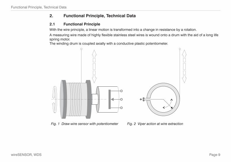
2.1 Functional PrincipleWith the wire principle, a linear motion is transformed into a change in resistance by a rotation.
A measuring wire made of highly flexible stainless steel wires is wound onto a drum with the aid of a long life spring motor.The winding drum is coupled axially with a conductive plastic potentiometer.
Fig. 1 Draw-wire sensor with potentiometer Fig. 2 Viper action at wire extraction

Page 10
Functional Principle, Technical Data
wireSENSOR, WDS
The draw wire principle is used in the housing design F50 with a measuring length of 70 mm (2.75 in).
As an electrical connection a potentiometer output (resistance divider) is possible.
A design feature of the sensor is, that you can freely define the 70 mm measuring range and therewith the zero point within the extraction length of the measuring wire by turning the potentiometer. The conductive plastic potentiometer offers an electric range of 350 ° and is unrestricted turnable.
2.2 Type DesignationWDS - - F50 - CR - P5k
Output type P: potentiometerElectrical connection: cableModel

Page 11
Functional Principle, Technical Data
wireSENSOR, WDS
2.3 Technical Data Model WDS-70-F50-CR-P5k
Output Potentiometer
Measuring range 70 mm 1)
Wire extraction length 150 mm
Linearity ±0.1 % FSO, 0.15 mm
Resolution Quasi infinite
Sensitivity potentiometer See test report
Sensor element Conductive plastic potentiometer, electrical range 350 °, unrestricted turnable
Operating temperature -40 °C ... +100 °C (-40 to +212 °F)
Storage temperature -40 °C ... +100 °C (-40 to +212 °F)
Humidity 5 ... 95 %, no condensation
Material Housing Aluminum
Wire Stainless steel with polyamid sheath (ø 0.45 mm)
Sensor mounting Internal thread M5
Wire mounting Wire clip
Wire acceleration approx. 10 g
Wire retraction / extension force approx. 5.5 N
Protection class DIN EN 60529 IP00
Electrical connection Integrated cable, 1 m long
Weight 160 g (without cable)
Input voltage max. 42 V
Input current max. 8.4 mA
Resistance 5 kOhm (±20 %)
Uncontrolled retraction of the measuring wire is incorrect!
> Danger of injury from whiplash effect of the wire with as-sembly bolts/clips
> Destruction of wire and/or of sensor.
Save the wire during installation work.

Page 12
Functional Principle, Technical Data
wireSENSOR, WDS
Model WDS-70-F50-CR-P5k
Viper current < 1 µA
Temperature stability potentiometer type 25 ppm/K
Durability ca. 1 x 10 6 strokes At movement over the electrical range of the potentio-meter the durability is reduced.
FSO = Full Scale Output1) Wire extraction 150 mm, the position of the 70 mm measuring range can be selected within the extraction length by turning the potentiometer.

Page 13
Delivery
wireSENSOR, WDS
3. Delivery
3.1 Unpacking Do not unpack the sensor by pulling the wire.
Ship so, that no damage can appear.
Check for completeness and shipping damages immediately after unpacking.
In case of damage or missing parts, please contact the manufacturer or supplier.
3.2 StorageStore only with the transport protection in place. This prevents the measuring wire being pulled out and ac-cidental is snapping back.
- Storage temperature: -40 °C to +100 °C (-40 to +212 °F) - Humidity: 5 - 95 % (non-condensing) - Atmospheric pressure

Page 14
Installation and Assembly
wireSENSOR, WDS
4. Installation and Assembly
4.1 Precautionary MeasuresDo not pull the measuring wire over the mechanical extraction length.
> Damage to or destruction of the sensor is possible
Do not damage the measuring wire.
Do not oil or grease the measuring wire.
Do not bend the measuring wire.
Do not pull the measuring wire at an angle.
Do not allow to loop the measuring wire around objects.
Fix the sensor with drawn in measuring wire to the target.
Do not loop the measuring wire around parts of the body.
4.2 Sensor MountingThe sensor does not have to be oriented in a special way.
Choose the installation position so that damage and soiling of the measuring wire is avoided.
Prefer an installation position with measuring wire outlet facing downwards if possible.
This prevents liquids penetrating the measuring wire outlet.
i Do not let snap the measuring wire! No warranty by damage through snapping.
Uncontrolled retraction of the measuring wire is incorrect!
> Danger of injury from whiplash effect of the wire with as-sembly bolts/clips
> Destruction of wire and/or of sensor.
Save the wire during installation work.

Page 15
Installation and Assembly
wireSENSOR, WDS
35.4 (1.39)50.0 (1.96)
1.5 (.06)
20.7
(.81
)ø50.0(dia. 1.96)
50.0
(1
96)
2xM5,10 (.39) deep
0.9(.04)
21.5(.85)
18(.71)
40.0
(1.
57)
7+3 (.27+.11)cable length appr. 1 m
Cable bending15 mm one time50 mm alternating
15°
90°
ø~4.4
(dia. ~.17)
~22
(~87
)
~9(~ 35)
screen ø 3.2(dia. .13)
80+20 (3.15+.78)ø~5.2(dia. ~.20)
Fig. 3 Dimensional drawing WDS-70-F50 with potentiometer, dimensions in mm (inches), not to scale

Page 16
Installation and Assembly
wireSENSOR, WDS
4.3 Wire Guide and Fastening
If the measuring wire has to be extracted from the sensor to guide the wire resp. to fix it to the target
- the sensor may not be held by another person
- the measuring wire may not be furhter extracted but only to the specified measuring range
- the surroundings of the sensor have to be protected against snapping of the measuring wire
Wrong
Correct
Fix the measuring wire to the target using a wire clip
Fed the measuring wire in the indicated range from the sensor housing.
If the measuring wire drags on the inlet hole or other objects, this leads for damaging and/or snapping of the measuring wire.
Keep measuring wire in an area where it cannot be snagged or otherwise be violated.
15°
90°
Fig. 4 Wire guiding
A measuring wire under tension where opera-tors are standing can lead to injuries.
Do not twist the measuring wire!

Page 17
Installation and Assembly
wireSENSOR, WDS
4.4 Power Supply and Display/Output Device
Pin Assignment:
1 Input + white
2 Signal green
3 Ground brown
Total screen black
+42 Vmax.
I = 1 µAmax
2
1
3
Fig. 5 Model with potentiometer output
Draw wire sensors with potentiometer output are connected according to Fig. 5,
i Use potentiometer only as voltage divider, not as variable series resistor!
5 kOhm
0 Ohm0 Wire extraction [mm]70 142
2
3R
Measuring range
Fig. 6 Signal characteristic within the wire extraction length
All potentiometers must only be used in a voltage divider circuit. Using them as a vari-able resistor, destroys the element. Ensure that the maximum cur-rent through the viper is limited.

Page 18
Commissioning
wireSENSOR, WDS
5. Commissioning
Mount the sensor according to Chap. 4.2
Connect the wire at the target, see Chap. 4.3
Connect a multimeter at the outputs of the sensor cable. Mode: Resistance measurement.
Move the target to start or end of measuring range.
Loose the three screws for fixation of the potentiometer at the sensor.
Turn the potentiometer until the multimeter displays the designated value.
Once again tighten the screws at the sensor cautiously.
COM
brown
green
i The measuring range of the sensor is displayed within wire extension length completely twice. Apply the start and the end of measuring range in that kind, that this range is located within the complete measuring range of the sensor.
Fig. 7 Adjustment of the sensors zero point

Page 19
Operation
wireSENSOR, WDS
6. Operation
For draw wire sensors with potentiometer output (P) or encoder output (E) there are no adjustment and set-ting elements.
7. Operation and Maintenance
The measuring wire, the wire drum, the spring motor and the potentiometer may not be greased or oiled.
The notes on wire guiding in section 4.3 must be observed during operation.
Imperfect wire guiding can lead to increased wear and premature defects.
The warranty and all liability claims are null and void if the device is manipulated by unauthorised persons.
Repairs are to be made exclusively by Micro-Epsilon.

Page 20
Warranty
wireSENSOR, WDS
8. Warranty
All components of the device have been checked and tested for perfect function in the factory.
In the unlikely event that errors should occur despite our thorough quality control, this should be reported immediately to MICRO-EPSILON.
The warranty period lasts 12 months following the day of shipment. Defective parts, except wear parts, will be repaired or replaced within this period if you return the device to MICRO-EPSILON free of charge.
This warranty does not apply towards damages resulting from abuse of the equipment and devices, from forceful handling or installation of the devices or from repair or modifications performed by third parties.
No other claims, except as warranteed, are accepted.
The terms of the purchasing contract apply in full.
MICRO-EPSILON will specifically not be responsible for eventual consequential damages.
MICRO-EPSILON always strives to supply customers with the finest and most advanced equipment. Devel-opment and refinement is therefore performed continuously and the right for design changes without prior notice is accordingly reserved.
For translation in other languages the data and statements of the German language operation manual are to be taken as authoritative.
9. Decommissioning, Disposal
Disconnect the power supply and output cable on the sensor.
Do the disposal according to the legal regulations (see directive 2002/96/EC).

Page 21
wireSENSOR, WDS
Appendix
Accessories and Spare Parts
TR1-WDS Guide pulley adjustable with mounting socket, see Fig. 8
TR3-WDS Guide pulley fix with mounting socket, see Fig. 9
WE-xxxx-CLIP Wire extension with wire clip, see Fig. 10, wire length in millimeters for xxxx max. 10,000 mm (33 ft)
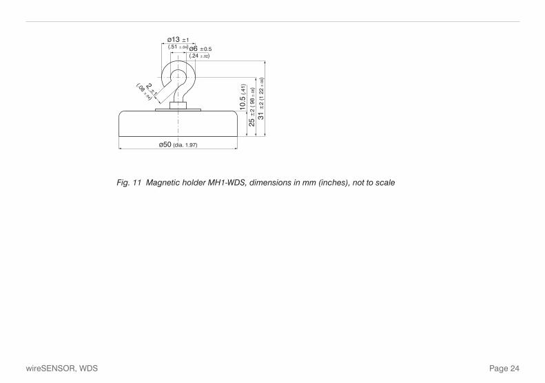
MH1-WDS Magnetic holder with hole for M4 wire coupling, wire clip or attachment head, see Fig. 11
8.5
(.33
)
SW
10
6(.24)
12 (.47)
40 (1.57)
8.3(.33)
55 (
2.17
)
25 (
98)
6.5
(26
)
SW3DIN911
SW3DIN911
2x M4DIN84/912
Adjust the distance, thatthe wire can´t snap off!
Fig. 8 Guide pulley TR1-WDS with mounting socket, dimensions in mm (inches), not to scale

Page 22
wireSENSOR, WDS
ø21 (dia. 0.83)
8 (.
31)
4(.
16)
30 (
1.18
)
26 (1 02)
11 (.43)
14 (
.55)
4(.16)
20 (.79)
Fig. 9 Guide pulley TR3-WDS fix with mounting socket, dimensions in mm (inches), not to scale

Page 23
wireSENSOR, WDS
9.5(.37)
1(.
04)
9(.35)
18 (.71
) ø3(dia. 0.12)
ø0.45(dia 0.02)
40 (
1.57
)25
(.9
8)ø7.5(dia. 0 30)
ø4(dia. 0.16) Ring thickness
2 mm (.51)
xxxx
mm
±1
% ±
10 m
mM
in. l
engt
h: 1
20 (4
.72)
!
Fig. 10 Wire extension WE-xxxx-CLIP, dimensions in mm (inches), not to scale
Page 24
wireSENSOR, WDS
ø50 (dia. 1.97)
10.5
(.4
1)
25 ±
2 (
98 ±
.08)
31 ±
2 (1
22 ±
.08)
ø13 ±1(.51 ±.04) ø6 ±0.5
(.24 ±.02)
2 ±1
(.08 ±.04)
Fig. 11 Magnetic holder MH1-WDS, dimensions in mm (inches), not to scale


MICRO-EPSILON MESSTECHNIK GmbH & Co. KG
Königbacher Str. 15 · 94496 Ortenburg / Germany
Tel. +49 (0) 8542 / 168-0 · Fax +49 (0) 8542 / 168-90
[email protected] · www.micro-epsilon.com
X9751193-A031075GBR
*X9751193-A03*
MICRO-EPSILON MESSTECHNIK