wireless routing
DESCRIPTION
wifiTRANSCRIPT
Router
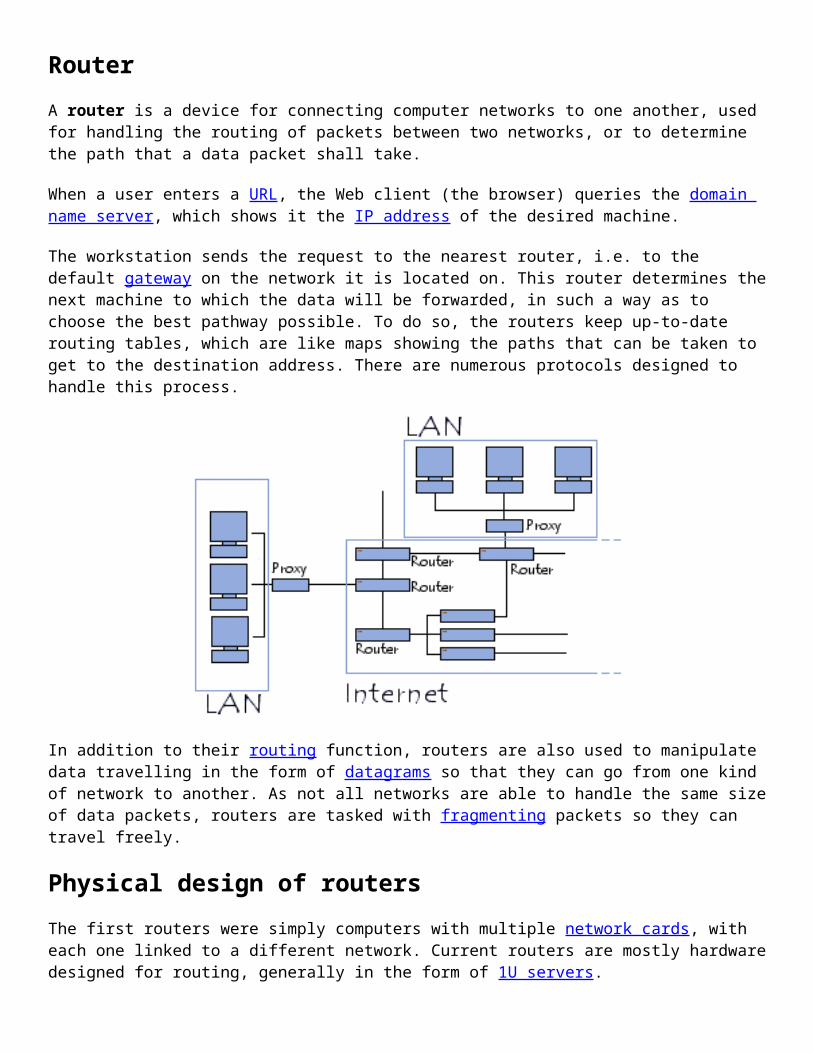
A router is a device for connecting computer networks to one another, used for handling the routing of packets between two networks, or to determine the path that a data packet shall take.
When a user enters a URL, the Web client (the browser) queries the domain name server, which shows it the IP address of the desired machine.
The workstation sends the request to the nearest router, i.e. to the default gateway on the network it is located on. This router determines the next machine to which the data will be forwarded, in such a way as to choose the best pathway possible. To do so, the routers keep up-to-date routing tables, which are like maps showing the paths that can be taken to get to the destination address. There are numerous protocols designed to handle this process.
In addition to their routing function, routers are also used to manipulate data travelling in the form of datagrams so that they can go from one kind of network to another. As not all networks are able to handle the same size of data packets, routers are tasked with fragmenting packets so they can travel freely.
Physical design of routers
The first routers were simply computers with multiple network cards, with each one linked to a different network. Current routers are mostly hardware designed for routing, generally in the form of 1U servers.

A router has several network interfaces, with each one connected to a different network. Therefore, it has one IP address for every network it is connected to.
Wireless router
A wireless router is the same in principle as a traditional router, the difference being that it lets wireless devices (such as WiFi stations) connect to the networks which the router is connected to by wired connections (usually Ethernet).
Routing protocols
There are two major types of routing protocols:
Distance vector routers generate a routing table that calculates the "cost" (in terms of the number of hops) of each route, then sends that table to nearby routers. Each time a connection request is made, the router chooses the least costly route.
Link state routers listen to the network continuously, in order to identify the various elements surrounding it. With this information, each router calculates the shortest pathway (in terms of time) to each neighbouring router, and sends this information in the form of update packets. Finally, each router builds its own routing table by calculating the shortest pathways to all other routers (using the Dijkstra algorithm).

Routers
Routers are devices which make it possible to "choose" the path that datagrams will take to arrive at the destination. They are machines with several network interface cards each one of which is linked to a different network. So, in the simplest configuration, the router only has to "look at" what network a computer is located on to send datagrams to it from the originator.
However, on the Internet the schema is much more complicated for the following reasons:
The number of networks to which a router is connected is generally large The networks to which the router is linked can be linked to other networks that the router cannot see
directly
So, routers work using routing tables and protocols, according to the following model:
The router receives a frame from a machine connected to one of the networks it is attached to Datagrams are sent on the IP layer The router looks at the datagram's header If the destination IP address belongs to one of the networks to which one of the router interfaces is
attached, the information must be sent at layer 4 after the IP header has been unencapsulated (removed) If the destination IP address is part of a different network, the router consults its routing table, a table
which establishes the path to take for a given address. The router sends the datagram using the network interface card linked to the network on which the
router decides to send the packet.
So, there are two scenarios, either the originator and recipient belong to the same network in which case we talk about direct delivery, or there is at least one router between the originator and recipient, in which case we talk about indirect delivery.
In the case of indirect delivery, the role of the router and in particular that of the routing table is very important. So, the operation of a router is determined by the way in which this routing table is created.
If the routing table is entered manually by the administrator, it is a static routing (suitable for small networks)
If the router builds its own routing tables using information that it receives (via the routing protocols), it is a dynamic routing
The routing table
The routing table is a table of connections between the target machine address and the node according to which the router must deliver the message. In reality it is enough that the message is delivered to the network that contains the machine, it is therefore not necessary to store the complete IP address of the machine: only the network identifier of the IP address (i.e. the network ID) needs to be stored.
The routing table is therefore a table which contains address pairs:

Using this table, the router knowing the address of the recipient encapsulated in the message, will be able to find out what interface to send the message on (this comes back to knowing which network interface card to use), and to which router, directly accessible on the network to which this card is connected, to send the datagram. This mechanism consisting of only knowing the address of the next link leading to the destination is called next-hop routing.
However, it may be that the recipient belongs to a non referenced network in the routing table. In this case, the router uses a default router (also called the default gateway).
Here, in a simplified way is what a routing table could look like:
The message is therefore sent from router to router by successive hops, until the recipient belongs to a network directly connected to a router. This then sends the message directly to the target machine...
In the case of static routing, it is the administrator who updates the routing table. In the case of dynamic routing a protocol called a routing protocol enables the automatic updating of the table so that it contains the optimal route at any time.
Routing protocols
The internet is a collection of connected networks. As a result, all routers do not work in the same way, this depends on the type of network upon which they are found.
In fact, there are different levels of routers which operate with different protocols:
Node routers are the main routers because they link the different networks External routers allow a connection to autonomous networks between them. They work with a protocol
called EGP (Exterior Gateway Protocol) which develops gradually by keeping the same name Internal routers allow routing of information inside an autonomous network. They exchange
information using protocols called IGP (Interior Gateway Protocol), such as RIP and OSPF

The RIP protocol
RIP means Routing Information Protocol. It is a Vector Distance type protocol, i.e. each router communicates to the other routers the distance which separates them (the number of hops which separates them). So, when a router receives one of these messages it increments this distance by 1 and sends the message to directly accessible routers. In this way, the routers can then keep the optimal route of a message by storing the next router address in the routing table in such a way that the number of hops to reach a network is kept to a minimum. However this protocol only takes into account the distance between two machines in terms of hops and does not consider the state of the connection so as to select the best possible bandwidth.
The OSPF protocol
OSPF (Open Shortest Path First) is more effective than RIP and is therefore beginning to gradually replace it. It is a protocol route-link type protocol; this means that contrary to RIP, this protocol does not send the number of hops which separates them to the adjacent routers, but the state of the connection which separates them. In this way, each router is capable of sending a card of the state of the network and can as a result choose the most appropriate route for a given message at any time.
In addition, this protocol avoids intermediary routers having to increment the number of hops, which results in much less extensive information making it possible to have more useful bandwidth than with RIP.
The notion of quality of service
The term QoS (an acronym of "Quality of Service") refers to the ability to provide a service (in particular a communication media consistent with requirements in terms of response time and band width).
Applied to packet switching networks (networks based on the use of routers), QoS indicates the ability to be able to guarantee an acceptable level of packet loss.
In fact, contrary to circuit switching networks, such as the switched telephone network, where a communication circuit is always dedicated to communication, it is impossible on the Internet to predict the path taken by the different packets.
So, nothing guarantees that a communication requiring constant bandwidth will be able to take place without incident. That is why there are mechanisms, called QoS mechanisms, making it possible to differentiate different network flows and reserve a share of the bandwidth for those requiring continuous service, without breaks.
Service levels
The term "service level" defines the requirement levels for the capacity of a network to provide a point to point or end to end service with a given traffic. Generally there are three levels of QoS defined:
Best effort provides no differentiation between several network flows and provides no guarantee. This service level is therefore sometimes called lack of QoS.
Differentiated service or soft QoS making it possible to define priority levels for different network flows without however providing a strict guarantee.
Guaranteed service or hard QoS comprising of reserving network resources for certain flow types. The principal mechanism used to obtain such a service level is RSVP (Resource reSerVation Protocol).
Quality of service criteria

The principal criteria enabling quality of service to be assessed are as follows:
Bandwidth: defines the maximum volume of information (bits) per unit of time. Jitter: represents fluctuations in the digital signal, in time or phase. Delay: this characterises the delay between transmission and receipt of a packet. Packet loss: this relates to the non delivery of a data packet, most of the time this is due to network
overload. Desequencing: this is a modification to the arrival order of packets.
The notion of quality of service
The term MPLS (an acronym for "MultiProtocol Label Switching) represents a collection of specifications defined by the IETF (Internet Engineering Task Force) consisting of equipping the frames circulating the network with a label which indicates to the routers the path that the data must follow. So MPLS serves the management of quality of service by defining 5 Classes of Service, known as CoS.
Video. The class of service for transporting video has a higher priority level than classes of service for data.
Voice. The class of service for transporting voice has a priority level equivalent to that of video, i.e. higher than classes of service for data.
High priority data (D1). This is the class of service with the highest priority level for data. It is used in particular for applications which are critical in terms of performance, availability and band width.
Priority data (D2). This class of service relates to non critical applications which have particular requirements in terms of band width,
Non priority data (D3), representing the lowest priority class of service.
MPLS specifications operate at layer 2 of the OSI Model and can notably function on IP, ATM or frame relay networks.
The majority of people, not having lines (cable or Ethernet) linked directly to the Internet, must use telephone lines (the most widely used network) to connect to the Internet. The connection is made using a modem, a device capable of converting digital data from the computer into analogue signals (that can circulate on telephone lines by amplitude or frequency modulation, in the same way as voice when you use the telephone).
Considering that only two computers are communicating and the speed of a telephone line is slow in comparison to that of a local network, it is necessary to use a protocol enabling standard communication between the different machines using a modem, and not overload the telephone line. These protocols are called modem protocols.
The notion of a point to point link
Via a standard telephone line, a maximum of two computers can communicate using a modem, in the same way that it is impossible to call two people simultaneously using the same telephone line. This is thus called a point to point link, i.e. a link between two machines reduced to its most simple expression: there is no need to share the line between several machines, each one speaks and responds in turn.

So, many modem protocols have been developed. The first of them allowed a single transmission of data between two machines, then some of them were equipped with error control and with the growth of the Internet, were equipped with the ability to address machines. In this way, there are now two main modem protocols:
SLIP: an old protocol, low in controls PPP: the most widely used protocol for accessing the Internet via a modem, it authorises addressing
machines
The SLIP protocol
SLIP means Serial Line Internet Protocol. SLIP is the result of the integration of modem protocols prior to the suite of TCP/IP protocols.
It is a simple Internet link protocol conducting neither address or error control, this is the reason that it is quickly becoming obsolete in comparison to PPP.
Data transmission with SLIP is very simple: this protocol sends a frame composed only of data to be sent followed by an end of transmission character (the END character, the ASCII code of which is 192). A SLIP frame looks like this:
Data to be transmitted END
The PPP protocol
PPP means Point to Point Protocol. It is a much more developed protocol than SLIP (which is why it is replacing it), insofar as it transfers additional data, better suited to data transmission over the Internet (the addition of data in a frame is mainly due to the increase in bandwidth).
In reality, PPP is a collection of three protocols:
a datagram encapsulation protocol an LCP, Link Control Protocol, enabling testing and communication configuration a collection of NCPs, Network Control Protocols allowing integration control of PPP within the
protocols of the upper layers
Data encapsulated in a PPP frame is called a packet. These packets are generally datagrams, but can also be different (hence the specific designation of packet instead of datagram). So, one field of the frame is reserved for the type of protocol to which the packet belongs. A PPP frame looks like this:
Protocol (1-2 bytes) Data to be transmitted Padding data
The padding data is used to adapt the length of the frame for certain protocols.

A PPP session (from opening to closure) takes place as follows:
Upon connection, an LCP packet is sent In the event of an authentication request from the server, a packet relating to an authentication protocol
may be sent (PAP, Password Authentication Protocol, or CHAP, Challenge Handshake Authentication Protocol or Kerberos)
Once communication is established, PPP sends configuration information using the NCP protocol Datagrams to be sent are transmitted as packets Upon disconnection, an LCP packet is sent to end the session
What's a wireless network?
A wireless network, as its name suggests, is a network in which two or more terminals (such as laptop computers, PDAs, etc.) can communicate without a hard-wired link.
With wireless networking, a user can stay connected even when moving around within a given geographic area, and this is why the word "mobility" is sometimes used when discussing them.
Wireless networks are based on a link using electromagnetic radiation (radio and infrared) instead of normal cables. There are several different technologies, which differ by the broadcast frequency they use and the range and speed of their transmissions.
Wireless networks are used to make linking remote devices easier over distances from a dozen metres to a few kilometres away. In addition, installing such networks doesn't require any major changes to existing infrastructure, as wired networks do; there's no need to drill holes in walls to drag cables through, and no need for wireways or connectors. This has caused the technology to attain widespread use.
On the other hand, there are some issues regarding the regulation of the radio spectrum. Radio waves are transmitted by many devices (including those used by the military, scientists, and amateurs), but are prone to interference. This is why regulation is needed in every country in order to define which frequency ranges and powers are allowed for each category of use.
In addition, Hertzian waves are not easily confined to a restricted geographic surface. It is therefore easy for a hacker to listen to a network if data is being transmitted unencrypted (as it is by default). Thus, measures must be taken to ensure the privacy of data traveling over wireless networks.
Categories of wireless networks
Normally, wireless networks are classified into one of several categories, depending on the geographic area within which a user may connect to the network (called the coverage area):

Wireless Personal Area Networks (WPAN)
A wireless personal area network (WPAN for short) is a low-range wireless network which covers an area of only a few dozen metres. This sort of network is generally used for linking peripheral devices (like printers, cellphones, and home appliances) or a personal assistant (PDA) to a computer, or just two nearby computers, without using a hard-wired connection. There are several kinds of technology used for WPANs:
The main WPAN technology is Bluetooth, launched by Ericsson in 1994, which offers a maximum throughput of 1 Mbps over a maximum range of about thirty metres. Bluetooth, also known as IEEE 802.15.1, has the advantage of being very energy-efficient, which makes it particularly well-suited to use in small devices.
HomeRF (for Home Radio Frequency), launched in 1998 by HomeRF Working Group (which includes the manufacturers Compaq, HP, Intel, Siemens, Motorola and Microsoft, among others) has a maximum throughput of 10 Mbps with a range of about 50 to 100 metres without an amplifier. The HomeRF standard, despite Intel's support, was abandoned in January 2003, largely because processor manufacturers had started to support on-board Wi-Fi (via Centrino technology, which included a microprocessor and a Wi-Fi adapter on a single component).
The technology ZigBee (also known as IEEE 802.15.4) can be used to connect devices wirelessly at a very low cost and with little energy consumption, which makes it particularly well-suited for being directly integrated into small electronic appliances (like home appliances, stereos, and toys). Zigbee, which operates on the

frequency band of 2.4 GHz and on 16 channels, can reach transfer speeds of up to 250 Kbps with a maximum range of about 100 metres.
Finally, infrared connections can be used to create wireless connections over a few metres, with speeds than can reach a few megabits per second. This technology is widely used in home electronics (like remote controls), but light waves can interfere with the signal. irDA (Infrared Data Association), formed in 1995, has more than 150 members.
Wireless local area networks (WLAN)
A wireless local area network (WLAN for short) is a network covering an area equivalent to that of a business's local network, about a hundred metres in range. It allows terminals within the area of coverage to be linked to one another. There are several different technologies for this:
WiFi (or IEEE 802.11), supported by WECA (Wireless Ethernet Compatibility Alliance) offers a maximum throughput of 54 Mbps over a distance of several hundred metres.
hiperLAN2 (HIgh Performance Radio LAN 2.0) is a European standard developed by ETSI (European Telecommunications Standards Institute). HiperLAN 2 lets users reach speeds of up to 54 Mbps over an area of about a hundred metres, and broadcasts in the frequency range between 5150 and 5300 MHz.
Wireless Metropolitan Area Networks (WMAN)
A Wireless Metropolitan Area Network (WMAN) is also known as a Wireless Local Loop (WLL). WMANs are based on the IEEE 802.16 standard. Wireless local loop can reach effective transfer speeds of 1 to 10 Mbps within a range of 4 to 10 kilometres, which makes it useful mainly for telecommunications companies.
The best-known wireless metropolitan area network is WiMAX, which can reach speeds on the order of 70 Mbps over a radius of several kilometres.
What is WiMAX ?
WiMAX is short for Worldwide Interoperability for Microwave Access. It is a metropolitan wireless standard created by the companies Intel and Alvarion in 2002 and ratified by the IEEE (Institute of Electrical and Electronics Engineers) under the name IEEE-802.16. More precisely, WiMAX is the commercial designation that the WiMAX Forum gives to devices which conform to the IEEE 802.16 standard, in order to ensure a high level of interoperability among them. Devices certified by the WiMAX Forum can carry the following logo:

Goals of WiMAX
The goal of WiMAX is to provide high-speed Internet access in a coverage range several kilometres in radius. In theory, WiMAX provides for speeds around 70 Mbps with a range of 50 kilometres. The WiMAX standard has the advantage of allowing wireless connections between a base transceiver station (BTS) and thousands of subscribers without requiring that they be in a direct line of sight (LOS) with that station. This technology is called NLOS for non-line-of-sight. In reality, WiMAX can only bypass small obstructions like trees or a house and cannot cross hills or large buildings. When obstructions are present, actual throughput might be under 20 Mbps.
Operating principle of WiMAX
At the heart of WiMAX technology is the base transceiver station, a central antenna which communicates with subscribers' antennas. The term point-multipoint link is used for WiMAX's method of communication.
Fixed WiMAX and WiMAX portable
The revisions of the IEEE 802.16 standard fall into two categories:
Fixed WiMAX, also called IEEE 802.16-2004, provides for a fixed-line connection with an antenna mounted on a rooftop, like a TV antenna. Fixed WiMAX operates in the 2.5 GHz and 3.5 GHz frequency bands, which require a licence, as well as the licence-free 5.8 GHz band.
Mobile WiMAX, also called IEEE 802.16e, allows mobile client machines to be connected to the Internet. Mobile WiMAX opens the doors to mobile phone use over IP, and even high-speed mobile services.
Standard Frequency Speed RangeFixed WiMAX (802.16-2004) 2-11 GHz (3.5 GHz in Europe) 75 Mbps 10 kmMobile WiMAX (802.16e) 2-6 GHz 30 Mbps 3.5 km
Applications of WiMAX
One of WiMAX's potential uses is to cover the so-called "last mile" (or "last kilometre) area, meaning providing high-speed Internet access to areas which normal wired technolgies do not cover (such as DSL, cable, or dedicated T1 lines).
Another possibility involves using WiMAX as a backhaul between two local wireless networks, such as those using the WiFi standard. WiMAX will ultimately enable two different hotspots to be linked to create a mesh network.

WiMAX and Quality of Service
The WiMAX standard natively supports Quality of Service (often called QoS for short), the ability to ensure that a service works when used. In practice, WiMAX lets bandwidth be reserved for a given purpose. Some applications cannot work properly when bottlenecks occur. This is the case for Voice Over IP (VOIP), as spoken communication is ineffective when gaps a second long are introduced.
WiMAX Standards
Standard Frequency Status Range
IEEE std 802.16Defines wireless metropolitan area networks (WMANs) on frequency bands higher than 10 GHz.
October 2002
Obsolete
IEEE std 802.16aDefines wireless metropolitan area networks on frequency bands from 2 to 11 GHz inclusive.
October 9, 2003
Obsolete
IEEE 802.16bDefines wireless metropolitan area networks on frequency bands from 10 to 60 GHz inclusive.
Merged with 802.16a (Obsolete)
IEEE std 802.16cDefines options (profiles) for wireless metropolitan area networks in unlicensed frequency bands.
July 2003
IEEE 802.16d (IEEE std 802.16-2004)
Revision incorporating the 802.16, 802.16a, and 802.16c standards.
October 1st, 2004
Active
IEEE std 802.16eAllows wireless metropolitan area networks to be used by mobile clients.
not ratified
IEEE std 802.16fAllows wireless mesh networks to be used.
not ratified

Introduction to Wi-Fi (802.11)
The IEEE 802.11 specification (ISO/IEC 8802-11) is an international standard describing the characteristics of a wireless local area network (WLAN). The name Wi-Fi (short for "Wireless Fidelity", sometimes incorrectly shortened to WiFi) corresponds to the name of the certification given by the Wi-Fi Alliance, formerly WECA (Wireless Ethernet Compatibility Alliance), the group which ensures compatibility between hardware devices that use the 802.11 standard. Today, due to misuse of the terms (and for marketing purposes), the name of the standard is often confused with the name of the certification. A Wi-Fi network, in reality, is a network that complies with the 802.11 standard. Hardware devices certified by the Wi-Fi Alliance are allowed to use this logo:
With Wi-Fi, it is possible to create high-speed wireless local area networks, provided that the computer to be connected is not too far from the access point. In practice, Wi-Fi can be used to provide high-speed connections (11 Mbps or greater) to laptop computers, desktop computers, personal digital assistants (PDAs) and any other devices located within a radius of several dozen metres indoors (in general 20m-50m away) or within several hundred metres outdoors.
Wi-Fi providers are starting to blanket areas that have a high concentration of users (like train stations, airports, and hotels) with wireless networks. These access areas are called "hot spots".
Introduction to Wi-Fi (802.11)
The 802.11 standard reserves the low levels of the OSI model for a wireless connection that uses electromagnetic waves, i.e.:
The physical layer (sometimes shortened to the "PHY" layer), which offers three types of information encoding.
The data link layer, comprised of two sub-layers: Logical Link Control (or LLC) and Media Access Control (or MAC).
The physical layer defines the radio wave modulation and signalling characteristics for data transmission, while the data link layer defines the interface between the machine's bus and the physical layer, in particular an access method close to the one used in the Ethernet standard and rules for communication between the stations of the network. The 802.11 standard actually has three physical layers, which define alternative modes of transmission:
Data Link Layer(MAC)
802.2802.11
Physical Layer(PHY)
DSSS FHSS Infrared
Any high-level protocol can be used on a Wi-Fi wireless network the same way it can be used on an Ethernet network.
The various Wi-Fi standards

The IEEE 802.11 standard is actually only the earliest standard, allowing 1-2 Mbps of bandwidth. Amendments have be made to the original standard in order to optimise bandwidth (these include the 802.11a, 802.11b and 802.11g standards, which are called 802.11 physical standards) or to better specify components in order to ensure improved security or compatibility. This table shows the various amendments to the 802.11 standard and their significance:
Name of standard
Name Description
802.11a Wifi5
The 802.11a standard (called WiFi 5) allows higher bandwidth (54 Mbps maximum throughput, 30 Mbps in practice). The 802.11a standard provides 8 radio channels in the 5 GHz frequency band.
802.11b WiFi
The 802.11b standard is currently the most widely used one. It offers a maximum thoroughput of 11 Mbps (6 Mbps in practice) and a reach of up to 300 metres in an open environment. It uses the 2.4 GHz frequency range, with 3 radio channels available.
802.11cBridging 802.11 and 802.1d
The 802.11c bridging standard is of no interest to the general public. It is only an amended version of the 802.1d standard that lets 802.1d bridge with 802.11-compatible devices (on the data link level).
802.11d Internationalisation
The 802.11d standard is a supplement to the 802.11 standard which is meant to allow international use of local 802.11 networks. It lets different devices trade information on frequency ranges depending on what is permitted in the country where the device is from.
802.11eImproving service quality
The 802.11e standard is meant to improve the quality of service at the level of the data link layer. The standard's goal is to define the requirements of different packets in terms of bandwidth and transmission delay so as to allow better transmission of voice and video.
802.11f Roaming
The 802.11f is a recommendation for access point vendors that allows products to be more compatible. It uses the Inter-Access Point Roaming Protocol, which lets a roaming user transparently switch from one access point to another while moving around, no matter what brands of access points are used on the network infrastructure. This ability is also simply called roaming.
802.11g
The 802.11g standard offers high bandwidth (54 Mbps maximum throughput, 30 Mbps in practice) on the 2.4 GHz frequency range. The 802.11g standard is backwards-compatible with the 802.11b standard, meaning that devices that support the 802.11g standard can also work with 802.11b.
802.11h
The 802.11h standard is intended to bring together the 802.11 standard and the European standard (HiperLAN 2, hence the h in 802.11h) while conforming to European regulations related to frequency use and energy efficiency.

802.11i
The 802.11i standard is meant to improve the security of data transfers (by managing and distributing keys, and implementing encryption and authentication). This standard is based on the AES (Advanced Encryption Standard) and can encrypt transmissions that run on 802.11a, 802.11b and 802.11g technologies.
802.11Ir The 802.11r stadard has been elaborated so that it may use infra-red signals. This standard has become technologically obsolete.
802.11j The 802.11j standard is to Japanese regulation what the 802.11h is to European regulation.
It is also useful to note the existence of a standard called "802.11b+". This is a proprietary standard with improvements in data flow. However, this standard also suffers from gaps in interoperability due to not being an IEEE standard.
Range and data flow
The 802.11a, 802.11b and 802.11g standards, called "physical standards" are amendments to the 802.11 standard and offer different modes of operation, which lets them reach different data transfer speeds depending on their range.
Standard Frequency Speed RangeWiFi a (802.11a) 5 GHz 54 Mbit/s 10 mWiFi B (802.11b) 2.4 GHz 11 Mbit/s 100 mWiFi G (802.11b) 2.4 GHz 54 Mbit/s 100 m
802.11a
The 802.11 standard has a maximum theoretical data flow of 54 Mbps, five times that of 802.11b, but at a range of only about thirty metres. The 802.11a standard relies on a technology called OFDM (Orthogonal Frequency Division Multiplexing). It broadcasts in the 5 GHz frequency range and uses 8 non-overlapping channels.
Because of this, 802.11a devices are incompatible with 802.11b devices. However, there are devices that incorporate both 802.11a and 802.11b chips, called "dual band" devices.
Hypothetical speed(indoors)
Range
54 Mbits/s 10 m48 Mbits/s 17 m36 Mbits/s 25 m24 Mbits/s 30 m12 Mbits/s 50 m6 Mbits/s 70 m
802.11b
The 802.11b standard allows for a maximum data transfer speed of 11 Mbps, at a range of about 100 m indoors and up to 200 metres outdoors (or even beyond that, with directional antennas.)

Hypothetical speedRange
(indoors)Range
(outdoors)11 Mbits/s 50 m 200 m5.5 Mbits/s 75 m 300 m2 Mbits/s 100 m 400 m1 Mbit/s 150 m 500 m
802.11g
The 802.11g standard allows for a maximum data transfer speed of 54 Mbps at ranges comparable to those of the 802.11b standard. What's more, as the 802.11g standard uses the 2.4GHz frequency range with OFDM coding, this standard is compatible with 802.11b devices, with the exception of some older devices.
Hypothetical speedRange
(indoors)Range
(outdoors)54 Mbits/s 27 m 75 m48 Mbits/s 29 m 100 m36 Mbits/s 30 m 120 m24 Mbit/s 42 m 140 m18 Mbit/s 55 m 180 m12 Mbit/s 64 m 250 m9 Mbit/s 75 m 350 m6 Mbit/s 90 m 400 m
There are several kinds of hardware that may be used to implement a WiFi wireless network: Wireless adapters or network interface controllers (NICs for short) are network cards with the 802.11
standard which let a machine connect to a wireless network. WiFi adapters are available in numerous formats, such as PCI cards, PCMCIA cards, USB adapters, and CompactFlash cards. A station is any device that has such a card.
Access points (AP for short; sometimes called hotspots) can let nearby wifi-equipped stations access a wired network to which the access point is directly connected.
The 802.11 standard defines two operating modes:
Infrastructure mode , in which wireless clients are connected to an access point. This is generally the default mode for 802.11b cards.
Ad hoc mode, in which clients are connected to one another without any access point.
Infrastructure mode
In mode infrastructure, each station computer (STA for short) connects to an access point via a wireless link. The set-up formed by the access point and the stations located within its coverage area are called the basic service set, or BSS for short. They form one cell. Each BSS is identified by a BSSID, a 6-byte (48-bite) identifier. In infrastructure mode, the BSSID corresponds to the access point's MAC address.

It is possible to link several access points together (or more precisely several BSS's) using a connection called a distribution system (DS for short) in order to form an extended service set or ESS. The distribution system can also be a wired network, a cable between two access points or even a wireless network.
An ESS is identified with an ESSID (Extended Service Set Identifier), a 32-character identifier (in ASCII format) which acts as its name on the network. The ESSID, often shortened to SSID, shows the network's name, and in a way acts a first-level security measure, since it is necessary for a station to know the SSID in order to connect to the extended network.
When a roaming user goes from one BSS to another while moving within the ESS, his or her machine's wireless network adapter is able to switch access points depending on the quality of the signal it receives from different access points. Access points communicate with one another using a distribution system in order to trade information about the stations and, if necessary, to transmit data from mobile stations. This feature which lets stations move "transparently" from one access point to another is called roaming.
Communicating with the access point

When a station joins a cell, the cell sends a probe request on each channel. This request contains the ESSID that the cell is configured to use, as well as the traffic volume that its wireless adapter can support. If no ESSID is set, the station listens to the network for an SSID.
Each access point broadcasts at regular intervals (about ten times a second) a signal called a beacon, which gives information on its BSSID, its characteristics, and, if applicable, its ESSID. The ESSID is automatically broadcast by default, but it is possible (and recommended) to disable this option.
Whenever a probe request is received, the access point checks the ESSID and the traffic volume request found in the beacon. If the given ESSID matches that of the access point, the acces point sends a response containing synchronisation data and information on its traffic load. This way, the station that receives the response can check the quality of the signal being sent by the access point in order to determine how far away it is. Generally speaking, the closer an access point is, the higher its data transfer capacity is.
So a station within range of multiple access points (which have the same SSID) may choose the access point offering the best balance of capacity and current traffic load.
When a station is within range of several access points, the station chooses which one to connect to.
Ad hoc mode
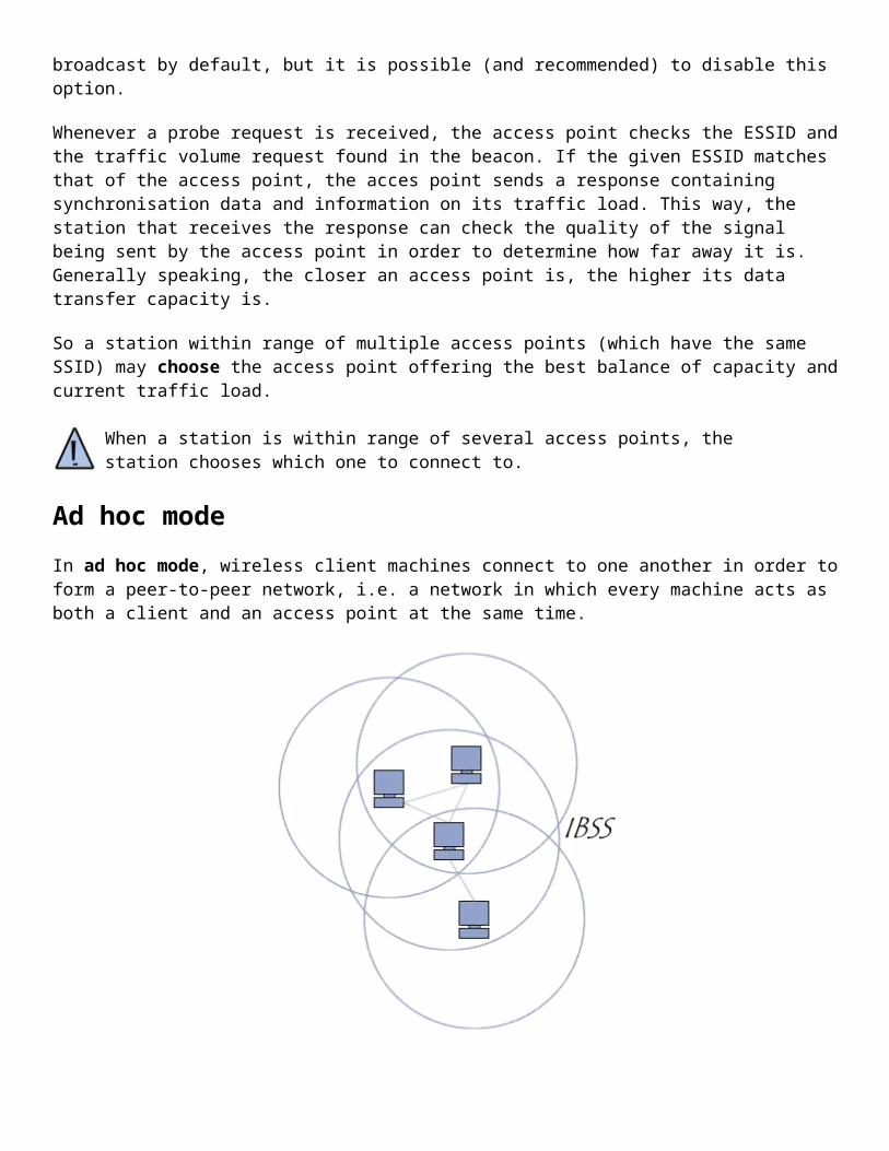
In ad hoc mode, wireless client machines connect to one another in order to form a peer-to-peer network, i.e. a network in which every machine acts as both a client and an access point at the same time.
The set-up formed by the stations is called the independent basic service set, or IBSS for short.
An IBSS is a wireless network which has at least two stations and uses no access point. The IBSS therefore forms a temporary network which lets people in the same room exchange data. It is identified by an SSID, just like an ESS in infrastructure mode.

In an ad hoc network, the range of the independent BSS is determined by each station's range. That means that if two of the stations on the network are outside each other's range, they will not be able to communicate, even if they can "see" other stations. Unlike infrastructure mode, ad hoc mode has no distribution system that can send data frames from one station to another. An IBSS, then, is by definition a restricted wireless network.
Lack of security
Radio waves intrinsically have the power to propagate in all directions, with a relatively wide range. Because of this, it is very difficult to keep radio broadcasts confined to a limited area. Radio propagation also occurs three-dimensionally. The waves can therefore travel from one floor of a building to another (albeit with a high degree of attenuation.)
The main consequence of this "wild propagation" of radio waves is that a non-authorised person may be able to listen to the network, possibly beyond the enclosure of the building where the wireless network is set up.
The critical issue is that a wireless network can very easily be installed in a business without the IT department even knowing! An employee only has to plug an access point into a data port for all communication on the network to become "public" throughout the access point's broadcast range.
War-driving
Given how easy it is to "listen" to wireless networks, some people have taken to travelling around a city with a wireless-compatible laptop computer (or PDA) looking for wireless networks. This practice is called war driving (sometimes written wardriving or war-Xing for "war crossing"). Specialised war-driving software allows the locations of these open access points to be mapped accurately with the help of a Global Positionning System (GPS).
These maps can show available unsecured wireless networks, sometimes allowing people to access the Internet. Many websites have been started to share this information; in fact, in 2002, students in London invented a sort of "sign language" to indicate the presence of wireless networks in an area by drawing symbols on the sidewalk in chalk. This is called "warchalking". Two opposing semicircles mean that the area is covered by an open network that provides Internet access, a circle indicates the presence of an open wireless network without access to a wired network, and a W inside a circle shows that there is a properly secured wireless network.
Security risks
There are several risks involved in not properly securing a wireless network:
Data interception is the practice of listening in on the transmissions of various wireless network users.

Cracking is an attempt to access a local network or the Internet. Transmission jamming means sending out radio signals so as to interfere with traffic. Denial of service attacks make the network unusable by sending out false requests.
Data interception
By default, a wireless network is unsecured. This means that it is open to everyone, and anyone within the coverage area of an access point may potentially listen to communications being sent on the network. For an individual, there is little threat, as data is rarely confidential, unless the data is of a personal nature. For a business, however, this may pose a serious problem.
Network intrusion
When an access point is installed on a local network, it lets any station access the wired network, as well as the Internet, if the local network is connected to it. For this reason, an unsecured wireless network gives hackers the perfect gateway to an business or organisation's internal network.
Besides letting the hacker steal or destroy information on the network and giving him or her free Internet access, the wireless network might also be helping him or her to carry out cyber-attacks. Indeed, since there is no way to identify a hacker on a network, the business which installed the wireless network might be held responsible for the attack.
Radio jamming
Radio waves are very sensitive to interference. This is why a signal can easily be jammed by a radio transmission with a frequency close to that used by the wireless network. Even a simple microwave oven can make a wireless network completely inoperable if it is being used within an access point's range.
Denial of service
The 802.11 standard's network access method is based on the CSMA/CA protocol, which involves waiting until the network is free before transmitting data frames. Once the connection is established, a station must be linked to an access point in order to send it packets. Because the methods for accessing a network and associating with it are known, it is easy for a hacker to sent packets requesting for a station to become disassociated from the network. Sending out information intended to disrupt a wireless network is called a denial of service attack.
What's more, connecting to wireless networks uses up power. Even if the wireless peripheral devices have power-saving features, a hacker may be able to send enough encrypted data to a machine for it to overload. Many portable peripherals (like PDAs and laptop computers) have limited battery life. Therefore, a hacker may want to cause excessive power consumption that renders the device temporarily unusable, which is called a battery exhaustion attack.
Adapted infrastructure
The first thing to do when a wireless network is installed is to place the access points in reasonable locations depending on the desired area of coverage. However, it is not uncommon to find that the covered area ends up being larger than desired, in which case it is possible to reduce the access terminal's strength so that its broadcast range matches the coverage area

Avoid using default values
When an access point is first installed, it is configured to certain default values, including the administrator's password. Many novice administrators think that once the network is operational, there is no point in changing the access point's configuration. However, the default settings offer only a minimal level of security. For this reason, it is vital to log in to the administration interface (generally via a web interface or by using a particular port on the access terminal), especially to set an administrative password.
What's more, in order to connect to an access point, it is necessary to know the network identifier (SSID). This is why it is strongly recommended to change the default name of the network and to deactivate broadcasting the name on the network. Changing the default network identifier is all the more important because it can, if left unaltered, give hackers information on the brand or model of the access point being used.
Filtering MAC addresses
Every network adapter (the generic term for a network card) has its own physical address (called a MAC address). This address is represented by 12 digits in hexadecimal format, split up into two-digit groups separated by dashes.
The configuration interfaces of access points generally allow them to keep a list of access permissions (called the ACL, for Access Control List) based on the MAC addresses of the devices authorised to connect to the wireless network.
This somewhat restrictive precaution allows the network to limit access to a certain number of machines. However, this does not solve the problem of securing data transfers.
WEP - Wired Equivalent Privacy
To solve transfer security issues on wireless networks, the 802.11 standard includes a simple data encryption mechanism called WEP (Wired equivalent privacy).
WEP is an 802.11 data frame encryption protocol that uses the symmetrical algorithm RC4 with 64-bit or 128-bit keys. The concept of WEP involves setting a secret 40-bit or 128-bit key ahead of time. This secret key must be declared on both the access point and the client machines. The key is used to create a pseudo-random number of the same length as the data frame. Each data transmission is encrypted this way, by using the pseudo-random number as a "mask"; an "Exclusive OR" operation is used to combine the frame and the pseudo-random number into an enciphered datastream.
The session key shared by all stations is static, which means that to deploy a large number of WiFi stations, they must be configured using the same session key. Therefore, knowing the key is all that is needed to decrypt the signals.
Furthermore, 24 bits of the key are used only for initialisation, which means that only 40 bits of a 64-bit key, or 104 bits of a 128-bit key, are actually used for encryption.
For a 40-bit key, a brute force attack (which tries all possible keys) might not stop a hacker from quickly finding the session key. Also, a flaw detected by Fluhrer, Mantin and Shamir in the generation of the pseudo-random stream makes it possible for the session key to be discovered by storing and analysing 100 MB to 1 GB of traffic.

Therefore, WEP is insufficient for actually ensuring data privacy. Nevertheless, it is strongly recommended to use at least a 128-bit WEP key to ensure a minimum level of privacy. This can reduce the risk of intrusion by 90%.
Improve authentication
In order to more effectively manage authentication, authorisation, and accounting(AAA for short), a RADIUS server (Remote Authentication Dial-In User Service) may be used. The RADIUS protocol (defined by RFCs 2865 and 2866) is a client/server system which lets user accounts and related access permissions be centrally managed.
Setting up a VPN
For all communications which require a high level of security, it is better to use strong encryption of data by installing a virtual private network (VPN).
The concept of virtual private networks
Local area networks (LANs) are the internal networks of organisations, meaning connections between the machines that belong to a particular organisation. These networks are becoming more and more frequently connected to the Internet, using interconnection equipment. Very often, companies have a need to communicate over the Internet with subsidiaries, customers, or even staff who may be geographically distant.
However, data transmitted through the Internet is much more vulnerable than when it is travelling over an organisation's internal network, as the path taken is not defined in advance, which means that the data has to go through a public network infrastructure belonging to different entities. For this reason, it is not impossible that somewhere along the line, a nosy user might listen to the network or even hijack this signal. Therefore, information which is sensitive for an organisation or business should not be sent under such conditions.
The first solution to fulfill this need for secure communications involves linking remote networks using dedicated lines. However, as most businesses aren't able to link two remote local area networks with a dedicated line, it is sometimes necessary to use the Internet as a transmission medium.
A good compromise involves using the Internet as a transmission medium with a tunneling protocol, which means that the data is encapsulated before being sent in an encrypted manner. The term Virtual Private Network (VPN for short) is used to refer to the network artificially created in this way. This network is said to be virtual because it links two "physical" networks (local area networks) using an unreliable connection (the Internet), and private because only computers which belong to a local area network on one end of the VPN or the other can "see" the data.
The VPN system, then, can provide a secure connection at a lower cost, as all that is needed is the hardware on either end. On the other hand, it cannot ensure a quality of service comparable to a leased line, as the physical network is public and therefore not guaranteed.
Operation of a VPN
A virtual private network relies on a protocol called a tunneling protocol; that is, a protocol that encrypts the data which runs from one end of the VPN to the other.

The word "tunnel" is used to symbolise the fact that, between the moment the data enters the VPN and when it leaves, it is encrypted, and therefore incomprehensible to anyone not located at either end of the VPN, as if the data were travelling through a tunnel. In a two-machine VPN, the VPN client is the part which encrypts and decrypts the data on the user's end, and the VPN server (or more often remote access server) is the element that decrypts the data on the organisation's end.
That way, whenever a user needs to access the virtual private network, his/her request is transmitted unencrypted to the gateway system, which connects to the remote network using the public network's infrastructure as an intermediary, then transmits the request in an encrypted manner. The remote computer then provides the data to the VPN server on its network, which sends the reply encrypted. When the user's VPN client receives the data, it is decrypted, and finally sent to the user.
Tunneling protocols
The main tunneling protocols are:
PPTP (Point-to-Point Tunneling Protocol) is a layer 2 protocol developed by Microsoft, 3Com, Ascend, US Robotics and ECI Telematics.
L2F (Layer Two Forwarding) is a layer 2 protocol developed by Cisco, Northern Telecom and Shiva. It is now nearly obsolete.
L2TP (Layer Two Tunneling Protocol), the outcome of work by the IETF (RFC 2661), brings together the features of PPTP and L2F. It is a layer 2 protocol based on PPP.
IPSec is a layer 3 protocol created by the IETF that can send encrypted data for IP networks.
The PPTP protocol
The principle of PPTP (Point To Point Tunneling Protocol) involves creating frames with the protocol PPP and encapsulating them using an IP datagram.
Thus, with this kind of connection, remote machines on two local area networks are connected with a point to point connection (including an authentication/encryption system), and the packet is sent within an IP datagram.
This way, the local area network's data (as well as the addresses of the machines found in the message's header) is encapsulated within a PPP message, which is itself encapsulated within an IP message.
The L2TP protocol
L2TP is a standard tunneling protocol (standardised in an RFC) which is very similar to PPTP. L2TP encapsulates PPP frames, which are themselves encapsulating other protocols (such as IP, IPX or NetBIOS).
The IPSec protocol
IPSec is a protocol defined by the IETF which is used to make data transfers secure on the network layer. It is actually a protocol which makes security improvements to the IP protocol in order to ensure the privacy, integrity, and authentication of data sent.
IPSec is based around three modules:
IP Authentication Header (AH), which involves integrity, authentication and protection from replay attacks on packets.
Encapsulating Security Payload (ESP), which defines packet encryption. ESP provides privacy, integrity, authentication and protection against replay attacks.
Security Association (SA) which defines key exchange and security settings. SAs include all information on how to process IP packets (the AH and/or ESP protocols, tunnel or transportation mode, the security algorithms used by the protocols, the keys used, etc.) The key exchange is done either manually or with the exchange protocol IKE (most of the time), which enables both parties to hear one another.
Introduction to WPA
WPA (WiFi protected Access) WiFi network security solution offered by the WiFi Alliance, in order to fill gaps in WEP.
WPA - WiFi Protected Access
WPA is a "light" version of the 802.11i protocol, which relies on authentication protocols and a strong encryption algorithm: TKIP (Temporary Key Integrity Protocol). TKIP generates keys randomly and can alter an encryption key several times a second, for greater security.
WPA requires installing an authentication server (most commonly a RADIUS server), which identifies users on a network and sets their access privileges. Nonetheless, small networks can make use of a simpler version of WPA, called WPA-PSK, by deploying the same encryption key on all devices, which eliminates the need for a RADIUS server.
WPA (in its first build) only supports networks in infrastructure mode, which means it cannot be used to secure wireless peer-to-peer networks (ad hoc mode).
There are several kinds of hardware that may be used to implement a WiFi wireless network: Wireless adapters or network interface controllers (NICs for short) are network cards with the 802.11
standard which let a machine connect to a wireless network. WiFi adapters are available in numerous formats, such as PCI cards, PCMCIA cards, USB adapters, and CompactFlash cards. A station is any device that has such a card.

Access points (AP for short; sometimes called hotspots) can let nearby wifi-equipped stations access a wired network to which the access point is directly connected.
The 802.11 standard defines two operating modes:
Infrastructure mode , in which wireless clients are connected to an access point. This is generally the default mode for 802.11b cards.
Ad hoc mode, in which clients are connected to one another without any access point.
Infrastructure mode
In mode infrastructure, each station computer (STA for short) connects to an access point via a wireless link. The set-up formed by the access point and the stations located within its coverage area are called the basic service set, or BSS for short. They form one cell. Each BSS is identified by a BSSID, a 6-byte (48-bite) identifier. In infrastructure mode, the BSSID corresponds to the access point's MAC address.
It is possible to link several access points together (or more precisely several BSS's) using a connection called a distribution system (DS for short) in order to form an extended service set or ESS. The distribution system can also be a wired network, a cable between two access points or even a wireless network.

An ESS is identified with an ESSID (Extended Service Set Identifier), a 32-character identifier (in ASCII format) which acts as its name on the network. The ESSID, often shortened to SSID, shows the network's name, and in a way acts a first-level security measure, since it is necessary for a station to know the SSID in order to connect to the extended network.
When a roaming user goes from one BSS to another while moving within the ESS, his or her machine's wireless network adapter is able to switch access points depending on the quality of the signal it receives from different access points. Access points communicate with one another using a distribution system in order to trade information about the stations and, if necessary, to transmit data from mobile stations. This feature which lets stations move "transparently" from one access point to another is called roaming.
Communicating with the access point
When a station joins a cell, the cell sends a probe request on each channel. This request contains the ESSID that the cell is configured to use, as well as the traffic volume that its wireless adapter can support. If no ESSID is set, the station listens to the network for an SSID.
Each access point broadcasts at regular intervals (about ten times a second) a signal called a beacon, which gives information on its BSSID, its characteristics, and, if applicable, its ESSID. The ESSID is automatically broadcast by default, but it is possible (and recommended) to disable this option.
Whenever a probe request is received, the access point checks the ESSID and the traffic volume request found in the beacon. If the given ESSID matches that of the access point, the acces point sends a response containing synchronisation data and information on its traffic load. This way, the station that receives the response can check the quality of the signal being sent by the access point in order to determine how far away it is. Generally speaking, the closer an access point is, the higher its data transfer capacity is.
So a station within range of multiple access points (which have the same SSID) may choose the access point offering the best balance of capacity and current traffic load.

When a station is within range of several access points, the station chooses which one to connect to.
Ad hoc mode
In ad hoc mode, wireless client machines connect to one another in order to form a peer-to-peer network, i.e. a network in which every machine acts as both a client and an access point at the same time.
The set-up formed by the stations is called the independent basic service set, or IBSS for short.
An IBSS is a wireless network which has at least two stations and uses no access point. The IBSS therefore forms a temporary network which lets people in the same room exchange data. It is identified by an SSID, just like an ESS in infrastructure mode.
In an ad hoc network, the range of the independent BSS is determined by each station's range. That means that if two of the stations on the network are outside each other's range, they will not be able to communicate, even if they can "see" other stations. Unlike infrastructure mode, ad hoc mode has no distribution system that can send data frames from one station to another. An IBSS, then, is by definition a restricted wireless network.
Introduction to 802.11i
802.11i was ratified on 24 June 2004, in order to address security issues in WiFi networks. Like WPE, it relies on the TKIP encryption algorithm, but it also supports the much more secure AES (Advanced Encryption Standard).
The Wi-Fi Alliance created a new certification, called WPA2, for devices that support the 802.11i standard (like laptop computers, PDAs, network cards, etc.)

Unlike WPA, WPA2 can secure wireless networks in infrastructure mode as well as networks in ad hoc mode.
WPA Architectures
The IEEE 802.11i standard defines two operating modes:
WPA-Personal: This mode allows for the implementation of a secure infrastructure based on WPA without having to implement an authentication server. WPA-Personal rests on the use of a shared key, called PSK for Pre-shared Key, which is stored at both the access point and the client devices. Unlike WEP, it is not necessary to enter a key of pre-defined length. WPA lets the user enter a passphrase, which a hash algorithm then converts into a PSK.
WPA-Enterprise: Enterprise mode requires 802.1x authentication infrastructure using an authentication server, generally a RADIUS server (which stands for Remote Authentication Dial-in User Service), and a network controller (the access point).
Introduction to 802.1X
The 802.1x standard is a security solution ratified by the IEEE in June 2001 which can authenticate (identify) a user who wants to access a network (whether wired or wireless). This is done through the use of an authentication server.
802.1x is based on the EAP protocol (Extensible Authentication Protocol), as defined by the IETF. This protocol is used for transporting user identification information.
EAP
The EAP protocol is centred around the use of an access controller called an authenticator, which either grants or denies a user access to the network. The user in this system is called a supplicant. The access controller is a basic firewall which acts as an intermediary between the user and an authentication server, and requires very few resources to function. For a wireless network, the access point acts as the authenticator.
The authentication server (sometimes called the NAS, for Network Authentication Service or Network Access Service) can approve the user's identity as transmitted by the network controller, and then grant the user access depending on his or her credentials. What's more, this type of server can store and keep track of information related to the users. In the case of a service provider, for example, these features allow the server to bill them based on how long they were connected or how much data they transferred.
The authentication server is most commonly a RADIUS server (Remote Authentication Dial-In User Service), a standard authentication server defined by RFC 2865 and 2866, but any other authentication service may be used instead.
The following is a summary of how a secure network using the 802.1x standard works:
1. The access controller, having previously received a connection request from the user, sends an identification request;
2. The user sends a response to the access controller, which routes the response to the authentication server;

3. The authentication server sends a "challenge" to the access controller, which transmits it to the user. The challenge is a method of establishing identification. If the client cannot evaluate the challenge, the server tries another one, and so on;
4. The user responds to the challenge. If the user's identity is correct, the authentication server sends approval to the access controller, which allows the user onto the network or part of the network, depending on the rights granted. If the user's identity could not be verified, the authentication server sends a refusal message, and the access controller denies the user access to the network.
Encryption key exchange
Besides authenticating users, the 802.1x standard provides users with a secure way to exchange encryption keys, in order to improve overall security.