wireless pick and place robotic arm
TRANSCRIPT

PICK AND PLACE ROBOTIC ARM
Submitted in partial fulfillment of requirements for the degree of
BACHELOR OF TECHNOLOGY
By
Ayush Verma, Dheeraj Bumb and Kratika Goyal
ID’s- 11EJCEC039, 11EJCEC048& 11EJCEC070
Under the supervision of
Prof. Reema Agarwal
Professor, EC&E(JECRC, Jaipur)
DEPARTMENT OF ELECTRONICS & COMMUNICATION ENGINEERING
JAIPUR ENGINEERING COLLEGE AND RESEARCH CENTRE, JAIPUR
MAY 2015
1

ACKNOWLEDGEMENT
Words cannot suffice to even begin to show the gratitude we owe to the
people who helped me in this project but we will give it my best try.
First of all we would like to thank my supervisor, Prof.
ReemaAgarwal, Department of Electronics and Communication, Jaipur
Engineering College and Research Center, Jaipur of whom we are highly
indebted for her invaluable technical guidance and moral support during
the project work. This work could not have attained its present shape
without her generous help, invaluable suggestions, initiative & keen
interest in this work.
We would also like to extend my sincere gratitude to IndraSen Sir
for taking out time from his busy schedule and teaching us the basic
working and coding of ATmega16 for our project. Without his help
ATMEGA16 wouldn’t have been such a smooth platform to work upon.
We also take this opportunity to offer my sincere and whole hearted
gratitude Balram Sir for his constant motivation and support during the
course of the entire project.
We would also like to extend my thanks to my friends and
colleagues for helping me all the times and being very supportive.
Without all of you, this project would not have seen the light of the day.
2

ABSTRACT
Mankind has always strived to give life like qualities to its artifacts in an attempt to
find substitutes for himself to carry out his orders and also to work in a hostile
environment. The popular concept of a robot is of a machine that looks and works like
a human being.
The industry is moving from current state of automation to Robotization, to increase
productivity and to deliver uniform quality. The industrial robots of today may not
look the least bit like a human being although all the research is directed to provide
more and more anthropomorphic and humanlike features and super-human
capabilities in these.
One type of robot commonly used in industry is a robotic manipulator or simply a
robotic arm. It is an open or closed kinematic chain of rigid links interconnected by
movable joints. In some configurations, links can be considered to correspond to
human anatomy as waist, upper arm and forearm with joint at shoulder and elbow. At
end of arm a wrist joint connects end effectors which may be a tool and its fixture or a
gripper or any other device to work.
Here how a pick and place robot can be designed for a workstation where loading and
packing of lead batteries is been presented. All the various problems and obstructions
for the loading process has been deeply analyzed and been taken into consideration
while designing the pick and place pick and place robot.
3

CONTENTS
TITLE…………………………………………………………………………..1
ABSTRACT…………………………………………………………………….2
ACKNOWLEDGEMENT……………………………………………………..3
TABLE OF CONTENT………………………………………………………..4
LIST OF FIGURE……………………………………………………………...6
CHAPTER ONE…………………………………………………………………8
1.1INTRODUCTION TO PICK AND PLACE ROBOT………………………8
1.2 TYPES OF ROBOT…………………………………………………………9
1.3 AIM………………………………………………………………………….11
1.4 OBJECTIVE…………………………………………………………………11
1.5 SCOPE……………………………………………………………………….11
1.6 INTRODUCTION TO EMBEDDED SYSTEM…………………………….12
CHAPTER TWO…………………………………………………………………14
2.1 ATMEGA16 MICROCONTROLLER………………………………………14
2.2 HARDWARE COMPONENT EXPLANATION…………………………...15
2.3 CIRCUIT DIAGRAM……………………………………………………….35
CHAPTER THREE……………………………………………………………....36
3.1WORKING PROCEDURE………………………………………………….36
3.2 COSTING DETAILS………………………………………………………...42
4

CHAPTER FOUR ……………………………………………………………….43
4.1SOFTWARE TOOLS………………………………………………………...43
4.2 SAFETY REQUIREMENT’S………………………………………………..46
CONCLUSION AND FUTURE SCOPE………………………………………47
REFERENCE……………………………………………………………………48
APPENDIX A………………………………………………………..49
Datasheet of L293D IC………………………………………………………………………………………………….
APPENDIX B……………………………………………………….52
Datasheet of 7805 IC……………………………………………………………………………………………………..
5

6

LIST OF FIGURE
FIG 1.1 INDUSTRIAL ROBOT
FIG1.2 AGRICULTURE ROBOT
FIG1.3 TELE ROBOT
FIG1.4 HUMAN ROBOT
FIG1.5 BLOCK DIAGRAM OF EMBEDED SYSTEM
FIG2.1 PIN DIAGRAM OF ATMEGA16
FIG2.2 ATMEGA16 IC
FIG2.3 TYPICAL CRSTAL OSCILLATOR
FIG2.4 PULLUP RESISTOR
FIG2.5 ELECTROLYTIC CAPACITOR
FIG2.6 BASE IC OF 8PIN AND 40 PIN
FIG2.7 RESISTOR
FIG2.8 VOLTAGE REGULATOR
FIG2.9 IC HT12E
FIG2.10 RF TRANSMITTER
FIG2.11 RF RECEIVER
FIG2.12 IC HT12D
FIG2.13 PIN DIAGRAM OF L293D
FIG2.14 CIRCUIT DIAGRAM OF H BRIDGE
FIG 2.15 BLOCKS DIAGRAM OF L293D
FIG 2.16 DC MOTOR
FIG2.17 GRIPPER
7
FIG2.18 LIFTER ASSEMBLY
FIG2.19 TRACK WHEEL
FIG2.20 METTALIC CHASIS
FIG2.21 BATTERY
FIG2.22 CONNCTION DIAGRAM OF CIRCUIT
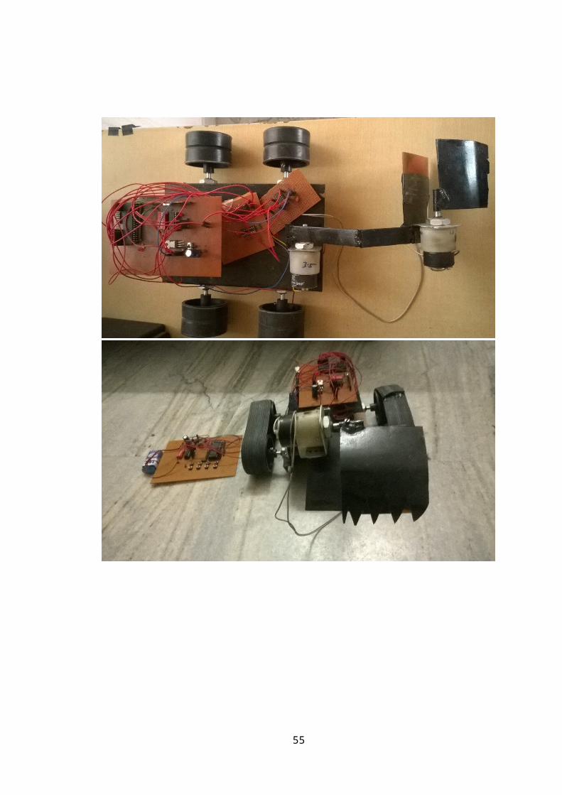
FIG3.1 COMPLETE PROJECT
8

CHAPTER -1
1.1 INTRODUCTION TO PICK AND PLACE ROBOT
Mechanical is the branch of engineering science & Technology related to
machinery, and their design, manufacture, application, and structural disposition.
Robotics is related to electronics, mechanics, and software. Robotics research today is
focused on developing systems that exhibit modularity, flexibility, redundancy, fault-
tolerance, a general and extensible software environment and seamless connectivity to
other machines, some researchers focus on completely automating a manufacturing
process or a task, by providing sensor based intelligence to the mechanical arm, while
others try to solidify the analytical foundations on which many of the basic concepts
in robotics are built.
In this highly developing society time and man power are critical constrains
for completion of task in large scales. The automation is playing important role to
save human efforts in most of the regular and frequently carried works. One of the
major and most commonly performed works is picking and placing of jobs from
source to destination.
Present day industry is increasingly turning towards computer-based
automation mainly due to the need for increased productivity and delivery of end
products with uniform quality. The inflexibility and generally high cost of hard-
automation systems, which have been used for automated manufacturing tasks in the
past, have led to a broad based interest in the use of mechanical arm capable of
performing a variety of manufacturing functions in a flexible environment and at
lower costs.The use of Industrial mechanical arm characterizes some of contemporary
trends in automation of the manufacturing process.However, present day industrial
mechanical arm also exhibit a monolithic mechanical structure and closed-system
software architecture.They are concentrated on simple repetitive tasks, which tend not
to require high precision.
The pick and place mechanical arm is a human controlled based system that
detects the object, picks that object from source location and places at desired
location. For detection of object, human detect presence of object and move machine
accordingly.
9

FIG 1.1 INDUSTRIAL ROBOT
FIG 1.2 AGRICULTURAL ROBOT
FIG 1.3 TELE ROBOT
Industrial robots are found in a variety of locations including the automobile and
manufacturing industries. Robots cut and shape fabricated parts, assemble machinery
and inspect manufactured parts. Some types of jobs robots do: load bricks, die cast,
drill, fasten, forge, make glass, grind, heat treat, load/unload machines, machine parts,
handle parts, measure, monitor radiation, run nuts, sort parts, clean parts, profile
objects, perform quality control, rivet, sand blast, change tools and weld.
Outside the manufacturing world robots perform other important jobs. They can be
found in hazardous duty service, CAD/CAM design and prototyping, maintenance
jobs, fighting fires, medical applications, military warfare and on the farm.
1.2 TYPES OF ROBOTS AS PER APPLICATIONS
Nowadays, robots do a lot of different tasks in many fields.
And this number of jobs entrusted to robots is growing steadily.
That's why one of the best ways how to divide robots into types is
a division by their application.
1.2.1 INDUSTRIAL ROBOTS: Robots today are being utilized
in a wide variety of industrial applications. Any job that involves
repetitiveness, accuracy, endurance, speed, and reliability can be
done much better by robots, which is why many industrial jobs
that used to be done by humans are increasingly being done by
robots.
1.2.2 MOBILE ROBOTS: Also known as Automated Guided
Vehicles, or AGVs, these are used for transporting material over
large sized places like hospitals, container ports, and warehouses,
using wires or markers placed in the floor, or lasers, or vision, to
sense the environment they operate in. An advanced form of the
AGV is the SGV, or the Self Guided Vehicle, like Patrol Bot
Gofer, Tug, and Specie-Minder, which can be taught to
autonomously navigate within a space.
1.2.3 AGRICULTURE ROBOTS: Although the idea of robots
planting seeds, ploughing fields, and gathering the harvest may
10
seem straight out of a futuristic science fiction book, nevertheless there are several
robots in the experimental stages of being used for agricultural purposes, such as
robots that can pick apples.
1.2.4 TELEROBOTS: These robots are used in places that are hazardous to humans,
or are inaccessible or far away. A human operator located at a distance from a Tele
robot controls its action, which was accomplished with the arm of the space shuttle.
Telerobots are also useful in nuclear power plants where they, instead of humans, can
handle hazardous material or undertake operations potentially harmful for humans.
1.2.5 SERVICE ROBOTS: The Japanese are in the forefront in these types of robots.
Essentially, this category comprises of any robot that is used outside an industrial
facility, although they can be sub-divided into two main types of robots: one, robots
used for professional jobs, and the second, robots used for personal use. Amongst the
former type are the above mentioned robots used for military use, and then there are
robots that are used for underwater jobs, or robots used for cleaning hazardous waste,
like.
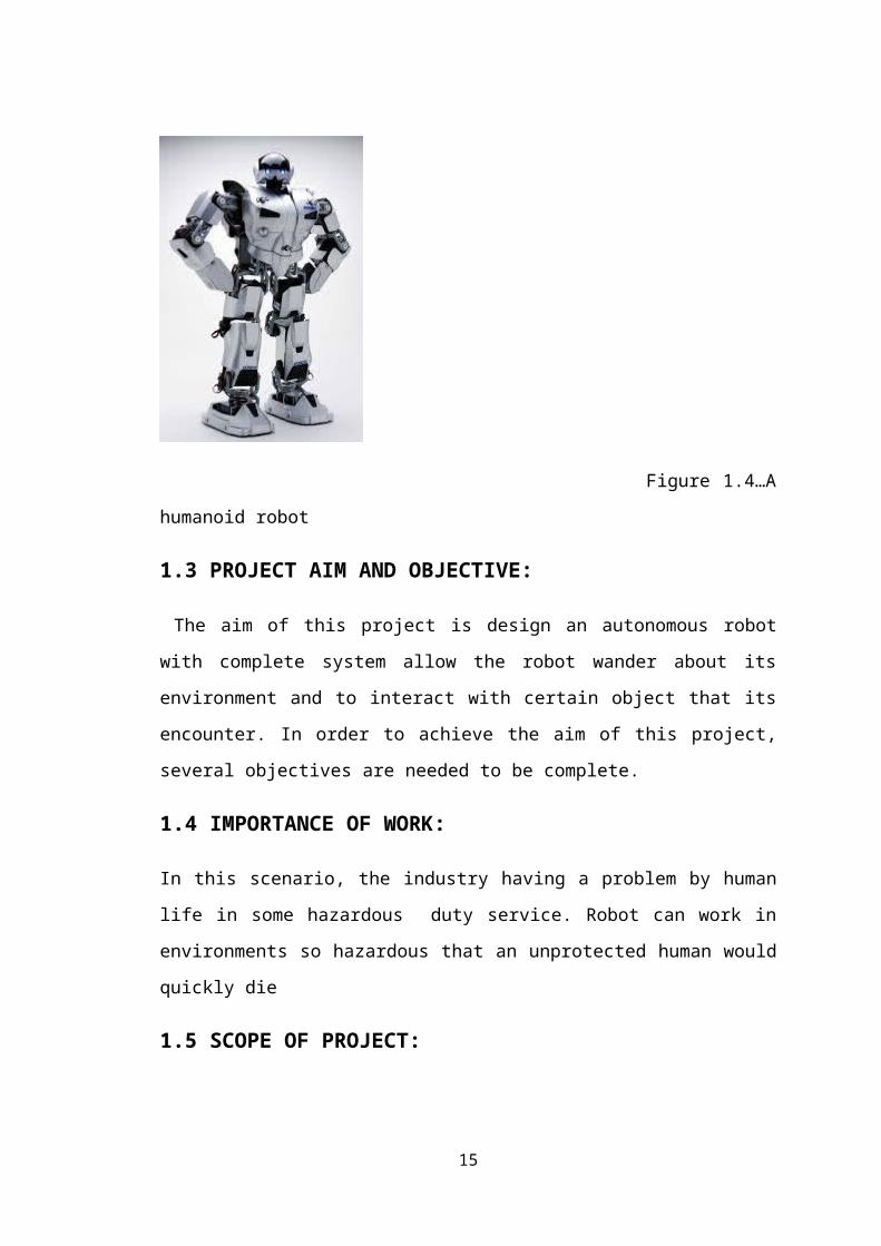
HUMANOID ROBOT : A humanoid robot is a robot with its body shape built to
resemble that of the human body. A humanoid design might be for resemble humans
functional purposes, such as interacting with human tools and environments, for
experimental purposes, such as the study of bipedal locomotion, or for other purposes.
In general, humanoid robots have a torso, a head, two arms, and two legs, though
some forms of humanoid robots may model only part of the body, for example, from
the waist up. Some humanoid robots may also have heads designed to replicate human
facial features such as eyes and mouths. Androids are humanoid robots built to
aesthetically.
11

Figure 1.4…A humanoid robot
1.3 PROJECT AIM AND OBJECTIVE:
The aim of this project is design an autonomous robot with complete system allow the
robot wander about its environment and to interact with certain object that its
encounter. In order to achieve the aim of this project, several objectives are needed to
be complete.
1.4 IMPORTANCE OF WORK:
In this scenario, the industry having a problem by human life in some hazardous duty
service. Robot can work in environments so hazardous that an unprotected human
would quickly die
1.5 SCOPE OF PROJECT:
Industrial automation, equipment and goods carrier, tour guide in museum, deliver the
mail in office building, delivers medication in the hospital, can be used in place of
crane in various lifting and carriage application.
12

Embedded System
Software Hardware
ALPCVB Etc.,
ProcessorPeripheralsmemory
1.6 INTRODUCTION TO EMBEDDED SYSTEMS
An embedded system is a system which is going to do a predefined specified task is
the embedded system and is even defined as combination of both software and
hardware. A general-purpose definition of embedded systems is that they are devices
used to control, monitor or assist the operation of equipment, machinery or plant.
"Embedded" reflects the fact that they are an integral part of the system. At the other
extreme a general-purpose computer may be used to control the operation of a large
complex processing plant, and its presence will be obvious.
All embedded systems are including computers or microprocessors. Some of these
computers are however very simple systems as compared with a personal computer.
The simplest devices consist of a single microprocessor (often called a "chip”), which
may itself be packaged with other chips in a hybrid system or Application Specific
Integrated Circuit (ASIC). Its input comes from a detector or sensor and its output
goes to a switch or activator which (for example) may start or stop the operation of a
machine.
Figure: 1.5 Block diagram of Embedded System
13

Embedded consist of both software and hardware:
Memory: It is used to store data or address.
Peripherals: These are the external devices connected
Processor: It is an IC which is used to perform some task
Applications of embedded systems
Manufacturing and process control
Construction industry
Transport
Buildings and premises
Domestic service
Communications
Office systems and mobile equipment
Banking, finance and commercial
Medical diagnostics, monitoring and life support
Testing, monitoring and diagnostic systems
14
CHAPTER – 2
HARDWARE DISCRIPTION
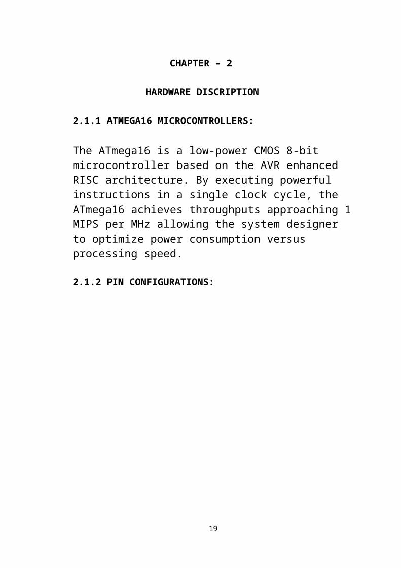
2.1.1 ATMEGA16 MICROCONTROLLERS:
The ATmega16 is a low-power CMOS 8-bit microcontroller based on the AVR enhanced RISC architecture. By executing powerful instructions in a single clock cycle, theATmega16 achieves throughputs approaching 1 MIPS per MHz allowing the system designer to optimize power consumption versus processing speed.
2.1.2 PIN CONFIGURATIONS:
15

FIGURE 2.1 PIN DIAGRAM ATMEGA16
FIGURE2.2ATMEGA16 IC
2.2.1 Standard Features:
Advanced RISC Architecture– 131 Powerful Instructions – Most Single-clock Cycle Execution– 32 x 8 General Purpose Working Registers– Fully Static Operation– Up to 16 MIPS Throughput at 16 MHz– On-chip 2-cycle Multiplier• Nonvolatile Program and Data Memories– 16K Bytes of In-System Self-Programmable FlashEndurance: 10,000 Write/Erase Cycles– Optional Boot Code Section with Independent Lock BitsIn-System Programming by On-chip Boot ProgramTrue Read-While-Write Operation– 512 Bytes EEPROMEndurance: 100,000 Write/Erase Cycles– 1K Byte Internal SRAM– Programming Lock for Software Security• JTAG (IEEE std. 1149.1 Compliant) Interface– Boundary-scan Capabilities According to the JTAG Standard– Extensive On-chip Debug Support– Programming of Flash, EEPROM, Fuses, and Lock Bits through the JTAG Interface• Peripheral Features– Two 8-bit Timer/Counters with Separate Prescalers and Compare Modes– One 16-bit Timer/Counter with Separate Prescaler, Compare Mode, and CaptureMode– Real Time Counter with Separate Oscillator– Four PWM Channels– 8-channel, 10-bit ADC
Programmable Serial USART– Master/Slave SPI Serial Interface– Programmable Watchdog Timer with Separate On-chip Oscillator– On-chip Analog Comparator• Special Microcontroller Features
16

– Power-on Reset and Programmable Brown-out Detection– Internal Calibrated RC Oscillator– External and Internal Interrupt Sources– Six Sleep Modes: Idle, ADC Noise Reduction, Power-save, Power-down, Standbyand Extended Standby• I/O and Packages– 32 Programmable I/O Lines– 40-pin PDIP, 44-lead TQFP, and 44-pad MLF• Operating Voltages– 2.7 - 5.5V for ATmega16L– 4.5 - 5.5V for ATmega16• Speed Grades– 0 - 8 MHz for ATmega16L– 0 - 16 MHz for ATmega16
2.2.2 PIN DESCRIPTION
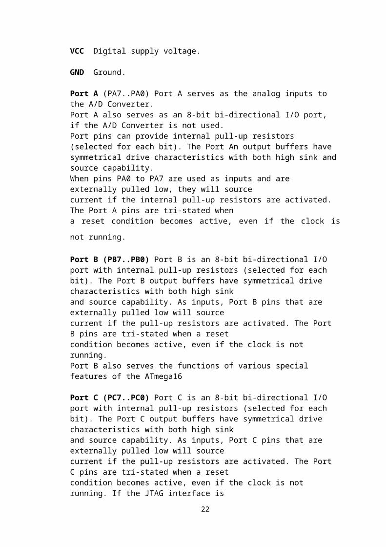
VCC Digital supply voltage.
GND Ground.
Port A (PA7..PA0) Port A serves as the analog inputs to the A/D Converter.Port A also serves as an 8-bit bi-directional I/O port, if the A/D Converter is not used.Port pins can provide internal pull-up resistors (selected for each bit). The Port An output buffers have symmetrical drive characteristics with both high sink and source capability.When pins PA0 to PA7 are used as inputs and are externally pulled low, they will sourcecurrent if the internal pull-up resistors are activated. The Port A pins are tri-stated whena reset condition becomes active, even if the clock is not running.
Port B (PB7..PB0) Port B is an 8-bit bi-directional I/O port with internal pull-up resistors (selected for eachbit). The Port B output buffers have symmetrical drive characteristics with both high sinkand source capability. As inputs, Port B pins that are externally pulled low will sourcecurrent if the pull-up resistors are activated. The Port B pins are tri-stated when a resetcondition becomes active, even if the clock is not running.Port B also serves the functions of various special features of the ATmega16
Port C (PC7..PC0) Port C is an 8-bit bi-directional I/O port with internal pull-up resistors (selected for eachbit). The Port C output buffers have symmetrical drive characteristics with both high sinkand source capability. As inputs, Port C pins that are externally pulled low will sourcecurrent if the pull-up resistors are activated. The Port C pins are tri-stated when a reset
17

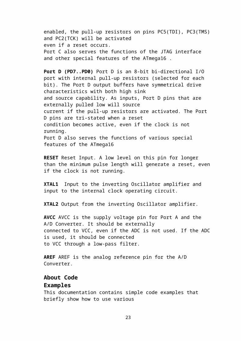
condition becomes active, even if the clock is not running. If the JTAG interface isenabled, the pull-up resistors on pins PC5(TDI), PC3(TMS) and PC2(TCK) will be activatedeven if a reset occurs.Port C also serves the functions of the JTAG interface and other special features of the ATmega16 .
Port D (PD7..PD0) Port D is an 8-bit bi-directional I/O port with internal pull-up resistors (selected for eachbit). The Port D output buffers have symmetrical drive characteristics with both high sinkand source capability. As inputs, Port D pins that are externally pulled low will sourcecurrent if the pull-up resistors are activated. The Port D pins are tri-stated when a resetcondition becomes active, even if the clock is not running.Port D also serves the functions of various special features of the ATmega16
RESET Reset Input. A low level on this pin for longer than the minimum pulse length will generate a reset, even if the clock is not running.
XTAL1 Input to the inverting Oscillator amplifier and input to the internal clock operating circuit.
XTAL2 Output from the inverting Oscillator amplifier.
AVCC AVCC is the supply voltage pin for Port A and the A/D Converter. It should be externallyconnected to VCC, even if the ADC is not used. If the ADC is used, it should be connectedto VCC through a low-pass filter.
AREF AREF is the analog reference pin for the A/D Converter.
About CodeExamplesThis documentation contains simple code examples that briefly show how to use variousparts of the device. These code examples assume that the part specific header file isincluded before compilation. Be aware that not all C Compiler vendors include bit definitionsin the header files and interrupt handling in C is compiler dependent. Pleaseconfirm with the C Compiler documentation for more details.
18
2.2.3 CRYSTAL OSILLATOR
A crystal oscillator is an electronic oscillator circuit that uses the
mechanical resonance of a vibrating crystal of piezoelectric material to create an
electrical signal with a very precise frequency. This frequency is commonly used to
keep track of time (as in quartz wristwatches), to provide a stable clock
signal for digital integrated circuits, and to stabilize frequencies for radio
transmitters and receivers. The most common type of piezoelectric resonator used is
the quartz crystal, so oscillator circuits incorporating them became known as crystal
oscillators, but other piezoelectric materials including polycrystalline ceramics are
used in similar circuits.
Quartz crystals are manufactured for frequencies from a few tens of kilohertz to
hundreds of megahertz. More than two billion crystals are manufactured annually.
Most are used for consumer devices such as wristwatches, clocks, radios, computers,
and cell phones. Quartz crystals are also found inside test and measurement
equipment, such as counters, signal generators, and oscilloscopes.
A crystal is a solid in which the constituent atoms, molecules, or ions are packed in a
regularly ordered, repeating pattern extending in all three spatial dimensions.
Almost any object made of an elastic material could be used like a crystal, with
appropriate transducers, since all objects have natural resonant frequencies
of vibration. For example, steel is very elastic and has a high speed of sound. It was
often used in mechanical filters before quartz. The resonant frequency depends on
size, shape, elasticity, and the speed of sound in the material. High-frequency crystals
are typically cut in the shape of a simple, rectangular plate. Low-frequency crystals,
such as those used in digital watches, are typically cut in the shape of a tuning fork.
For applications not needing very precise timing, a low-cost ceramic resonator is often
used in place of a quartz crystal.
19

When a crystal of quartz is properly cut and mounted, it can be made to distort in
an electric field by applying a voltage to an electrode near or on the crystal. This
property is known as electrostriction or inverse piezoelectricity. When the field is
removed, the quartz will generate an electric field as it returns to its previous shape,
and this can generate a voltage. The result is that a quartz crystal behaves like a circuit
composed of an inductor, capacitor and resistor, with a precise resonant frequency.
Quartz has the further advantage that its elastic constants and its size change in such a
way that the frequency dependence on temperature can be very low. The specific
characteristics will depend on the mode of vibration and the angle at which the quartz
is cut (relative to its crystallographic axes). Therefore, the resonant frequency of the
plate, which depends on its size, will not change much, either. This means that a
quartz clock, filter or oscillator will remain accurate. For critical applications the
quartz oscillator is mounted in a temperature-controlled container, called a crystal
oven, and can also be mounted on shock absorbers to prevent perturbation by external
mechanical vibrations.
Figure 2.3diagram of typical crystal oscillator generating a frequency of 11.0592
MHz
2.2.4 CERAMIC CAPACITOR:
A ceramic capacitor is a fixed value capacitor in which ceramic material acts as the
dielectric. It is constructed of two or more alternating layers of ceramic and a
20

metal layer acting as the electrode The composition of the ceramic material defines
the electrical behavior and therefore applications. Ceramic capacitors are divided into
two application classes:
Class 1 ceramic capacitors offer high stability and low losses for resonant
circuit applications.
Class 2 ceramic capacitors offer high volume efficiency for buffer, by-pass and
coupling applications.
Ceramic capacitors, especially the multilayer style (MLCC), are the most produced
and used capacitors in electronic equipment that incorporate approximately one
trillion pieces (1000 billion pieces) per year.
Ceramic capacitors of special shapes and styles are used as capacitors for RFI/ MFI
suppression, as feed-through capacitors and in larger dimensions as power capacitors
for transmitter
2.2.5 Pull-up resistor:
Pull up resistor are used in electronic logic circuits to ensure that inputs to logic
systems settle at expected logic levels if external devices are disconnected or high
impedance is introduced. They may also be used at the interface between two different
types of logic devices, possibly operating at different power supply voltages
When the switch is open the voltage of the gate input is pulled up to the level of Vin.
When the switch is closed, the input voltage at the gate goes to ground.
A pull-up resistor weakly "pulls" the voltage of the wire it is connected to towards its
voltage source level when the other components on the line are inactive. When all
other connections on the line are inactive, they are high-impedance and act like they
are disconnected. Since the other components act as though they are disconnected, the
circuit acts as though it is disconnected, and the pull-up resistor brings the wire up to
the high logic circuits When another component on the line goes active, it will
override the high logic level set by the pull-up resistor. The pull-up resistor ensures
that the wire is at a defined logic level even if no active devices are connected to it.
21
A pull-down resistor works in the same way but is connected to ground. It holds the
logic signal near zero volts when no other active device is connected.
.
Figure 2.4 pull up resistor
ELECTROLYTIC CAPACITOR: electrolytic capacitor is a capacitor that uses
an electrolytic (an ionic conducting liquid) as one of its plates to achieve a larger
capacitance per unit volume than other types. The large capacitance of electrolytic
capacitors makes them particularly suitable for passing or bypassing low-frequency
signals and storing large amounts of energy. They are widely used in power supply
and interconnecting stages of amplifiers at audio frequencies. An electrolytic capacitor
will generally have higher leakage current than a comparable (dry) capacitor, and may
have significant limitations in its operating temperature range, parasitic resistance and
inductance, and the stability and accuracy of its capacitance value.
FIGURE 2.5 A Electrolytic capacitor
22
2.2.7 BASES OF IC : IC sockets are generally for preventing damage to IC's from
soldering and while testing multiple circuits. These are made from Black
Thermoplastic and tin-plated alloy contacts. One end is notched to aid in
identification. They can be mounted end to end to suit longer IC's
Figure 2.6 base of 40 and 8 pin respectively
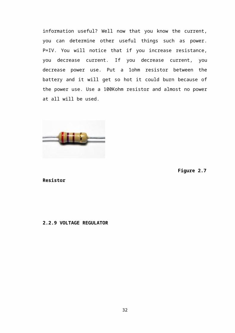
2.2.8 RESISTOR: These do exactly what they say, they resist the flow of electron.
These are necessary for several reasons. They control how much current goes down to
each wire. They control the power uses. They can control voltages (since current,
resistance)
The last point is important as it is the basis of Ohm's law, V=IR. Voltage = Current x
Resistance. For example, suppose you take a resistor and connect the two ends of a
battery with it. You know that your battery is 9V (or whatever) and you know the
resistor is 3Kohm (determined by the color stripes on the resistor), so 9V divided by
3Kohm is .003amps (3 milliamps). So why is this information useful? Well now that
you know the current, you can determine other useful things such as power. P=IV.
You will notice that if you increase resistance, you decrease current. If you decrease
23
current, you decrease power use. Put a 1ohm resistor between the battery and it will
get so hot it could burn because of the power use. Use a 100Kohm resistor and almost
no power at all will be used.
Figure 2.7 Resistor
2.2.9 VOLTAGE REGULATOR
Figure 2.8 voltage regulator IC 7805
24

A voltage regulator is an electrical regulator designed to automatically maintain a
constant voltage level. It may use an electromechanical mechanism, or passive or
active electronic components. Depending on the design, it may be used to regulate one
or more AC or DC voltages. There are two types of regulator are they.
Positive Voltage Series (78xx) and
Negative Voltage Series (79xx)
78xx: ’78’ indicate the positive series and ‘xx’indicates the voltage rating. Suppose
7805 produces the maximum 5V.’05’indicates the regulator output is 5V.
79xx: ’78’ indicate the negative series and ‘xx’indicates the voltage rating.
Suppose 7905 produces the maximum -5V.’05’indicates the regulator output is -5V.
These regulators consists the three pins there are
Pin1: It is used for input pin.
Pin2: This is ground pin for regulator
Pin3: It is used for output pin. Through this pin we get the output.
2.2.10 ENCODER IC (HT12E)
HT12E is a remote control encoder paired with HT12D utilizing CMOS technology. It
encodes data and address pins into serial coded waveform suitable for RF or IR
modulation. HT12E has a maximum of 12 bits of tri-state address pins providing up to
312 address codes; thereby, drastically reducing any code collision and unauthorized
code scanning possibilities. The pin description is shown below. It has 4 input while 1
output pin. The address pins can also be utilized as data pins.
25
Figure 2.9 HT12E IC
PIN NO. SYMBOL FUNCTION
1-8 A0-A7 Address pins
9 Vss Ground pin
13-10 D0-D3 Output pins
14 TE Enables the transmission
15-16 Osc1-Osc2 R-osc of 470K ohm is connected
17 Dout Output for transmission
18 Vcc 5V supply voltage
Table 3-3 Pin description for HT12E
26

2.2.11 RF MODULE (Rx/Tx)
Radio frequency (RF) is a rate of oscillation in the range of about 3 KHz to 300 GHz,
which corresponds to the frequency of radio waves, and the alternating currents which
carry radio signals.
Although radio frequency is a rate of oscillation, the term "radio frequency" or its
abbreviation "RF" are also used as a synonym for radio – i.e. to describe the use of
wireless communication, as opposed to communication via electric wires
The RF module is working on the frequency of 315 MHz and has a range of 50-80 meters.
Figure 2.10 RF Transmitter
PIN FUNCTION
VCC 5V supply
GND Ground pin
Data Input from pin 17 of HT12E for data transmission
Ant A wire attached here works as an antenna
Table 3-3 Pin description for RF Tx
27
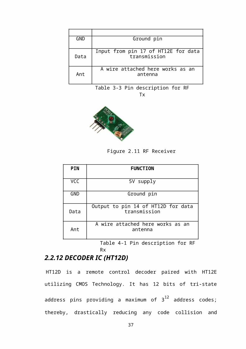
Figure 2.11 RF Receiver
2.2.12 DECODER IC (HT12D)
HT12D is a remote control decoder paired with HT12E utilizing CMOS Technology.
It has 12 bits of tri-state address pins providing a maximum of 312 address codes;
thereby, drastically reducing any code collision and unauthorized code scanning
possibilities. The input data is decoded when no error or unmatched codes are found.
It has 1 input while 4 output pins. The address pins can also be utilized as data pins.
Figure 2.12 HT12D IC
28
PIN FUNCTION
VCC 5V supply
GND Ground pin
Data Output to pin 14 of HT12D for data transmission
Ant A wire attached here works as an antenna
Table 4-1 Pin description for RF Rx

PIN NO. SYMBOL FUNCTION
1-8 A0-A7 Address pins
9 Vss Ground pin
13-10 D0-D3 Output pins
14 Din Input from RF
15-16 Osc1-Osc2 Rosc of 470K ohm is connected
17 VT Indicates valid transmission
18 Vcc 5V supply voltage
Table 4-2 Pin description for HT12D
2.2.13 L293D( H-BRIDGE):
4 5 12 13
16 8
1
2
15
9
7
10
314
6
11
VCC1- LOGIC SUPPLY= 5V
LM+ OUTPUT FOR MOTOR1
OUTPUT FOR MOTOR2
L_IN1
L_EN
GND
L293DINPUT LINES
R_EN
L_IN2
R_IN2
R_IN1
LM-
RM+
RM-
Figure 2.13 PIN DIAGRAM OF L293D IC
29

Motor are arrange in a fashion called H bridge. H bridge is an electronics circuits
which enables a voltage to be applied across the load in either direction. It allow a
circuit full control, that is an H bridge, a microcontroller logic chip, or remote control
can electronically command the motor to go forward ,reverse and brake
An H-bridge is an electronic circuit which enables DC electric motors to be run
forwards or backwards. These circuits are often used in robotics. H-bridges are
available as integrated circuits, or can be built from discrete components.
Figure 2.14 circuit diagram of H bridge
The two basic states of a H-bridge. The term "H-bridge" is derived from the typical
graphical representation of such a circuit. An H-bridge is built with four switches
(solid-state or mechanical). When the switches S1 and S4 (according to the first
figure) are closed (and S2 and S3 are open) a positive voltage will be applied across
the motor. By opening S1 and S4 switches and closing S2 and S3 switches, this
voltage is reversed, allowing reverse operation of the motor.
Using the nomenclature above, the switches S1 and S2 should never be closed at the
same time, as this would cause a short circuit on the input voltage source. The same
applies to the switches S3 and S4. This condition is known as shoot-through.
2.2. 13.1 OPERATION
The H-Bridge arrangement is generally used to reverse the polarity of the motor, but
can also be used to 'brake' the motor, where the motor comes to a sudden stop, as the
motors terminals are shorted, or to let the motor 'free run' to a stop, as the motor is
effectively disconnected from the circuit. The following table summarizes operation.
30

S1 S2 S3 S4 Result
1 0 0 1 Motor moves right
0 1 1 0 Motor moves left
0 0 0 0 Motor free runs
0 1 0 1 Motor brakes
Table: 2.2 H-bridge switch operation
2. 2.13.2 H-BRIDGE DRIVER
The switching property of this H-Bridge can be replaced by a Transistor or a Relay or
A Mosfet or even by an IC. Here we are replacing this with an IC named L293D as
the driver whose description is as given below. The Device is a monolithic integrated
high voltage, high current four channel driver designed to accept standard DTL or
TTL logic levels and drive inductive loads as and switching power transistors. To
simplify use as two bridges each pair of channels is equipped with an enable input. A
separate supply input is provided for the logic, allowing operation at a lower voltage
and internal clamp diodes are included. This device is suitable for use in switching
applications at frequencies up to 5 kHz. The L293D is assembled in a 16 lead plastic
package which has 4 center pins connected together and used for heat sinking The
L293D is assembled in a 20 lead surface mount which has 8 center pins connected
together and used for heat sinking.
31
2.2.13.3 FEATURES
600mA OUTPUT CURRENT CAPABILITY
PER CHANNEL
1.2A PEAK OUTPUT CURRENT (non repetitive)
ENABLE FACILITY
OVERTEMPERATURE PROTECTION
LOGICAL "0" INPUT VOLTAGE UP TO 1.5 V
(HIGH NOISE IMMUNITY)
INTERNAL CLAMP DIODES
2.2.13.4 BLOCK DIAGRAM:
Figure 2.15 block diagram of LM293D
2.2. 14 DC MOTORS:
These are very commonly used in robotics. DC motors can rotate in both directions
depending upon the polarity of current through the motor. These motors have free
running torque and current ideally zero. These motors have high speed which can be
reduced with the help of gears and traded off for torque. Speed Control of DC motors
is done through Pulse Width Modulation techniques, i.e. sending the current in
intermittent bursts. PWM can be generated by 555 timer IC with adjusted duty cycle.
Varying current through the motor varies the torque.
32

FIGURE 2.16 (DC MOTOR
GRIPPER ARM: The gripper module is state of the art robotic arm which can be
used in various 'pick and place' kind of robots. It works on DC Motor (9 to 12V
DC).
Change in rotation direction of the DC Motor, generates Jaw Open & Close
Action.
The DC motor can be easily be controlled with the help of DPDT Switch (manual
mode) or with the help of any micro controller along with L293D Motor Driver
module.
FIGURE 2.17 Gripper Arm
33

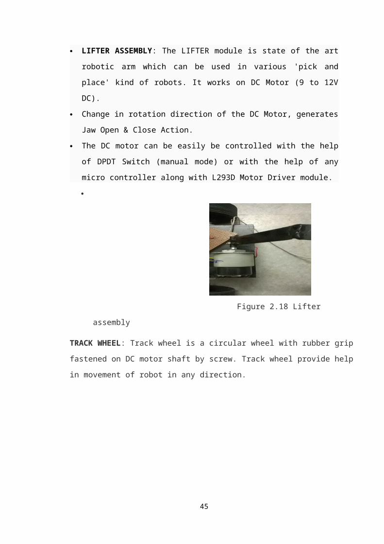
LIFTER ASSEMBLY: The LIFTER module is state of the art robotic arm which
can be used in various 'pick and place' kind of robots. It works on DC Motor (9 to
12V DC).
Change in rotation direction of the DC Motor, generates Jaw Open & Close
Action.
The DC motor can be easily be controlled with the help of DPDT Switch (manual
mode) or with the help of any micro controller along with L293D Motor Driver
module.
Figure 2.18 Lifter assembly
TRACK WHEEL: Track wheel is a circular wheel with rubber grip fastened on DC motor
shaft by screw. Track wheel provide help in movement of robot in any direction.
Figure 2.19 Track wheel
34

CHASSIS: A chassis consists of an internal framework that supports a man-made
object in its construction and use. It is analogous to an animal's skeleton. An example
of a chassis is the under part of a motor vehicle, consisting of the frame (on which the
body is mounted). Here metallic chassis is used.
FIGURE 2.20 A metallic chassis
POWER SUPPLY: To provide energy to DC motors for movement of robot A
Battery of DC (6 volt to 12 V, 4.5A) is being used.
Figure 2.21 Battery
35

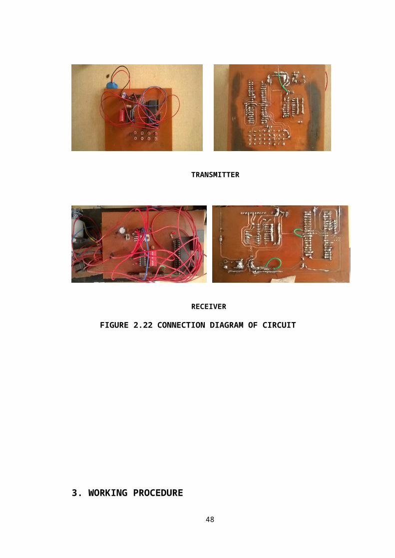
2.3 CIRCUIT DIAGRAM:
TRANSMITTER
RECEIVER
FIGURE 2.22 CONNECTION DIAGRAM OF CIRCUIT
36
3. WORKING PROCEDURE
3.1 WORKING
Pick and Place Robots can be mounted on a stand to allow the robots to access the entire working envelope. Product will enter the robotic work envelope after its orientation has been identified by an upstream vision system. Using custom end of arm tool, the product will be picked and placed by the robot at the desired location.
Wireless Communication
The wireless control systems have become an essential part of everyday life ranging from garage door
openers to smart metering systems. The communication in such systems involves transfer of
information from a controller to a remote robot without any physical connections.
There are quite a large number of wireless data communications systems available in the developing
world today ranging from short distance to long distance communications involving RF, GSM, GPS,
IR, Bluetooth and Zigbee technologies. At present, the RF communication is very important to transfer
information over a short distance. This RF technology enables public or private radio communications
with wireless networking features.
What is a Remote Robot?
A remote robot is a device that is able to move and interact with the external control. Remote control
robots can perform a wide range of functions by simply following remote control commands. Remote
robots are placed and operated in hazardous and dangerous environments where human beings are
restricted owing to the dangers associated with such places.
37

Pick and Place Remote Robot
Remote robots consist of transmitter and receiver modules. The transmitter module creates
electromagnetic waves in a particular frequency range and the receiver module receives these signals.
The microcontroller decodes these signals and uses them to control the other peripherals of robot like
arms, wheels, etc.
There are several varieties of remote robots available such as firefighting robot, spy-control robot and
metal detector robot, etc. The subsequent paragraphs provide information about advanced pick and
place remote robots that are used in many industries for lifting heavy weights, and such robots are
based on RF communication technology.
Pick and Place Remote Robot
Description
A pick and place robot speeds up the process of choosing an object and placing it in the desired location
and thus increases the production rate. It can be used in surveillance, and can also be used to pick up
harmful objective like bombs and then to diffuse them safely. It is a cylindrical robot that possesses
movements like forward, backward, left and right based on the RF commands.
Working Procedure of the Pick and Place Remote robot
In this system, a pick and place robot is controlled with the push-buttons arranged in the remote. On
pressing a corresponding button, a command signal is transmitted to the robot such that the robot moves
in the appropriate direction. This project consists of two blocks: transmitter and receiver block. The
commands send by a user from the transmitter block are received by the receiver block to perform
desired actions.
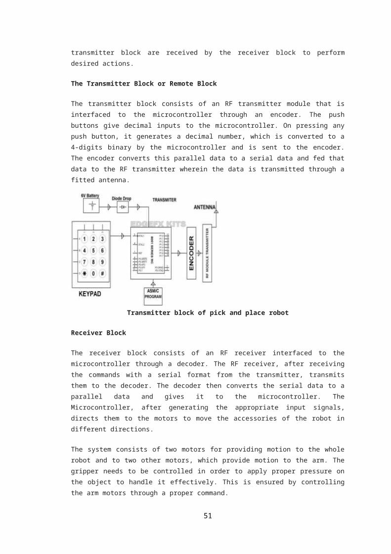
The Transmitter Block or Remote Block
The transmitter block consists of an RF transmitter module that is interfaced to the microcontroller
through an encoder. The push buttons give decimal inputs to the microcontroller. On pressing any push
button, it generates a decimal number, which is converted to a 4-digits binary by the microcontroller
and is sent to the encoder. The encoder converts this parallel data to a serial data and fed that data to the
RF transmitter wherein the data is transmitted through a fitted antenna.
38

Transmitter block of pick and place robot
Receiver Block
The receiver block consists of an RF receiver interfaced to the microcontroller through a decoder. The
RF receiver, after receiving the commands with a serial format from the transmitter, transmits them to
the decoder. The decoder then converts the serial data to a parallel data and gives it to the
microcontroller. The Microcontroller, after generating the appropriate input signals, directs them to the
motors to move the accessories of the robot in different directions.
The system consists of two motors for providing motion to the whole robot and to two other motors,
which provide motion to the arm. The gripper needs to be controlled in order to apply proper pressure
on the object to handle it effectively. This is ensured by controlling the arm motors through a proper
command.
Receiver block of pick and place robot
Short Description on Radio Frequency Technology (RF)
39

The RF communication is a short distance communication that consists of a receiver and a transmitter
module. The transmitter creates a magnetic wave at a particular frequency and the receiver takes this
signal. The microcontroller decodes this signal and uses it to control other peripherals.
Generally, the RF module works with SUB-GHz and GHz frequencies. The following SUB-GHz
frequency RF module works with 433MHz frequency and operates within a voltage range of 3 to 12v.
RF Transmitter and Receiver
As compared to the other radio-frequency devices, the performance of an RF module depends on
several factors like transmitting power because increasing the transmitter’s power results in large
communication distance coverage. However, this may result in high electrical power drain on the
transmitter device, which causes shorter operating life of the battery powered devices. And also, the
usage of this device at a higher transmitted power creates interference with other RF devices.
Applications of Pick and Place robot
Medical Applications: These robots can be used in various surgical operations like in joint
replacement operations, orthopedic and internal surgery operations. They perform the operations with
more precision and accuracy.
Industrial Applications: These robots are used in manufacturing segments to pick up the required
parts and place them in correct positions to complete the machinery fixture. They can also be used to
place objects on a conveyer belt as well as to pick up defective products from the conveyer belt.
Defense Applications: They can be used for robot performed military applications such as surveillance
and also to pick up harmful objects like bombs and diffuse them safely.
A Pick and Place Robots find its use in different factories, automobile industries, in making and packaging drugs, textiles and foods and recently in chocolate factories for assembling and packaging.
40

But the most important of all the applications of Pick and Place Robots is considered in DEFENCE where a remotely Guided robot with a Video Camera and small Shot Gun, can be sent to investigate and defuse possible bombs (BOMB DISPOSAL).
A Robot named BOMB BUSTER is currently in use across many country for diffusing and detonating bombs, either by blasting with water, firing them with a shotgun or placing other bombs bearby them.
Robots can also venture into dangerously polluted areas as chemical spills and radioactive zones such as in nuclear power plants.
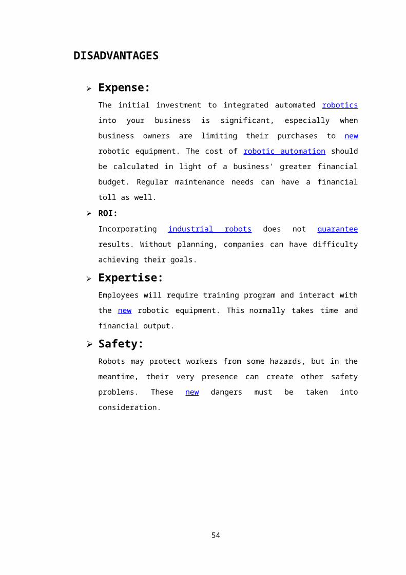
DISADVANTAGES
Expense:The initial investment to integrated automated robotics into your business is
significant, especially when business owners are limiting their purchases to new
robotic equipment. The cost of robotic automation should be calculated in light of a
business' greater financial budget. Regular maintenance needs can have a financial
toll as well.
ROI:
Incorporating industrial robots does not guarantee results. Without planning,
companies can have difficulty achieving their goals.
Expertise:Employees will require training program and interact with the new robotic equipment.
This normally takes time and financial output.
Safety:Robots may protect workers from some hazards, but in the meantime, their very
presence can create other safety problems. These new dangers must be taken into
consideration.
41

42

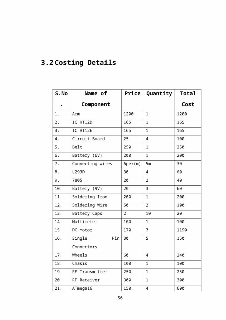
3.2 Costing Details
S.No. Name of Component Price Quantity Total Cost1. Arm 1200 1 1200
2. IC HT12D 165 1 165
3. IC HT12E 165 1 165
4. Circuit Board 25 4 100
5. Belt 250 1 250
6. Battery (6V) 200 1 200
7. Connecting wires 6per(m) 5m 30
8. L293D 30 4 60
9. 7805 20 2 40
10. Battery (9V) 20 3 60
11. Soldering Iron 200 1 200
12. Soldering Wire 50 2 100
13. Battery Caps 2 10 20
14. Multimeter 100 1 100
15. DC motor 170 7 1190
16. Single Pin Connectors 30 5 150
17. Wheels 60 4 240
18. Chasis 100 1 100
19. RF Transmitter 250 1 250
20. RF Receiver 300 1 300
21. ATmega16 controller 150 4 600
Fig 6.5 Table of costing details of all components of the Project
The total cost of the project hence was about Rs. 5640(approx.)
43

CHAPTER 4
4. SOFTWARE TOOLS
4.1 AVR studio:
AVR Studio is an Integrated Development Environment (IDE) for writing and debugging AVR applications in Windows 9x/ME/NT/2000/XP/VISTA environments. AVR Studio provides a project management tool, source file editor, simulator,assembler and front-end for C/C++, programming, emulation and on-chip debugging.
AVR Studio supports the complete range of ATMEL AVR tools and each release will always contain the latest updates for both the tools and support of new AVR devices.
AVR Studio 4 has a modular architecture which allows even more interaction with 3rd party software vendors. GUI plug-ins and other modules can be written and hooked to the system. Please contact us if you are interested in more information about this.
TRANSMITTER’S BLOCK :
#include<avr/io.h>
#include<util/delay.h>
void main()
{
DDRA=0XF0;
DDRC=0XFF;
DDRB=0XFF;
while(1)
{ PORTA=0X1F;
{_delay_ms(40);
if(PINA==0X1E)
{ PORTB=0X01;
PORTC=0X01;
_delay_ms(40);
}
44
else if(PINA==0X1D)
{ PORTB=0X02;
PORTC=0X02;
_delay_ms(40);
}
else if(PINA==0X1B)
{
PORTB=0X03;
PORTC=0X04;
_delay_ms(40);
}
else if(PINA==0X17)
{ PORTB=0X04;
PORTC=0X08;
_delay_ms(40);
}
}
PORTA=0X2F;
{
_delay_ms(40);
if(PINA==0X2E)
{ PORTB=0X05;
PORTC=0X01;
_delay_ms(40);
}
else if(PINA==0X2D)
{ PORTB=0X06;
PORTC=0X02;
_delay_ms(40);
}
else if(PINA==0X2B)
{ PORTB=0X07;
PORTC=0X04;
_delay_ms(40);
45

}
else if(PINA==0X27)
{ PORTB=0X08;
PORTC=0X08;
_delay_ms(40);
}
}
}
}
RECEIVER’S BLOCK :
#include<avr/io.h>#include<util/delay.h>
//adc_read(int);
void main()
{
DDRD=0xff;
DDRB=0Xf0;
DDRC=0xff;
int a=0;
while(1)
{ if(PINB==0X01)
{
PORTD=0X05;
PORTC=0x01;
_delay_ms(10);
}
if(PINB==0x02)
{
PORTD=0X06;
PORTC=0x02;
_delay_ms(10);
}
if(PINB==0x03)
{
PORTD=0X00;
46

PORTC=0x04;
_delay_ms(10);
}
if(PINB==0x04)
{
PORTD=0X0A;
PORTC=0x08;
_delay_ms(10);
}
if(PINB==0X05)
{
PORTD=0X10;
PORTC=0x01;
_delay_ms(10);
}
if(PINB==0x06)
{
PORTD=0X20;
PORTC=0x02;
_delay_ms(10);
}
if(PINB==0x07)
{
PORTD=0X40;
PORTC=0x04;
_delay_ms(10);
}
if(PINB==0x08)
{
PORTD=0X80;
PORTC=0x08;
_delay_ms(10);
}
}
}
4.2 SAFETY REQUIREMENTS
47
The various safety requirements which were considered while designing the robot are decided as follows:
1. The Robot should not be programmed such that it should damage the Battery while holding it in its gripper.
2. Correct holding position should be set as if it not set then while movement of the Robot it may drop the Lead Batteries which can arise a Hazardous situation in the industry.
3. The Robot should be interfaced properly with the sensors been placed near the Belt conveyor so as to know when the belt conveyor is to be stopped or to be started to move the batteries ahead.
4. Load carrying capacity should be maintained as it should be always more than the default load which is to be shifted.
CONCLUSION AND FUTURE SCOPE
CONCLUSION:
In this project we have studied and implemented a Pick and Place Robot using a
Microcontroller. The programming and interfacing of microcontroller has been
mastered during the implementation.
FUTURE SCOPE:
Smarter versions of pick and place robot are used to deliver mails within office
building and deliver medications in a hospital.
This technology has been suggested for running buses and other mass transit
systems and may end up as a part of autonomous cars navigating the freeway.
Used in heavy machinery industry
Used where high load and risky operation going on
Use in place of the crane
48

REFERENCES :
www.avrfreaks.com,Microcontrollers,Atmel
septiembre-2001. www.atmel.com
The 8051 Microcontroller and Embedded Systems Using Assembly and C
By Muhammad Ali Mazidi, Janice Gillispie Mazidi & Ro linD. McKinley
Atmel Corp. Makers of the AVR
microcontroller
www.atmel.com
www.electronic projects.com
www.howstuffworks.com
Electrikindia.
EMBEDDED SYSTEM BY RAJ KAMAL
49

APPENDIX A
Datasheet of IC L293D
50
51

APPENDIX BDatasheet of IC 7805
52

53
54
55
56