wireless networks & mobile computingalphace.ac.in/downloads/notes/cse/10cs831.pdf · wireless...
TRANSCRIPT

Wireless Networks & Mobile Computing 10CS831
LECTURE NOTES ON
WIRELESS NETWORKS
AND
MOBILE COMPUTING
Department of Computer Science and Engineering
Alpha College of Engineering,
#30/2, Hennur – Bagalur Road, Kannur Post,
Bangalore – 560 077

Wireless Networks & Mobile Computing 10CS831
Unit-1
Introduction to Mobile Computing
The rapidly expanding technology of cellular communication, wireless LANs,
and satellite services will make information accessible anywhere and at any time.
Regardless of size, most mobile computers will be equipped with a wireless connection to
the fixed part of the network, and, perhaps, to other mobile computers. The resulting
computing environment, which is often referred to as mobile or nomadic computing, no
longer requires users to maintain a fixed and universally known position in the
network and enables almost unrestricted mobility. Mobility and portability will create an
entire new class of applications and, possibly, new massive markets combining personal
computing and consumer electronics.
Mobile Computing is an umbrella term used to describe technologies that enable people
to access network services anyplace, anytime, and anywhere.
A communication device can exhibit any one of the following characteristics:
Fixed and wired: This configuration describes the typical desktop computer in an office.
Neither weight nor power consumption of the devices allow for mobile usage. The
devices use fixed networks for performance reasons.
Mobile and wired: MaŶLJ of todaLJs laptops fall iŶto this ĐategoƌLJ; useƌs carry the
laptop from one hotel to the next, reconnecting to the ĐoŵpaŶLJs network via the
telephone network and a modem.
Fixed and wireless: This mode is used for installing networks, e.g., in historical
buildings to avoid damage by installing wires, or at trade shows to ensure fast network
setup.
Mobile and wireless: This is the most interesting case. No cable restricts the user, who
can roam between different wireless networks.
APPLICATIONS OF MOBILE COMPUTING
In many fields of work, the ability to keep on the move is vital in order to utilise
time efficiently. The importance of Mobile Computers has been highlighted in many
fields of which a few are described below:
a. Vehicles: Music, news, road conditions, weather reports, and other broadcast information
are received via digital audio broadcasting (DAB) with 1.5 Mbit/s. For personal
communication, a universal mobile telecommunications system (UMTS) phone might be
available offering voice and data connectivity with 384 kbit/s. The current position of the
car is determined via the global positioning system (GPS). Cars driving in the same area
build a local ad-hoc network for the fast exchange of information in emergency situations
or to help each other keep a safe distance. In case of an accident, not only will the airbag

Wireless Networks & Mobile Computing 10CS831
be triggered, but the police and ambulance service will be informed via an emergency call
to a service provider. Buses, trucks, and trains are already transmitting maintenance and
logistic information to their home base, which helps to improve organization (fleet
management), and saves time and money.
b. Emergencies: An ambulance with a high-quality wireless connection to a hospital can
carry vital information about injured persons to the hospital from the scene of the
accident. All the necessary steps for this particular type of accident can be prepared and
specialists can be consulted for an early diagnosis. Wireless networks are the only means
of communication in the case of natural disasters such as hurricanes or earthquakes. In
the worst cases, only decentralized, wireless ad-hoc networks survive.
c. Business: Managers can use mobile computers say, critical presentations to major
customers. They can access the latest market share information. At a small recess, they
can revise the presentation to take advantage of this information. They can communicate
with the office about possible new offers and call meetings for discussing responds to the
new proposals. Therefore, mobile computers can leverage competitive advantages. A
travelling salesman today needs instant access to the company’s database: to ensure
that files on his or her laptop reflect the current situation, to enable the company to keep
track of all activities of their travelling employees, to keep databases consistent etc.
With wireless access, the laptop can be turned into a true mobile office, but efficient
and powerful synchronization mechanisms are needed to ensure data consistency.
d. Credit Card Verification: At Point of Sale (POS) terminals in shops and supermarkets,
when customers use credit cards for transactions, the intercommunication required
between the bank central computer and the POS terminal, in order to effect verification of
the card usage, can take place quickly and securely over cellular channels using a mobile
computer unit. This can speed up the transaction process and relieve congestion at the
POS terminals.
e. Replacement of Wired Networks: wireless networks can also be used to replace wired
networks, e.g., remote sensors, for tradeshows, or in historic buildings. Due to
economic reasons, it is often impossible to wire remote sensors for weather forecasts,
earthquake detection, or to provide environmental information. Wireless connections,
e.g., via satellite, can help in this situation. Other examples for wireless networks are
computers, sensors, or information displays in historical buildings, where excess cabling
may destroy valuable walls or floors.
f. Infotainment: wireless networks can provide up-to-date information at any appropriate
location. The travel guide might tell you something about the history of a building
(knowing via GPS, contact to a local base station, or triangulation where you are)
downloading information about a concert in the building at the same evening via a local
wireless network. Another growing field of wireless network applications lies in
entertainment and games to enable, e.g., ad-hoc gaming networks as soon as people

Wireless Networks & Mobile Computing 10CS831
meet to play together.
Limitations of Mobile Computing
Resource constraints: Battery
Interference: Radio transmission cannot be protected against interference using
shielding and result in higher loss rates for transmitted data or higher bit error rates
respectively
Bandwidth: Although they are continuously increasing, transmission rates are still
very low for wireless devices compared to desktop systems. Researchers look for
more efficient communication protocols with low overhead.
Dynamic changes in communication environment: variations in signal power within a
region, thus link delays and connection losses
Network Issues: discovery of the connection-service to destination and connection
stability
Interoperability issues: the varying protocol standards
Security constraints: Not only can portable devices be stolen more easily, but the
radio interface is also prone to the dangers of eavesdropping. Wireless access must
always include encryption, authentication, and other security mechanisms that must
be efficient and simple to use.
A simplified reference model
The figure shows the protocol stack implemented in the system according to the
reference model. End-systems, such as the PDA and computer in the example, need a full
protocol stack comprising the application layer, transport layer, network layer, data link
layer, and physical layer. Applications on the end-systems communicate with each other
using the lower layer services. Intermediate systems, such as the interworking unit, do not
necessarily need all of the layers.
A Simplified Reference Model

Wireless Networks & Mobile Computing 10CS831
Physical layer: This is the lowest layer in a communication system and is responsible for
the conversion of a stream of bits into signals that can be transmitted on the sender side. The
physical layer of the receiver then transforms the signals back into a bit stream. For wireless
communication, the physical layer is responsible for frequency selection, generation of the
carrier frequency, signal detection (although heavy interference may disturb the signal),
modulation of data onto a carrier frequency and (depending on the transmission scheme)
encryption.
Data link layer: The main tasks of this layer include accessing the medium, multiplexing
of different data streams, correction of transmission errors, and synchronization (i.e.,
detection of a data frame). Altogether, the data link layer is responsible for a reliable point-
to-point connection between two devices or a point-to-multipoint connection between one
sender and several receivers.
Network layer: This third layer is responsible for routing packets through a network or
establishing a connection between two entities over many other intermediate systems.
Important functions are addressing, routing, device location, and handover between different
networks.
Transport layer: This layer is used in the reference model to establish an end-to-end
connection
Application layer: Finally, the applications (complemented by additional layers that can
support applications) are situated on top of all transmission oriented layers. Functions are
service location, support for multimedia applications, adaptive applications that can handle
the large variations in transmission characteristics, and wireless access to the world-wide
web using a portable device.
GSM : Mobile services, System architecture, Radio interface, Protocols, Localization
and calling, Handover, Security, and New data services.
GSM Services
GSM is the most successful digital mobile telecommunication system in the world today. It is
used by over 800 million people in more than 190 countries. GSM permits the integration of
different voice and data services and the interworking with existing networks. Services make
a network interesting for customers. GSM has defined three different categories of services:
bearer, tele and supplementary services.
Bearer services: GSM specifies different mechanisms for data transmission, the original
GSM allowing for data rates of up to 9600 bit/s for non-voice services. Bearer services
permit transparent and non-transparent, synchronous or asynchronous data transmission.
Transparent bearer services only use the functions of the physical layer (layer 1) to
transmit data. Data transmissionhas aconstant delayandthroughput ifnotransmissionerrors
occur. Transmission quality can be improved with the use of forward error correction
(FEC), which codes redundancy into the data stream and helps to reconstruct the original
data in case of transmission errors. Transparent bearer services do not try to recover lost
data in case of, for example, shadowing or interruptions due to handover. Non-transparent
Wireless Networks & Mobile Computing 10CS831
bearer services use protocols of layers two and three to implement error correction and
flow control. These services use the transparent bearer services, adding a radio link
protocol (RLP). This protocol comprises mechanisms of high-level data link control
(HDLC), and special selective-reject mechanisms to trigger retransmission of erroneous data.
Using transparent and non-transparent services, GSM specifies several bearer services for
interworking with PSTN, ISDN, and packet switched public data networks (PSPDN) like
X.25, which is available worldwide. Data transmission can be full-duplex, synchronous with
data rates of 1.2, 2.4, 4.8, and 9.6 kbit/s or full-duplex, asynchronous from 300 to 9,600 bit/s.
Tele services: GSM mainly focuses on voice-oriented tele services. These comprise
encrypted voice transmission, message services, and basic data communication with
terminals as known from the PSTN or ISDN (e.g., fax). The primary goal of GSM was the
provision of high-quality digital voice transmission. Special codecs (coder/decoder) are used
for voice transmission, while other codecs are used for the transmission of analog data for
communication with traditional computer modems used in, e.g., fax machines. Another
service offered by GSM is the emergency number (eg 911, 999). This service is
mandatory for all providers and free of charge. This connection also has the highest
priority, possibly pre-empting other connections, and will automatically be set up with the
closest emergency center. A useful service for very simple message transfer is the short
message service (SMS), which offers transmission of messages of up to 160 characters.
Sending and receiving of SMS is possible during data or voice transmission. It can be used
for “serious” applications such as displaying road conditions, e-mail headers or stock
quotes, but it can also transfer logos, ring tones, horoscopes and love letters.
The successor of SMS, the enhanced message service (EMS), offers a larger message size,
formatted text, and the transmission of animated pictures, small images and ring tones in a
standardized way. But with MMS, EMS was hardly used. MMS offers the transmission
of larger pictures (GIF, JPG, WBMP), short video clips etc. and comes with mobile
phones that integrate small cameras. Another non-voice tele service is group 3 fax, which
is available worldwide. In this service, fax data is transmitted as digital data over the analog
telephone network according to the ITU-T standards T.4 and T.30 using modems.
Supplementary services: In addition to tele and bearer services, GSM providers can
supplementary services. these services offer various enhancements for the standard
telephony service, and may vary from provider to provider. Typical services are user
identification, call redirection, or forwarding of ongoing calls, barring of
incoming/outgoing calls, Advice of Charge (AoC) etc. Standard ISDN features such as
closed user groups and multiparty communication may be available.
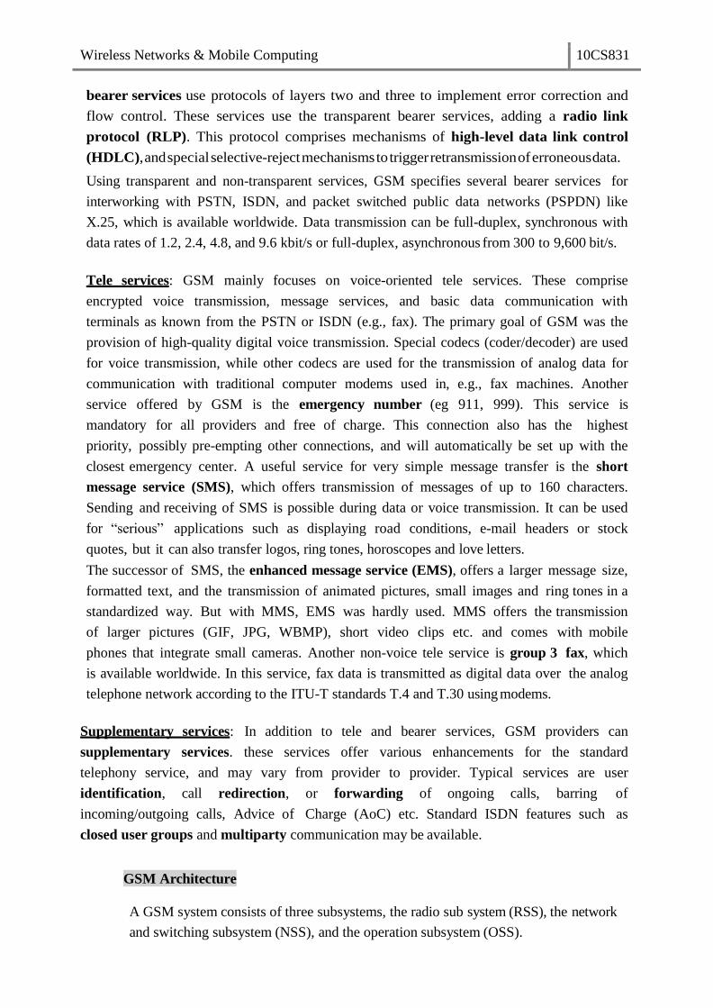
GSM Architecture
A GSM system consists of three subsystems, the radio sub system (RSS), the network
and switching subsystem (NSS), and the operation subsystem (OSS).

Wireless Networks & Mobile Computing 10CS831
Functional Architecture of a GSM System
Network Switching Subsystem: The NSS is responsible for performing
callprocessing and subscriber related functions. The switching system includes the
following functional units:
Home location register (HLR): It is a database used for storage and management
of subscriptions. HLR stores permanent data about subscribers, including a
subscribers service profile, location information and activity status. When an
individual buys a subscription from the PCS provider, he or she is registered in the
HLR of that operator.
Visitor location register (VLR): It is a database that contains temporary information
about subscribers that is needed by the MSC in order to service visiting
subscribers. VLR is always integrated with the MSC. When a MS roams into a
new MSC area, the VLR connected to that MSC will request data about the mobile
station from the HLR. Later if the mobile station needs to make a call, VLR will be
having all the information needed for call setup.
Authentication center (AUC): A unit called the AUC provides authentication and
encryption parameters that verify the users identity and ensure the confidentiality
of each call.
Equipment identity register (EIR): It is a database that contains information about
the identity of mobile equipment that prevents calls from stolen, unauthorized or
defective mobile stations.
Mobile switching center (MSC): The MSC performs the telephony switching
functions of the system. It controls calls to and from other telephone and data
systems.
Radio Subsystem (RSS): the radio subsystem (RSS) comprises all radio specific
entities, i.e., the mobile stations (MS) and the base station subsystem (BSS). The
figure shows the connection between the RSS and the NSS via the A interface (solid
lines) and the connection to the OSS via the O interface (dashed lines).

Wireless Networks & Mobile Computing 10CS831
Base station subsystem (BSS): A GSM network comprises many BSSs, each
controlled by a base station controller (BSC). The BSS performs all functions
necessary to maintain radio connections to an MS, coding/decoding of voice, and
rate adaptation to/from the wireless network part. Besides a BSC, the BSS contains
several BTSs.
Base station controllers (BSC): The BSC provides all the control functions and
physical links between the MSC and BTS. It is a high capacity switch that provides
functions such as handover, cell configuration data, and control of radio frequency
(RF) power levels in BTS. A number of BSC’s are served by and MSC.
Base transceiver station (BTS): The BTS handles the radio interface to the
mobile station. A BTS can form a radio cell or, using sectorized antennas, several
and is connected to MS via the Um interface, and to the BSC via the Abis
interface. The Um interface contains all the mechanisms necessary for wireless
transmission (TDMA, FDMA etc.)The BTS is the radio equipment (transceivers and
antennas) needed to service each cell in the network. A group of BTS’s are controlled
by an BSC.
Operation and Support system: The operations and maintenance center (OMC) is
connected to all equipment in the switching system and to the BSC. Implementation of
OMC is called operation and support system (OSS). The OSS is the functional entity
from which the network operator monitors and controls the system. The purpose of
OSS is to offer the customer cost-effective support for centralized, regional and local
operational and maintenance activities that are required for a GSM network. OSS
provides a network overview and allows engineers to monitor, diagnose and
troubleshoot every aspect of the GSM network.
The mobile station (MS) consists of the mobile equipment (the terminal) and a smart
card called the Subscriber Identity Module (SIM). The SIM provides personal mobility,
so that the user can have access to subscribed services irrespective of a specific
terminal. By inserting the SIM card into another GSM terminal, the user is able to
receive calls at that terminal, make calls from that terminal, and receive other subscribed
services.
The mobile equipment is uniquely identified by the International Mobile Equipment
Identity (IMEI). The SIM card contains the International Mobile Subscriber Identity
(IMSI) used to identify the subscriber to the system, a secret key for authentication,
and other information. The IMEI and the IMSI are independent, thereby allowing
personal mobility. The SIM card may be protected against unauthorized use by a
password or personal identity number.
Radio Interface
The most interesting interface in a GSM system is Um, the radio interface, as it
comprises various multiplexing and media access mechanisms. GSM implements
SDMA using cells with BTS and assigns an MS to a BTS.
Wireless Networks & Mobile Computing 10CS831
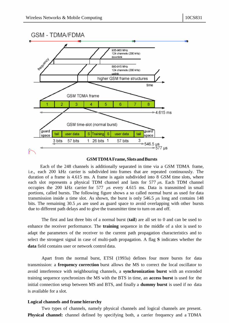
GSMTDMAFrame, Slotsand Bursts
Each of the 248 channels is additionally separated in time via a GSM TDMA frame,
i.e., each 200 kHz carrier is subdivided into frames that are repeated continuously. The
duration of a frame is 4.615 ms. A frame is again subdivided into 8 GSM time slots, where
each slot represents a physical TDM channel and lasts for 577 μs. Each TDM channel
occupies the 200 kHz carrier for 577 μs every 4.615 ms. Data is transmitted in small
portions, called bursts. The following figure shows a so called normal burst as used for data
transmission inside a time slot. As shown, the burst is only 546.5 μs long and contains 148
bits. The remaining 30.5 μs are used as guard space to avoid overlapping with other bursts
due to different path delays and to give the transmitter time to turn on and off.
The first and last three bits of a normal burst (tail) are all set to 0 and can be used to
enhance the receiver performance. The training sequence in the middle of a slot is used to
adapt the parameters of the receiver to the current path propagation characteristics and to
select the strongest signal in case of multi-path propagation. A flag S indicates whether the
data field contains user or network control data.
Apart from the normal burst, ETSI (1993a) defines four more bursts for data
transmission: a frequency correction burst allows the MS to correct the local oscillator to
avoid interference with neighbouring channels, a synchronization burst with an extended
training sequence synchronizes the MS with the BTS in time, an access burst is used for the
initial connection setup between MS and BTS, and finally a dummy burst is used if no data
is available for a slot.
Logical channels and frame hierarchy
Two types of channels, namely physical channels and logical channels are present.
Physical channel: channel defined by specifying both, a carrier frequency and a TDMA

Wireless Networks & Mobile Computing 10CS831
timeslot number. Logic channel: logical channels are multiplexed into the physical channels.
Each logic channel performs a specific task. Consequently the data of a logical channel is
transmitted in the corresponding timeslots of the physical channel. During this process,
logical channels can occupy a part of the physical channel or even the entire channel.
Each of the frequency carriers is divided into frames of 8 timeslots of approximately
is 4.615ms (577 s x 8 = 4.615 ms). The bits per timeslot and frame duration yield a gross
bit rate of about 271kbps per TDMA frame.
TDMA frames are grouped into two types of multiframes:
26-frame multiframe (4.615ms x 26 = 120 ms) comprising of 26 TDMA frames.
This multiframe is used to carry traffic channels and their associated control
channels.
51-frame multiframe (4.615ms x 51 235.4 ms) comprising 51 TDMA frames.
This multiframe is exclusively used for control channels.
The multiframe structure is further multiplexed into a single superframe of duration of
6.12sec. This means a superframe consists of
51 multiframes of 26 frames.
26 multiframes of 51 frames.
The last multiplexing level of the frame hierarchy, consisting of 2048 superframes (2715648
TDMA frames), is a hyperframe. This long time period is needed to support the GSM data
encryption mechanisms. The frame hierarchy is shown below:
GSMFrameHierarchy
s)
Wireless Networks & Mobile Computing 10CS831
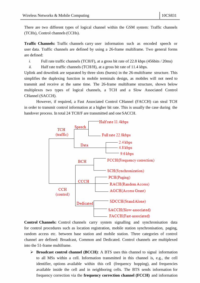
There are two different types of logical channel within the GSM system: Traffic channels
(TCHs), Control channels (CCHs).
Traffic Channels: Traffic channels carry user information such as encoded speech or
user data. Traffic channels are defined by using a 26-frame multiframe. Two general forms
are defined:
i. Full rate traffic channels (TCH/F), at a gross bit rate of 22.8 kbps (456bits / 20ms)
ii. Half rate traffic channels (TCH/H), at a gross bit rate of 11.4 kbps.
Uplink and downlink are separated by three slots (bursts) in the 26-multiframe structure. This
simplifies the duplexing function in mobile terminals design, as mobiles will not need to
transmit and receive at the same time. The 26-frame multiframe structure, shown below
multiplexes two types of logical channels, a TCH and a Slow Associated Control
CHannel (SACCH).
However, if required, a Fast Associated Control CHannel (FACCH) can steal TCH
in order to transmit control information at a higher bit rate. This is usually the case during the
handover process. In total 24 TCH/F are transmitted and one SACCH.
Control Channels: Control channels carry system signalling and synchronisation data
for control procedures such as location registration, mobile station synchronisation, paging,
random access etc. between base station and mobile station. Three categories of control
channel are defined: Broadcast, Common and Dedicated. Control channels are multiplexed
into the 51-frame multiframe.
Broadcast control channel (BCCH): A BTS uses this channel to signal information
to all MSs within a cell. Information transmitted in this channel is, e.g., the cell
identifier, options available within this cell (frequency hopping), and frequencies
available inside the cell and in neighboring cells. The BTS sends information for
frequency correction via the frequency correction channel (FCCH) and information

Wireless Networks & Mobile Computing 10CS831
about time synchronization via the synchronization channel (SCH), where both
channels are subchannels of the BCCH.
Common control channel (CCCH): All information regarding connection setup
between MS and BS is exchanged via the CCCH. For calls toward an MS, the BTS
uses the paging channel (PCH) for paging the appropriate MS. If an MS wants to set
up a call, it uses the random access channel (RACH) to send data to the BTS.
The RACH implements multiple access (all MSs within a cell may access this
channel) using slotted Aloha. This is where a collision may occur with other MSs
in a GSM system. The BTS uses the access grant channel (AGCH) to signal an MS
that it can use a TCH or SDCCH for further connection setup.
Dedicated control channel (DCCH): While the previous channels have all been
unidirectional, the following channels are bidirectional. As long as an MS has not
established a TCH with the BTS, it uses the stand-alone dedicated control
channel (SDCCH) with a low data rate (782 bit/s) for signaling. This can comprise
authentication, registration or other data needed for setting up a TCH. Each TCH and
SDCCH has a slow associated dedicated control channel (SACCH) associated with
it, which is used to exchange system information, such as the channel quality and
signal power level. Finally, if more signaling information needs to be transmitted and
a TCH already exists, GSM uses a fast associated dedicated control channel
(FACCH). The FACCH uses the time slots which are otherwise used by the TCH.
This is necessary in the case of handovers where BTS and MS have to exchange
larger amounts of data in less time.
GSM Protocols
The signalling protocol in GSM is structured into three general layers depending on the
interface, as shown below. Layer 1 is the physical layer that handles all radio-specific
functions. This includes the creation of bursts according to the five different formats,
multiplexing of bursts into a TDMA frame, synchronization with the BTS, detection of idle
channels, and measurement of the channel quality on the downlink. The physical layer at
Um uses GMSK for digital modulation and performs encryption/decryption of data, i.e.,
encryption is not performed end-to-end, but only between MS and BSS over the air interface.
Protocol architecture for Signaling

Wireless Networks & Mobile Computing 10CS831
The main tasks of the physical layer comprise channel coding and error
detection/correction, which is directly combined with the coding mechanisms. Channel
coding makes extensive use of different forward error correction (FEC) schemes.
Signaling between entities in a GSM network requires higher layers. For this purpose, the
LAPDm protocol has been defined at the Um interface for layer two. LAPDm has been
derived from link access procedure for the D-channel (LAPD) in ISDN systems, which is a
version of HDLC. LAPDm is a lightweight LAPD because it does not need synchronization
flags or checksumming for error detection. LAPDm offers reliable data transfer over
connections, re- sequencing of data frames, and flow control.
The network layer in GSM, layer three, comprises several sublayers. The lowest
sublayer is the radio resource management (RR). Only a part of this layer, RR’, is
implemented in the BTS, the remainder is situated in the BSC. The functions of RR’
are supported by the BSC via the BTS management (BTSM). The main tasks of RR are setup,
maintenance, and release of radio channels. Mobility management (MM) contains functions
for registration, authentication, identification, location updating, and the provision of a
temporary mobile subscriber identity (TMSI).
Finally, the call management (CM) layer contains three entities: call control (CC),
short message service (SMS), and supplementary service (SS). SMS allows for message
transfer using the control channels SDCCH and SACCH, while SS offers the services like
user identification, call redirection, or forwarding of ongoing calls. CC provides a point-
to-point connection between two terminals and is used by higher layers for call
establishment, call clearing and change of call parameters. This layer also provides
functions to send in-band tones, called dual tone multiple frequency (DTMF), over the
GSM network. These tones are used, e.g., for the remote control of answering machines or
the entry of PINs in electronic banking and are, also used for dialing in traditional analog
telephone systems.
Additional protocols are used at the Abis and A interfaces. Data transmission at the
physical layer typically uses pulse code modulation (PCM) systems. LAPD is used for layer
two at Abis, BTSM for BTS management. Signaling system No. 7 (SS7) is used for
signaling between an MSC and a BSC. This protocol also transfers all management
information between MSCs, HLR, VLRs, AuC, EIR, and OMC. An MSC can also control
a BSS via a BSS application part (BSSAP).
Localization and Calling
The fundamental feature of the GSM system is the automatic, worldwide localization of users
for which, the system performs periodic location updates. The HLR always contains
information about the current location and the VLR currently responsible for the MS informs
the HLR about the location changes. Changing VLRs with uninterrupted availability is called
roaming. Roaming can take place within a network of one provider, between two providers
in a country and also between different providers in different countries.
To locate and address an MS, several numbers are needed:

Wireless Networks & Mobile Computing 10CS831
Mobile station international ISDN number (MSISDN):- The only important
number for a user of GSM is the phone number. This number consists of the
country code (CC), the national destination code (NDC) and the subscriber number
(SN).
International mobile subscriber identity (IMSI): GSM uses the IMSI for internal
unique identification of a subscriber. IMSI consists of a mobile country code (MCC),
the mobile network code (MNC), and finally the mobile subscriber identification
number (MSIN).
Temporary mobile subscriber identity (TMSI): To hide the IMSI, which would
give away the exact identity of the user signalling over the air interface, GSM uses
the 4 byte TMSI for local subscriber identification.
Mobile station roaming number (MSRN): Another temporary address that hides the
identity and location of a subscriber is MSRN. The VLR generates this address on
request from the MSC, and the address is also stored in the HLR. MSRN contains the
current visitor country code (VCC), the visitor national destination code (VNDC),
the identification of the current MSC together with the subscriber number. The MSRN
helps the HLR to find a subscriber for an incoming call.
For a mobile terminated call (MTC), the following figure shows the different steps that take
place:
Mobile Terminated Call (MTC)
step 1: User dials the phone number of a GSM subscriber.
step 2: The fixed network (PSTN) identifies the number belongs to a user in GSM network
and forwards the call setup to the Gateway MSC (GMSC).
step 3: The GMSC identifies the HLR for the subscriber and signals the call setup to HLR
step 4: The HLR checks for number existence and its subscribed services and requests
an MSRN from the current VLR.

Wireless Networks & Mobile Computing 10CS831
step 5: VLR sends the MSRN to HLR
step 6: Upon receiving MSRN, the HLR determines the MSC responsible for MS and forwards
the information to the GMSC
step 7: The GMSC can now forward the call setup request to the MSC indicated
step 8: The MSC requests the VLR for the current status of the MS
step 9: VLR sends the requested information
step 10: If MS is available, the MSC initiates paging in all cells it is responsible for.
step 11: The BTSs of all BSSs transmit the paging signal to the MS
step 12: Step 13: If MS answers, VLR performs security checks
step 15: Till step 17: Then the VLR signals to the MSC to setup a connection to the MS
For a mobile originated call (MOC), the following steps take place:
step 1: The MS transmits a request for a new connection
step 2: The BSS forwards this request to the MSC
step 3: Step 4: The MSC then checks if this user is allowed to set up a call with the requested
and checks the availability of resources through the GSM network and into the PSTN.
If all resources are available, the MSC sets up a connection between the MS and the
fixed network.
In addition to the steps mentioned above, other messages are exchanged between an MS and
BTS during connection setup (in either direction).
Message flow for MTC and MOC

Wireless Networks & Mobile Computing 10CS831
Handover
Cellular systems require handover procedures, as single cells do not cover the whole service
area. However, a handover should not cause a cut-off, also called call drop. GSM aims at
maximum handover duration of 60 ms. There are two basic reasons for a handover:
1. The mobile station moves out of the range of a BTS, decreasing the received signal
level increasing the error rate thereby diminishing the quality of the radio link.
2. Handover may be due to load balancing, when an MSC/BSC decides the traffic is too
high in one cell and shifts some MS to other cells with a lower load.
The four possible handover scenarios of GSM are shown below:
Intra-cell handover: Within a cell, narrow-band interference could make
transmission at a certain frequency impossible. The BSC could then decide to
change the carrier frequency (scenario 1).
Inter-cell, intra-BSC handover: This is a typical handover scenario. The mobile
station moves from one cell to another, but stays within the control of the same
BSC. The BSC then performs a handover, assigns a new radio channel in the new
cell and releases the old one (scenario 2).
Inter-BSC, intra-MSC handover: As a BSC only controls a limited number of
cells; GSM also has to perform handovers between cells controlled by different
BSCs. This handover then has to be controlled by the MSC (scenario 3).
Inter MSC handover: A handover could be required between two cells belonging to
different MSCs. Now both MSCs perform the handover together (scenario 4).
To provide all the necessary information for a handover due to a weak link, MS and BTS
both perform periodic measurements of the downlink and uplink quality respectively.
Measurement reports are sent by the MS about every half-second and contain the quality of
the current link used for transmission as well as the quality of certain channels in
neighboring cells (the BCCHs).

Wireless Networks & Mobile Computing 10CS831
Handover decision depending on receive level
Intra-MSChandover
More sophisticated handover mechanisms are needed for seamless handovers between
different systems.
Security
GSM offers several security services using confidential information stored in the AuC and in
the individual SIM. The SIM stores personal, secret data and is protected with a PIN against
unauthorized use. Three algorithms have been specified to provide security services in GSM.
Algorithm A3 is used for authentication, A5 for encryption, and A8 for the generation of
a cipher key. The various security services offered by GSM are:
Wireless Networks & Mobile Computing 10CS831
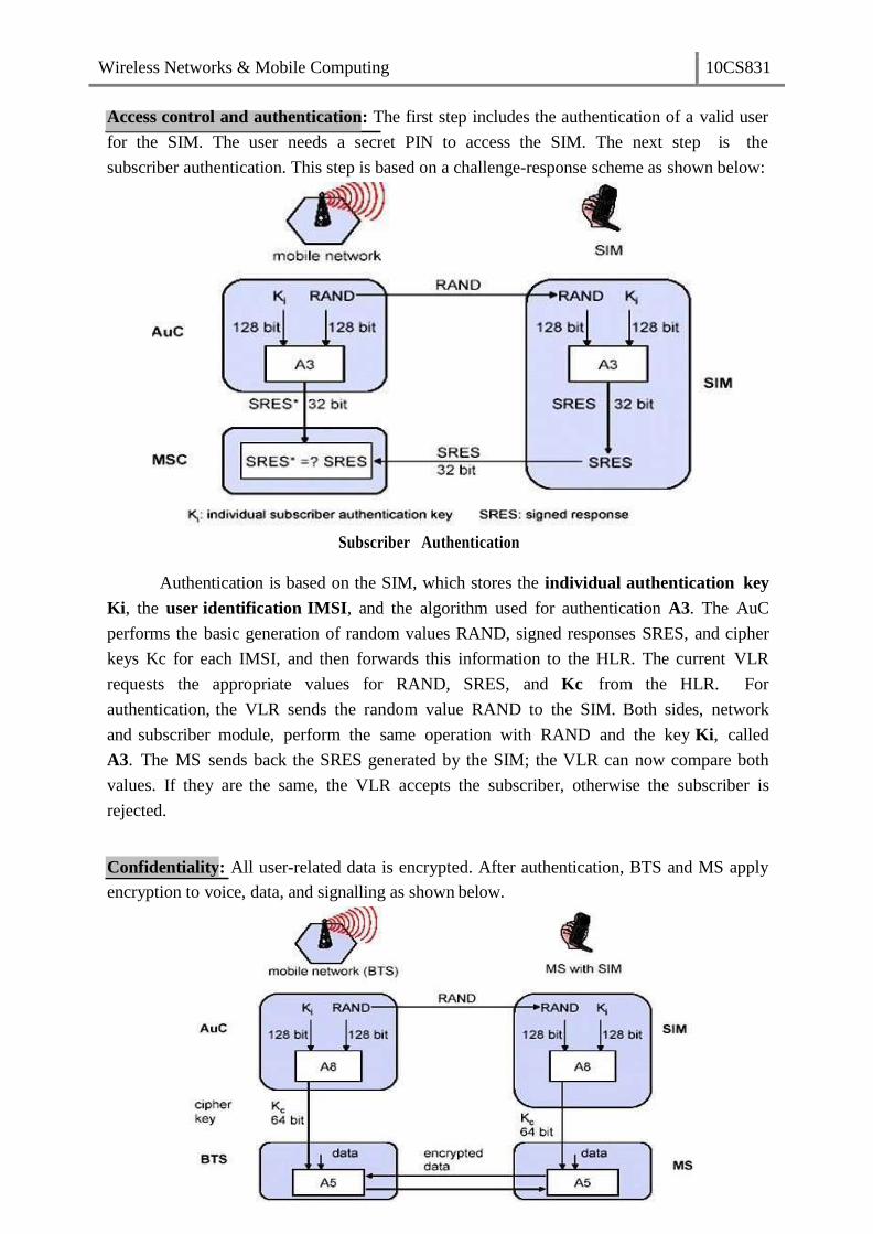
Access control and authentication: The first step includes the authentication of a valid user
for the SIM. The user needs a secret PIN to access the SIM. The next step is the
subscriber authentication. This step is based on a challenge-response scheme as shown below:
Subscriber Authentication
Authentication is based on the SIM, which stores the individual authentication key
Ki, the user identification IMSI, and the algorithm used for authentication A3. The AuC
performs the basic generation of random values RAND, signed responses SRES, and cipher
keys Kc for each IMSI, and then forwards this information to the HLR. The current VLR
requests the appropriate values for RAND, SRES, and Kc from the HLR. For
authentication, the VLR sends the random value RAND to the SIM. Both sides, network
and subscriber module, perform the same operation with RAND and the key Ki, called
A3. The MS sends back the SRES generated by the SIM; the VLR can now compare both
values. If they are the same, the VLR accepts the subscriber, otherwise the subscriber is
rejected.
Confidentiality: All user-related data is encrypted. After authentication, BTS and MS apply
encryption to voice, data, and signalling as shown below.

Wireless Networks & Mobile Computing 10CS831
Anonymity:
To ensure privacy, all messages containing user-related information are encrypted in GSM
over the air interface. After authentication, MS and BSS can start using encryption by
applying the cipher key Kc, which is generated using the individual key Ki and a random
value by applying the algorithm A8. Note that the SIM in the MS and the network both
calculate the same Kc based on the random value RAND. The key Kc itself is not
transmitted over the air interface. MS and BTS can now encrypt and decrypt data using the
algorithm A5 and the cipher key Kc.
To provide user anonymity, all data is encrypted before transmission, and
user identifiers are not used over the air. Instead, GSM transmits a temporary identifier
(TMSI), which is newly assigned by the VLR after each location update. Additionally, the
VLR can change the TMSI at any time.
New Data Services
To enhance the data transmission capabilities of GSM, two basic approaches are possible. As
the basic GSM is based on connection-oriented traffic channels, e.g., with 9.6 kbit/s each,
several channels could be combined to increase bandwidth. This system is called
HSCSD high speed circuit switched data. A more progressive step is the introduction
of packet- oriented traffic in GSM, i.e., shifting the paradigm from connections/telephone
thinking to packets/internet thinking. The system is called GPRS general packet radio
service.
HSCD: A straightforward improvement of GSM’s data transmission capabilities is high
speed circuit switched data (HSCSD) in which higher data rates are achieved by bundling
several TCHs. An MS requests one or more TCHs from the GSM network, i.e., it allocates
several TDMA slots within a TDMA frame. This allocation can be asymmetrical, i.e. more
slots can be allocated on the downlink than on the uplink, which fits the typical user
behaviour of downloading more data compared to uploading. A major disadvantage of
HSCD is that it still uses the connection-oriented mechanisms of GSM, which is not efficient
for computer data traffic.
GPRS: The next step toward more flexible and powerful data transmission avoids the
problems of HSCSD by being fully packet-oriented. The general packet radio service
(GPRS) provides packet mode transfer for applications that exhibit traffic patterns such as
frequent transmission of small volumes (e.g., typical web requests) or infrequent
transmissions of small or medium volumes (e.g., typical web responses) according to the
requirement specification. For the new GPRS radio channels, the GSM system can allocate
between one and eight time slots within a TDMA frame. Time slots are not allocated in a
fixed, pre-determined manner but on demand. All time slots can be shared by the active
users; up- and downlink are allocated separately. Allocation of the slots is based on current
load and operator preferences. The GPRS concept is independent of channel characteristics
and of the type of channel (traditional GSM traffic or control channel), and does not limit
the maximum data rate (only the GSM transport system limits the rate). All GPRS services
can be used in parallel to conventional services. GPRS includes several security services
such as authentication, access control, user identity confidentiality, and user information
Wireless Networks & Mobile Computing 10CS831
confidentiality.
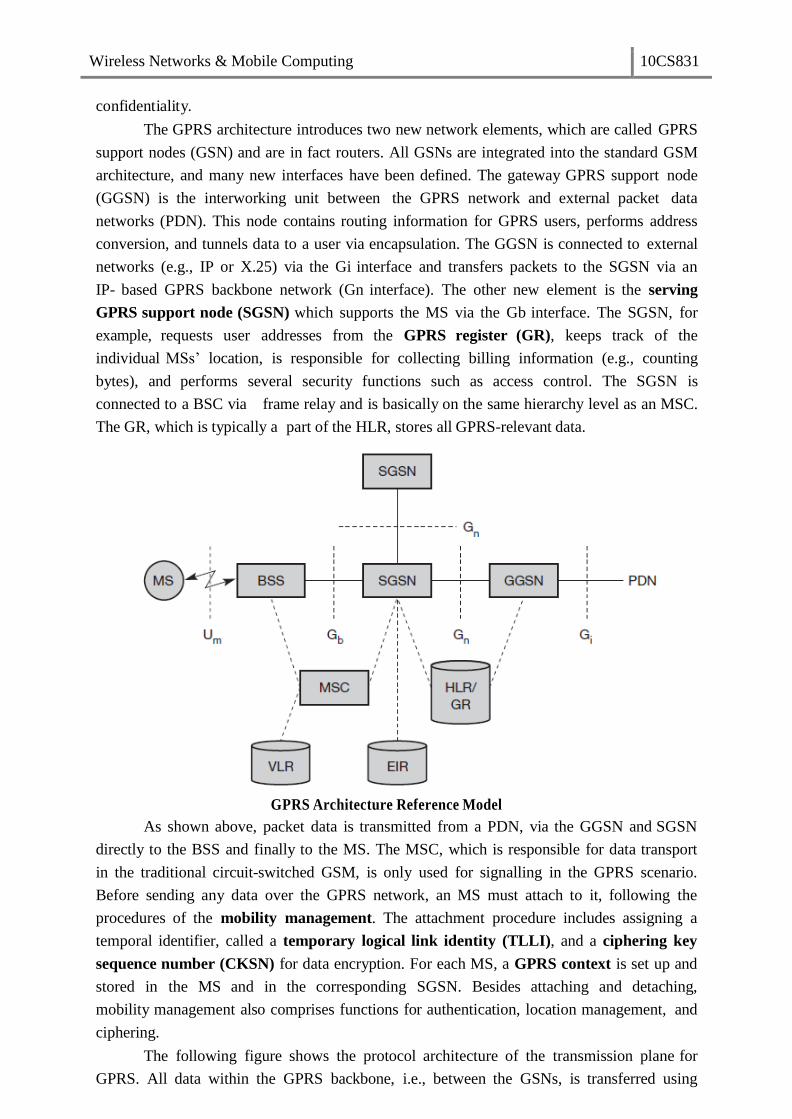
The GPRS architecture introduces two new network elements, which are called GPRS
support nodes (GSN) and are in fact routers. All GSNs are integrated into the standard GSM
architecture, and many new interfaces have been defined. The gateway GPRS support node
(GGSN) is the interworking unit between the GPRS network and external packet data
networks (PDN). This node contains routing information for GPRS users, performs address
conversion, and tunnels data to a user via encapsulation. The GGSN is connected to external
networks (e.g., IP or X.25) via the Gi interface and transfers packets to the SGSN via an
IP- based GPRS backbone network (Gn interface). The other new element is the serving
GPRS support node (SGSN) which supports the MS via the Gb interface. The SGSN, for
example, requests user addresses from the GPRS register (GR), keeps track of the
individual MSs’ location, is responsible for collecting billing information (e.g., counting
bytes), and performs several security functions such as access control. The SGSN is
connected to a BSC via frame relay and is basically on the same hierarchy level as an MSC.
The GR, which is typically a part of the HLR, stores all GPRS-relevant data.
GPRS Architecture Reference Model
As shown above, packet data is transmitted from a PDN, via the GGSN and SGSN
directly to the BSS and finally to the MS. The MSC, which is responsible for data transport
in the traditional circuit-switched GSM, is only used for signalling in the GPRS scenario.
Before sending any data over the GPRS network, an MS must attach to it, following the
procedures of the mobility management. The attachment procedure includes assigning a
temporal identifier, called a temporary logical link identity (TLLI), and a ciphering key
sequence number (CKSN) for data encryption. For each MS, a GPRS context is set up and
stored in the MS and in the corresponding SGSN. Besides attaching and detaching,
mobility management also comprises functions for authentication, location management, and
ciphering.
The following figure shows the protocol architecture of the transmission plane for
GPRS. All data within the GPRS backbone, i.e., between the GSNs, is transferred using

Wireless Networks & Mobile Computing 10CS831
the GPRS tunnelling protocol (GTP). GTP can use two different transport protocols, either
the reliable TCP (needed for reliable transfer of X.25 packets) or the non-reliable UDP
(used for IP packets). The network protocol for the GPRS backbone is IP (using any lower
layers). To adapt to the different characteristics of the underlying networks, the subnetwork
dependent convergence protocol (SNDCP) is used between an SGSN and the MS. On top
of SNDCP and GTP, user packet data is tunneled from the MS to the GGSN and vice versa.
To achieve a high reliability of packet transfer between SGSN and MS, a special LLC is
used, which comprises ARQ and FEC mechanisms for PTP (and later PTM) services.
GPRS transmission plane protocol reference model
A base station subsystem GPRS protocol (BSSGP) is used to convey routing and
QoS- related information between the BSS and SGSN. BSSGP does not perform error
correction and works on top of a frame relay (FR) network. Finally, radio link dependent
protocols are needed to transfer data over the Um interface. The radio link protocol (RLC)
provides a reliable link, while the MAC controls access with signalling procedures for the
radio channel and the mapping of LLC frames onto the GSM physical channels. The radio
interface at Um needed for GPRS does not require fundamental changes compared to
standard GSM.

Wireless Networks & Mobile Computing 10CS831
Unit:2
.
The Media Access Control (MAC) data communication protocol sub-layer, also known as
the Medium Access Control, is a sublayer of the Data Link Layer specified in the seven-
layer OSI model (layer 2). The hardware that implements the MAC is referred to as a
Medium Access Controller. The MAC sub-layer acts as an interface between the Logical
Link Control (LLC) sublayer and the network's physical layer. The MAC layer emulates a
full-duplex logical communication channel in a multi-point network. This channel may
provide unicast, multicast or broadcast communication service.
LLC and MAC sublayers
Motivation for a specialized MAC
One of the most commonly used MAC schemes for wired networks is
carrier sense multiple access with collision detection (CSMA/CD). In this scheme, a
sender senses the medium (a wire or coaxial cable) to see if it is free. If the medium
is busy, the sender waits until it is free. If the medium is free, the sender starts
transmitting data and continues to listen into the medium. If the sender detects a
collision while sending, it stops at once and sends a jamming signal. But this
scheme doest work well with wireless networks. The problems are:
Signal strength decreases proportional to the square of the distance
The sender would apply CS and CD, but the collisions happen at the receiver
It might be a case that a sender cannot “hear” the collision, i.e., CD does not work
Furthermore, CS might not work, if for e.g., a terminal is “hidden”
Hidden and Exposed Terminal
Consider the scenario with three mobile phones as shown below. The transmission
range of A reaches B, but not C (the detection range does not reach C either). The
transmission range of C reaches B, but not A. Finally, the transmission range of B
reaches A and C, i.e., A cannot detect C and vice versa.
Wireless Networks & Mobile Computing 10CS831
Hidden terminals
A sends to B, C cannot hear A
C wants to send to B, C senses a “free” medium (CS fails) and starts transmitting
Collision at B occurs, A cannot detect this collision (CD fails) and continues with its
transmission to B
A is “hidden” from C and vice versa
Exposed terminals
B sends to A, C wants to send to another terminal (not A or B) outside the range
C senses the carrier and detects that the carrier is busy.
C postpones its transmission until it detects the medium as being idle again
but A is outside radio range of C, waiting is not necessary
C is “exposed” to B
Hidden terminals cause collisions, where as Exposed terminals causes unnecessary delay.
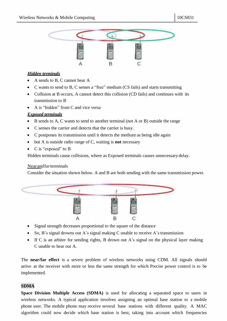
Near and far terminals
Consider the situation shown below. A and B are both sending with the same transmission power.
Signal strength decreases proportional to the square of the distance
So, B’s signal drowns out A’s signal making C unable to receive A’s transmission
If C is an arbiter for sending rights, B drown out A’s signal on the physical layer making
C unable to hear out A.
The near/far effect is a severe problem of wireless networks using CDM. All signals should
arrive at the receiver with more or less the same strength for which Precise power control is to be
implemented.
SDMA
Space Division Multiple Access (SDMA) is used for allocating a separated space to users in
wireless networks. A typical application involves assigning an optimal base station to a mobile
phone user. The mobile phone may receive several base stations with different quality. A MAC
algorithm could now decide which base station is best, taking into account which frequencies

Wireless Networks & Mobile Computing 10CS831
(FDM), time slots (TDM) or code (CDM) are still available. The basis for the SDMA algorithm
is formed by cells and sectorized antennas which constitute the infrastructure implementing space
division multiplexing (SDM). SDM has the unique advantage of not requiring any multiplexing
equipment. It is usually combined with other multiplexing techniques to better utilize the individual
physical channels.
FDMA
Frequency division multiplexing (FDM) describes schemes to subdivide the frequency
dimension into several non-overlapping frequency bands.
Frequency Division Multiple Access is a method employed to permit several users to
transmit simultaneously on one satellite transponder by assigning a specific frequency within the
channel to each user. Each conversation gets its own, unique, radio channel. The channels are
relatively narrow, usually 30 KHz or less and are defined as either transmit or receive
channels. A full duplex conversation requires a transmit & receive channel pair. FDM is often used
for simultaneous access to the medium by base station and mobile station in cellular networks
establishing a duplex channel. A scheme called frequency division duplexing (FDD) in which
the two directions, mobile station to base station and vice versa are now separated using different
frequencies.
FDM for multiple access and duplex
The two frequencies are also known as uplink, i.e., from mobile station to base station or
from ground control to satellite, and as downlink, i.e., from base station to mobile station or from

Wireless Networks & Mobile Computing 10CS831
satellite to ground control. The basic frequency allocation scheme for GSM is fixed and
regulated by national authorities. All uplinks use the band between 890.2 and 915 MHz, all
downlinks use 935.2 to 960 MHz. According to FDMA, the base station, shown on the right side,
allocates a certain frequency for up- and downlink to establish a duplex channel with a mobile
phone. Up- and downlink have a fixed relation. If the uplink frequency is fu = 890 MHz + n·
0.2 MHz, the downlink frequency is fd = fu + 45 MHz,
., fd = 935 MHz + n· 0.2 MHz for a certain channel n. The base station selects the
channel. Each channel (uplink and downlink) has a bandwidth of 200 kHz.
This scheme also has disadvantages. While radio stations broadcast 24 hours a day,
mobile communication typically takes place for only a few minutes at a time. Assigning a
separate frequency for each possible communication scenario would be a tremendous waste of
(scarce) frequency resources. Additionally, the fixed assignment of a frequency to a sender
makes the scheme very inflexible and limits the number of senders.
TDMA
A more flexible multiplexing scheme for typical mobile communications is time division
multiplexing (TDM). Compared to FDMA, time division multiple access (TDMA) offers a much
more flexible scheme, which comprises all technologies that allocate certain time slots for
communication. Now synchronization between sender and receiver has to be achieved in the
time domain. Again this can be done by using a fixed pattern similar to FDMA techniques, i.e.,
allocating a certain time slot for a channel, or by using a dynamic allocation scheme.
Listening to different frequencies at the same time is quite difficult, but listening to many
channels separated in time at the same frequency is simple. Fixed schemes do not need
identification, but are not as flexible considering varying bandwidth requirements.
Fixed TDM
The simplest algorithm for using TDM is allocating time slots for channels in a fixed pattern.
This results in a fixed bandwidth and is the typical solution for wireless phone systems. MAC is
quite simple, as the only crucial factor is accessing the reserved time slot at the right moment. If
this synchronization is assured, each mobile station knows its turn and no interference will
happen. The fixed pattern can be assigned by the base station, where competition between
different mobile stations that want to access the medium is solved.
Wireless Networks & Mobile Computing 10CS831
The above figure shows how these fixed TDM patterns are used to implement multiple access
and a duplex channel between a base station and mobile station. Assigning different slots for
uplink and downlink using the same frequency is called time division duplex (TDD). As shown
in the figure, the base station uses one out of 12 slots for the downlink, whereas the mobile
station uses one out of 12 different slots for the uplink. Uplink and downlink are separated in time.
Up to 12 different mobile stations can use the same frequency without interference using this
scheme. Each connection is allotted its own up- and downlink pair. This general scheme still
wastes a lot of bandwidth. It is too static, too inflexible for data communication. In this case,
connectionless, demand-oriented TDMA schemes can be used
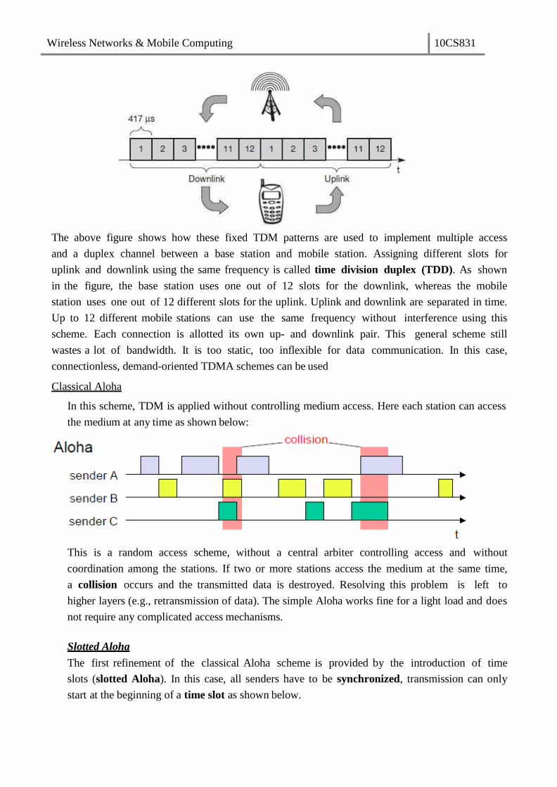
Classical Aloha
In this scheme, TDM is applied without controlling medium access. Here each station can access
the medium at any time as shown below:
This is a random access scheme, without a central arbiter controlling access and without
coordination among the stations. If two or more stations access the medium at the same time,
a collision occurs and the transmitted data is destroyed. Resolving this problem is left to
higher layers (e.g., retransmission of data). The simple Aloha works fine for a light load and does
not require any complicated access mechanisms.
Slotted Aloha
The first refinement of the classical Aloha scheme is provided by the introduction of time
slots (slotted Aloha). In this case, all senders have to be synchronized, transmission can only
start at the beginning of a time slot as shown below.
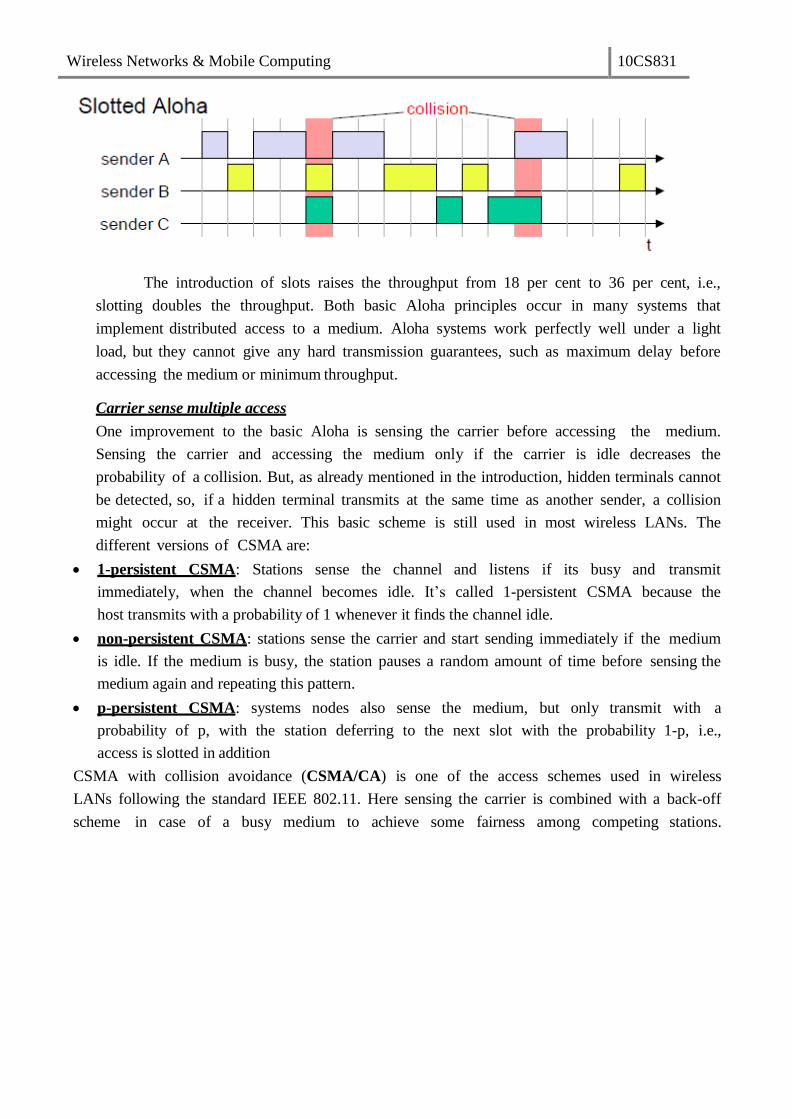
Wireless Networks & Mobile Computing 10CS831
The introduction of slots raises the throughput from 18 per cent to 36 per cent, i.e.,
slotting doubles the throughput. Both basic Aloha principles occur in many systems that
implement distributed access to a medium. Aloha systems work perfectly well under a light
load, but they cannot give any hard transmission guarantees, such as maximum delay before
accessing the medium or minimum throughput.
Carrier sense multiple access
One improvement to the basic Aloha is sensing the carrier before accessing the medium.
Sensing the carrier and accessing the medium only if the carrier is idle decreases the
probability of a collision. But, as already mentioned in the introduction, hidden terminals cannot
be detected, so, if a hidden terminal transmits at the same time as another sender, a collision
might occur at the receiver. This basic scheme is still used in most wireless LANs. The
different versions of CSMA are:
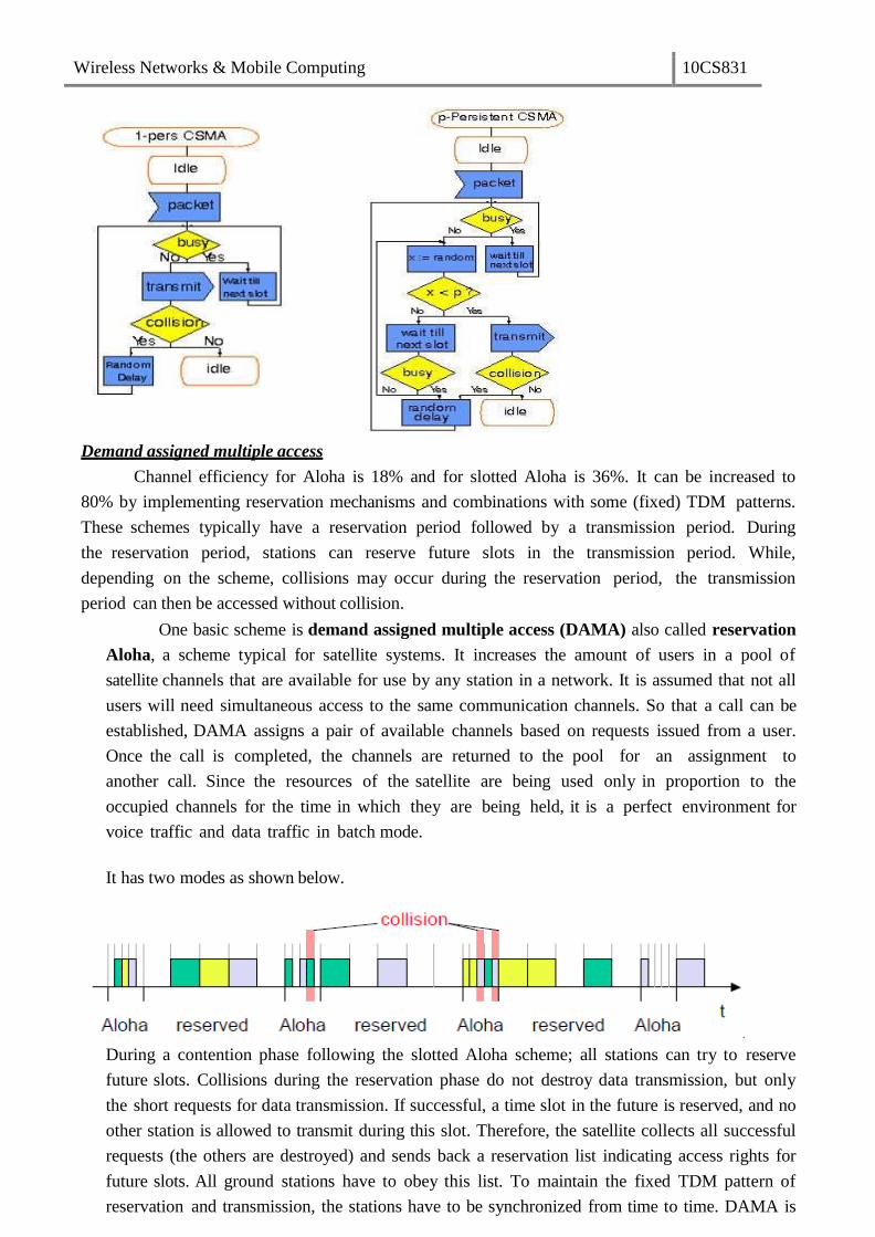
1-persistent CSMA: Stations sense the channel and listens if its busy and transmit
immediately, when the channel becomes idle. It’s called 1-persistent CSMA because the
host transmits with a probability of 1 whenever it finds the channel idle.
non-persistent CSMA: stations sense the carrier and start sending immediately if the medium
is idle. If the medium is busy, the station pauses a random amount of time before sensing the
medium again and repeating this pattern.
p-persistent CSMA: systems nodes also sense the medium, but only transmit with a
probability of p, with the station deferring to the next slot with the probability 1-p, i.e.,
access is slotted in addition
CSMA with collision avoidance (CSMA/CA) is one of the access schemes used in wireless
LANs following the standard IEEE 802.11. Here sensing the carrier is combined with a back-off
scheme in case of a busy medium to achieve some fairness among competing stations.
Wireless Networks & Mobile Computing 10CS831
Demand assigned multiple access
Channel efficiency for Aloha is 18% and for slotted Aloha is 36%. It can be increased to
80% by implementing reservation mechanisms and combinations with some (fixed) TDM patterns.
These schemes typically have a reservation period followed by a transmission period. During
the reservation period, stations can reserve future slots in the transmission period. While,
depending on the scheme, collisions may occur during the reservation period, the transmission
period can then be accessed without collision.
One basic scheme is demand assigned multiple access (DAMA) also called reservation
Aloha, a scheme typical for satellite systems. It increases the amount of users in a pool of
satellite channels that are available for use by any station in a network. It is assumed that not all
users will need simultaneous access to the same communication channels. So that a call can be
established, DAMA assigns a pair of available channels based on requests issued from a user.
Once the call is completed, the channels are returned to the pool for an assignment to
another call. Since the resources of the satellite are being used only in proportion to the
occupied channels for the time in which they are being held, it is a perfect environment for
voice traffic and data traffic in batch mode.
It has two modes as shown below.
During a contention phase following the slotted Aloha scheme; all stations can try to reserve
future slots. Collisions during the reservation phase do not destroy data transmission, but only
the short requests for data transmission. If successful, a time slot in the future is reserved, and no
other station is allowed to transmit during this slot. Therefore, the satellite collects all successful
requests (the others are destroyed) and sends back a reservation list indicating access rights for
future slots. All ground stations have to obey this list. To maintain the fixed TDM pattern of
reservation and transmission, the stations have to be synchronized from time to time. DAMA is

Wireless Networks & Mobile Computing 10CS831
an explicit reservation scheme. Each transmission slot has to be reserved explicitly.
PRMA packet reservation multiple access
It is a kind of implicit reservation scheme where, slots can be reserved implicitly. A
certain number of slots form a frame. The frame is repeated in time i.e., a fixed TDM pattern is
applied. A base station, which could be a satellite, now broadcasts the status of each slot to all
mobile stations. All stations receiving this vector will then know which slot is occupied and
which slot is currently free.
The base station broadcasts the reservation status ‘ACDABA-F’ to all stations, here A
to F. This means that slots one to six and eight are occupied, but slot seven is free in the
following transmission. All stations wishing to transmit can now compete for this free slot in
Aloha fashion. The already occupied slots are not touched. In the example shown, more than one
station wants to access this slot, so a collision occurs. The base station returns the reservation
status ‘ACDABA-F’, indicating that the reservation of slot seven failed (still indicated as free)
and that nothing has changed for the other slots. Again, stations can compete for this slot.
Additionally, station D has stopped sending in slot three and station F in slot eight. This is
noticed by the base station after the second frame. Before the third frame starts, the base station
indicates that slots three and eight are now idle. Station F has succeeded in reserving slot seven as
also indicated by the base station.
As soon as a station has succeeded with a reservation, all future slots are implicitly
reserved for this station. This ensures transmission with a guaranteed data rate. The slotted aloha
scheme is used for idle slots only; data transmission is not destroyed by collision.
Reservation TDMA
In a fixed TDM scheme N mini-slots followed by N·k data-slots form a frame that is repeated.
Each station is allotted its own mini-slot and can use it to reserve up to k data-slots.
Wireless Networks & Mobile Computing 10CS831
This guarantees each station a certain bandwidth and a fixed delay. Other stations can now
send data in unused data-slots as shown. Using these free slots can be based on a simple
round-robin scheme or can be uncoordinated using an Aloha scheme. This scheme allows for
the combination of, e.g., isochronous traffic with fixed bitrates and best-effort traffic without any
guarantees.
Multiple access with collision avoidance
Multiple access with collision avoidance (MACA) presents a simple scheme that solves the
hidden terminal problem, does not need a base station, and is still a random access Aloha
scheme – but with dynamic reservation. Consider the hidden terminal problem scenario.
A starts sending to B, C does not receive this transmission. C also wants to send something to B
and senses the medium. The medium appears to be free, the carrier sense fails. C also starts
sending causing a collision at B. But A cannot detect this collision at B and continues with its
transmission. A is hidden for C and vice versa.
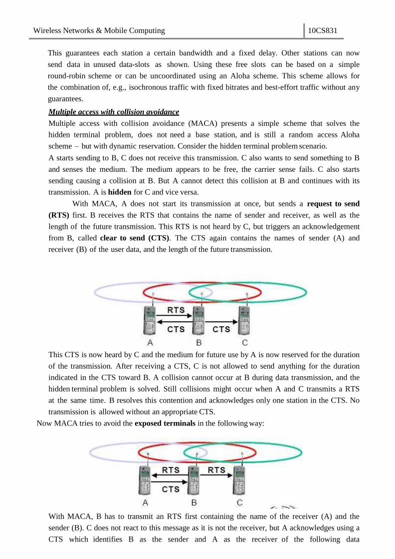
With MACA, A does not start its transmission at once, but sends a request to send
(RTS) first. B receives the RTS that contains the name of sender and receiver, as well as the
length of the future transmission. This RTS is not heard by C, but triggers an acknowledgement
from B, called clear to send (CTS). The CTS again contains the names of sender (A) and
receiver (B) of the user data, and the length of the future transmission.
This CTS is now heard by C and the medium for future use by A is now reserved for the duration
of the transmission. After receiving a CTS, C is not allowed to send anything for the duration
indicated in the CTS toward B. A collision cannot occur at B during data transmission, and the
hidden terminal problem is solved. Still collisions might occur when A and C transmits a RTS
at the same time. B resolves this contention and acknowledges only one station in the CTS. No
transmission is allowed without an appropriate CTS.
Now MACA tries to avoid the exposed terminals in the following way:
With MACA, B has to transmit an RTS first containing the name of the receiver (A) and the
sender (B). C does not react to this message as it is not the receiver, but A acknowledges using a
CTS which identifies B as the sender and A as the receiver of the following data

Wireless Networks & Mobile Computing 10CS831
transmission. C does not receive this CTS and concludes that A is outside the detection range.
C can start its transmission assuming it will not cause a collision at A. The problem with
exposed terminals is solved without fixed access patterns or a base station.
Polling
Polling schemes are used when one station wants to be heard by others. Polling is a strictly
centralized scheme with one master station and several slave stations. The master can poll
the slaves according to many schemes: round robin (only efficient if traffic patterns are similar
over all stations), randomly, according to reservations (the classroom example with polite
students) etc. The master could also establish a list of stations wishing to transmit during a
contention phase. After this phase, the station polls each station on the list.
Example: Randomly Addressed Polling
base station signals readiness to all mobile terminals
terminals ready to send transmit random number without collision using CDMA or FDMA
the base station chooses one address for polling from list of all random numbers (collision if two
terminals choose the same address)
the base station acknowledges correct packets and continues polling the next terminal
this cycle starts again after polling all terminals of the list
Inhibit sense multiple access
This scheme, which is used for the packet data transmission service Cellular Digital Packet Data
(CDPD) in the AMPS mobile phone system, is also known as digital sense multiple access
(DSMA). Here, the base station only signals a busy medium via a busy tone (called
BUSY/IDLE indicator) on the downlink.
After the busy tone stops, accessing the uplink is not coordinated any further. The base
station acknowledges successful transmissions; a mobile station detects a collision only via
the missing positive acknowledgement. In case of collisions, additional back-off and
retransmission mechanisms are implemented.
CDMA
Code division multiple access systems apply codes with certain characteristics to the
transmission to separate different users in code space and to enable access to a shared medium
without interference.
Wireless Networks & Mobile Computing 10CS831
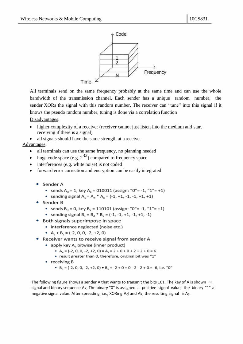
All terminals send on the same frequency probably at the same time and can use the whole
bandwidth of the transmission channel. Each sender has a unique random number, the
sender XORs the signal with this random number. The receiver can “tune” into this signal if it
knows the pseudo random number, tuning is done via a correlation function
Disadvantages:
higher complexity of a receiver (receiver cannot just listen into the medium and start
receiving if there is a signal)
all signals should have the same strength at a receiver
Advantages:
all terminals can use the same frequency, no planning needed
huge code space (e.g. 232
) compared to frequency space
interferences (e.g. white noise) is not coded
forward error correction and encryption can be easily integrated
The following figure shows a sender A that wants to transmit the bits 101. The key of A is shown as
signal and binary sequence Ak. The binary “0” is assigned a positive signal value, the binary “1” a
negative signal value. After spreading, i.e., XORing Ad and Ak, the resulting signal is As.
Wireless Networks & Mobile Computing 10CS831
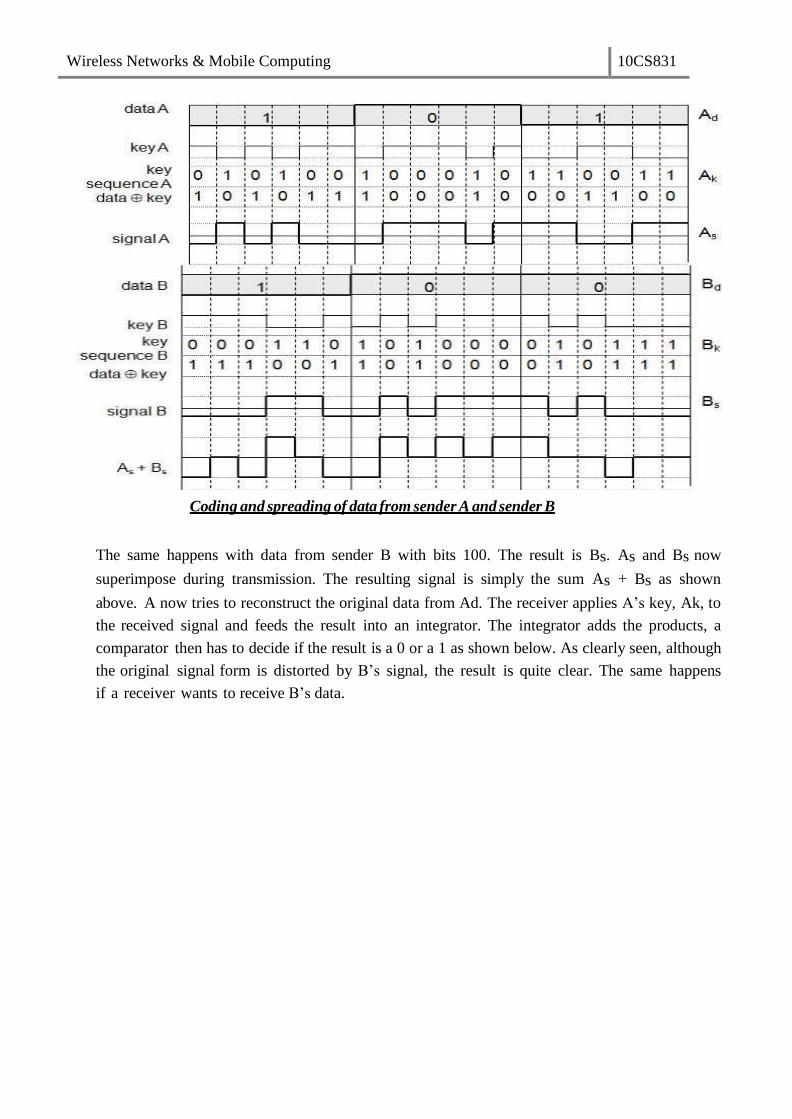
Coding and spreading of data from sender A and sender B
The same happens with data from sender B with bits 100. The result is Bs. As and Bs now
superimpose during transmission. The resulting signal is simply the sum As + Bs as shown
above. A now tries to reconstruct the original data from Ad. The receiver applies A’s key, Ak, to
the received signal and feeds the result into an integrator. The integrator adds the products, a
comparator then has to decide if the result is a 0 or a 1 as shown below. As clearly seen, although
the original signal form is distorted by B’s signal, the result is quite clear. The same happens
if a receiver wants to receive B’s data.

Wireless Networks & Mobile Computing 10CS831
Reconstruction of A’s data
Soft handover or soft handoff refers to a feature used by the CDMA and WCDMA standards,
where a cell phone is simultaneously connected to two or more cells (or cell sectors) during a
call. If the sectors are from the same physical cell site (a sectorised site), it is referred to as
softer handoff. This technique is a form of mobile-assisted handover, for IS-95/CDMA2000
CDMA cell phones continuously make power measurements of a list of neighboring cell sites,
and determine whether or not to request or end soft handover with the cell sectors on the list.
Soft handoff is different from the traditional hard-handoff process. With hard handoff,
a definite decision is made on whether to hand off or not. The handoff is initiated and
executed without the user attempting to have simultaneous traffic channel communications
with the two base stations. With soft handoff, a conditional decision is made on whether to hand
off. Depending on the changes in pilot signal strength from the two or more base stations
involved, a hard decision will eventually be made to communicate with only one. This
normally happens after it is evident that the signal from one base station is considerably
stronger than those from the others. In the interim period, the user has simultaneous traffic
channel communication with all candidate base stations. It is desirable to implement soft
handoff in power-controlled CDMA systems because implementing hard handoff is potentially
difficult in such systems.

Wireless Networks & Mobile Computing 10CS831
Spread Aloha multiple access (SAMA)
CDMA senders and receivers are not really simple devices. Communicating with n devices
requires programming of the receiver to be able to decode n different codes. Aloha was a very
simple scheme, but could only provide a relatively low bandwidth due to collisions. SAMA
uses spread spectrum with only one single code (chipping sequence) for spreading for all
senders accessing according to aloha.
In SAMA, each sender uses the same spreading code, for ex 110101 as shown below.
Sender A and B access the medium at the same time in their narrowband spectrum, so that the
three bits shown causes collisions. The same data could also be sent with higher power for
shorter periods as show.
The main problem in using this approach is finding good chipping sequences. The maximum
throughput is about 18 per cent, which is very similar to Aloha, but the approach benefits from
the advantages of spread spectrum techniques: robustness against narrowband interference and
simple coexistence with other systems in the same frequency
band.
Wireless Networks & Mobile Computing 10CS831
UNIT-3
MOBILE NETWORK LAYER
Need for Mobile IP
The IP addresses are designed to work with stationary hosts because part of the
address defines the network to which the host is attached. A host cannot change its IP
address without terminating on-going sessions and restarting them after it acquires a new
address. Other link layer mobility solutions exist but are not sufficient enough for the global
Internet.
Mobility is the ability of a node to change its point-of-attachment while maintaining all
existing communications and using the same IP address.
Nomadicity allows a node to move but it must terminate all existing communications
and then can initiate new connections with a new address.
Mobile IP is a network layer solution for homogenous and
heterogeneous mobility on the global Internet which is
scalable, robust, secure and which allows nodes to maintain
all ongoing communications while moving.
Design Goals: Mobile IP was developed as a means for transparently dealing with problems
of mobile users. Mobile IP was designed to make the size and the frequency of
required routing updates as small as possible. It was designed to make it simple to
implement mobile node software. It was designed to avoid solutions that require mobile
nodes to use multiple addresses.
Requirements: There are several requirements for Mobile IP to make it as a standard. Some
of them are:
1. Compatibility: The whole architecture of internet is very huge and a new standard
cannot introduce changes to the applications or network protocols already in use.
Mobile IP is to be integrated into the existing operating systems. Also, for routers also
it may be possible to enhance its capabilities to support mobility instead of changing
the routers which is highly impossible. Mobile IP must not require special media or
MAC/LLC protocols, so it must use the same interfaces and mechanisms to access
the lower layers as IP does. Finally, end-systems enhanced with a mobile IP
implementation should still be able to communicate with fixed systems without
mobile IP.
2. Transparency: Mobility remains invisible for many higher layer protocols and
applications. Higher layers continue to work even if the mobile computer has
changed its point of attachment to the network and even notice a lower bandwidth and
some interruption in the service. As many of today’s applications have not been
designed to use in mobile environments, the effects of mobility will be higher delay
and lower bandwidth.
Wireless Networks & Mobile Computing 10CS831
3. Scalability and efficiency: The efficiency of the network should not be affected even
if a new mechanism is introduced into the internet. Enhancing IP for mobility must
not generate many new messages flooding the whole network. Special care is
necessary to be taken considering the lower bandwidth of wireless links. Many mobile
systems have a wireless link to an attachment point. Therefore, only some additional
packets must be necessary between a mobile system and a node in the network. It
is indispensable for a mobile IP to be scalable over a large number of participants
in the whole internet, throughout the world.
4. Security: Mobility possesses many security problems. A minimum requirement is the
authentication of all messages related to the management of mobile IP. It must be
sure for the IP layer if it forwards a packet to a mobile host that this host really is the
receiver of the packet. The IP layer can only guarantee that the IP address of the
receiver is correct. There is no way to prevent faked IP addresses and other attacks.
The goal of a mobile IP can be summarized as: ‘supporting end-system mobility while
maintaining scalability, efficiency, and compatibility in all respects with existing applications
and Internet protocols’.
Entities and terminology
The following defines several entities and terms needed to understand mobile IP as defined in
RFC 3344.
Mobile Node (MN): A mobile node is an end-system or router that can change its
point of attachment to the internet using mobile IP. The MN keeps its IP
address and can continuously communicate with any other system in the internet
as long as link-layer connectivity is given. Examples are laptop, mobile phone,
router on an aircraft etc.
Correspondent node (CN): At least one partner is needed for communication. In
the following the CN represents this partner for the MN. The CN can be a fixed or
mobile node.
Home network: The home network is the subnet the MN belongs to with respect
to its IP address. No mobile IP support is needed within the home network.
Foreign network: The foreign network is the current subnet the MN visits and
which is not the home network.
Foreign agent (FA): The FA can provide several services to the MN during its visit to
the foreign network. The FA can have the COA, acting as tunnel endpoint and
forwarding packets to the MN. The FA can be the default router for the MN. FAs
can also provide security services because they belong to the foreign network as
opposed to the MN which is only visiting. FA is implemented on a router for the
subnet the MN attaches to.
Care-of address (COA): The COA defines the current location of the MN from
an IP point of view. All IP packets sent to the MN are delivered to the COA, not
directly to the IP address of the MN. Packet delivery toward the MN is done using

Wireless Networks & Mobile Computing 10CS831
a tunnel, i.e., the COA marks the tunnel endpoint, i.e., the address where packets
exit the tunnel. There are two different possibilities for the location of the COA:
Foreign agent COA: The COA could be located at the FA, i.e., the COA is an
IP address of the FA. The FA is the tunnel end-point and forwards packets to the
MN. Many MN using the FA can share this COA as common COA.
Co-located COA: The COA is co-located if the MN temporarily acquired an
additional IP address which acts as COA. This address is now topologically correct,
and the tunnel endpoint is at the MN. Co-located addresses can be acquired using
services such as DHCP.
1. Home agent (HA): The HA provides several services for the MN and is located in
the home network. The tunnel for packets toward the MN starts at the HA. The HA
can be implemented on a router that is responsible for the home network. This is
obviously the best position, because without optimizations to mobile IP, all packets
for the MN have to go through the router anyway.
2. One disadvantage of this solution is the double crossing of the router by the packet if
the MN is in a foreign network. A packet for the MN comes in via the router; the
HA sends it through the tunnel which again crosses the router.
3. Finally, a home network is not necessary at all. The HA could be again on the ƌouteƌ
but this time only acting as a manager for MNs belonging to a virtual home network.
All MNs are always in a foreign network with this solution.
A CN is connected via a router to the internet, as are the home network and the foreign
network. The HA is implemented on the router connecting the home network with the
internet, an FA is implemented on the router to the foreign network. The MN is currently in
the foreign network. The tunnel for packets toward the MN starts at the HA and ends at the
FA, for the FA has the COA in the above example.
IP packet delivery
Consider the above example in which a correspondent node (CN) wants to send an IP packet
to the MN. One of the requirements of mobile IP was to support hiding the mobility of the
MN. CN does not need to know anything about the MNs current location and sends the
packet as usual to the IP address of MN as shown below.

Wireless Networks & Mobile Computing 10CS831
CN sends an IP packet with MN as a destination address and CN as a source address.
The internet, not having information on the current location of MN, routes the packet to the
router responsible for the home network of MN. This is done using the standard routing
mechanisms of the internet. The HA now intercepts the packet, knowing that MN is currently
not in its home network. The packet is not forwarded into the subnet as usual, but
encapsulated and tunnelled to the COA.
A new header is put in front of the old IP header showing the COA as new
destination and HA as source of the encapsulated packet (step 2). The foreign agent now
decapsulates the packet, i.e., removes the additional header, and forwards the original packet
with CN as source and MN as destination to the MN (step 3). Again, for the MN mobility
is not visible. It receives the packet with the same sender and receiver address as it would
have done in the home network.

Wireless Networks & Mobile Computing 10CS831
Sending packets from the mobile node (MN) to the CN is comparatively simple. The MN
sends the packet as usual with its own fixed IP address as source and CNs address as
destination (step 4). The router with the FA acts as default router and forwards the packet in
the same way as it would do for any other node in the foreign network. As long as CN is a
fixed node the remainder is in the fixed internet as usual. If CN were also a mobile node
residing in a foreign network, the same mechanisms as described in steps 1 through 3 would
apply now in the other direction.
Working of Mobile IP:- Mobile IP has two addresses for a mobile host: one home address and one care- of
address. The home address is permanent; the care-of address changes as the mobile host moves from one
network to another. To make the change of address transparent to the rest of the Internet requires a home
agent and a foreign agent. The specific function of an agent is performed in the application layer. When
the mobile host and the foreign agent are the same, the care-of address is called a co-located care-of
address. To communicate with a remote host, a mobile host goes through three phases: agent discovery,
registration, and data transfer.
Agent Discovery
A mobile node has to find a foreign agent when it moves away from its home network. To
solve this problem, mobile IP describes two methods: agent advertisement and agent
solicitation.
Agent advertisement
For this method, foreign agents and home agents advertise their presence periodically using
special agent advertisement messages, which are broadcast into the subnet. Mobile IP does
not use a new packet type for agent advertisement; it uses the router advertisement packet of
ICMP, and appends an agent advertisement message. The agent advertisement packet
according to RFC 1256 with the extension for mobility is shown below:
Wireless Networks & Mobile Computing 10CS831
The TTL field of the IP packet is set to 1 for all advertisements to avoid forwarding
them. The type is set to 9, the code can be 0, if the agent also routes traffic from non-
mobile nodes, or 16, if it does not route anything other than mobile traffic. The number of
addresses advertised with this packet is in #addresses while the addresses themselves
follow as shown. Lifetime denotes the length of time this advertisement is valid.
Preference levels for each address help a node to choose the router that is the most eager
one to get a new node.
The extension for mobility has the following fields defined: type is set to 16, length
depends on the number of COAs provided with the message and equals 6 + 4*(number of
addresses). The sequence number shows the total number of advertisements sent since
initialization by the agent. By the registration lifetime the agent can specify the maximum
lifetime in seconds a node can request during registration. The following bits specify the
characteristics of an agent in detail.
The R bit (registration) shows, if a registration with this agent is required even when
using a colocated COA at the MN. If the agent is currently too busy to accept new
registrations it can set the B bit. The following two bits denote if the agent offers services as a
home agent (H) or foreign agent (F) on the link where the advertisement has been sent. Bits
M and G specify the method of encapsulation used for the tunnel. While IP-in-IP
encapsulation is the mandatory standard, M can specify minimal encapsulation and G
generic routing encapsulation. In the first version of mobile IP (RFC 2002) the V bit specified
the use of header compression according to RFC 1144. Now the field r at the same bit
position is set to zero and must be ignored. The new field T indicates that reverse tunneling
is supported by the FA. The following fields contain the COAs advertised. A foreign agent
setting the F bit must advertise at least one COA. A mobile node in a subnet can now receive
agent advertisements from either its home agent or a foreign agent. This is one way for the
MN to discover its location.
Agent Solicitation
If no agent advertisements are present or the inter-arrival time is too high, and an MN has
not received a COA by other means, the mobile node must send agent solicitations. Care
must be taken to ensure that these solicitation messages do not flood the network, but
basically an MN can search for an FA endlessly sending out solicitation messages. If a node
does not receive an answer to its solicitations it must decrease the rate of solicitations
exponentially to avoid flooding the network until it reaches a maximum interval between
solicitations (typically one minute). Discovering a new agent can be done anytime, not just if
the MN is not connected to one.
After these steps of advertisements or solicitations the MN can now receive a COA,
either one for an FA or a co-located COA.
Agent Registration
Having received a COA, the MN has to register with the HA. The main purpose of the
registration is to inform the HA of the current location for correct forwarding of packets.
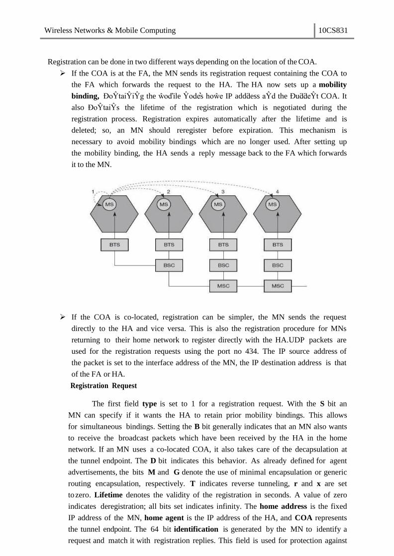
Wireless Networks & Mobile Computing 10CS831
Registration can be done in two different ways depending on the location of the COA.
If the COA is at the FA, the MN sends its registration request containing the COA to
the FA which forwards the request to the HA. The HA now sets up a mobility
binding, ĐoŶtaiŶiŶg the ŵoďile Ŷodes hoŵe IP addƌess aŶd the ĐuƌƌeŶt COA. It
also ĐoŶtaiŶs the lifetime of the registration which is negotiated during the
registration process. Registration expires automatically after the lifetime and is
deleted; so, an MN should reregister before expiration. This mechanism is
necessary to avoid mobility bindings which are no longer used. After setting up
the mobility binding, the HA sends a reply message back to the FA which forwards
it to the MN.
If the COA is co-located, registration can be simpler, the MN sends the request
directly to the HA and vice versa. This is also the registration procedure for MNs
returning to their home network to register directly with the HA.UDP packets are
used for the registration requests using the port no 434. The IP source address of
the packet is set to the interface address of the MN, the IP destination address is that
of the FA or HA.
Registration Request
The first field type is set to 1 for a registration request. With the S bit an
MN can specify if it wants the HA to retain prior mobility bindings. This allows
for simultaneous bindings. Setting the B bit generally indicates that an MN also wants
to receive the broadcast packets which have been received by the HA in the home
network. If an MN uses a co-located COA, it also takes care of the decapsulation at
the tunnel endpoint. The D bit indicates this behavior. As already defined for agent
advertisements, the bits M and G denote the use of minimal encapsulation or generic
routing encapsulation, respectively. T indicates reverse tunneling, r and x are set
tozero. Lifetime denotes the validity of the registration in seconds. A value of zero
indicates deregistration; all bits set indicates infinity. The home address is the fixed
IP address of the MN, home agent is the IP address of the HA, and COA represents
the tunnel endpoint. The 64 bit identification is generated by the MN to identify a
request and match it with registration replies. This field is used for protection against

Wireless Networks & Mobile Computing 10CS831
replay attacks of registrations. The extensions must at least contain parameters for
authentication
A registration reply, which is conveyed in a UDP packet, contains a type field
set to 3 and a code indicating the result of the registrationrequest.
Registration Reply
The lifetime field indicates how many seconds the registration is valid if it was successful.
Home address and home agent are the addresses of the MN and the HA, respectively. The
64-bit identification is used to match registration requests with replies. The value is based
on the identification field from the registration and the authentication method. Again, the
extensions must at least contain parameters for authentication.
Tunnelling and encapsulation
A tunnel establishes a virtual pipe for data packets between a tunnel entry and a
tunnel endpoint. Packets entering a tunnel are forwarded inside the tunnel and leave the
tunnel unchanged. Tunneling, i.e., sending a packet through a tunnel is achieved by using
encapsulation.
Mobile IP tunnelling
Encapsulation is the mechanism of taking a packet consisting of packet header and
data and putting it into the data part of a new packet. The reverse operation, taking a
packet out of the data part of another packet, is called decapsulation. Encapsulation and
decapsulation are the operations typically performed when a packet is transferred from a
higher protocol layer to a lower layer or from a lower to a higher layer respectively.
The HA takes the original packet with the MN as destination, puts it into the data
part of a new packet and sets the new IP header so that the packet is routed to the COA.
The new header is called outer header.
IP-in-IP encapsulation
There are different ways of performing the encapsulation needed for the tunnel
between HA and COA. Mandatory for mobile IP is IP-in-IP encapsulation as specified in
RFC 2003. The following fig shows a packet inside the tunnel.
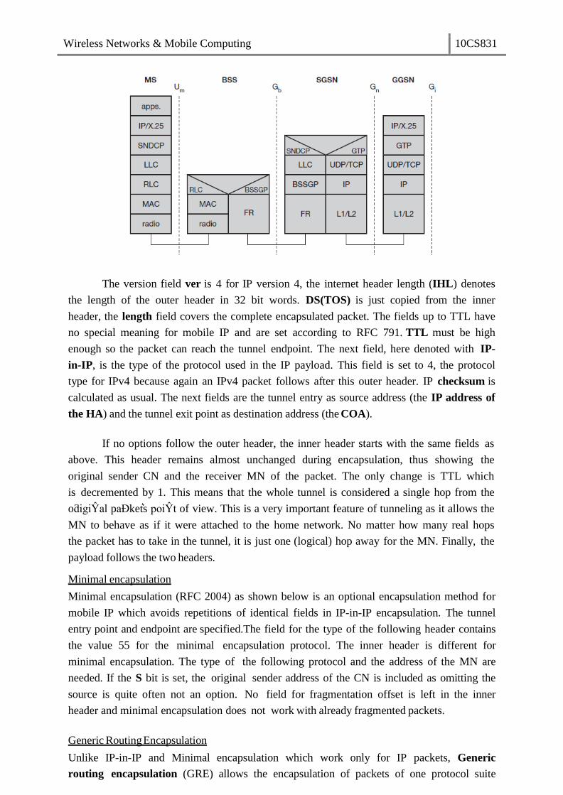
Wireless Networks & Mobile Computing 10CS831
The version field ver is 4 for IP version 4, the internet header length (IHL) denotes
the length of the outer header in 32 bit words. DS(TOS) is just copied from the inner
header, the length field covers the complete encapsulated packet. The fields up to TTL have
no special meaning for mobile IP and are set according to RFC 791. TTL must be high
enough so the packet can reach the tunnel endpoint. The next field, here denoted with IP-
in-IP, is the type of the protocol used in the IP payload. This field is set to 4, the protocol
type for IPv4 because again an IPv4 packet follows after this outer header. IP checksum is
calculated as usual. The next fields are the tunnel entry as source address (the IP address of
the HA) and the tunnel exit point as destination address (the COA).
If no options follow the outer header, the inner header starts with the same fields as
above. This header remains almost unchanged during encapsulation, thus showing the
original sender CN and the receiver MN of the packet. The only change is TTL which
is decremented by 1. This means that the whole tunnel is considered a single hop from the
oƌigiŶal paĐkets poiŶt of view. This is a very important feature of tunneling as it allows the
MN to behave as if it were attached to the home network. No matter how many real hops
the packet has to take in the tunnel, it is just one (logical) hop away for the MN. Finally, the
payload follows the two headers.
Minimal encapsulation
Minimal encapsulation (RFC 2004) as shown below is an optional encapsulation method for
mobile IP which avoids repetitions of identical fields in IP-in-IP encapsulation. The tunnel
entry point and endpoint are specified.The field for the type of the following header contains
the value 55 for the minimal encapsulation protocol. The inner header is different for
minimal encapsulation. The type of the following protocol and the address of the MN are
needed. If the S bit is set, the original sender address of the CN is included as omitting the
source is quite often not an option. No field for fragmentation offset is left in the inner
header and minimal encapsulation does not work with already fragmented packets.
Generic Routing Encapsulation
Unlike IP-in-IP and Minimal encapsulation which work only for IP packets, Generic
routing encapsulation (GRE) allows the encapsulation of packets of one protocol suite

Wireless Networks & Mobile Computing 10CS831
into the payload portion of a packet of another protocol suite as shown below. The packet of
one protocol suite with the original packet header and data is taken and a new GRE header
is prepended. Together this forms the new data part of the new packet. Finally, the header
of the second protocol suite is put in front.The following figure shows the fields of a packet
inside the tunnel between HA and COA using GRE as an encapsulation scheme according
to RFC 1701. The outer header is the standard IP header with HA as source address and
COA as destination address. The protocol type used in this outer IP header is 47 for GRE.
The GRE header starts with several flags indicating if certain fields are present or not.
A minimal GRE header uses only 4 bytes. The C bit indicates if the checksum field is present
and contains valid information. If C is set, the checksum field contains a valid IP checksum
of the GRE header and the payload. The R bit indicates if the offset and routing fields are
present and contain valid information. The offset represents the offset in bytes for the first
source routing entry. The routing field, if present, has a variable length and contains fields
for source routing. GRE also offers a key field which may be used for authentication. If this
field is present, the K bit is set. The sequence number bit S indicates if the sequence
number field is present, if the s bit is set, strict source routing is used.
The recursion control field (rec.) is an important field that additionally distinguishes
GRE from IP-in-IP and minimal encapsulation. This field represents a counter that shows the
number of allowed recursive encapsulations. The default value of this field should be 0, thus
allowing only one level of encapsulation. The following reserved fields must be zero and are
ignored on reception. The version field contains 0 for the GRE version. The following 2 byte
protocol field represents the protocol of the packet following the GRE header. The standard
header of the original packet follows with the source address of the correspondent node
and the destination address of the mobile node.
A simplified header of GRE following RFC 2784 is shownbelow.
The field C indicates again if a checksum is present. The next 5 bits are set to zero, then 7
reserved bits follow. The version field contains the value zero. The protocol type, again,
defines the protocol of the payload following RFC 3232. If the flag C is set, then checksum
field and a field called reserved1 follows. The latter field is constant zero set to zero follow.
Optimizations
If a scenario occurs, where if the MN is in the same subnetwork as the node to which it is
communicating and HA is on the other side of the world. It is called triangular routing
problem as it causes unnecessary overheads for the network between CN and the HA.
A solution to this problem is to inform the CN of the current location of the MN. The CN can
learn the location by caching it in a binding cache, which is a part of the routing table for the
CN. HA informs the CN of the location. It needs four additional messages:
Binding Request: It is sent by the node that wants to know the current location of an
MN to the HA. HA checks if it is allowed to reveal the location and then sends back a
binding update
Binding update: It is sent by the HA to the CN revealing the current location of an MN. It

Wireless Networks & Mobile Computing 10CS831
contains the fixed IP address of the MN and the COA. This message can request an
acknowledgement.
Binding acknowledgement: If requested, a node returns this acknowledgement after
receiving a binding update message
Binding warning: A node sends a binding warning if it decapsulates a packet for an MN,
ďut it is Ŷote the ĐuƌƌeŶt FA of this MN. It ĐoŶtaiŶs MN s hoŵe addƌess aŶd a
target nodes address. The recipient can be the HA, so the HA now sends a binding
update to the node that obviously has a wrong COA for the MN.
The following figure shows how the four additional messages are used together if an MN
changes its FA. The CN can request the current location from the HA. If allowed by the MN,
the HA returns the COA of the MN via an update message. The CN acknowledges this
update message and stores the mobility binding. Now the CN can send its data directly
to the current foreign agent FAold. FAold forwards the packets to the MN. This scenario
shows a COA located at an FA. Encapsulation of data for tunneling to the COA is now done
by the CN, not the HA.
The MN might now change its location and register with a new foreign agent,
FAnew. This registration is also forwarded to the HA to update its location database.
Furthermore, FAnew informs FAold aďout the Ŷeǁ ƌegistƌatioŶ of MN. MNs ƌegistƌatioŶ
ŵessage contains the address of FAold for this purpose. Passing this information is achieved
via an update message, which is acknowledged by FAold.
Without the information provided by the new FA, the old FA would not get to know
anything about the new location of MN. In this case, CN does not know anything about the
new location, so it still tunnels its packets for MN to the old FA, FAold. This FA now
notices packets with destination MN, but also knows that it is not the current FA of MN.
FAold might now forward these packets to the new COA of MN which is FAnew in
this example. This forwarding of packets is another optimization of the basic Mobile IP
providing smooth handovers. Without this optimization, all packets in transit would be
lost while the MN moves from one FA to another.
To tell CN that it has a stale binding cache, FAold sends, a binding warning message
to CN. CN then requests a binding update. (The warning could also be directly sent to the
HA triggering an update). The HA sends an update to inform the CN about the new
location, which is acknowledged. Now CN can send its packets directly to FAnew, again
avoiding triangular routing. Unfortunately, this optimization of mobile IP to avoid
triangular routing causes several security problems
Reverse Tunnelling
The reverse path from MS to the CN looks quite simple as the MN can directly send its
packets to the CN as in any other standard IP situation. The destination address in the
packets is that of CN. But it has some problems explained below:-
Quite often firewalls are designed to only allow packets with topologically correct
addresses to pass to provide simple protection against misconfigured systems of
unknown addresses. However, MN still sends packets with its fixed IP address as source
Wireless Networks & Mobile Computing 10CS831
which is not topologically correct in a foreign network. Firewalls often filter packets
coming from outside containing a source address from computers of the internal
network. This also implies that an MN cannot send a packet to a computer residing in its
home network.
While the nodes in the home network might participate in a multi-cast group, an MN in
a foreign network cannot transmit multi-cast packets in a way that they emanate from
its home network without a reverse tunnel. The foreign network might not even provide
the technical infrastructure for multi-cast communication (multi-cast backbone, Mbone).
If the MN moves to a new foreign network, the older TTL might be too low for the
packets to reach the same destination nodes as before. Mobile IP is no longer
transparent if a user has to adjust the TTL while moving. A reverse tunnel is needed that
represents only one hop, no matter how many hops are really needed from the foreign to
the home network
Based on the above considerations, reverse tunnelling is defined as an extension to mobile
IP (per RFC 2344). It was designed backward compatible to mobile IP and defines
topologically correct reverse tunnelling to handle the above stated problems.
Packet Forwarding Reverse Tunnel
Reverse tunneling does not solve
problems with firewalls, the reverse tunnel can be abused to circumvent security
mechanisms (tunnel hijacking)
optimization of data paths, i.e. packets will be forwarded through the tunnel via the HA to
a sender (double triangular routing)
IPv6
The design of Mobile IP support in IPv6 (Mobile IPv6) benefits both from the experiences
gained from the development of Mobile IP support in IPv4, and from the opportunities
provided by IPv6. Mobile IPv6 thus shares many features with Mobile IPv4, but is integrated
into IPv6 and offers many other improvements. This section summarizes the major
differences between Mobile IPv4 and Mobile IPv6:
There is no need to deploy special routers as "foreign agents", as in Mobile IPv4. Mobile
IPv6 operates in any location without any special support required from the local router.
Support for route optimization is a fundamental part of the protocol, rather than a
nonstandard set of extensions.
Mobile IPv6 route optimization can operate securely even without pre-arranged security
associations. It is expected that route optimization can be deployed on a global scale
between all mobile nodes and correspondent nodes.
Support is also integrated into Mobile IPv6 for allowing route optimization to coexist
efficiently with routers that perform "ingressfiltering"
The IPv6 Neighbor Unreachability Detection assures symmetric reachability between the
mobile node and its default router in the current location.
Most packets sent to a mobile node while away from home in Mobile IPv6 are sent using
an IPv6 routing header rather than IP encapsulation, reducing the amount of resulting

Wireless Networks & Mobile Computing 10CS831
overhead compared to Mobile IPv4.
Mobile IPv6 is decoupled from any particular link layer, as it uses IPv6 Neighbor
Discovery instead of ARP. This also improves the robustness of the protocol.
The use of IPv6 encapsulation (and the routing header) removes the need in Mobile IPv6
to manage "tunnel soft state".
The dynamic home agent address discovery mechanism in Mobile IPv6 returns a single
reply to the mobile node. The directed broadcast approach used in IPv4 returns separate
replies from each home agent.
Dynamic Host Configuration Protocol (DHCP)
DHCP is an automatic configuration protocol used on IP networks. DHCP allows
a computer to join an IP-based network without having a pre-configured IP address. DHCP is
a protocol that assigns unique IP addresses to devices, then releases and renews these
addresses as devices leave and re-join the network. If a new computer is connected to a
network, DHCP can provide it with all the necessary information for full system integration
into the network, e.g., addresses of a DNS server and the default router, the subnet mask,
the domain name, and an IP address. Providing an IP address makes DHCP very attractive for
mobile IP as a source of care-of-addresses.
DHCP is based on a client/server model as shown below. DHCP clients send a request
to a server (DHCPDISCOVER in the example) to which the server responds. A client
sends requests using MAC broadcasts to reach all devices in the LAN. A DHCP relay
might be needed to forward requests across inter-working units to a DHCPserver.
Consider the scenario where there is one client and two servers are present. A typical
initialization of a DHCP client is shown below:
the client broadcasts a DHCPDISCOVER into the subnet. There might be a relay to
forward this broadcast. In the case shown, two servers receive this broadcast and
determine the configuration they can offer to the client. Servers reply to the ĐlieŶts
ƌeƋuest with DHCPOFFER and offer a list of configuration parameters. The client can now
choose one of the configurations offered. The client in turn replies to the servers,
accepting one of the configurations and rejecting the others using DHCPREQUEST. If a
server receives a DHCPREQUEST with a rejection, it can free the reserved configuration
for other possible clients. The server with the configuration accepted by the client now
confirms the configuration with DHCPACK. This completes the initialization phase. If a
client leaves a subnet, it should release the configuration received by the server using
DHCPRELEASE. Now the server can free the context stored for the client and offer the
configuration again. The configuration a client gets from a server is only leased for a certain
amount of time, it has to be reconfirmed from time to time. Otherwise the server will free
the configuration. This timeout of configuration helps in the case of crashed nodes or nodes
moved away without releasing the context.
DHCP is a good candidate for supporting the acquisition of care-of addresses for
mobile nodes. The same holds for all other parameters needed, such as addresses of the
default router, DNS servers, the timeserver etc. A DHCP server should be located in the

Wireless Networks & Mobile Computing 10CS831
subnet of the access point of the mobile node, or at least a DHCP relay should provide
forwarding of the messages. RFC 3118 specifies authentication for DHCP messages so as to
provide protection from malicious DHCP servers. Without authentication, a DHCP server
cannot trust the mobile node and vice versa.

Wireless Networks & Mobile Computing 10CS831
Unit-4
Traditional TCP
The Transmission Control Protocol (TCP) is one of the core protocols of the Internet
protocol suite, often simply referred to as TCP/IP. TCP is reliable, guarantees in-order
delivery of data and incorporates congestion control and flow controlmechanisms.
TCP supports many of the Internet's most
popular application protocols and resulting
applications, including the World Wide Web,
e-mail, File Transfer Protocol and Secure
Shell. In the Internet protocol suite, TCP is
the intermediate layer between the Internet
layer and application layer.
The major responsibilities of TCP in an
active session are to:
• Provide reliable in-order transport of
data: to not allow losses of data.
• Control congestions in the networks: to
not allow degradation of the network
performance,
• Control a packet flow between the
transmitter and the receiver: to not exceed
the receiver's capacity.
TCP uses a number of mechanisms to achieve high performance and avoid 'congestion
collapse', where network performance can fall by several orders of magnitude. These
mechanisms control the rate of data entering the network, keeping the data flow below a
rate that would trigger collapse. There are several mechanisms of TCP that influence the
efficiency of TCP in a mobile environment. Acknowledgments for data sent, or lack of
acknowledgments, are used by senders to implicitly interpret network conditions
between the TCP sender and receiver.
Congestion Control
A transport layer protocol such as TCP has been designed for fixed networks
with fixed end- systems. Congestion may appear from time to time even in
carefully designed networks. The packet buffers of a router are filled and the router
cannot forward the packets fast enough because the sum of the input rates of
packets destined for one output link is higher than the capacity of the output link.
The only thing a router can do in this situation is to drop packets. A dropped packet
is lost for the transmission, and the receiver notices a gap in the packet stream. Now

Wireless Networks & Mobile Computing 10CS831
the receiver does not directly tell the sender which packet is missing, but
continues to acknowledge all in-sequence packets up to the missing one.
The sender notices the missing acknowledgement for the lost packet and
assumes a packet loss due to congestion. Retransmitting the missing packet and
continuing at full sending rate would now be unwise, as this might only increase the
congestion. To mitigate congestion, TCP slows down the transmission rate
dramatically. All other TCP connections experiencing the same congestion do
exactly the same so the congestion is soon resolved.
Slow start
TCPs reaction to a missing acknowledgement is quite drastic, but it is necessary to
get rid of congestion quickly. The behavior TCP shows after the detection of
congestion is called slow start. The sender always calculates a congestion
window for a receiver. The start size of the congestion window is one segment
(TCP packet). The sender sends one packet and waits for acknowledgement. If
this acknowledgement arrives, the sender increases the congestion window by one,
now sending two packets (congestion window = 2). This scheme doubles the
congestion window every time the acknowledgements come back, which takes one
round trip time (RTT). This is called the exponential growth of the congestion
window in the slow start mechanism.
But doubling the
congestion window is too
dangerous. The
exponential growth stops
at the congestion
threshold. As soon as
the congestion window
reaches the congestion
threshold, further
increase of the
transmission rate is only
linear by adding 1 to
the congestion window
each time the
acknowledgements come
back.
Linear increase continues
until a time-out at the sender
occurs due to a missing
acknowledgement, or until
the sender detects a gap in
transmitted data because of
continuous knowledgements

Wireless Networks & Mobile Computing 10CS831
for the same packet. In
either case the sender sets
the congestion threshold to
half of the current
congestion
window. The congestion window itself is set to one segment and the sender starts sending a
single segment. The exponential growth starts once more up to the new congestion threshold,
then the window grows in linear fashion.
Fast retransmit/fast recovery
The congestion threshold can be reduced because of two reasons. First one is if the sender
receives continuous acknowledgements for the same packet. It informs the sender that the
receiver has got all the packets upto the acknowledged packet in the sequence and also the
receiver is receiving something continuously from the sender. The gap in the packet stream is
not due to congestion, but a simple packet loss due to a transmission error. The sender can
now retransmit the missing packet(s) before the timer expires. This behavior is called fast
retransmit. It is an early enhancement for preventing slow-start to trigger on losses not caused
by congestion. The receipt of acknowledgements shows that there is no congestion to justify a
slow start. The sender can continue with the current congestion window. The sender performs a
fast recovery from the packet loss. This mechanism can improve the efficiency of TCP
dramatically. The other reason for activating slow start is a time-out due to a missing
acknowledgement. TCP using fast retransmit/fast recovery interprets this congestion in the
network and activates the slow start mechanism.
The advantage of this method is its simplicity. Minor changes in the MHs software
results in performance increase. No changes are required in FA orCH.
The disadvantage of this scheme is insufficient isolation of packet losses. It mainly
focuses on problems regarding Handover. Also it effects the efficiency when a CH
transmits already delivered packets.
Problems with Traditional TCP in wireless environments
Slow Start mechanism in fixed networks decreases the efficiency of TCP if used with
mobile receivers or senders.
Error rates on wireless links are orders of magnitude higher compared to fixed fiber or
copper links. This makes compensation for packet loss by TCP quite difficult.
Mobility itself can cause packet loss. There are many situations where a soft handover
from one access point to another is not possible for a mobile end-system.
Standard TCP reacts with slow start if acknowledgements are missing, which does not
help in the case of transmission errors over wireless links and which does not really help
during handover. This behavior results in a severe performance degradation of an
unchanged TCP if used together with wireless links or mobile nodes
Classical TCP Improvements

Wireless Networks & Mobile Computing 10CS831
Indirect TCP (I-TCP)
Indirect TCP segments a TCP connection into a fixed part and a wireless part. The following
figure shows an example with a mobile host connected via a wireless link and an access point to
the ǁiƌed iŶteƌŶet ǁheƌe the ĐoƌƌespoŶdeŶt host resides.
Standard TCP is used between the fixed computer and the access point. No computer in
the internet recognizes any changes to TCP. Instead of the mobile host, the access point now
terminates the standard TCP connection, acting as a proxy. This means that the access point is
now seen as the mobile host for the fixed host and as the fixed host for the mobile host.
Between the access point and the mobile host, a special TCP, adapted to wireless links, is used.
However, changing TCP for the wireless link is not a requirement. A suitable place for
segmenting the connection is at the foreign agent as it not only controls the mobility of the
mobile host anyway and can also hand over the connection to the next foreign agent when the
mobile host moves on.
The foreign agent acts as a proxy and relays all data in both directions. If CH
(correspondent host) sends a packet to the MH, the FA acknowledges it and forwards it to the
MH. MH acknowledges on successful reception, but this is only used by the FA. If a packet is lost
on the wireless link, CH doesŶt observe it and FA tries to retransmit it locally to maintain
reliable data transport. If the MH sends a packet, the FA acknowledges it and forwards it to CH.
If the packet is lost on the wireless link, the mobile hosts notice this much faster due to the
lower round trip time and can directly retransmit the packet. Packet loss in the wired network is
now handled by the foreign agent.
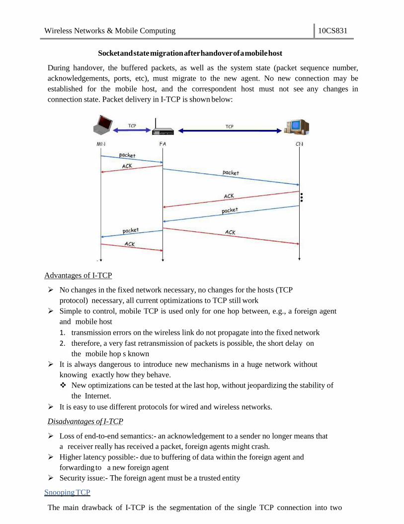
Wireless Networks & Mobile Computing 10CS831
Socket and state migration after handover of a mobile host
During handover, the buffered packets, as well as the system state (packet sequence number,
acknowledgements, ports, etc), must migrate to the new agent. No new connection may be
established for the mobile host, and the correspondent host must not see any changes in
connection state. Packet delivery in I-TCP is shown below:
Advantages of I-TCP
No changes in the fixed network necessary, no changes for the hosts (TCP
protocol) necessary, all current optimizations to TCP still work
Simple to control, mobile TCP is used only for one hop between, e.g., a foreign agent
and mobile host
1. transmission errors on the wireless link do not propagate into the fixed network
2. therefore, a very fast retransmission of packets is possible, the short delay on
the mobile hop s known
It is always dangerous to introduce new mechanisms in a huge network without
knowing exactly how they behave.
New optimizations can be tested at the last hop, without jeopardizing the stability of
the Internet.
It is easy to use different protocols for wired and wireless networks.
Disadvantages of I-TCP
Loss of end-to-end semantics:- an acknowledgement to a sender no longer means that
a receiver really has received a packet, foreign agents might crash.
Higher latency possible:- due to buffering of data within the foreign agent and
forwardingto a new foreign agent
Security issue:- The foreign agent must be a trusted entity
Snooping TCP
The main drawback of I-TCP is the segmentation of the single TCP connection into two
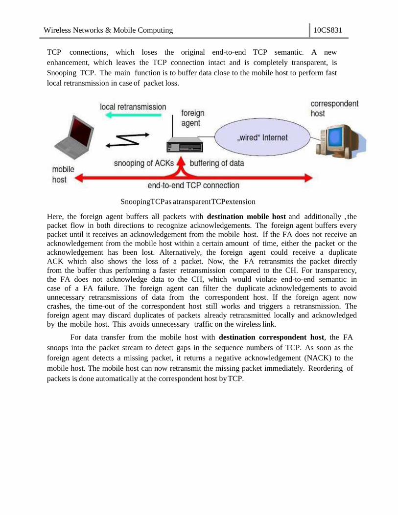
Wireless Networks & Mobile Computing 10CS831
TCP connections, which loses the original end-to-end TCP semantic. A new
enhancement, which leaves the TCP connection intact and is completely transparent, is
Snooping TCP. The main function is to buffer data close to the mobile host to perform fast
local retransmission in case of packet loss.
Snooping TCP as a transparent TCP extension
Here, the foreign agent buffers all packets with destination mobile host and additionally , the
packet flow in both directions to recognize acknowledgements. The foreign agent buffers every
packet until it receives an acknowledgement from the mobile host. If the FA does not receive an
acknowledgement from the mobile host within a certain amount of time, either the packet or the
acknowledgement has been lost. Alternatively, the foreign agent could receive a duplicate
ACK which also shows the loss of a packet. Now, the FA retransmits the packet directly
from the buffer thus performing a faster retransmission compared to the CH. For transparency,
the FA does not acknowledge data to the CH, which would violate end-to-end semantic in
case of a FA failure. The foreign agent can filter the duplicate acknowledgements to avoid
unnecessary retransmissions of data from the correspondent host. If the foreign agent now
crashes, the time-out of the correspondent host still works and triggers a retransmission. The
foreign agent may discard duplicates of packets already retransmitted locally and acknowledged
by the mobile host. This avoids unnecessary traffic on the wireless link.
For data transfer from the mobile host with destination correspondent host, the FA
snoops into the packet stream to detect gaps in the sequence numbers of TCP. As soon as the
foreign agent detects a missing packet, it returns a negative acknowledgement (NACK) to the
mobile host. The mobile host can now retransmit the missing packet immediately. Reordering of
packets is done automatically at the correspondent host by TCP.

Wireless Networks & Mobile Computing 10CS831
Snooping TCP: Packet delivery
Advantages of snooping TCP
The end-to-end TCP semantic is preserved.
Most of the enhancements are done in the foreign agent itself which keeps
correspondent host unchanged.
Handover of state is not required as soon as the mobile host moves to another
foreign agent. Even though packets are present in the buffer, time out at the CH
occurs and the packets are transmitted to the new COA.
No problem arises if the new foreign agent uses the enhancement or not. If not,
the approach automatically falls back to the standard solution.
Disadvantages of snooping TCP
Snooping TCP does not isolate the behavior of the wireless link as well as I-TCP.
Transmission errors may propagate till CH.
Using negative acknowledgements between the foreign agent and the mobile host
assumes additional mechanisms on the mobile host. This approach is no longer
transparent for arbitrary mobile hosts.
Snooping and buffering data may be useless if certain encryption schemes are applied
end- to-end between the correspondent host and mobile host. If encryption is used
above the transport layer, (eg. SSL/TLS), snooping TCP can be used.
Mobile TCP
Both I-TCP and Snooping TCP does not help much, if a mobile host gets
disconnected. The M-TCP (mobile TCP) approach has the same goals as I-TCP and
snooping TCP: to prevent the sender window from shrinking if bit errors or
disconnection but not congestion cause current problems. M-TCP wants to improve
overall throughput, to lower the delay, to maintain end-to-end semantics of TCP, and to

Wireless Networks & Mobile Computing 10CS831
provide a more efficient handover. Additionally, M-TCP is especially adapted to the
problems arising from lengthy or frequent disconnections. M-TCP splits the TCP
connection into two parts as I-TCP does. An unmodified TCP is used on the standard
host-supervisory host (SH) connection, while an optimized TCP is used on the SH-MH
connection.
The SH monitors all packets sent to the MH and ACKs returned from the MH. If
the SH does not receive an ACK for some time, it assumes that the MH is disconnected. It
then chokes the sender by setting the seŶdeƌs window size to 0. Setting the window size
to 0 forces the sender to go into persistent mode, i.e., the state of the sender will not
change no matter how long the receiver is disconnected. This means that the sender will not
try to retransmit data. As soon as the SH (either the old SH or a new SH) detects
connectivity again, it reopens the window of the sender to the old value. The sender
can continue sending at full speed. This mechanism does not require changes to the
seŶdeƌs TCP. The wireless side uses an adapted TCP that can recover from packet loss
much faster. This modified TCP does not use slow start, thus, M-TCP needs a bandwidth
manager to implement fair sharing over the wireless link.
Advantages of M-TCP:
It maintains the TCP end-to-end semantics. The SH does not send any ACK itself but
forwards the ACKs from the MH.
As no buffering is done as in I-TCP, there is no need to forward buffers to a new SH. Lost
packets will be automatically retransmitted to the SH.
Disadvantages of M-TCP:
As the SH does not act as proxy as in I-TCP, packet loss on the wireless link due to bit errors
is propagated to the sender. M-TCP assumes low bit error rates, which is not always a valid
assumption.
A modified TCP on the wireless link not only requires modifications to the MH protocol
software but also new network elements like the bandwidth manager.
Transmission/time-out freezing
Often, MAC layer notices connection problems even before the connection is actually
interrupted from a TCP point of view and also knows the real reason for the interruption. The
MAC layer can inform the TCP layer of an upcoming loss of connection or that the current
interruption is not caused by congestion. TCP can now stop sending and fƌeezes the current
state of its congestion window and further timers. If the MAC layer notices the upcoming
interruption early enough, both the mobile and correspondent host can be informed. With a
fast interruption of the wireless link, additional mechanisms in the access point are needed to
inform the correspondent host of the reason for interruption. Otherwise, the correspondent host
goes into slow start assuming congestion and finally breaks the connection.
As soon as the MAC layer detects connectivity again, it signals TCP that it can resume
operation at exactly the same point where it had been forced to stop. For TCP time simply does
not advance, so no timers expire.

Wireless Networks & Mobile Computing 10CS831
Advantages:
It offers a way to resume TCP connections even after long interruptions of the connection.
It can be used together with encrypted data as it is independent of other TCP mechanisms
such as sequence no or acknowledgements
Disadvantages:
Lots of changes have to be made in software of MH, CH and FA.
Selective retransmission
A very useful extension of TCP is the use of selective retransmission. TCP
acknowledgements are cumulative, i.e., they acknowledge in-order receipt of packets up to
a certain packet. A single acknowledgement confirms reception of all packets upto a
certain packet. If a single packet is lost, the sender has to retransmit everything starting from
the lost packet (go-back-n retransmission). This obviously wastes bandwidth, not just in the
case of a mobile network, but for any network.
Using selective retransmission, TCP can indirectly request a selective retransmission
of packets. The receiver can acknowledge single packets, not only trains of in-sequence
packets. The sender can now determine precisely which packet is needed and can
retransmit it. The advantage of this approach is obvious: a sender retransmits only the lost
packets. This lowers bandwidth requirements and is extremely helpful in slow wireless links.
The disadvantage is that a more complex software on the receiver side is needed. Also more
buffer space is needed to resequence data and to wait for gaps to be filled.
Transaction-oriented TCP
Assume an application running on the mobile host that sends a short request to a server from
time to time, which responds with a short message and it requires reliable TCP transport of the
packets. For it to use normal TCP, it is inefficient because of the overhead involved. Standard
TCP is made up of three phases: setup, data transfer and
release. First, TCP uses a three-way handshake to
establish the connection. At least one additional packet
is usually needed for transmission of the request, and
requires three more packets to close the connection via a
three-way handshake. So, for sending one data packet,
TCP may need seven packets altogether. This kind of
overhead is acceptable for long sessions in fixed
networks, but is quite inefficient for short messages or
sessions in wireless networks. This led to the
development of transaction-oriented TCP (T/TCP).
T/TCP can combine packets for connection establishment and
connection release with user data packets. This can reduce the
number of packets down to two instead of seven. The obvious
advantage for certain applications is the reduction in the overhead
which standard TCP has for connection setup and connection release.
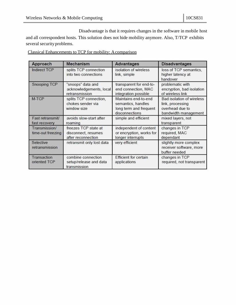
Wireless Networks & Mobile Computing 10CS831
Disadvantage is that it requires changes in the software in mobile host
and all correspondent hosts. This solution does not hide mobility anymore. Also, T/TCP exhibits
several security problems.
Classical Enhancements to TCP for mobility: A comparison

Wireless Networks & Mobile Computing 10CS831
Unit-5
Database
A database is a collection of systematically stored records or information. Databases store data
in a particular logical manner. A mobile device is not always connected to the server or
network; neither does the device retrieve data from a server or a network for each
computation. Rather, the device caches some specific data, which may be required for future
computations, during the interval in which the device is connected to the server or network.
Caching entails saving a copy of select data or a part of a database from a connected system
with a large database. The cached data is hoarded in the mobile device database. Hoarding of
the cached data in the database ensures that even when the device is not connected to the
network, the data required from the database is available forcomputing.
Database Hoarding
Database hoarding may be done at the application tier itself. The following figure shows a
simple architecture in which a mobile device API directly retrieves the data from a database. It
also shows another simple architecture in which a mobile device API directly retrieves the data
from a database through a program, for ex: IBM DB2 Everyplace(DB2e).
(a) API at mobile device sending queries and retrieving data from local database (Tier 1)
(b) API at mobile device retrieving data from database using DB2e (Tier 1)

Wireless Networks & Mobile Computing 10CS831
Both the two architectures belong to the class of one-tier database architecture because the
databases are specific to a mobile device, not meant to be distributed to multiple devices, not
synchronized with the new updates, are stored at the device itself. Some examples are
downloaded ringtones, music etc. IBM DB2 Everyplace (DB2e) is a relational database engine
which has been designed to reside at the device. It supports J2ME and most mobile device
operating systems. DB2e synchronizes with DB2 databases at the synchronization, application,
or enterprise server
The database architecture shown below is for two-tier or multi-tier databases. Here, the
databases reside at the remote servers and the copies of these databases are cached at the
client tiers. This is known as client-server computing architecture.
(a) Distributed data caches in mobile devices
(b) Similar architecture for a distributed cache memory in multiprocessor systems
A cache is a list or database of items or records stored at the device. Databases are
hoarded at the application or enterprise tier, where the database server uses business logic and
connectivity for retrieving the data and then transmitting it to the device. The server provides
and updates local copies of the database at each mobile device connected to it. The computing
API at the mobile device (first tier) uses the cached local copy. At first tier (tier 1), the API uses
the cached data records using the computing architecture as explained above. From tier 2 or
tier 3, the server retrieves and transmits the data records to tier 1 using business logic and
synchronizes the local copies at the device. These local copies function as devicecaches.

Wireless Networks & Mobile Computing 10CS831
The advantage of hoarding is that there is no access latency (delay in retrieving the
queried record from the server over wireless mobile networks). The client device API has
instantaneous data access to hoarded or cached data. After a device caches the data distributed by
the server, the data is hoarded at the device. The disadvantage of hoarding is that the consistency
of the cached data with the database at the server needs to be maintained.
Data Caching
Hoarded copies of the databases at the servers are distributed or transmitted to the mobile
devices from the enterprise servers or application databases. The copies cached at the devices are
equivalent to the cache memories at the processors in a multiprocessor system with a shared
mainmemory and copies of the main memory data stored at different locations.
Cache Access Protocols: A client device caches the pushed (disseminated) data records from a
server. Caching of the pushed data leads to a reduced access interval as compared to the pull (on-
demand) mode of data fetching. Caching of data records can be-based on pushed 'hot records' (the
most needed database records at the client device). Also, caching can be based on the ratio of two
parameters—access probability (at the device) and pushing rates (from the server) for each record. This
method is calledcost-based data replacement or caching.
Pre-fetching: Pre-fetching is another alternative to caching of disseminated data. The process of pre-
fetching entails requesting for and pulling records that may be required later. The client devicecan pre-
fetch instead of caching from the pushed records keeping future needs in view. Pre- fetching reduces
server load. Further, the cost of cache-misses can thus be reduced. The term 'cost of cache-misses'
refers to the time taken in accessing a record at the server in case that record is not found in the device
database when required by the deviceAPI.
A cached record at the client device may be invalidated. This may be due to expiry or modification
of the record at the database server. Cache invalidation is a process by which a cached data item
or record becomes invalid and thus unusable because of modification, expiry, or invalidation at another
computing system or server. Cache invalidation mechanisms are used to synchronize the data at
other processors whenever the cache-data is written (modified) by a processor in a multiprocessor
system, cache invalidation mechanisms are also active in the case of mobile devices having distributed
copies from the server.
A cache consists of several records. Each record is called a cache-line, copies of which can be
stored at other devices or servers. The cache at the mobile devices or server databases at any given
time can be assigned one of four possible tags indicating its state—modified (after rewriting),
exclusive, shared, and invalidated (after expiry or when new data becomes available) at any given
instance. These four states are indicated by the letters M, E, S, and I, respectively (MESI). The states
indicated by the various tags are as follows:
a) The E tag indicates the exclusive state which means that the data record is for internal use
Caching Invalidation Mechanisms

Wireless Networks & Mobile Computing 10CS831
and cannot be used by any other device orserver.
b) The S tag indicates the shared state which indicates that the data record can be used by
others.
c) The M tag indicates the modified state which means that the device cache
d) The I tag indicates the invalidated state which means that the server database no longer has a
copy of the record which was shared and used for computations earlier.
The following figure shows the four possible states of a data record i at any instant in the server
database and its copy at the cache of the mobile device j.
Four possible states (M, E, S, or /) of adata record /at any instance at the server database and
device j cache
Another important factor for cache maintenance in a mobile environment is cache consistency
(also called cache coherence). This requires a mechanism to ensure that a database record is identical at
the server as well as at the device caches and that only the valid cache records are used for
computations.
Cache invalidation mechanisms in mobile devices are triggered or initiated by the server. There are
four possible invalidation mechanisms – Stateless asynchronous, stateless synchronous, stateful
asynchronous and stateful synchronous.
Stateless Asynchronous: A stateless mechanism entails broadcasting of the invalidation of the
cache to all the clients of the server. The server does not keep track of the records stored at the
device caches. It just uniformly broadcasts invalidation reports to all clients irrespective of whether the
device cache holds that particular record or not. The term 'asynchronous' indicates that the
invalidation information for an item is sent as soon as its value changes. The server does notkeep the
information of the present state (whether Emi, Mmi, Smi, or Imi) of a data-record in cache for
broadcasting later. The server advertises the invalidation information only. The client can either
request for a modified copy of the record or cache the relevant record when data is pushed from the
server. The server advertises as and when the corresponding data-record at the server is invalidated

Wireless Networks & Mobile Computing 10CS831
and modified (deleted or replaced).
The advantage of the asynchronous approach is that there are no frequent, unnecessary transfers of
data reports, thus making the mechanism more bandwidth efficient. The disadvantages of this
approach are—(a) every client device gets an invalidation report, whether that client requires that copy or
not and (b) client devices presume that as long as there is no invalidation report, the copy is valid for use
in computations. Therefore, even when there is link failure, the devices may be using the
invalidated data and the server is unaware of state changes at the clients after it sends the
invalidation report.
Stateless Synchronous This is also a stateless mode, i.e., the server has no information regarding
the present state of data records at the device caches and broadcasts to all client devices.
However, unlike the asynchronous mechanism, here the server advertises invalidation information at
periodic intervals as well as whenever the corresponding data-record at server is invalidated or
modified. This method ensures synchronization because even if the in-between period report is not
detected by the device due to a link failure, the device expects the period- end report of invalidation
and if that is not received at the end of the period, then the device sends a request for the same
(deleted or replaced). In case the client device does not get the periodic report due to link failure, it
requests the server to send the report.
The advantage of the synchronous approach is that the client devices receive periodic
information regarding invalidity (and thus validity) of the data caches. The periodic invalidation
reports lead to greater reliability of cached data as update requests for invalid data can be sent to the
server by the device-client. This also helps the server and devices maintain cache consistency
through periodical exchanges. The disadvantages of this mode of cache invalidation are—(a)
unnecessary transfers of data invalidation reports take place, (b) every client device gets an advertised
invalidation report periodically, irrespective of whether that client has a copy of the invalidated data or not,
and (c) during the period between two invalidation reports, the client devices assume that, as long as there
is no invalidation report, the copy is valid for use in computations. Therefore, when there are link
failures, the devices use data which has been invalidated in the in-between period and the server is
unaware of state changes at the clients after it sends the invalidationreport.
Stateful Asynchronous The stateful asynchronous mechanism is also referred to as the AS
(asynchronous stateful) scheme. The term 'stateful' indicates that the cache invalidation reports are
sent only to the affected client devices and not broadcasted to all. The server stores the
information regarding the present state (a record I can have its state as Emi, Mmi, Smi, or Imi) of each
data-record at the client device caches. This state information is stored in the home location cache
(HLC) at the server. The HLC is maintained by an HA (home agent) software. This is similar to the HLR
at the MSC in a mobile network. The client device informs the HA of the state of each record to
enable storage of the same at the HLC. The server transmits the invalidation information as and when
the records are invalidated and it transmits only to the device-clients which are affected by the
invalidation of data. Based on the invalidation information, these device-clients then request the
server for new or modified data to replace the invalidated data. After the data records transmitted
by the server modify the client device cache, the device sends information about the new state to the
serverso that the record of the cache-states at the server is also modified.
The advantage of the stateful asynchronous approach is that the server keeps track of the

Wireless Networks & Mobile Computing 10CS831
state of cached data at the client device. This enables the server to synchronize with the state of records at
the device cache and keep the HLC updated. The stateful asynchronous mode is also advantageous in
that only the affected clients receive the invalidation reports and other devices are not flooded with
irrelevant reports. The disadvantage of the AS scheme is that the client devices presume that, as long
as there is no invalidation report, the copy is valid for use in computations. Therefore, when there is a
link failure, then the devices use invalidated data.
Stateful Synchronous: The server keeps the information of the present state (Emi, Mmi, Smi, or Imi)
of data-records at the client-caches. The server stores the cache record state at the home location
cache (HLC) using the home agent (HA). The server transmits the invalidation information at
periodic intervals to the clients and whenever the data-record relevant to the client is invalidated
or modified (deleted or replaced) at the server. This method ensures synchronization because
even if the in-between period report is not detected by the device due to a link failure, the device
expects the period-end report of invalidation and if it is not received at the end of the period, then the
device requests for the same.
The advantage of the stateful synchronous approach is that there are reports identifying
invalidity (and thus, indirectly, of validity) of data caches at periodic intervals and that the server also
periodically updates the client-cache states stored in the HLC. This enables to synchronize with the
client device when invalid data gets modified and becomes valid. Moreover, since the invalidation
report is sent periodically, if a device does not receive an invalidation report after
the specified period of time, it can request the server to send the report. Each client can thus be
periodically updated of any modifications at the server. When the invalidation report is not received
after the designated period and a link failure is found at the device, the device does not use the invalidated
data. Instead it requests the server for an invalidation update. The disadvantage of the stateful
synchronous approach is the high bandwidth requirement to enable periodic transmission of
invalidation reports to each device and updating requests from each client device.
Data Cache Maintenance in Mobile Environments
Assume that a device needs a data-record during an application. A request must be sent to the
server for the data record (this mechanism is called pulling). The time taken for the application
software to access a particular record is known as access latency. Caching and hoarding the
record at the device reduces access latency to zero. Therefore, data cache maintenance is
necessary in a mobile environment to overcome access latency.
Data cache inconsistency means that data records cached for applications are not invalidated at the
device when modified at the server but not modified at the device. Data cache consistency can be
maintained by the three methods givenbelow:
I. Cache invalidation mechanism (server-initiated case): the server sends invalidation reports on
invalidation of records (asynchronous) or at regular intervals (synchronous).
II. Polling mechanism (client-initiated case): Polling means checking from the server, the state of
data record whether the record is in the valid, invalid, modified, or exclusive state. Each
cached record copy is polled whenever required by the application software during computation. If
the record is found to be modified or invalidated, then the device requests for the modified data
and replaces the earlier cached record copy.

Wireless Networks & Mobile Computing 10CS831
III. Time-to-live mechanism (client-initiated case): Each cached record is assigned a TTL (time-to-live).
The TTL assignment is adaptive (adjustable) previous update intervals of that record. After the
end of the TTL, the cached record copy is polled. If it is modified, then the device requests the
server to replace the invalid cached record with the modified data. When TTL is set to 0, the TTL
mechanism is equivalent to the polling mechanism.
Web Cache Maintenance in Mobile Environments
The mobile devices or their servers can be connected to a web server (e.g., traffic information
server or train information server). Web cache at the device stores the web server data and
maintains it in a manner similar to the cache maintenance for server data described above. If an
application running at the device needs a data record from the web which is not at the web cache, then
there is access latency. Web cache maintenance is necessary in a mobile environment to overcome
access latency in downloading from websites due to disconnections. Web cache consistency can be
maintained by two methods. These are:
I. Time-to-live (TTL) mechanism (client-initiated case): The method is identical to the one
discussed for data cache maintenance.
II. Power-aware computing mechanism (client-initiated case): Each web cache maintained at the
device can also store the CRC (cyclic redundancy check) bits. Assume that there are N cached
bits and n CRC bits. N is much greater than n. Similarly at the server, n CRC bits are stored.
As long as there is consistency between the server and device records, the CRC bits at both are
identical. Whenever any of the records cached at the server is modified, the corresponding
CRC bits at the server are also modified. After the TTL expires or on- demand for the
web cache records by the client API, the cached record CRC is polled and obtained from the
website server. If the n CRC bits at server are found to be modified and the change is found to
be much higher than a given threshold (i.e., a significant change), then the modified part of
the website hypertext or database is retrieved by the clientdevice for use by the API. However, if
the change is minor, then the API uses the previous cache. Since N » n, the power
dissipated in the web cache maintenance method (in which invalidation reports and all
invalidated record bits are transmitted) is much greater than that in the present method (in
which the device polls for the significant change in the CRC bits at server and the records are
transmitted only when there is a significant change in the CRC bits).
Client-server computing is a distributed computing architecture, in which there are two types of
nodes, i.e., the clients and the servers. A server is defined as a computing system, which responds to
requests from one or more clients. A client is defined as a computing system, which requests the
server for a resource or for executing a task. The client can either access the data records at the server
or it can cache these records at the client device. The data can be accessed either on client request or
through broadcasts or distribution from theserver.
The client and the server can be on the same computing system or on different computing
systems. Client-server computing can have N-tier architecture (N= 1, 2 ...). When the client and the
server are on the same computing system then the number of tiers, N = 1. When the client and the server
are on different computing systems on the network, then N = 2. A command interchange protocol
Client-Server Computing

Wireless Networks & Mobile Computing 10CS831
(e.g., HTTP) is used for obtaining the client requests at the server or the server responses at the client.
The following subsections describe client-server computing in 2, 3, or N-tier architectures.
Each tier connects to the other with a connecting, synchronizing, data, or command interchange
protocol.
Two-tier Client-Server Architecture
Multimedia file server in two-tier client-server computing architecture (local copies 1 to j of
imageandvoicehoardingatthemobiledevices)
The following figure shows the application server at the second tier. The data records are
retrieved using business logic and a synchronization server in the application server synchronizes with
the local copies at the mobile devices. Synchronization means that when copies of records at the server-
end are modified, the copies cached at the client devices should also be accordingly modified. The
APIs are designed independent of hardware and software platforms as far as possible as different
devices may have different platforms.
Three-tier Client-Server Architecture
In a three-tier computing architecture, the application interface, the functional logic, and the
database are maintained at three different layers. The database is associated with the enterprise server
tier (tier 3) and only local copies of the database exist at mobile devices. The database connects to
the enterprise server through a connecting protocol. The enterprise server connects the complete databases
on different platforms, for example, Oracle, XML, and IBM DB2.

Wireless Networks & Mobile Computing 10CS831
(a) Localcopies1 to j of databasehoardedat the mobiledevicesusinganenterprisedatabase
connectionsynchronizationserver, which synchronizestherequired localcopiesfor applicationwith the
enterprise database server (b) Mobile device with J2ME or BREW platform, APIs an OS and database
havinglocalcopies
Data records at tier 3 are sent to tier 1 as shown in the figure through a synchronization-cum-
application server at tier 2. The synchronization-cum-application server has synchronization and
server programs, which retrieves data records from the enterprise tier (tier 3) using business logic.
There is an in-between server, called synchronization server, which sends and synchronizes the
copies at the multiple mobile devices. The figure shows that local copies 1 to j of databases are
hoarded at the mobile devices for the applications 1 to j.
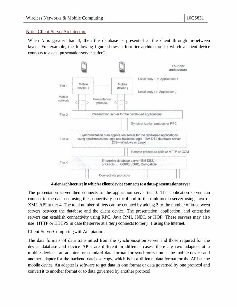
Wireless Networks & Mobile Computing 10CS831
N-tier Client-Server Architecture
When N is greater than 3, then the database is presented at the client through in-between
layers. For example, the following figure shows a four-tier architecture in which a client device
connects to a data-presentationserver at tier 2.
4-tier architecture in which a client device connects to a data-presentation server
The presentation server then connects to the application server tier 3. The application server can
connect to the database using the connectivity protocol and to the multimedia server using Java or
XML API at tier 4. The total number of tiers can be counted by adding 2 to the number of in-between
servers between the database and the client device. The presentation, application, and enterprise
servers can establish connectivity using RPC, Java RMI, JNDI, or HOP. These servers may also
use HTTP or HTTPS in case the server at a tier j connects to tier j+1 using the Internet.
Client-Server Computing with Adaptation
The data formats of data transmitted from the synchronization server and those required for the
device database and device APIs are different in different cases, there are two adapters at a
mobile device—an adapter for standard data format for synchronization at the mobile device and
another adapter for the backend database copy, which is in a different data format for the API at the
mobile device. An adapter is software to get data in one format or data governed by one protocol and
convert it to another format or to data governed by another protocol.

Wireless Networks & Mobile Computing 10CS831
Figure showsan API, database, and adapters ata mobile device and the adaptersat the
synchronization, application, or enterprise servers. Here the adapters are an addition used for
interchangebetweenstandarddataformatsanddataformatsforthe API.
The context of a mobile device represents the circumstances, situations, applications, or
physical environment under which the device is being used. For example, let us assume that a
mobile phone is operating in a busy, congested area. If the device is aware of the surrounding noises,
then during the conversation, it can raise the speaker volume by itself and when the user leaves that
area, the device can again reduce the volume. Also, if there is intermittent loss of connectivity
during the conversation, the device can introduce background noises by itself so that the user does
not feel discomfort due to intermittent periods of silence. This is one example in which the
computing system is aware of the surrounding physical context in which the conversation is
taking place.
A context-aware computing system is one which has user, device, and application
interfaces such that, using these, the system remains aware of the past and present surrounding
situations, circumstances, or actions such as the present mobile network, surrounding devices or
systems, changes in the state of the connecting network, physical parameters such as present time of
the day, presently remaining memory and battery power, presently available nearest connectivity, past
sequence of actions of the device user, past sequence of application or applications, and
previously cached data records, and takes these intoaccount during computations.
Context-aware Computing

Wireless Networks & Mobile Computing 10CS831
Context
The term 'context' refers to the interrelated conditions in which a collection of elements, records,
components, or entities exists or occurs. Each message, data record, element, or entity has a
meaning. But when these are considered along with the conditions that relate them to each other
and to the environment, then they have a wider meaning. Understanding of the context in which a
device is meant to operate, results in better, more efficient computing strategies.
Structural Context: To explain what is meant by structural context let us consider a few examples
of records with structural arrangement. The fields name, address, experience, and achievements of
a person have an individual meaning. However, when put together to form a resume, these
fields acquire a significance beyond their individual meanings. This significance comes from the
fact that they are now arranged in a structure which indicates an interrelationship between them.
The structure of the resume includes the records and their interrelationship and thus defines a
context for these records. Whereby, the records have a new meaning in the context of the resume
(which is a structure). Contexts such as the context of the resume of an individual are called structural
contexts. The context in such cases comes from the structure or format in which the records in a
database areorganized.
Consider another example, this time that of a line in a telephone directory. It has a sequence of
records including a name, an address, and a 10-digit number. Each record has an individual
meaning. But a collection of these records shows an interrelationship and thus defines a context,
i.e., a telephone directory.
Implicit and Explicit Contexts Context may be implicit or explicit. Implicit context provides
for omissions by leaving out unimportant details, takes independent world-views, and performs
alterations in order to cope with incompatible protocols, interfaces, or APIs by transparently
changing the messages. Implicit context uses history to examine call history, to manage
omissions, or to determine recipients and performs contextual message alterations. Consider the
context 'Contacts' which has a set of contacts. The name, e-mail ID, and telephone number are
implicit in a contact in the context Contacts. When a computing device uses a contact to call a
number using a name record, the system takes independent view and uses the telephone number
implicitly and deploys CDMA or GSM protocols for connecting to the mobile network
implicitly. Context CDMA is implicit in defining the records 'Contact'. When a computing system
uses a contact to send an e-mail using a name record, the use of the e-mail ID record is implicit to
the system and the use of SMTP (simple mail transfer protocol) or other mail sending protocol is also
implicit. Name gets automatically altered to e-mail ID when the context is sending of e-mail. The
implicit context also copes with incompatible interfaces, for example, mail sending and receiving
software handling data in different formats. Consider the context document. In document context,
the contact or personal information is an extrinsic context. In context to processing ofa

Wireless Networks & Mobile Computing 10CS831
document, the existence of document author contact information is extrinsic. The contacts
context is imported into the document context to establish interrelationship between document
and contact.
Context-aware Computing
Context-aware computing leads to application-aware computing. This is so because the APIs are
part of the context (implicit or explicit contexts). For example, if context is a contact, the phone-
talk application will adapt itself to use of the telephone number from the 'contact' and to the
use of GSM or CDMA communication.
Use of context in computing helps in reducing possibility of errors. It helps in reducing the
ambiguity in the action(s). It helps in deciding the expected system response on computations.
For example, if name is input in personal biodata context, then the address, experience, and
achievements, which correspond to that name, are also required for computations. This is
because all four are related and needed in biodata context. When name is input in telephone
directory context, then the address and phone number, which correspond to that name, are
also required for computations. This is because all three are related in context to telephone
directory. The name in two different contexts (personal biodata and telephone directory)
during computations needs computations to perform different actions.
Context Types in Context-aware Computing
The five types of contexts that are important in context-aware computing are-physical context,
computing context, user context, temporal context, and structural context.
Physical Context: The context can be that of the physical environment. The
parameters for defining a physical context are service disconnection, light level, noise
level, and signal strength. For example, if there is service disconnection during a
conversation, the mobile device can sense the change in the physical conditions and it
interleaves background noise so that the listener does not feel the effects of the
disconnection. Also, the mobile device can sense the light levels, so during daytime the
display brightness is increased and during night time or in poor light conditions, the
device display brightness is reduced. The physical context changes and the device display
is adjusted accordingly.
Computing Context: The context in a context-aware computing environment may also
be computing context. Computing context is defined by interrelationships and conditions
of the networkconnectivityprotocolinuse(Bluetooth,ZigBee, GSM, GPRS,
orCDMA),bandwidth,and availableresources. Examples of resourcesare keypad, display
unit, printer, and cradle. A cradle is the unit on which the mobile device lies in order to
connect to a computer in the vicinity. Consider a mobile device lying on a cradle. It
discovers the computing context and uses ActiveSyncto synchronize anddownload
from the computer. Whena mobile device lies in the

Wireless Networks & Mobile Computing 10CS831
vicinity of a computer with a Bluetooth interface, it discovers another computing context
resource and uses wireless Bluetooth for connecting to the computer. When it functions
independently and connects to a mobile network, it discovers another computing context
and uses a GSM, CDMA, GPRS, or EDGE connection. The response of the system is
as per the computing context, i.e., the network connectivity protocol.
User Context: The user context is defined user location, user profiles, and persons near
the user. Reza B 'Fardefinesuser-interfaces context states asfollows—'within therealm
of user interfaces, we can define context as the sum of the relationships between the user
interfacecomponents, the condition of the user, the primary intent of thesystem, and all of the
other elements that allow users and computing systems tocommunicate.
Temporal Context: Temporal context defines the interrelation between time and the
occurrence of an event or action. A group of interface components have an intrinsic or
extrinsic temporal context. For example, assume that at an instant the user presses the
switch for dial in a mobile device. At the next instant the device seeks a number as an input.
Then user will consider it in the context of dialling and input the number to be dialled. Now,
assume that at another time the user presses the switch to add a contact in the mobile
device. The device again prompts the user to enter a number as an input. The user will
consider it in context of the number to be added in the contacts and stored in the device for
future use. The device then seeks the name of the contact as the input. Response of the
system in such cases is as per the temporal context. The context for the VUI (voice user
interface) elements also defines a temporal context (depending upon the instances and
sequences in which these occur).
Structural Context: Structural context defines a sequence and structure formed by
the elements or records. Graphic user interface (GUI) elements have structural context.
Structural context may also be extrinsic for some other type of context. Interrelation
amongthe GUIelementsdepends on structuralpositions on the displayscreen. When time is
the context, then the hour and minute elements.
A transaction is the execution of interrelated instructions in a sequence for a specific operation
on a database. Database transaction models must maintain data integrity and must enforce a set
of rules called ACID rules. These rules are as follows:
Atomicity: All operations of a transaction must be complete. In case, a transaction cannot
be completed; it must be undone (rolled back). Operations in a transaction are assumed to
be one indivisible unit (atomic unit).
Transaction Models

Wireless Networks & Mobile Computing 10CS831
Consistency: A transaction must be such that it preserves the integrity constraints and
follows the declared consistency rules for a given database. Consistency means the data is
not in a contradictory state after the transaction.
Isolation: If two transactions are carried out simultaneously, there should not be any
interference between the two. Further, any intermediate results in a transaction should be
invisible to any other transaction.
Durability: After a transaction is completed, it must persist and cannot be aborted or
discarded. For example, in a transaction entailing transfer of a balance from account A to
account B, once the transfer is completed and finished there should be no roll back.
Consider a base class library included in Microsoft.NET. It has a set of computer software
components called ADO.NET (ActiveX Data Objects in .NET). These can be used to access
the data and data services including for access and modifying the data stored in relational
database systems. The ADO.NET transaction model permits three transaction commands:
1. BeginTransaction: It is used to begin a transaction. Any operation after
BeginTransaction is assumed to be a part of the transaction till the
CommitTransaction command or the RollbackTransaction command. An example of a
command is as follows:
connectionA.open();
transA = connectionA.BeginTransaction();
Here connectionA and transA are two distinct objects.
2. Commit: It is used to commit the transaction operations that were carried out after the BeginTransaction command and up to this command. An example of this is
transA.Commit();
All statements between BeginTransaction and commit must execute automatically.
3. Rollback: It is used to rollback the transaction in case an exception is generated
after the BeginTransaction command is executed.
A DBMS may provide for auto-commit mode. Auto-commit mode means the transaction
finished automatically even if an error occurs in between.
Query Processing
Query processing means making a correct as well as efficient execution strategy by query
decomposition and query-optimization. A relational-algebraic equation defines a set of
operations needed during query processing. Either of the two equivalent relational-algebraic
equations given below can be used.

Wireless Networks & Mobile Computing 10CS831
This means first select a column Contacts.cTelNum in a row in Contacts in which
Contacts.cTelNum column equals a column DialledNumbers.dTelNum by crosschecking
and matching the records of a column in Contacts with all the rows of
DialledNumbers. Then in the second step select the row in which Contacts. firstChar =
“R” and the selected cTelNum exists. Then in the third step project cName and
CTelNum.
This means that in first series of step, crosscheck all rows of Contacts and
DialledNumbers and select, after AND operation, the rows in which Contacts.firstchar
= “R” and Contacts.cTelNum = DialledNumbers.dTelNum. Then in the next step
project cName and cTelNum form the selected records.
Query processing architecture
σ the selection operation, and Λ, the AND operation. It is clear that the second set of
operations in query processing is less efficient than the first. Query decomposition of
the first set gives efficiency. Decomposition is done by (i) analysis, (ii) conjunctive and
disjunctive normalization, and (iii) semanticanalysis.
Efficient processing of queries needs optimization of steps for query processing.
Optimization can be based on cost (number of micro-operations in processing) by
evaluating the costs of sets of equivalent expressions. Optimization can also be based on a
heuristic approach consisting of the following steps: perform the selection steps and
projection steps as early as possible and eliminate duplicate operations.
The query optimizer employs (a) query processing plan generator and (b) query processing cost
estimator to provide an efficient plan for query processing.
Data is non-recoverable in case of media failure, intentional attack on the database and
transactions logging data, or physical media destruction. However, data recovery is possible in
other cases. Figure below shows recovery management architecture. It uses a recovery
Data Recovery Process
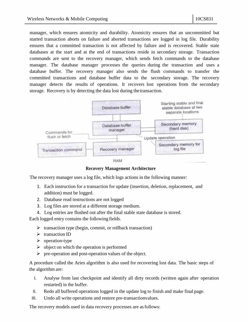
Wireless Networks & Mobile Computing 10CS831
manager, which ensures atomicity and durability. Atomicity ensures that an uncommitted but
started transaction aborts on failure and aborted transactions are logged in log file. Durability
ensures that a committed transaction is not affected by failure and is recovered. Stable state
databases at the start and at the end of transactions reside in secondary storage. Transaction
commands are sent to the recovery manager, which sends fetch commands to the database
manager. The database manager processes the queries during the transaction and uses a
database buffer. The recovery manager also sends the flush commands to transfer the
committed transactions and database buffer data to the secondary storage. The recovery
manager detects the results of operations. It recovers lost operations from the secondary
storage. Recovery is by detecting the data lost during the transaction.
Recovery Management Architecture
The recovery manager uses a log file, which logs actions in the following manner:
1. Each instruction for a transaction for update (insertion, deletion, replacement, and
addition) must be logged.
2. Database read instructions are not logged
3. Log files are stored at a different storage medium.
4. Log entries are flushed out after the final stable state database is stored.
Each logged entry contains the following fields.
transaction type (begin, commit, or rollback transaction)
transaction ID
operation-type
object on which the operation is performed
pre-operation and post-operation values of the object.
A procedure called the Aries algorithm is also used for recovering lost data. The basic steps of
the algorithm are:
I. Analyse from last checkpoint and identify all dirty records (written again after operation
restarted) in the buffer.
II. Redo all buffered operations logged in the update log to finish and make final page.
III. Undo all write operations and restore pre-transactionvalues.
The recovery models used in data recovery processes are as follows:

Wireless Networks & Mobile Computing 10CS831
I. The full recovery model creates back up of the database and incremental backup of the
changes. All transactions are logged from the last backup taken for the database.
II. The bulk logged recovery model entails logging and taking backup of bulk data record
operations but not the full logging and backup. Size of bulk logging is kept to the
minimum required. This improves performance. We can recover the database to the
point of failure by restoring the database with the bulk transaction log file backup. This
is unlike the full recovery model in which all operations are logged.
III. The simple recovery model prepares full backups but the incremental changes are not
logged. We can recover the database to the most recent backup of the givendatabase.
Wireless Networks & Mobile Computing 10CS831
Unit-6
Data Dissemination: Communications asymmetry, classification of new data delivery
mechanisms, push-based mechanisms, pull-based mechanisms, hybrid mechanisms, selective
tuning (indexing) techniques.
Ongoing advances in communications including the proliferation of internet, development of
mobile and wireless networks, high bandwidth availability to homes have led to development
of a wide range of new-information centered applications. Many of these applications involve
data dissemination, i.e. delivery of data from a set of producers to a larger set of consumers.
Data dissemination entails distributing and pushing data generated by a set of
computing systems or broadcasting data from audio, video, and data services. The output data is
sent to the mobile devices. A mobile device can select, tune and cache the required data
items, which can be used for application programs.
Efficient utilization of wireless bandwidth and battery power are two of the most
important problems facing software designed for mobile computing. Broadcast channels are
attractive in tackling these two problems in wireless data dissemination. Data disseminated
through broadcast channels can be simultaneously accessed by an arbitrary number of mobile
users, thus increasing the efficiency of bandwidth usage.
Communications Asymmetry
One key aspect of dissemination-based applications is their inherent communications
asymmetry. That is, the communication capacity or data volume in the downstream direction
(from servers-to-clients) is much greater than that in the upstream direction (from clients-to-
servers). Content delivery is an asymmetric process regardless of whether it is performed over a
symmetric channel such as the internet or over an asymmetric one, such as cable television
(CATV) network. Techniques and system architectures that can efficiently support asymmetric
applications will therefore be a requirement for futureuse.
Mobile communication between a mobile device and a static computer system is
intrinsically asymmetric. A device is allocated a limited bandwidth. This is because a large
number of devices access the network. Bandwidth in the downstream from the server to the
device is much larger than the one in the upstream from the device to the server. This is
because mobile devices have limited power resources and also due to the fact that faster data
transmission rates for long intervals of time need greater power dissipation from the devices. In
GSM networks data transmission rates go up to a maximum of 14.4 kbps for both uplink and
downlink. The communication is symmetric and this symmetry can be maintained because
GSM is only used for voice communication.
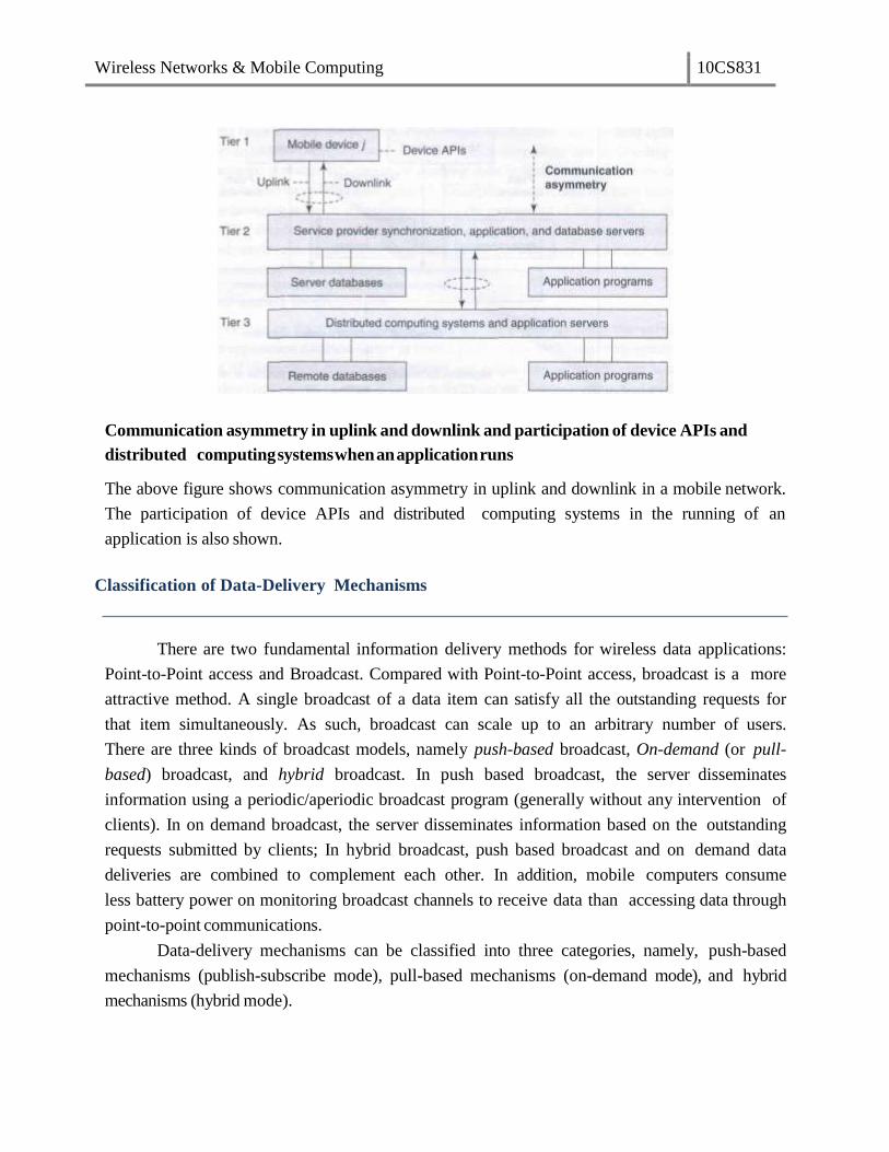
Wireless Networks & Mobile Computing 10CS831
Communication asymmetry in uplink and downlink and participation of device APIs and
distributed computing systems when an application runs
The above figure shows communication asymmetry in uplink and downlink in a mobile network.
The participation of device APIs and distributed computing systems in the running of an
application is also shown.
Classification of Data-Delivery Mechanisms
There are two fundamental information delivery methods for wireless data applications:
Point-to-Point access and Broadcast. Compared with Point-to-Point access, broadcast is a more
attractive method. A single broadcast of a data item can satisfy all the outstanding requests for
that item simultaneously. As such, broadcast can scale up to an arbitrary number of users.
There are three kinds of broadcast models, namely push-based broadcast, On-demand (or pull-
based) broadcast, and hybrid broadcast. In push based broadcast, the server disseminates
information using a periodic/aperiodic broadcast program (generally without any intervention of
clients). In on demand broadcast, the server disseminates information based on the outstanding
requests submitted by clients; In hybrid broadcast, push based broadcast and on demand data
deliveries are combined to complement each other. In addition, mobile computers consume
less battery power on monitoring broadcast channels to receive data than accessing data through
point-to-point communications.
Data-delivery mechanisms can be classified into three categories, namely, push-based
mechanisms (publish-subscribe mode), pull-based mechanisms (on-demand mode), and hybrid
mechanisms (hybrid mode).

Wireless Networks & Mobile Computing 10CS831
Push-based Mechanisms
The server pushes data records from a set of distributed computing systems. Examples are
advertisers or generators of traffic congestion, weather reports, stock quotes, and news reports.
The following figure shows a push-based data-delivery mechanism in which a server or computing
system pushes the data records from a set of distributed computing systems. The data records
are pushed to mobile devices by broadcasting without any demand. The push mode is also
known as publish-subscribe mode in which the data is pushed as per the subscription for a push
service by a user. The subscribed query for a data record is taken as perpetual query till the user
unsubscribe to that service. Data can also be pushed without user subscription.
Push-baseddata-deliverymechanism
Push-based mechanisms function in the following manner:
1. A structure of data records to be pushed is selected. An algorithm provides
an adaptable multi-level mechanism that permits data items to be pushed
uniformly or non-uniformly after structuring them according to their relative
importance.
2. Data is pushed at selected time intervals using an adaptive algorithm. Pushing
only once saves bandwidth. However, pushing at periodic intervals is
important because it provides the devices that were disconnected at the time
of previous push with a chance to cache the data when it is pushed again.
3. Bandwidths are adapted for downlink (for pushes) using an algorithm. Usually higher
bandwidth is allocated to records having higher number of subscribers or to
those with higher access probabilities.
4. A mechanism is also adopted to stop pushes when a device is handed over to
another cell.
The application-distribution system of the service provider uses these algorithms and adopts
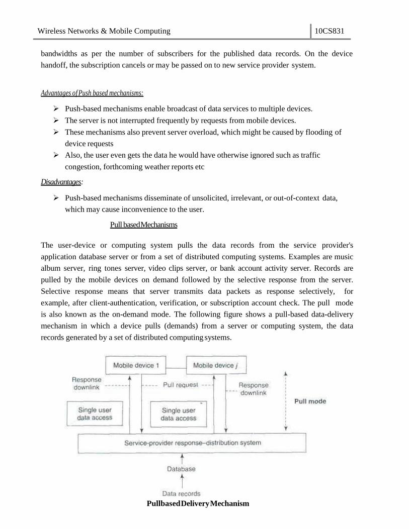
Wireless Networks & Mobile Computing 10CS831
bandwidths as per the number of subscribers for the published data records. On the device
handoff, the subscription cancels or may be passed on to new service provider system.
Advantages of Push based mechanisms:
Push-based mechanisms enable broadcast of data services to multiple devices.
The server is not interrupted frequently by requests from mobile devices.
These mechanisms also prevent server overload, which might be caused by flooding of
device requests
Also, the user even gets the data he would have otherwise ignored such as traffic
congestion, forthcoming weather reports etc
Disadvantages:
Push-based mechanisms disseminate of unsolicited, irrelevant, or out-of-context data,
which may cause inconvenience to the user.
Pull based Mechanisms
The user-device or computing system pulls the data records from the service provider's
application database server or from a set of distributed computing systems. Examples are music
album server, ring tones server, video clips server, or bank account activity server. Records are
pulled by the mobile devices on demand followed by the selective response from the server.
Selective response means that server transmits data packets as response selectively, for
example, after client-authentication, verification, or subscription account check. The pull mode
is also known as the on-demand mode. The following figure shows a pull-based data-delivery
mechanism in which a device pulls (demands) from a server or computing system, the data
records generated by a set of distributed computing systems.
Pullbased Delivery Mechanism

Wireless Networks & Mobile Computing 10CS831
Pull-based mechanisms function in the following manner:
1. The bandwidth used for the uplink channel depends upon the number of pull requests.
2. A pull threshold is selected. This threshold limits the number of pull requests in a given
period of time. This controls the number of server interruptions.
3. A mechanism is adopted to prevent the device from pulling from a cell,
which has handed over the concerned device to another cell. On device
handoff, the subscription is cancelled or passed on to the new service provider
cell
In pull-based mechanisms the user-device receives data records sent by server on demand only.
Advantages of Pull based mechanisms:
With pull-based mechanisms, no unsolicited or irrelevant data arrives at the device and
the relevant data is disseminated only when the user asks for it.
Pull-based mechanisms are the best option when the server has very little contention and is
able to respond to many device requests within expected time intervals.
Disadvantages:
The server faces frequent interruptions and queues of requests at the server may cause
congestion in cases of sudden rise in demand for certain data record.
In on-demand mode, another disadvantage is the energy and bandwidth required for
sending the requests for hot items and temporal records
Hybrid Mechanisms
A hybrid data-delivery mechanism integrates pushes and pulls. The hybrid mechanism is
also known as interleaved-push-and-pull (IPP) mechanism. The devices use the back channel to
send pull requests for records, which are not regularly pushed by the front channel. The front
channel uses algorithms modeled as broadcast disks and sends the generated interleaved responses to
the pull requests. The user device or computing system pulls as well receives the pushes of the
data records from the service provider's application server or database server or from a set of
distributed computing systems. Best example would be a system for advertising and selling
music albums. The advertisements are pushed and the mobile devices pull for buying the album.
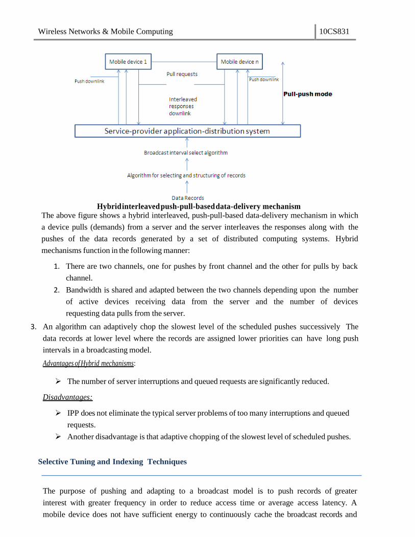
Wireless Networks & Mobile Computing 10CS831
Hybrid interleaved push-pull-based data-delivery mechanism
The above figure shows a hybrid interleaved, push-pull-based data-delivery mechanism in which
a device pulls (demands) from a server and the server interleaves the responses along with the
pushes of the data records generated by a set of distributed computing systems. Hybrid
mechanisms function in the following manner:
1. There are two channels, one for pushes by front channel and the other for pulls by back
channel.
2. Bandwidth is shared and adapted between the two channels depending upon the number
of active devices receiving data from the server and the number of devices
requesting data pulls from the server.
3. An algorithm can adaptively chop the slowest level of the scheduled pushes successively The
data records at lower level where the records are assigned lower priorities can have long push
intervals in a broadcasting model.
Advantages of Hybrid mechanisms:
The number of server interruptions and queued requests are significantly reduced.
Disadvantages:
IPP does not eliminate the typical server problems of too many interruptions and queued
requests.
Another disadvantage is that adaptive chopping of the slowest level of scheduled pushes.
Selective Tuning and Indexing Techniques
The purpose of pushing and adapting to a broadcast model is to push records of greater
interest with greater frequency in order to reduce access time or average access latency. A
mobile device does not have sufficient energy to continuously cache the broadcast records and
Wireless Networks & Mobile Computing 10CS831
hoard them in its memory. A device has to dissipate more power if it gets each pushed item and
caches it. Therefore, it should be activated for listening and caching only when it is going to
receive the selected data records or buckets of interest. During remaining time intervals, that is,
when the broadcast data buckets or records are not of its interest, it switches to idle or power
down mode.
Selective tuning is a process by which client device selects only the required pushed
buckets or records, tunes to them, and caches them. Tuning means getting ready for caching at
those instants and intervals when a selected record of interest broadcasts. Broadcast data has a
structure and overhead. Data broadcast from server, which is organized into buckets, is
interleaved. The server prefixes a directory, hash parameter (from which the device finds the
key), or index to the buckets. These prefixes form the basis of different methods of selective tuning.
Access time (taccess) is the time interval between pull request from device and reception of
response from broadcasting or data pushing or responding server. Two important factors affect
taccess – (i) number and size of the records to be broadcast and (ii) directory- or cache-miss factor
(if there is a miss then the response from the server can be received only in subsequent
broadcast cycle or subsequent repeat broadcast in the cycle).
Directory Method
One of the methods for selective tuning involves broadcasting a directory as
overhead at the beginning of each broadcast cycle. If the interval between the start of
the broadcast cycles is T, then directory is broadcast at each successive intervals of T.
A directory can be provided which record or remaining part of the record relative
to the location of hash and, thus, the time interval for wait before the record can be
tuned and cached.
3. Assume that a broadcast cycle pushes the hashing parameters H(Rí) [H and
S] and record Rí. The functions H and S help in tuning to the H(Rí) and
hence to Rí as follows—H gives a key which in turn gives the location of
H(Rí) in the broadcast data. In case H generates a key that does not provide
the location of H(Rí) by itself, then the device computes the location from S
after the location of H(Rí). That location has the sequential records Rí and
the devices tunes to the records from these locations.
4. In case the device misses the record in first cycle, it tunes and caches that in
next or some other cycle.
Index-Based Method
Indexing is another method for selective tuning. Indexes temporarily map the location of the
buckets. At each location, besides the bits for the bucket in record of interest data, an offset
value may also be specified there. While an index maps to the absolute location from the
beginning of a broadcast cycle, an offset index is a number which maps to the relative location

Wireless Networks & Mobile Computing 10CS831
after the end of present bucket of interest. Offset means a value to be used by the device along
with the present location and calculate the wait period for tuning to the next bucket. All
buckets have an offset to the beginning of the next indexed bucket or item.
Indexing is a technique in which each data bucket, record, or record block of interest is
assigned an index at the previous data bucket, record, or record block of interest to enable the
device to tune and cache the bucket after the wait as per the offset value. The server transmits
this index at the beginning of a broadcast cycle as well as with each bucket corresponding to
data of interest to the device. A disadvantage of using index is that it extends the broadcast cycle
and hence increases taccess.
The index I has several offsets and the bucket type and flag information. A typical index may
consist of the following:
1. Ioffset(1) which defines the offset to first bucket of nearest index.
2. Additional information about Tb, which is the time required for caching the
bucket bits in full after the device tunes to and starts caching the bucket.
This enables transmission of buckets of variable lengths.
3. Ioffset (next) which is the index offset of next bucket record of interest.
4. Ioffset(end) which is the index offset for the end of broadcast cycle and the
start of next cycle. This enables the device to look for next index I after the
time interval as per Ioffset(end). This also permits a broadcast cycle to
consist of variable number of buckets.
5. Itype, which provides the specification of the type of contents of next bucket
to be tuned, that is, whether it has an index value or data.
6. A flag called dirty flag which contains the information whether the indexed
buckets defined by Ioffset(1) and Ioffset(next) are dirty or not. An indexed
bucket being dirty means that it has been rewritten at the server with new values.
Therefore, the device should invalidate the previous caches of these buckets and
update them by tuning to and caching them.
The advantage of having an index is that a device just reads it and selectively tunes to the
data buckets or records of interest instead of reading all the data records and then discarding
those which are not required by it. During the time intervals in which data which is not of
interest is being broadcast, the device remains in idle or power down mode.
Transmission of an index I only once with every broadcast cycle increases access latency of
a record as follows: This is so because if an index is lost during a push due to transmission loss,
then the device must wait for the next push of the same index-record pair. The data tuning time
now increases by an interval equal to the time required for one broadcast cycle. An index
assignment strategy (I, m) is now described. (I, m) indexing means an index I is transmitted m
times during each push of a record. An algorithm is used to adapt a value of m such that it
minimizes access (caching) latency in a given wireless environment which may involve frequent or
Wireless Networks & Mobile Computing 10CS831
less frequent loss of index or data. Index format is adapted to (I, m) with a suitable value of m
chosen as per the wireless environment. This decreases the probability of missing I and hence
the caching of the record of interest
Indexing reduces the time taken for tuning by the client devices and thus conserves their power
resources. Indexing increases access latency because the number of items pushed is more
(equals m times index plus n records).
Distributed Index Based Method
Distributed index-based method is an improvement on the (I, m) method. In this method, there is
no need to repeat the complete index again and again. Instead of replicating the whole index m
times, each index segment in a bucket describes only the offset I' of data items which
immediately follow. Each index I is partitioned into two parts—I' and I". I" consists of
unrepeated k levels (sub-indexes), which do not repeat and I' consists of top I repeated levels
(sub-indexes).
Assume that a device misses I(includes I' and I' once) transmitted at the beginning of the
broadcast cycle. As I' is repeated m - I times after this, it tunes to the pushes by using I', The
access latency is reduced as I' has lesser levels.
Flexible Indexing Method
Assume that a broadcast cycle has number of data segments with each of the segments
having a variable set of records. For example, let n records, Ro to Rn-1, be present in four data
segments, R() to Ri-1, Ri to Rj-1 , Rj to Rj-1 and Rk to Rn-1. Some possible index parameters are
( i ) Iseg, having just 2 bits for the offset, to specify the location of a segment in a broadcast
cycle, (ii) Irec, having just 6 bits for the offset, to specify the location of a record of
interest within a segment of the broadcast cycle, (iii) Ib, having just 4 bits for the offset, to
specify the location of a bucket of interest within a record present in one of the segments of the
broadcast cycle. Flexible indexing method provides dual use of the parameters (e.g., use of
Iseg or Irec in an index segment to tune to the record or buckets of interest) or multi-
parameter indexing (e.g., use of Iseg, Irec, or Ib in an index segment to tune to the bucket of
interest).
Assume that broadcast cycle has m sets of records (called segments). A set of binary bits
defines the index parameter Iseg,. A local index is then assigned to the specific record (or bucket).
Only local index (Irec or Ib) is used in (Iloc, m) based data tuning which corresponds to the case
of flexible indexing method being discussed. The number of bits in a local index is much
smaller than that required when each record is assigned an index. Therefore, the flexible
indexing method proves to be beneficial.
Alternative Methods
Wireless Networks & Mobile Computing 10CS831
Temporal Addressing Temporal addressing is a technique used for pushing in which instead
of repeating I several times, a temporal value is repeated before a data record is
transmitted. When temporal information contained in this value is used instead of address,
there can be effective synchronization of tuning and caching of the record of interest in case of non-
uniform time intervals between the successive bits. The device remains idle and starts tuning by
synchronizing as per the temporal (time)-information for the pushed record. Temporal
information gives the time at which cache is scheduled. Assume that temporal address is 25675
and each address corresponds to wait of 1 ms, the device waits and starts synchronizing the
record after 25675 ms.
Broadcast Addressing: Broadcast addressing uses a broadcast address similar to IP or
multicast address. Each device or group of devices can be assigned an address. The devices
cache the records which have this address as the broadcasting address in a broadcast cycle. This
address can be used along with the pushed record. A device uses broadcast address in place of
the index I to select the data records or sets. Only the addressed device(s) caches the pushed
record and other devices do not select and tune to the record. In place of repeating I several
times, the broadcast address can be repeated before a data record is transmitted. The advantage of
using this type of addressing is that the server addresses to specific device or specific group of
devices.
Use of Headers: A server can broadcast a data in multiple versions or ways. An index or
address only specifies where the data is located for the purpose of tuning. It does not specify the
details of data at the buckets. An alternative is to place a header or a header with an extension
with a data object before broadcasting. Header is used along with the pushed record. The device
uses header part in place of the index / and in case device finds from the header that the
record is of interest, it selects the object and caches it. The header can be useful, for example it
can give information about the type, version, and content modification data or application for
which it is targeted.
(1, m) Index
The (1, m) indexing scheme is an index allocation method where a complete index is
broadcast m times during a broadcast. All buckets have an offset to the beginning of the next
index segment. The first bucket of each index segment has a tuple containing two fields. The
first field contains the key value of the object that was broadcast last and the second field is an
offset pointing to the beginning of the next broadcast. This tuple guides clients who missed the
required object in the current broadcast so that they can tune to the nextbroadcast.
Notes for Indexing Techniques (Prepared by Kancherla Yasesvi, 08071A0522)

Wireless Networks & Mobile Computing 10CS831
The client’s access protocol for retrieving objects with key value
k is as follows:
1. Tune into the current bucket on the broadcast channel. Get the offset to the next index
segment.
2. Go to the doze mode and tune in at the broadcast of the next index segment.
3. Examine the tuple in the first bucket of the index segment. If the target object has been
missed, obtain the offset to the beginning of the next bcast and goto 2; otherwise goto
4.
4. Traverse the index and determine the offset to the target data bucket. This may be
accomplished by successive probes, by following the pointers in the multi-level index.
The client may doze off between two probes.
5. Tune in when the desired bucket is broadcast, and download it(and subsequent ones as
long as their key is k).
Advantage:
1. This scheme has good tuning time.
Disadvantage:
1. The index is entirely replicated m times; this increases the length of the broadcast cycle
and hence the average access time.
The optimal m value that gives minimal average access time is (data file size/index size)1/2
.
There is actually no need to replicate the complete index between successive data blocks. It is
sufficient to make available only the portion of index related to the data buckets which follow
it. This is the approach adopted in all the subsequent indexingschemes.
Tree-based Index/Distributed indexing scheme
In this scheme a data file is associated with a B+
-tree index structure. Since the
broadcast medium is a sequential medium, the data file and index must be flattened so that the
data are index are broadcast following a preorder traversal of the tree. The index comprises
two portions: the first k levels of the index will be partially replicated in the broadcast, and the
remaining levels will not be replicated. The index nodes at the (k+1)th
level are called the non-
replicated roots.
Essentially, each index subtree whose root is a non-replicated root will appear once in

Wireless Networks & Mobile Computing 10CS831
the whole bcast just in front of the set of data segments it indexes. On the other hand, the
nodes at the replicated levels are replicated at the beginning of the first broadcast of each of its
children nodes.
To facilitate selective tuning, each node contains meta-data that help in the traversal of
the trees. All non-replicated buckets contain pointers that will direct the search to the next
copy of its replicated ancestors. On the other hand, all replicated index buckets contain two
tuples that can direct the search to continue in the appropriate segments. The first tuple is a
pair(x, ptrbegin) that indicates that key values less than x have been missed and so search must
continue from the beginning of the next bcast(which is ptrbegin buckets away). The second
pair (y, ptr) indicates that key values greater than or equal to y can be found ptr offset away.
Clearly, if the desired object has key value between x and y, the search can continue as in
conventional search operation.
The client’s access protocol for retrieving objects with key value k is as follows:
1. Tune to the current bucket of the bcast. Get the offset to the next index bucket, and
doze off.
2. Tune to the beginning of the designated bucket and examine the meta-data.
If the desired object has been missed, doze off till the beginning of the
nex
t bcast. Goto 2.
If the desired object is not within the data segment covered by the index bucket,
doze off to the next higher level index bucket. Goto 3.
If the desired object is within the data segment covered by the index bucket,
goto 3.

Wireless Networks & Mobile Computing 10CS831
3. Probe the designated index bucket and follow a sequence of pointers to determine
when the data bucket containing the target object will be broadcast. The client may
doze off in between two probes.
4. Tune in again when the bucket containing objects with key k is broadcast, and download
the bucket (and all subsequent buckets as long as they contain objects with key k).
Advantage:
1. Compared to (1, m) index scheme this scheme has lower access time and its tuning time
is also comparable to that of (1, m) index scheme.
Flexible Indexing Scheme
This scheme splits a sorted list of objects into equal-sized segments, and provides
indexes to navigate through the segments. At the beginning of each segment, there is a control
index which comprises of two components: a global index and a local index. The global index is
used to determine the segment which object may be found, while the local index provides the
offset to the portion within the segment where the object may be found.
Suppose the file is organized into p segments. Then the global index at a segment, says,
has [log2i] (key, ptr) pairs, where i the number of segments in front of and including segment s,
key is an object key, and ptr is an offset. For the first entry, key is the key value of the first data
item in segment s and ptr is the offset to the beginning of the next version. Bold examining this
pair, the client will know if it has missed the data and if so wait till the next bcast. For the jth
entry (j>1), key is the key value of the first data item in the ([log2i/2j-1
] +1)th
segment

Wireless Networks & Mobile Computing 10CS831
following segment s and ptr is the offset to the first data bucket of that segment.
The local index consists of m(key, ptr) pairs that essentially partition each segment
further into m+1 sections. For the first entry, key is the key value of the first data item of
section m+1 and ptr is the offset to that section. For the jth pair, key is the key value of the first
data item of section (m+1-j) and ptr is the offset to the first bucket of that section.
Hence, it is clear that the number of segments and the number of sections per segment
can affect the performance of the scheme. Increasing the number of segments or sections will
increase the length of the broadcast cycle and reduce the tuning time, and vice versa. Thus, the
scheme is flexible in the sense it can be tuned to fit an appliĐatioŶsneeds.
The client’s access protocol for retrieving objects with key value k is as follows:
1. Tune into the channel for a bucket, obtain the offset to the next index segment.
Doze off until the next index segment is broadcast.
2. Examine the global index entries. If the target object belongs to another segment,
get the offset; doze off for appropriate amount of time and goto 2.
3. Examine the local index entries. Obtain the offset to the section where the target data is
stored. Switch to doze mode for appropriate amount of time.
4. Examine objects in the data bucket for the desired object, and download the object.
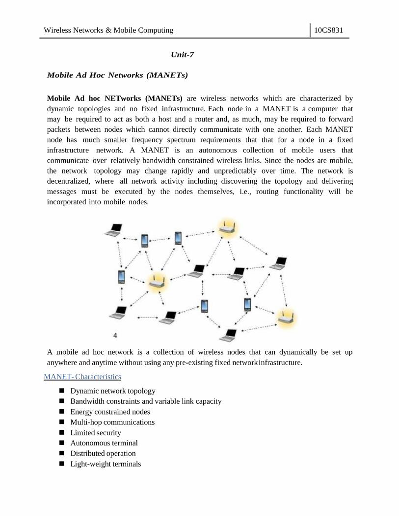
Wireless Networks & Mobile Computing 10CS831
Unit-7
Mobile Ad Hoc Networks (MANETs)
Mobile Ad hoc NETworks (MANETs) are wireless networks which are characterized by
dynamic topologies and no fixed infrastructure. Each node in a MANET is a computer that
may be required to act as both a host and a router and, as much, may be required to forward
packets between nodes which cannot directly communicate with one another. Each MANET
node has much smaller frequency spectrum requirements that that for a node in a fixed
infrastructure network. A MANET is an autonomous collection of mobile users that
communicate over relatively bandwidth constrained wireless links. Since the nodes are mobile,
the network topology may change rapidly and unpredictably over time. The network is
decentralized, where all network activity including discovering the topology and delivering
messages must be executed by the nodes themselves, i.e., routing functionality will be
incorporated into mobile nodes.
A mobile ad hoc network is a collection of wireless nodes that can dynamically be set up
anywhere and anytime without using any pre-existing fixed networkinfrastructure.
MANET- Characteristics
Dynamic network topology
Bandwidth constraints and variable link capacity
Energy constrained nodes
Multi-hop communications
Limited security
Autonomous terminal
Distributed operation
Light-weight terminals

Wireless Networks & Mobile Computing 10CS831
Need for Ad Hoc Networks
Setting up of fixed access points and backbone infrastructure is not always
viable
– Infrastructure may not be present in a disaster area or war zone
– Infrastructure may not be practical for short-range radios; Bluetooth (range ~ 10m)
Ad hoc networks:
– Do not need backbone infrastructure support
– Are easy to deploy
– Useful when infrastructure is absent, destroyed or impractical
Properties of MANETs
MANET enables fast establishment of networks. When anew network is to be established,
the only requirement is to provide a new set of nodes with limited wireless communication
range. A node has limited capability, that is, it can connect only to the nodes which are
nearby. Hence it consumes limited power.
A MANET node has the ability to discover a neighboring node and service. Using a
service discovery protocol, a node discovers the service of a nearby node and communicates
to a remote node in the MANET.
MANET nodes have peer-to-peer connectivity among themselves.
MANET nodes have independent computational, switching (or routing), and communication
capabilities.
The wireless connectivity range in MANETs includes only nearest node connectivity.
The failure of an intermediate node results in greater latency in communicating with the
remote server.
Limited bandwidth available between two intermediate nodes becomes a constraint for the
MANET. The node may have limited power and thus computations need to be energy-
efficient.
There is no access-point requirement in MANET. Only selected access points are provided
for connection to other networks or other MANETs.
MANET nodes can be the iPods, Palm handheld computers, Smartphones, PCs, smart labels,
smart sensors, and automobile-embedded systems\
MANET nodes can use different protocols, for example, IrDA, Bluetooth, ZigBee,
802.11, GSM, and TCP/IP.MANET node performs data caching, saving, andaggregation.
MANET mobile device nodes interact seamlessly when they move with the nearby wireless
nodes, sensor nodes, and embedded devices in automobiles so that the seamless connectivity is
maintained between the devices.
MANET challenges
To design a good wireless ad hoc network, various challenges have to be taken into account:
Dynamic Topology: Nodes are free to move in an arbitrary fashion resulting in the topology
changing arbitrarily. This characteristic demands dynamic configuration of the network.
Limited security: Wireless networks are vulnerable to attack. Mobile ad hoc networks are
more vulnerable as by design any node should be able to join or leave the network at any

Wireless Networks & Mobile Computing 10CS831
time. This requires flexibility and higher openness.
Limited Bandwidth: Wireless networks in general are bandwidth limited. In an ad hoc
network, it is all the more so because there is no backbone to handle or multiplex higher
bandwidth
Routing: Routing in a mobile ad hoc network is complex. This depends on many factors,
including finding the routing path, selection of routers, topology, protocol etc.
Applications of MANETS
The set of applications for MANETs is diverse, ranging from small, static networks that are
constrained by power sources, to large-scale, mobile, highly dynamic networks. The design of
network protocols for these networks is a complex issue. Regardless of the application, MANETs
need efficient distributed algorithms to determine network organization, link scheduling, and
routing. “oŵe of the ŵaiŶ appliĐatioŶ aƌeas of MANETs are:
Military battlefield– soldiers, tanks, planes. Ad- hoc networking would allow the military
to take advantage of commonplace network technology to maintain an information
network between the soldiers, vehicles, and military information headquarters.
Sensor networks – to monitor environmental conditions over a large area
Local level – Ad hoc networks can autonomously link an instant and temporary
multimedia network using notebook computers or palmtop computers to spread and
share information among participants at e.g. conference or classroom. Another
appropriate local level application might be in home networks where devices can
communicate directly to exchange information.
Personal Area Network (PAN) – pervasive computing i.e. to provide flexible
connectivity between personal electronic devices or home appliances. Short-range
MANET can simplify the intercommunication between various mobile devices (such as a
PDA, a laptop, and a cellular phone). Tedious wired cables are replaced with wireless
connections. Such an ad hoc network can also extend the access to the Internet or other
networks by mechanisms e.g. Wireless LAN (WLAN), GPRS, and UMTS.
Vehicular Ad hoc Networks – intelligent transportation i.e. to enable real time vehicle
monitoring and adaptive traffic control
Civilian environments – taxi cab network, meeting rooms, sports stadiums, boats, small

Wireless Networks & Mobile Computing 10CS831
aircraft
Emergency operations – search and rescue, policing and fire fighting and to provide
connectivity between distant devices where the network infrastructure is unavailable.
Ad hoc can be used in emergency/rescue operations for disaster relief efforts, e.g. in
fire, flood, or earthquake. Emergency rescue operations must take place where non-
existing or damaged communications infrastructure and rapid deployment of a
communication network is needed. Information is relayed from one rescue team member
to another over a small hand held.
Routing in MANET’s
Routing in Mobile Ad hoc networks is an important issue as these networks do not have
fixed infrastructure and routing requires distributed and cooperative actions from all nodes in
the network. MANETs provide point to point routing similar to Internet routing. The major
difference between routing in MANET and regular internet is the route discovery mechanism.
Internet routing protocols such as RIP or OSPF have relatively long converge times, which is
acceptable for a wired network that has infrequent topology changes. However, a MANET has
a rapid topology changes due to node mobility making the traditional internet routing protocols
inappropriate. MANET-specific routing protocols have been proposed, that handle topology
changes well, but they have large control overhead and are not scalable for large networks.
Another major difference in the routing is the network address. In internet routing, the network
address (IP address) is hierarchical containing a network ID and a computer ID on that network.
In contrast, for most MANET s the network address is simply an ID of the node in the network
and is not hierarchical. The routing protocol must use the entire address to decide the next
hop.
Some of the fundamental differences between wired networks & ad-hoc networks are:
Asymmetric links: - Routing information collected for one direction is of no use for the other
direction. Many routing algorithms for wired networks rely on a symmetric scenario.
Redundant links: - In wired networks, some redundancy is present to survive link failures
and this redundancy is controlled by a network administrator. In ad-hoc networks, nobody
controls redundancy resulting in many redundant links up to the extreme of a complete
meshed topology.
Interference: - In wired networks, links exist only where a wire exists, and connections are
planned by network administrators. But, in ad-hoc networks links come and go depending
on transmission characteristics, one transmission might interfere with another and nodes
might overhear the transmission of other nodes.
Dynamic topology: - The mobile nodes might move in an arbitrary manner or medium
characteristics might change. This result in frequent changes in topology, so snapshots are
valid only for a very short period of time. So, in ad-hoc networks, routing tables must
somehow reflect these frequent changes in topology and routing algorithms have to be
adopted.
Summary of the difficulties faced for routing in ad-hoc networks
Traditional routing algorithms known from wired networks will not work efficiently or
fail completely. These algorithms have not been designed with a highly dynamic
topology, asymmetric links, or interference in mind.
Routing in wireless ad-hoc networks cannot rely on layer three knowledge alone.
Wireless Networks & Mobile Computing 10CS831
Information from lower layers concerning connectivity or interference can help routing
algorithms to find a good path.
Centralized approaches will not really work, because it takes too long to collect the
current status and disseminate it again. Within this time the topology has already
changed.
Many nodes need routing capabilities. While there might be some without, at least one
router has to be within the range of each node. Algorithms have to consider the limited
battery power of these nodes.
The notion of a connection with certain characteristics cannot work properly. Ad-hoc
networks will be connectionless, because it is not possible to maintain a connection in a
fast changing environment and to forward data following this connection. Nodes have
to make local decisions for forwarding and send packets roughly toward the final
destination.
A last alternative to forward a packet across an unknown topology is flooding. This
approach always works if the load is low, but it is very inefficient. A hop counter is
needed in each packet to avoid looping, and the diameter of the ad-hoc network.
Types of MANET Routing Algorithms:
1. Based on the information used to build routing tables :
• Shortest distance algorithms: algorithms that use distance information to build routing
tables.
• Link state algorithms: algorithms that use connectivity information to build a topology
graph that is used to build routing tables.
2. Based on when routing tables are built:
• Proactive algorithms: maintain routes to destinations even if they are not needed. Some
of the examples are Destination Sequenced Distance Vector (DSDV), Wireless Routing
Algorithm (WRP), Global State Routing (GSR), Source-tree Adaptive Routing
(STAR), Cluster-Head Gateway Switch Routing (CGSR), Topology Broadcast
Reverse Path Forwarding (TBRPF), Optimized Link State Routing (OLSR) etc.
Always maintain routes:- Little or no delay for route determination
Consume bandwidth to keep routes up-to-date
Maintain routes which may never be used
Advantages: low route latency, State information, QoS guarantee related to
connection set-up or other real-time requirements
Disadvantages: high overhead (periodic updates) and route repair depends
on update frequency
• Reactive algorithms: maintain routes to destinations only when they are needed.
Examples are Dynamic Source Routing (DSR), Ad hoc-On demand distance Vector
(AODV), Temporally ordered Routing Algorithm (TORA), Associativity-Based Routing
(ABR) etc
only obtain route information when needed
Advantages: no overhead from periodic update, scalability as long as there is
only light traffic and low mobility.
Disadvantages: high route latency, route caching can reduce latency

Wireless Networks & Mobile Computing 10CS831
• Hybrid algorithms: maintain routes to nearby nodes even if they are not needed and
maintain routes to far away nodes only when needed. Example is Zone Routing Protocol
(ZRP).
Which approach achieves a better trade-off depends on the traffic and mobilitypatterns.
Destination sequence distance vector (DSDV)
Destination sequence distance vector (DSDV) routing is an example of proactive algorithms and
an enhancement to distance vector routing for ad-hoc networks. Distance vector routing is
used as routing information protocol (RIP) in wired networks. It performs extremely poorly with
certain network changes due to the count-to-infinity problem. Each node exchanges its
neighbor table periodically with its neighbors. Changes at one node in the network propagate
slowly through the network. The strategies to avoid this problem which are used in fixed
networks do not help in the case of wireless ad-hoc networks, due to the rapidly changing
topology. This might create loops or unreachable regions within thenetwork.
DSDV adds the concept of sequence numbers to the distance vector algorithm. Each routing
advertisement comes with a sequence number. Within ad-hoc networks, advertisements may
propagate along many paths. Sequence numbers help to apply the advertisements in correct
order. This avoids the loops that are likely with the unchanged distance vector algorithm.
Each node maintains a routing table which stores next hop, cost metric towards each
destination and a sequence number that is created by the destination itself. Each node
periodically forwards routing table to neighbors. Each node increments and appends its
sequence number when sending its local routing table. Each route is tagged with a sequence
number; routes with greater sequence numbers are preferred. Each node advertises a
monotonically increasing even sequence number for itself. When a node decides that a route is
broken, it increments the sequence number of the route and advertises it with infinite metric.
Destination advertises new sequence number.
When X receives information from Y about a route to Z,
Let destination sequence number for Z at X be S(X), S(Y) is sent from Y
If S(X) > S(Y), then X ignores the routing information received from Y
If S(X) = S(Y), and cost of going through Y is smaller than the route known to X, then X
sets Y as the next hop to Z
If S(X) < S(Y), then X sets Y as the next hop to Z, and S(X) is updated to equal S(Y)
Besides being loop-free at all times, DSDV has low memory requirements and a quick
convergence via triggered updates. Disadvantages of DSDV are, large routing overhead, usage
of only bidirectional links and suffers from count to infinity problem.
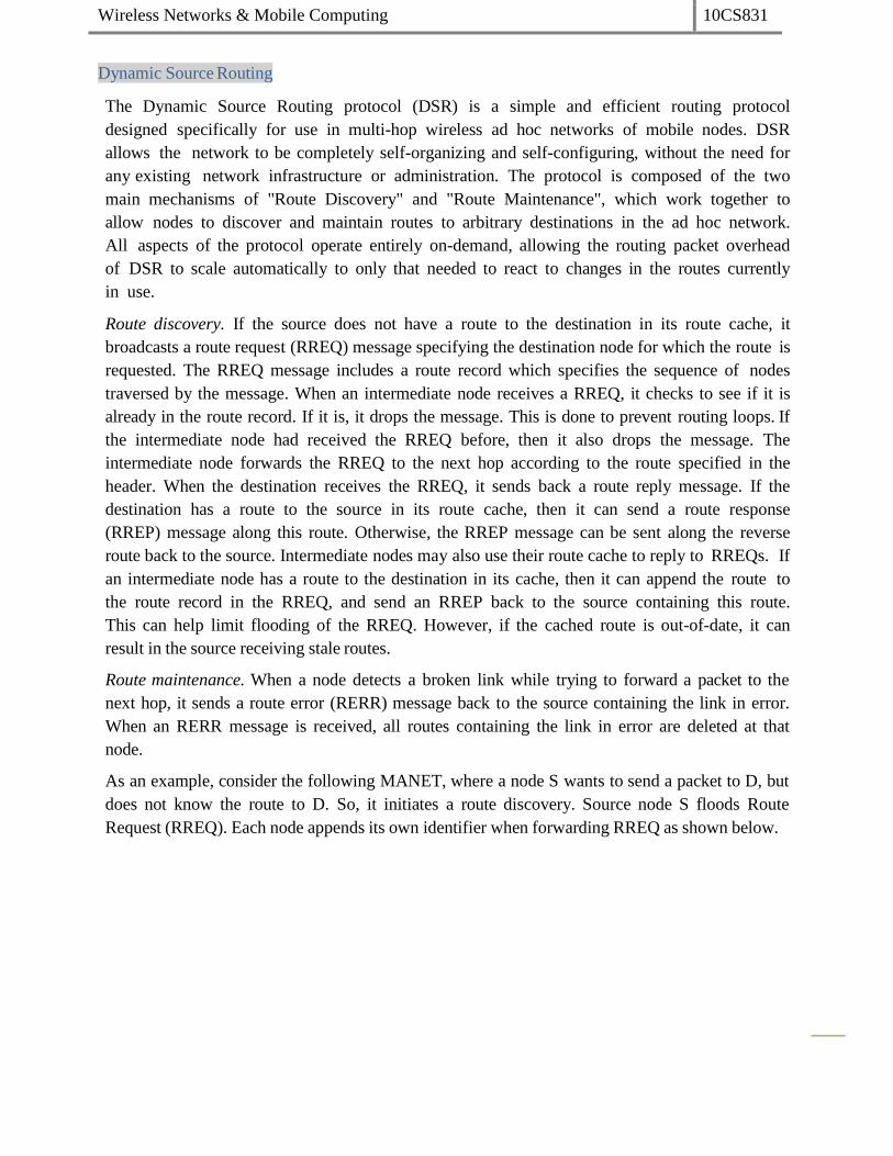
Wireless Networks & Mobile Computing 10CS831
Dynamic Source Routing
The Dynamic Source Routing protocol (DSR) is a simple and efficient routing protocol
designed specifically for use in multi-hop wireless ad hoc networks of mobile nodes. DSR
allows the network to be completely self-organizing and self-configuring, without the need for
any existing network infrastructure or administration. The protocol is composed of the two
main mechanisms of "Route Discovery" and "Route Maintenance", which work together to
allow nodes to discover and maintain routes to arbitrary destinations in the ad hoc network.
All aspects of the protocol operate entirely on-demand, allowing the routing packet overhead
of DSR to scale automatically to only that needed to react to changes in the routes currently
in use.
Route discovery. If the source does not have a route to the destination in its route cache, it
broadcasts a route request (RREQ) message specifying the destination node for which the route is
requested. The RREQ message includes a route record which specifies the sequence of nodes
traversed by the message. When an intermediate node receives a RREQ, it checks to see if it is
already in the route record. If it is, it drops the message. This is done to prevent routing loops. If
the intermediate node had received the RREQ before, then it also drops the message. The
intermediate node forwards the RREQ to the next hop according to the route specified in the
header. When the destination receives the RREQ, it sends back a route reply message. If the
destination has a route to the source in its route cache, then it can send a route response
(RREP) message along this route. Otherwise, the RREP message can be sent along the reverse
route back to the source. Intermediate nodes may also use their route cache to reply to RREQs. If
an intermediate node has a route to the destination in its cache, then it can append the route to
the route record in the RREQ, and send an RREP back to the source containing this route.
This can help limit flooding of the RREQ. However, if the cached route is out-of-date, it can
result in the source receiving stale routes.
Route maintenance. When a node detects a broken link while trying to forward a packet to the
next hop, it sends a route error (RERR) message back to the source containing the link in error.
When an RERR message is received, all routes containing the link in error are deleted at that
node.
As an example, consider the following MANET, where a node S wants to send a packet to D, but
does not know the route to D. So, it initiates a route discovery. Source node S floods Route
Request (RREQ). Each node appends its own identifier when forwarding RREQ as shown below.
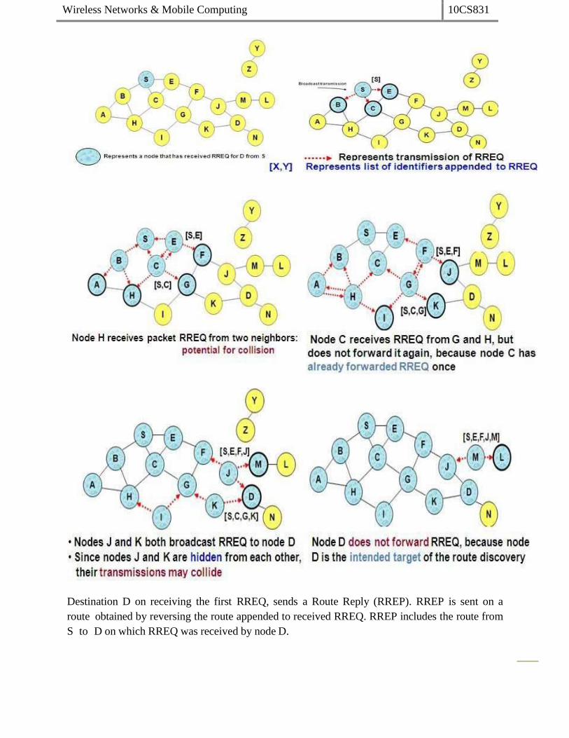
Wireless Networks & Mobile Computing 10CS831
Destination D on receiving the first RREQ, sends a Route Reply (RREP). RREP is sent on a
route obtained by reversing the route appended to received RREQ. RREP includes the route from
S to D on which RREQ was received by node D.

Wireless Networks & Mobile Computing 10CS831
Route Reply can be sent by reversing the route in Route Request (RREQ) only if links are
guaranteed to be bi-directional. If Unidirectional (asymmetric) links are allowed, then RREP may
need a route discovery from S to D. Node S on receiving RREP, caches the route included in the
RREP. When node S sends a data packet to D, the entire route is included in the packet header
hence the name source routing. Intermediate nodes use the source route included in a packet to
determine to whom a packet should be forwarded.
J sends a route error to S along route J-F-E-S when its attempt to forward the data packet S
(with route SEFJD) on J-D fails. Nodes hearing RERR update their route cache to remove link J-D

Wireless Networks & Mobile Computing 10CS831
Advantages of DSR:
Routes maintained only between nodes who need to communicate-- reduces overhead of
route maintenance
Route caching can further reduce route discovery overhead
A single route discovery may yield many routes to the destination, due to intermediate
nodes replying from local caches
Disadvantages of DSR:
Packet header size grows with route length due to source routing
Flood of route requests may potentially reach all nodes in the network
Care must be taken to avoid collisions between route requests propagated by
neighboring nodes -- insertion of random delays before forwarding RREQ
Increased contention if too many route replies come back due to nodes replying using
their local cache-- Route Reply Storm problem. Reply storm may be eased by preventing
a node from sending RREP if it hears another RREP with a shorter route
An intermediate node may send Route Reply using a stale cached route, thus polluting
other caches
An optimization for DSR can be done called as Route Caching. Each node caches a new route it
learns by any means. In the above example, When node S finds route [S,E,F,J,D] to node D,
node S also learns route [S,E,F] to node F. When node K receives Route Request [S,C,G]
destined for node, node K learns route [K,G,C,S] to node S. When node F forwards Route Reply
RREP [S,E,F,J,D], node F learns route [F,J,D] to node D. When node E forwards Data
[S,E,F,J,D] it learns route [E,F,J,D] to node D. A node may also learn a route when it overhears
Data packets. Usage of Route cache can speed up route discovery and can also reduce
propagation of route requests. The disadvantages are, stale caches can adversely affect
performance. With passage of time and host mobility, cached routes may become invalid.

Wireless Networks & Mobile Computing 10CS831
Ad Hoc On-Demand Distance Vector Routing (AODV)
AODV is another reactive protocol as it reacts to changes and maintains only the active routes
in the caches or tables for a pre-specified expiration time. Distance vector means a set of
distant nodes, which defines the path to destination. AODV can be considered as a descendant
of DSR and DSDV algorithms. It uses the same route discovery mechanism used by DSR.
DSR includes source routes in packet headers and resulting large headers can sometimes
degrade performance, particularly when data contents of a packet are small. AODV attempts to
improve on DSR by maintaining routing tables at the nodes, so that data packets do not have to
contain routes. AODV retains the desirable feature of DSR that routes are maintained only
between nodes which need to communicate. However, as opposed to DSR, which uses source
routing, AODV uses hop-by-hop routing by maintaining routing table entries at intermediate
nodes.
Route Discovery. The route discovery process is initiated when a source needs a route to a
destination and it does not have a route in its routing table. To initiate route discovery, the
source floods the network with a RREQ packet specifying the destination for which the route is
requested. When a node receives an RREQ packet, it checks to see whether it is the destination
or whether it has a route to the destination. If either case is true, the node generates an RREP
packet, which is sent back to the source along the reverse path. Each node along the reverse
path sets up a forward pointer to the node it received the RREP from. This sets up a forward
path from the source to the destination. If the node is not the destination and does not have a
route to the destination, it rebroadcasts the RREQ packet. At intermediate nodes duplicate
RREQ packets are discarded. When the source node receives the first RREP, it can begin sending
data to the destination. To determine the relative degree out-of-datedness of routes, each
entry in the node routing table and all RREQ and RREP packets are tagged with a destination
sequence number. A larger destination sequence number indicates a more current (or more
recent) route. Upon receiving an RREQ or RREP packet, a node updates its routing information
to set up the reverse or forward path, respectively, only if the route contained in the RREQ or
RREP packet is more current than its own route.
Route Maintenance. When a node detects a broken link while attempting to forward a packet to
the next hop, it generates a RERR packet that is sent to all sources using the broken link. The
RERR packet erases all routes using the link along the way. If a source receives a RERR
packet and a route to the destination is still required, it initiates a new route discovery process.
Routes are also deleted from the routing table if they are unused for a certain amount of time.

Wireless Networks & Mobile Computing 10CS831

Wireless Networks & Mobile Computing 10CS831

Wireless Networks & Mobile Computing 10CS831
An intermediate node (not the destination) may also send a Route Reply (RREP) provided that it
knows a more recent path than the one previously known to sender S. To determine whether
the path known to an intermediate node is more recent, destination sequence numbers are
used. The likelihood that an intermediate node will send a Route Reply when using AODV is not
as high as DSR. A new Route Request by node S for a destination is assigned a higher
destination sequence number. An intermediate node which knows a route, but with a smaller
sequence number, cannot send Route Reply
When node X is unable to forward packet P (from node S to node D) on link (X,Y), it generates a
RERR message Node X increments the destination sequence number for D cached at node X.
The incremented sequence number N is included in the RERR. When node S receives the RERR,
it initiates a new route discovery for D using destination sequence number at least as large as
N. When node D receives the route request with destination sequence number N, node D will
set its sequence number to N, unless it is already larger than N.

Wireless Networks & Mobile Computing 10CS831
Sequence numbers are used in AODV to avoid using old/broken routes and to determine which
route is newer. Also, it prevents formation of loops.
Assume that A does not know about failure of link C-
D because RERR sent by C is lost.
Now C performs a route discovery for D. Node A
receives the RREQ (say, via path C-E-A)
Node A will reply since A knows a route to D via node B
resulting in a loop (for instance, C-E-A-B-C )
Neighboring nodes periodically exchange hello message and absence of hello message indicates a
link failure. When node X is unable to forward packet P (from node S to node D) on link (X,Y),
it generates a RERR message. Node X increments the destination sequence number for D
cached at node X. The incremented sequence number N is included in the RERR. When node S
receives the RERR, it initiates a new route discovery for D using destination sequence number
at least as large as N. When node D receives the route request with destination sequence
number N, node D will set its sequence number to N, unless it is already larger than N.
Another example for AODV protocol:
Assume node-1 want to send a msg to node-14 and does not know the route. So, it broadcasts
(floods) route request message, shown in red.
Node from which RREQ was received defines a reverse route to the source. (reverse routing
table entries shown in blue).
The route request is flooded through the network. Destination managed sequence number, ID
prevent looping. Also, flooding is expensive and creates broadcast collision problem.

Wireless Networks & Mobile Computing 10CS831
Route request arrives at the destination node-14. Upon receiving, destination sends route reply by
setting a sequence number(shown in pink)
Routing table now contains forward route to the destination. Route reply follows reverse route
back to the source.

Wireless Networks & Mobile Computing 10CS831
The route reply sets the forward table entries on its way back to thesource.
Once the route reply reaches the source, it adopts the destination sequence number. Traffic
flows along the forward route. Forward route is refreshed and the reverse routes get timedout.
Suppose there has been a failure in one of the links. The node sends a return error message to
the source with incrementing the sequencenumber.
Once the source receives the route error, it re-initiates the route discoveryprocess.

Wireless Networks & Mobile Computing 10CS831
A routing table entry maintaining a reverse path is purged after a timeout interval. Timeout
should be long enough to allow RREP to come back. A routing table entry maintaining a forward
path is purged if not used for a active_route_timeout interval. If no data is being sent using a
particular routing table entry, that entry will be deleted from the routing table (even if the
route may actually still be valid).
Cluster-head Gateway Switch Routing (CGSR)
The cluster-head gateway switch routing (CGSR) is a hierarchical routing protocol. It is a proactive
protocol. When a source routes the packets to destination, the routing tables are already
available at the nodes. A cluster higher in hierarchy sends the packets to the cluster lower in
hierarchy. Each cluster can have several daughters I and forms a tree-like structure in CGSR. CGSR
forms a cluster structure. The nodes aggregate into clusters using an appropriate algorithm.
The algorithm defines a cluster-head, the node used for connection to other clusters. It also
defines a gateway node which provides switching (communication) between two or more
cluster-heads. There will thus be three types of nodes— (i) internal nodes in a cluster which
transmit and receive the messages and packets through a cluster-head, (ii) cluster-head in each
cluster such that there is a cluster-head which dynamically schedules the route paths. It
controls a group of ad-hoc hosts, monitors broadcasting within the cluster, and forwards the
messages to another cluster-head, and (iii) gateway node to carry out transmission and
reception of messages and packets between cluster-heads of two clusters.
The cluster structure leads to a higher performance of the routing protocol as compared to
other protocols because it provides gateway switch-type traffic redirections and clusters provide
an effective membership of nodes for connectivity.
CGSR works as follow:
periodically, every nodes sends a hello message containing its ID and a monotonically
increasing sequence number

Wireless Networks & Mobile Computing 10CS831
Using these messages, every cluster-head maintains a table containing the IDs of nodes
belonging to it and their most recent sequence numbers.
Cluster-heads exchange these tables with each other through gateways; eventually, each
node will have an entry in the affiliation table of each cluster-head. This entry shows the
head of that node.
Each cluster-head and each gateway maintains a routing table with an entry for every
cluster-head that shows the next gateway on the shortest path to that cluster head.
Disadvantages:
The same disadvantage common to all hierarchal algorithms related to cluster formation
and maintenance.
Hierarchal State Routing (HSR)
A hierarchal link state routing protocol that solves the location management problem found in
MMWN by using the logical subnets. A logical subnet is : a group of nodes that have common
characteristics (e.g. the subnet of students, the subnet of profs , employees etc. ). Nodes of the
same subnet do not have to be close to each other in the physicaldistance.
HSR procedure:
1. Based on the physical distance, nodes are grouped into clusters that are supervised by
cluster-heads. There are more than one level of clustering.
2. Every node has two addresses :
I. a hierarchal-ID ,;HIDͿ, Đoŵposed of the Ŷodes MAC addƌess pƌefidžed ďLJ the
IDs of its parent clusters.
II. a logical address in the form <subnet,host>.
3. Every logical subnet has a home agent, i.e. a node that keeps track of the HID of all
members of that subnet.
4. The HIDs of the home agents are known to all the cluster-heads, and the cluster-head
can translate the subnet part of the Ŷodes logical address to the HID of the
corresponding home agent.
5. when a node moves to a new cluster, the head of the cluster detects it and informs the
Ŷodes hoŵe ageŶts aďout Ŷode s Ŷeǁ HID.
6. When a home agent moves to a new cluster, the head of the cluster detects it and
informs all other cluster-heads aďout the hoŵe ageŶts Ŷeǁ HID.
To start a session:
1. The source node informs its cluster-head about the logical address of the destination
node.
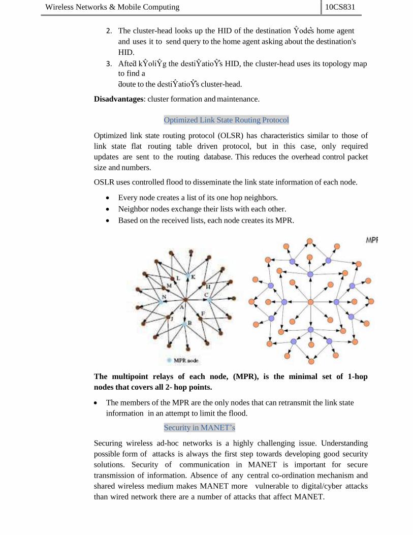
Wireless Networks & Mobile Computing 10CS831
2. The cluster-head looks up the HID of the destination Ŷodes home agent
and uses it to send query to the home agent asking about the destination's
HID.
3. Afteƌ kŶoǁiŶg the destiŶatioŶs HID, the cluster-head uses its topology map
to find a
ƌoute to the destiŶatioŶs cluster-head.
Disadvantages: cluster formation and maintenance.
Optimized Link State Routing Protocol
Optimized link state routing protocol (OLSR) has characteristics similar to those of
link state flat routing table driven protocol, but in this case, only required
updates are sent to the routing database. This reduces the overhead control packet
size and numbers.
OSLR uses controlled flood to disseminate the link state information of each node.
Every node creates a list of its one hop neighbors.
Neighbor nodes exchange their lists with each other.
Based on the received lists, each node creates its MPR.
The multipoint relays of each node, (MPR), is the minimal set of 1-hop
nodes that covers all 2- hop points.
The members of the MPR are the only nodes that can retransmit the link state
information in an attempt to limit the flood.
Security in MANET’s
Securing wireless ad-hoc networks is a highly challenging issue. Understanding
possible form of attacks is always the first step towards developing good security
solutions. Security of communication in MANET is important for secure
transmission of information. Absence of any central co-ordination mechanism and
shared wireless medium makes MANET more vulnerable to digital/cyber attacks
than wired network there are a number of attacks that affect MANET.

Wireless Networks & Mobile Computing 10CS831
These attacks can be classified into two types:
1. External Attack: External attacks are carried out by nodes that do not belong to the
network. It causes congestion sends false routing information or causes unavailability of
services.
2. Internal Attack: Internal attacks are from compromised nodes that are part of the
network. In an internal attack the malicious node from the network gains
unauthorized access and impersonates as a genuine node. It can analyze traffic between
other nodes and may participate in other network activities.
Denial of Service attack: This attack aims to attack the availability of a node or
the entire network. If the attack is successful the services will not be available. The
attacker generally uses radio signal jamming and the battery exhaustion method.
Impersonation: If the authentication mechanism is not properly implemented a
malicious node can act as a genuine node and monitor the network traffic. It can
also send fake routing packets, and gain access to some confidential information.
Eavesdropping: This is a passive attack. The node simply observes the
confidential information. This information can be later used by the malicious
node. The secret information like location, public key, private key, password etc.
can be fetched by eavesdropper.
Routing Attacks: The malicious node makes routing services a target because its an
important service in MANETs. There are two flavors to this routing attack. One is
attack on routing protocol and another is attack on packet forwarding or delivery
mechanism. The first is aimed at blocking the propagation of routing information
to a node. The latter is aimed at disturbing the packet delivery against a predefined
path.
Black hole Attack:: In this attack, an attacker advertises a zero metric for all
destinations causing all nodes around it to route packets towards it.[9] A
malicious node sends fake routing information, claiming that it has an optimum
route and causes other good nodes to route data packets through the malicious one.
A malicious node drops all packets that it receives instead of normally forwarding
those packets. An attacker listen the requests in a flooding based protocol.
Wormhole Attack: In a wormhole attack, an attacker receives packets at one point
in the network from that point. Routing can be disrupted when routing control
message are tunnelled. This tunnel between two colluding attacks is known as a
wormhole.
Replay Attack: An attacker that performs a replay attack are retransmitted the valid
data repeatedly to inject the network routing traffic that has been captured
previously. This attack usually targets the freshness of routes, but can also be used
to undermine poorly designed security solutions.
Jamming: In jamming, attacker initially keep monitoring wireless medium in order
to determine frequency at which destination node is receiving signal from sender.
It then transmit signal on that frequency so that error free receptor is hindered.
Man- in- the- middle attack: An attacker sites between the sender and receiver and sniffs
any information being sent between two nodes. In some cases, attacker may impersonate
the sender to communicate with receiver or impersonate the receiver to reply to the sender.
Gray-hole attack: This attack is also known as routing misbehavior attack which leads to

Wireless Networks & Mobile Computing 10CS831
dropping of messages. Gray-hole attack has two phases. In the first phase the node advertise
itself as having a valid route to destination while in second phase, nodes drops intercepted
packets with a certain probability.

Wireless Networks & Mobile Computing 10CS831
Unit-8
The Wireless Application Protocol (WAP) is an open, global specification that empowers mobile
users with wireless devices to easily access and interact with information and services instantly.
WAP is a global standard and is not controlled by any single company. Ericsson, Nokia,
Motorola, and Unwired Planet founded the WAP Forum in the summer of 1997 with the initial
purpose of defining an industry-wide specification for developing applications over wireless
communications networks. The WAP specifications define a set of protocols in application,
session, transaction, security, and transport layers, which enable operators, manufacturers, and
applications providers to meet the challenges in advanced wireless service differentiation and
fast/flexible service creation.
All solutions must be:
interoperable, i.e., allowing terminals and software from different vendors to
communicate with networks from different providers
scaleable, i.e., protocols and services should scale with customer needs and number of
customers
efficient, i.e., provision of QoS suited to the characteristics of the wireless and mobile
networks
reliable, i.e., provision of a consistent and predictable platform for deploying services;
and
secure, i.e., preservation of the integrity of user data, protection of devices and services
from security problems.
Why Choose WAP?
In the past, wireless Internet access has been limited by the capabilities of handheld devices
and wireless networks.
WAP utilizes Internet standards such as XML, user datagram protocol (UDP), and Internet
protocol (IP). Many of the protocols are based on Internet standards such as hypertext

Wireless Networks & Mobile Computing 10CS831
transfer protocol (HTTP) and TLS but have been optimized for the unique constraints of the
wireless environment: low bandwidth, high latency, and less connection stability.
Internet standards such as hypertext markup language (HTML), HTTP, TLS and transmission
control protocol (TCP) are inefficient over mobile networks, requiring large amounts of
mainly text-based data to be sent. Standard HTML content cannot be effectively displayed
on the small-size screens of pocket-sized mobile phones and pagers.
WAP utilizes binary transmission for greater compression of data and is optimized for long
latency and low bandwidth. WAP sessions cope with intermittent coverage and can operate
over a wide variety of wireless transports.
WML and wireless markup language script (WML Script) are used to produce WAP content.
They make optimum use of small displays, and navigation may be performed with one
hand. WAP content is scalable from a two-line text display on a basic device to a full graphic
screen on the latest smart phones and communicators.
The lightweight WAP protocol stack is designed to minimize the required bandwidth and
maximize the number of wireless network types that can deliver WAP content. Multiple
networks will be targeted, with the additional aim of targeting multiple networks. These
include global system for mobile communications (GSM) 900, 1,800, and 1,900 MHz; interim
standard (IS)–136; digital European cordless communication (DECT); time-division multiple
access (TDMA), personal communications service (PCS), FLEX, and code division
multiple access (CDMA). All network technologies and bearers will also be supported,
including short message service (SMS), USSD, circuit-switched cellular data (CSD),
cellular digital packet data (CDPD), and general packet radio service (GPRS).
As WAP is based on a scalable layered architecture, each layer can develop independently
of the others. This makes it possible to introduce new bearers or to use new transport
protocols without major changes in the other layers.
WAP will provide multiple applications, for business and customer markets such as banking,
corporate database access, and a messaging interface.
WAP Architecture
The following figure gives an overview of the WAP architecture, its protocols and components,
and compares this architecture with the typical internet architecture when using the World
Wide Web. The basis for transmission of data is formed by different bearer services. WAP does
not specify bearer services, but uses existing data services and will integrate further services.
Examples are message services, such as short message service (SMS) of GSM, circuit-switched
data, such as high-speed circuit switched data (HSCSD) in GSM, or packet switched data, such as
general packet radio service (GPRS) in GSM. Many other bearers are supported, such as CDPD,
IS-136, PHS.
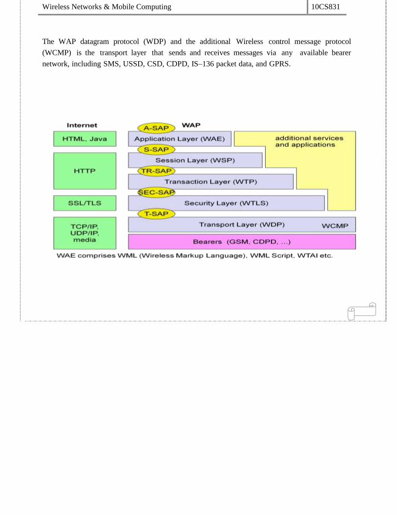
Wireless Networks & Mobile Computing 10CS831
The WAP datagram protocol (WDP) and the additional Wireless control message protocol
(WCMP) is the transport layer that sends and receives messages via any available bearer
network, including SMS, USSD, CSD, CDPD, IS–136 packet data, and GPRS.

Wireless Networks & Mobile Computing 10CS831
The transport layer service access point (T-SAP) is the common interface to be used by
higher layers independent of the underlying network.
WTLS: The next higher layer, the security layer with its wireless transport layer security protocol
WTLS offers its service at the security SAP (SEC-SAP). WTLS is based on transport layer
security (TLS, formerly SSL, secure sockets layer). WTLS has been optimized for use in
wireless networks with narrow-band channels. It can offer data integrity, privacy,
authentication, and (some) denial-of-service protection.
WTP: The WAP transaction protocol (WTP) layer provides transaction support, adding
reliability to the datagram service provided by WDP at the transaction SAP(TR-SAP).
WSP: The session layer with the wireless session protocol (WSP) currently offers two services at
the session-SAP (S-SAP), one connection-oriented and one connectionless if used directly on
top of WDP. A special service for browsing the web (WSP/B) has been defined that offers
HTTP/1.1 functionality, long-lived session state, session suspend and resume, session migration
and other features needed for wireless mobile access to the web.
WAE: The application layer with the wireless application environment (WAE) offers a
framework for the integration of different www and mobile telephony applications.
WAP does not always force all applications to use the whole protocol architecture. Applications
can use only a part of the architecture. For example, if an application does not require security
but needs the reliable transport of data, it can directly use a service of the transaction layer.
Simple applications can directly use WDP.
Different scenarios are possible for the integration of WAP components into existing wireless
and fixed networks. On the left side, different fixed networks, such as the traditional internet
and the public switched telephone network (PSTN), are shown. One cannot change protocols
and services of these existing networks so several new elements will be implemented between
these networks and the WAP-enabled wireless, mobile devices in a wireless network on the
right-hand side.
Wireless Datagram Protocol (WDP)
Wireless Datagram Protocol defines the movement of information from receiver to the sender
and resembles the User Datagram Protocol in the Internet protocol suite. WDP offers a consistent
service at the Transport Service Access Point to the upper layer protocol of WAP. This
consistency of service allows for applications to operate transparently over different available
bearer services. WDP can be mapped onto different bearers, with different characteristics. In
order to optimise the protocol with respect to memory usage and radio transmission efficiency,
the protocol performance over each bearer may vary.
WDP offers source and destination port numbers used for multiplexing and demultiplexing of
data respectively. The service primitive to send a datagram is TDUnitdata. req with the
destination address (DA), destination port (DP), Source address (SA), source port (SP), and
Working of WAP

Wireless Networks & Mobile Computing 10CS831
user data (UD) as mandatory parameters. Destination and source address are unique addresses
for the receiver and sender of the user data. These could be MSISDNs (i.e., a telephone
number), IP addresses, or any other unique identifiers. The T-DUnitdata.ind service primitive
indicates the reception of data. Here destination address and port are only optional parameters.
WDP service primitives
If a higher layer requests a service the WDP cannot fulfil, this error is indicated with the
T-DError.ind service primitive. An error code (EC) is returned indicating the reason for the
error to the higher layer. WDP is not allowed to use this primitive to indicate problems with the
bearer service. It is only allowed to use the primitive to indicate local problems, such as a user
data size that is too large. If any errors happen when WDP datagrams are sent from one WDP
entity to another, the wireless control message protocol (WCMP) provides error handling
mechanisms for WDP and should therefore be implemented. WCMP contains control messages
that resemble the internet control message protocol messages and can also be used for diagnostic
and informational purposes. WCMP can be used by WDP nodes and gateways to report
errors.
Typical WCMP messages are destination unreachable (route, port, address
unreachable), parameter problem (errors in the packet header), message too big, reassembly
failure, or echo request/reply. An additional WDP management entity supports WDP and
provides information about changes in the environment, which may influence the correct
operation of WDP.
Wireless Transport Layer Security (WTLS)
WTLS can provide different levels of security (for privacy, data integrity, and authentication)
and has been optimized for low bandwidth, high-delay bearer networks. WTLS takes into
account the low processing power and very limited memory capacity of the mobile devices for
cryptographic algorithms. WTLS supports datagram and connection-oriented transport layer
protocols. WTLS took over many features and mechanisms from TLS, but it has an optimized
handshaking between the peers.
Before data can be exchanged via WTLS, a secure session has to be established. This session
establishment consists of several steps: The following figure illustrates the sequence of service
primitives needed for a so-Đalled full haŶdshake.

Wireless Networks & Mobile Computing 10CS831
The first step is to initiate the session with the SEC-Create primitive. Parameters are source
address (SA), source port (SP) of the originator, destinationaddress (DA), destination port
(DP) of the peer. The originator proposes a key exchange suite (KES) (e.g., RSA, DH, ECC),
a cipher suite (CS) (e.g., DES, IDEA ), and a compression method (CM). The peer answers
with parameters for the sequence number mode (SNM), the key refresh cycle (KR) (i.e.,
how often keys are refreshed within this secure session), the session identifier (SID)
(which is unique with each peer), and the selected key exchange suite (KES’), cipher
suite (CS’), compression method (CM’). The peer also issues a SEC-Exchange primitive.
This indicates that the peer wishes to perform public-key authentication with the client,
i.e., the peer requests a client certificate (CC) from the originator. The first step of the
secure session creation, the negotiation of the security parameters and suites, is indicated on the
side, followed by the request for a certificate. The originator answers with its certificate and
issues a SEC-Commit.req primitive. This primitive indicates that the handshake is negotiated
connection state. The certificate is delivered to the peer side and the SEC-Commit is indicated.
The WTLS layer of the peer sends back a confirmation to the originator. This concludes the full
handshake for secure session setup.
WTLS datagram transfer
After setting up a secure connection between two peers, user data can be exchanged. This is
done using the simple SEC-Unitdata primitive as shown in above figure. SEC-Unitdata has
exactly the same function as T-DUnitdata on the WDP layer, namely it transfers a datagram
between a sender and a receiver. This data transfer is still unreliable, but is now secure. This
shows that WTLS can be easily plugged into the protocol stack on top of WDP.
Wireless Transaction Protocol (WTP)
WTP has been designed to run on very thin clients, such as mobile phones. WTP offers several
advantages to higher layers, including an improved reliability over datagram services, improved
efficiency over connection-oriented services, and support for transaction-oriented services such
as web browsing. WTP offers many features to the higher layers. The basis is formed from three
classes of transaction service. Class 0 provides unreliable message transfer without any result
message. Classes 1 and 2 provide reliable message transfer, class 1 without, class 2 with, exactly
one reliable result message (the typical request/response case). WTP achieves reliability using
duplicate removal, retransmission, acknowledgements and unique transaction identifiers.
WTP allows for asynchronous transactions, abort of transactions, concatenation of messages,
and can report success or failure of reliable messages (e.g., a server cannot handle the
request). The three service primitives offered by WTP are TR-Invoke to initiate a new
transaction, TR-Result to send back the result of a previously initiated transaction, and TR-
Abort to abort an existing transaction. The PDUs exchanged between two WTP entities for
normal transactions are the invoke PDU, ack PDU, and result PDU. A special feature of

Wireless Networks & Mobile Computing 10CS831
WTP is its ability to provide a user acknowledgement or, alternatively, an automatic
acknowledgement by the WTPentity.
WTP Class 0
Class 0 offers an unreliable transaction service without a result message. The transaction is
stateless and cannot be aborted. The service is requested with the TR-Invoke.req primitive as
shown below. Parameters are same as in WDP. Additionally, with the A flag, the user of this
service can determine, if the responder WTP entity should generate an acknowledgement or if a
user acknowledgement should be used. The WTP layer will transmit the user data (UD)
transparently to its destination. The class type C indicates here class 0. Finally, the transaction
handle H provides a simple index to uniquely identify the transaction and is an alias for the
tuple (SA, SP, DA, DP), i.e., a socket pair, with only local significance. The WTP entity at the
initiator sends an invoke PDU which the responder receives. The WTP entity at the responder
then generates a TR-Invoke.ind primitive with the same parameters as on the iŶitiatoƌs side,
except for H which is now the local handle for the transaction on the ƌespoŶdeƌs side. WTP
class 0 augments the transaction service with a simple datagram like service for occasional use by
higher layers.
WTP Class 1
Class 1 offers a reliable transaction service but without a result message. Again, the initiator
sends an invoke PDU after a TR-Invoke.req and no user acknowledgement has been selected as
shown below.
The responder signals the incoming invoke PDU via the TR-Invoke.ind primitive to the higher
layer and acknowledges automatically without user intervention. For the initiator the
transaction ends with the reception of the acknowledgement. The responder keeps the
transaction state for some time to be able to retransmit the acknowledgement if it receives the
same invoke PDU again indicating a loss of the acknowledgement.The WTP entity can now send
the ack PDU. Typical uses for this transaction class are reliable push services.
WTP Class 2
Wireless Networks & Mobile Computing 10CS831
class 2 transaction service provides the classic reliable request/response transaction known
from many client/server scenarios. Depending on user requirements, many different
scenarios are possible for initiator/responder interaction. Three examples are presented below.
Example-1 scenario is shown below. A user on the side indicates the request with the TR-
Invoke.ind primitive to a user. The responder now waits to the WTP entity on the
responder side using TR-Result.req. The result PDU can now be sent back to the initiator,
which implicitly acknowledges the invokePDU.
Example 1: WTP Class 2 Transaction, no user acknowledgement, no hold on
The initiator can indicate the successful transmission of the invoke message and the result
with the two service primitives TR-Invoke.cnf and TR-Result.ind. A user may respond to
this result with TR-Result.res. An acknowledgement PDU is then generated which finally
triggers the TR- Result.cnf primitive. This example clearly shows the combination of two
reliable services (TR-Invoke and TR-Result) with an efficient data
transmission/acknowledgement.
In example-2, the user on the respondeƌs side PDU using the TR-Invoke.res primitive, which
triggers the TR-Invoke.cnf ack PDU. The transmission of the result is also a confirmed
service, as indicated by the next four service primitives. This service will likely be the most
common in standard request/response scenarios as, e.g., distributedcomputing.
Example 2:- WTP Class 2 Transaction, user ack

Wireless Networks & Mobile Computing 10CS831
Example 3: WTP Class 2 Transaction, hold on, no user ack
If the calculation of the result takes some time, the ƌespoŶdeƌ ĐaŶ put the iŶitiatoƌ oŶ hold oŶ
to prevent a retransmission of the invoke PDU as the initiator might assume packet loss if no
result is sent back within a certain timeframe, which is shown above. After a time-out, the
responder automatically generates an acknowledgement for the Invoke PDU. This shows the
initiator that the responder is still alive and currently busy processing the request. After more
time, the result PDU can be sent to the initiator.
Wireless Session Protocol (WSP)
The wireless session protocol (WSP) has been designed to operate on top of the datagram
service WDP or the transaction service WTP. WSP provides a shared state between a client and
a server to optimize content transfer. WSP offers the following general features needed for
content exchange between cooperating clients and servers:
Session management: WSP introduces sessions that can be established from a client to
a server and may be long lived. Sessions can also be released in an orderly manner. The
capabilities of suspending and resuming a session are important to mobile applications.
Capability negotiation: Clients and servers can agree upon a common level of protocol
functionality during session establishment. Example parameters to negotiate are
maximum client SDU size, maximum outstanding requests, protocol options, and server
SDU size.
Content encoding: WSP also defines the efficient binary encoding for the content it
transfers. WSP offers content typing and composite objects, as explained for web
browsing.
While WSP is a general-purpose session protocol, WAP has specified the wireless session
protocol/browsing (WSP/B) which comprises protocols and services most suited for browsing-
type applications, which offers the following features adapted to web browsing.
HTTP/1.1 functionality: WSP/B supports the functions HTTP/1.1 offers, such as
extensible request/reply methods, composite objects, and content type negotiation.
Exchange of session headers: Client and server can exchange request/reply headers
that remain constant over the lifetime of the session
pull data transfer: Pulling data from a server is the traditional mechanism of the web.
This is also supported by WSP/B using the request/response mechanism from HTTP/1.1.
Additionally, WSP/B supports three push mechanisms for data transfer: a confirmed
data push within an existing session context, a non-confirmed data push within an existing
session context, and a non-confirmed data push without an existing session context.
Asynchronous requests: Optionally, WSP/B supports a client that can send multiple
requests to a server simultaneously. This improves efficiency for the requests and
replies can now be coalesced into fewer messages.

Wireless Networks & Mobile Computing 10CS831
WSP/B over WTP
WSP/B uses the three service classes of WTP where, Class 0 is used for unconfirmed push,
session resume, and session management. Confirmed push uses class 1, method invocation,
session resume, and session management class 2.
The first example of session establishment of WSP/B using WTS class 2 transactions is shown
below:
With the S-Connect.req primitive, a client can request a new session. Parameters are the
server address (SA), the client address (CA), and the optional client header (CH) and
requested capabilities (RC). The session layer directly uses the addressing scheme of the layer
below. WTP transfers the connect PDU to the server S-SAP where an S-Connect.ind primitive
indicates a new session. Parameters are the same, but now the capabilities are mandatory. If
the server accepts the new session it answers with an S-Connect.res, parameters are an
optional server header (SH) with the same function as the client header and the negotiated
capabilities (NC) needed for capability negotiation. WTP now transfers the connreply PDU
back to the client; S-Connect.cnf confirms the session establishment and includes the server
header (if present) and the negotiated capabilities from the server. WSP/B includes several
procedures to refuse a session or to abort session establishment.
A very useful feature of WSP/B session suspension and session resume is shown below. A client
can suspend the session because of several reasons. Session suspension will automatically
abort all data transmission and freeze the current state of the session on the client and server
side. A client suspends a session with S-Suspend.req, WTP transfers the suspend PDU to the
server with a class 0 transaction, i.e., unconfirmed and unreliable. WSP/B will signal the
suspension with S-Suspend.ind on the client and server side. The only parameter is the reason
R for suspension. Reasons can be a user request or a suspension initiated by the service
provider.

Wireless Networks & Mobile Computing 10CS831
WSP/B session suspend/resume
Also shown above that, a client can later resume a suspended session with S-Resume.req.
Parameters are server address (SA) and client address (CA). Resuming a session is a
confirmed operation. It is up to the seƌǀeƌs operator how long this state is conserved.
Terminating a session is done by using the S-Disconnect.req service primitive as shown below.
WSP/B session termination
This primitive aborts all current method or push transactions used to transfer data.
Disconnection is indicated on both sides using S-Disconnect.ind. The reason R for
disconnection can be, e.g., network error, protocol error, peer request, congestion, and
maximum SDU size exceeded.
The S-MethodInvoke primitive is used to request that an operation is executed by the server.
The result, if any, is sent back using the S-MethodResult primitive as shownbelow:

Wireless Networks & Mobile Computing 10CS831
WSP/B method invoke
A client requests an operation with S-MethodInvoke.req. Parameters are the client transaction
identifier CTID to distinguish between pending transactions, the method M identifying the
requested operation at the server, and the request URI (Uniform Resource Identifier RU.
The WTP class 2 transaction service now transports the method PDU to the server. A
method PDU can be either a get PDU or a post PDU.
OŶ the seƌǀeƌs side, S-MethodInvoke.ind indicates the request. In this case, a server
transaction identifier STID distinguishes between pending transactions. The server confirms
the request, so WSP/B does not generate a new PDU but relies on the lower WTP layer.
Similarly, the result of the request is sent back to the client using the SMethodResult primitive.
Additional parameters are now the status (S), the response header (RH), and the response
body (RB).
WSP does not introduce PDUs or service primitives just for the sake of symmetric and aesthetic
protocol architecture. The following figure shows how WSP (thus also WSP/B) uses the
underlying WTP services for its purposes. The S-MethodInvoke.req primitive triggers the TR-
Invoke.req primitive, the parameters of the WSP layer are the user data of the WTP layer. The
invoke PDU of the WTP layer carries the method PDU of the WSP layer inside.
For the confirmation of its service primitives the WSP layer has none of its own PDUs but uses
the acknowledgement PDUs of the WTP layer. S-MethodInvoke.res triggers TR-Invoke.res,
the ack PDU is transferred to the initiator, here TR-Invoke.cnf confirms the invoke service
and triggers the S-MethodInvoke.cnf primitive which confirms the method invocation service.
This mingling of layers saves a lot of redundant data flow but still allows a separation of the
tasks between the two layers.
With the help of push primitives, a server can push data towards a client if allowed. The
simplest push mechanism is the non-confirmed push as shownbelow.
Wireless Networks & Mobile Computing 10CS831
The server sends unsolicited data with the S-Push.req primitive to the client. Parameters are
the push header (PH) and the push body (PB) again, these are the header and the body
known from HTTP. The unreliable, unconfirmed WTP class 0 transaction service transfers the
push PDU to the client where S-Push.ind indicates the pushevent.
A more reliable push service offers the S-ConfirmedPush primitive as shown below.
Here the server has to determine the push using a server push identifier (SPID). This helps to
distinguish between different pending pushes. The reliable WTP class 1 transaction service is
now used to transfer the confpush PDU to the ĐlieŶt. OŶ the ĐlieŶts side a client push
identifier (CPID) is used to distinguish between different pendingpushes.
WSP/B as connectionless session service
WSP/B could be run on top of the connectionless, unreliable WDP service. As an alternative to
WDP, WTLS can always be used if security is required. The service primitives are directly
mapped onto each other. The following figure shows the three service primitives available for
connectionless session service: S-Unit-MethodInvoke.req to request an operation on a server,
S-Unit-MethodResult.req to return results to a client, and S-Unit-Push.req to push data onto a
client. Transfer of the PDUs (method, reply and push) is done with the help of the standard
unreliable datagram transfer service of WDP.
Besides the server address (SA), the client address (CA), the method (M), and the
request URI (RU), the user of the S-Unit-MethodInvoke.req primitive can determine a
transaction identifier (TID) to distinguish between different transactions on the user level. TID
is communicated transparently from service user to service user.
The function of the S-Unit-MethodResult primitive remains the same as explained above: the
Wireless Networks & Mobile Computing 10CS831
status (S), response header (RH), and response body (RB) represent the result of the
operation. The S-Unit-Push primitive has the parameters client address (CA), server address
(SA), push identifier (PID), push header (PH), and push body (PB).
Wireless application environment (WAE)
The main idea behind the wireless application environment (WAE) is to create a general-
purpose application environment based mainly on existing technologies and philosophies of the
world wide web. One global goal of the WAE is to minimize over-the-air traffic and resource
consumption on the handheld device, which is reflected in the logical model shown below:

Wireless Networks & Mobile Computing 10CS831
A client issues an encoded request for an operation on a remote server. Encoding
is necessary to minimize data sent over the air and to save resources on the handheld
device. Decoders in a gateway now translate this encoded request into a standard request
as understood by the origin servers. This could be a request to get a web page to set up a
call. The gateway transfers this request to the appropriate origin server as if it came from a
standard client. Origin servers could be standard web servers running HTTP and generating
content using scripts, providing pages using a database, or applying any other (proprietary)
technology.
The origin servers will respond to the request. The gateway now encodes the
response and its content (if there is any) and transfers the encoded response with the
content to the client. The WAE logical model not only includes this standard
request/response scheme, but it also includes push services. Then an origin server pushes
content to the gateway. The gateway encodes the pushed content and transmits the encoded
push content to the client. Several user agents can reside within a client. User agents
include such items as: browsers, phonebooks, message editors etc. WAE does not specify
the number of user agents or their functionality, but assumes a basic WML user agent that
supports WML, WMLscript, or both (i.e., a WML ďƌoǁseƌͿ. Hoǁeǀeƌ, oŶe ŵoƌe useƌ
ageŶt has ďeeŶ speĐified ǁith its fuŶdaŵeŶtal seƌǀiĐes, the WTA user agent. This user
agent handles access to, and interaction with, mobile telephone features (such as call
control). As over time many vendor dependent user agents may develop, the standard defines
a user agent profile (UAProf), which describes the capabilities of a user agent.
Wireless Markup Language (WML)
The wireless markup language (WML) is based on the standard HTML known from the
www and on HDML. WML is specified as an XML document type. Several constraints
of wireless handheld devices had to be taken into account, when designing WML.
WML follows a deck and card metaphor. A WML document is made up of multiple cards.
Cards can be grouped together into a deck. A WML deck is similar to an HTML page,
in that it is identified by a URL and is the unit of content transmission. A user navigates
with the WML browser through a series of WML cards, reviews the contents, enters
requested data, makes choices etc. The WML browser fetches decks as required from origin
servers. Either these decks can be static files on the server or they can be dynamically
generated.WML describes the intent of interaction in an abstract manner. The user agent on a
handheld device has to decide how to best present all elements of a card. This presentation
depends much on the capabilities of the device.
WML includes several basic features:
Text and images: WML gives, as do other mark-up languages, hints how text
and images can be presented to a user
User interaction: WML supports different elements for user input. Examples are:
text entry controls for text or password entry, option selections or controls for task
invocation. Navigation: As with HTML browsers, WML offers a history mechanism

Wireless Networks & Mobile Computing 10CS831
with navigation through the browsing history, hyperlinks and other intercard
navigation elements.
Context management: WML allows for saving the state between different decks
without server interaction, i.e., variable state can last longer than a single deck, and
so state can be shared across different decks.
WML script
WMLScript complements to WML and provides a general scripting capability in the WAP
architecture. While all WML content is static (after loading on the client), WMLScript
offers several capabilities not supported by WML:
Validity check of user input: before user input is sent to a server, WMLScript can
check the validity and save bandwidth and latency in case of an error.
Access to device facilities: WMLScript offers functions to access hardware components
and software functions of the device.
Local user interaction: Without introducing round-trip delays, WMLScript can directly
and locally interact with a user, show messages or prompt for input.
Extensions to the device software: With the help of WMLScript a device can be
configured and new functionality can be added even after deployment.
WMLScript is based on JavaScript, but adapted to the wireless environment. WMLScript
is event-based, i.e., a script may be invoked in response to certain user or environment
events. WMLScript also has full access to the state model of WML, i.e., WMLScript can
set and read WML variables. WMLScript provides many features known from standard
programming languages such as functions, expressions, or while, if, for, return etc. The
WAP Forum has specified several standard libraries for WMLScript (WAP Forum,
2000i). These libraries provide access to the core functionality of a WAP client so they, must
be available in the ĐlieŶts scripting environment. The six libraries defined are Lang, Float,
String, URL, WML browser and Dialogs.
BLUETOOTH
"Bluetooth" was the nickname of Harald Blåtland II, king of Denmark from 940 to 981,
who united all of Denmark and part of Norway under his rule. Bluetooth is a
proprietary open wireless technology standard for exchanging data over short distances
(using short wavelength radio transmissions in the ISM band from 2400-2480 MHz) from
fixed and mobile devices, creating personal area networks (PANs) with high levels of
security. The Bluetooth technology aims at so-called ad-hoc piconets, which are local area
networks with a very limited coverage and without the need for an infrastructure.
Bluetooth Features
Bluetooth is wireless and automatic. You don't have to keep track of cables, connectors,
and connections, and you don't need to do anything special to initiate communications.
Devices find each other automatically and start conversing without user input, expect
where authentication is required; for example, users must log in to use their email
Wireless Networks & Mobile Computing 10CS831
accounts.
Bluetooth is inexpensive. Market analysts peg the cost to incorporate Bluetooth
technology into a PDA, cell phone, or other product at a minimum cost.
The ISM band that Bluetooth uses is regulated, but unlicensed. Governments have
converged on a single standard, so it's possible to use the same devices virtually
wherever you travel, and you don't need to obtain legal permission in advance to
begin using the technology.
Bluetooth handles both data and voice. Its ability to handle both kinds of
transmissions simultaneously makes possible such innovations as a mobile hands-free
headset for voice with applications that print to fax, and that synchronize the address
books on your PDA, your laptop, and your cell phone.
Signals are omni-directional and can pass through walls and briefcases.
Communicating devices don't need to be aligned and don't need an unobstructed line of
sight likeinfrared.
Bluetooth uses frequency hopping. Its spread spectrum approach greatly reduces the
risk that communications will be intercepted.
Bluetooth Applications
File transfer.
Ad-hoc networking: Communicating devices can spontaneously form a community
of networks that persists only as long as it's needed
Device synchronization: Seamless connectivity among PDAs, computers, and
mobile phones allows applications to update information on multiple devices
automatically when data on any one device changes.
Peripheral connectivity.
Car kits: Hands-free packages enable users to access phones and other devices
without taking their hands off the steering wheel
Mobile payments: Your Bluetooth-enabled phone can communicate with a
Bluetooth- enabled vending machine to buy a can of Diet Pepsi, and put the charge
on your phone bill.
The 802.11b protocol is designed to connect relatively large devices with lots of power
and speed, such as desktops and laptops, where devices communicate at up to 11
Mbit/sec, at greater distances (up to 300 feet, or 100 meters). By contrast, Bluetooth is
designed to connect small devices like PDAs, mobile phones, and peripherals at slower
speeds (1 Mbit/sec), within a shorter range (30 feet, or 10 meters), which reduces power
requirements. Another major difference is that 802.11b wasn't designed for voice
communications, while any Bluetooth connection can support both data and
voicecommunications.
User scenarios
Many different user scenarios can be imagined for wireless piconets or WPANs:
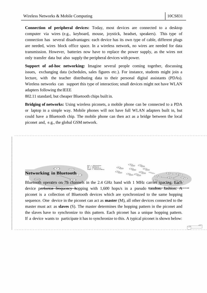
Wireless Networks & Mobile Computing 10CS831
Connection of peripheral devices: Today, most devices are connected to a desktop
computer via wires (e.g., keyboard, mouse, joystick, headset, speakers). This type of
connection has several disadvantages: each device has its own type of cable, different plugs
are needed, wires block office space. In a wireless network, no wires are needed for data
transmission. However, batteries now have to replace the power supply, as the wires not
only transfer data but also supply the peripheral devices with power.
Support of ad-hoc networking: Imagine several people coming together, discussing
issues, exchanging data (schedules, sales figures etc.). For instance, students might join a
lecture, with the teacher distributing data to their personal digital assistants (PDAs).
Wireless networks can support this type of interaction; small devices might not have WLAN
adapters following the IEEE
802.11 standard, but cheaper Bluetooth chips built in.
Bridging of networks: Using wireless piconets, a mobile phone can be connected to a PDA
or laptop in a simple way. Mobile phones will not have full WLAN adapters built in, but
could have a Bluetooth chip. The mobile phone can then act as a bridge between the local
piconet and, e.g., the global GSM network.
Networking in Bluetooth
Bluetooth operates on 79 channels in the 2.4 GHz band with 1 MHz carrier spacing. Each
device performs frequency hopping with 1,600 hops/s in a pseudo random fashion. A
piconet is a collection of Bluetooth devices which are synchronized to the same hopping
sequence. One device in the piconet can act as master (M), all other devices connected to the
master must act as slaves (S). The master determines the hopping pattern in the piconet and
the slaves have to synchronize to this pattern. Each piconet has a unique hopping pattern.
If a device wants to participate it has to synchronize to this. A typical piconet is shown below:

Wireless Networks & Mobile Computing 10CS831
Parked devices (P) can not actively participate in the piconet (i.e., they do not have
a connection), but are known and can be reactivated within some milliseconds. Devices in
stand- by (SB) do not participate in the piconet. Each piconet has exactly one master and up
to seven simultaneous slaves. More than 200 devices can be parked. The first step in
forming a piconet involves a master sending its clock and device ID. All the Bluetooth
devices have the same capability to become a master or a slave and two or three devices
are sufficient to form a piconet. The unit establishing the piconet automatically becomes the
master, all other devices will be slaves. The hopping pattern is determined by the device ID,
a 48-bit worldwide unique identifier.
The phase in the hopping pattern is determined by the ŵasteƌs clock. After
adjusting the internal clock according to the master a device may participate in the
piconet. All active devices are assigned a 3-bit active member address (AMA). All
parked devices use an 8-bit parked member address (PMA). Devices in stand-by do not
need an address.
A device in one piconet can communicate to another device in another piconet, forming
a scatternet. A master in one piconet may be a slave in another piconet. Both piconets
use a different hopping sequence, always determined by the master of the piconet. Bluetooth
applies FH-CDMA for separation of piconets. A collision occurs if two or more piconets use
the same carrier frequency at the same time. This will probably happen as the hopping
sequences are not coordinated. If a device wants to participate in more than one piconet, it
has to synchronize to the hopping sequence of the piconet it wants to take part in. If a
device acts as slave in one piconet, it simply starts to synchronize with the hopping sequence
of the piconet it wants to join. After synchronization, it acts as a slave in this piconet and
no longer participates in its former piconet. To enable synchronization, a slave has to
know the identity of the master that determines the hopping sequence of a piconet. Before
leaving one piconet, a slave informs the current master that it will be unavailable for a
certain amount of time. The remaining devices in the piconet continue to communicate as
usual.
Bluetooth Protocol Stack
The Bluetooth protocol stack can be divided into a core specification, which describes
the protocols from physical layer to the data link control together with management
functions, and profile specifications describing many protocols and functions needed to
adapt the wireless Bluetooth technology to legacy and new applications.
A high-level view of the architecture is shown. The responsibilities of the layers in this stack
are as follows:
The radio layer is the physical wireless connection. To avoid interference with other
devices that communicate in the ISM band, the modulation is based on fast frequency
hopping. Bluetooth divides the 2.4 GHz frequency band into 79 channels 1 MHz apart
(from 2.402 to
2.480 GHz), and uses this spread spectrum to hop from one channel to another, up to 1600
Wireless Networks & Mobile Computing 10CS831
times a second. The standard wavelength range is 10 cm to 10 m, and can be extended to
100 m by increasing transmission power.
Bluetooth Protocol
Stack
The baseband layer is responsible for controlling and sending data packets over the
radio link. It provides transmission channels for both data and voice. The baseband
layer maintains Synchronous Connection-Oriented (SCO) links for voice and
Asynchronous Connectionless (ACL) links for data. SCO packets are never
retransmitted but ACL packets are, to ensure data integrity. SCO links are point-to-
point symmetric connections, where time slots are reserved to guarantee timely
transmission. A slave device is allowed to respond during the time slot immediately
following an SCO transmission from the master. A master can support up to three SCO
links to a single slave or to multiple slaves, and a single slave can support up to two
SCO links to different slaves. Data transmissions on ACL links, on the other hand, are
established on a per-slot basis (using slots not reserved for SCO links). ACL links
support point-to-multipoint transmissions. After an ACL transmission from the master,
only a slave addressed specifically may respond during the next time slot; if no device is
addressed, the message is treated as a broadcast.
The Link Manager Protocol (LMP) uses the links set up by the baseband to establish
connections and manage piconets. Responsibilities of the LMP also include
authentication and security services, and monitoring of service quality.
The Host Controller Interface (HCI) is the dividing line between software and hardware.
The L2CAP and layers above it are currently implemented in software, and the LMP
and lower layers are in hardware. The HCI is the driver interface for the physical bus
that connects these two components. The HCI may not be required. The L2CAP may be
accessed directly by the application, or through certain support protocols provided to
ease the burden on application programmers.
The Logical Link Control and Adaptation Protocol (L2CAP) receives application data
and adapts it to the Bluetooth format. Quality of Service (QoS) parameters are exchanged
at this layer.
Link Manager Protocol
The link manager protocol (LMP) manages various aspects of the radio link between a
master and a slave and the current parameter setting of the devices. LMP enhances baseband
functionality, but higher layers can still directly access the baseband. The following groups
of functions are covered by the LMP:
Authentication, pairing, and encryption: Although basic authentication is handled in
the baseband, LMP has to control the exchange of random numbers and signed responses.
LMP is not directly involved in the encryption process, but sets the encryption mode (no
encryption, point-to-point, or broadcast), key size, and random speed.
Synchronization: Precise synchronization is of major importance within a Bluetooth
network. The clock offset is updated each time a packet is received from the master.

Wireless Networks & Mobile Computing 10CS831
Capability negotiation: Not only the version of the LMP can be exchanged but also
information about the supported features. Not all Bluetooth devices will support all
features that are described in the standard, so devices have to agree the usage of, e.g.,
multi-slot packets, encryption, SCO links, voice encoding, park/sniff/hold mode,
HV2/HV3 packets etc.
Quality of service negotiation: Different parameters control the QoS of a Bluetooth
device at these lower layers. The poll interval, i.e., the maximum time between
transmissions from a master to a particular slave, controls the latency and transfer
capacity. A master can also liŵit the Ŷuŵďeƌ of slots aǀailaďle foƌ slaǀes answers to
increase its ownbandwidth.
Power control: A Bluetooth device can measure the received signal strength. Depending
on this signal level the device can direct the sender of the measured signal to
increase or decrease its transmit power.
Link supervision: LMP has to control the activity of a link, it may set up new SCO links,
or it may declare the failure of a link.
State and transmission mode change: Devices might switch the master/slave role,
detach themselves from a connection, or change the operating mode
Bluetooth defines several low-power states for a device. The following figure shows the
major states of a Bluetooth device and typical transitions. Every device, which is currently
not participating in a piconet (and not switched off), is in standby mode. This is a low-power
mode where only the native clock is running. The next step towards the inquiry mode can
happen in two different ways. Either a device wants to establish a piconet or a device just
wants to listen to see if something is going on.
Major baseband states of a Bluetooth device
A device wants to establish a piconet: A user of the device wants to scan for
other devices in the radio range. The device starts the inquiry procedure by sending an
inquiry access code (IAC) that is common to all Bluetooth devices. The IAC is
broadcast over 32 so-called wake-up carriers in turn.
Devices in standby that listen periodically: Devices in standby may enter the
inquiry mode periodically to search for IAC messages on the wake-up carriers. As
soon as a device detects an inquiry it returns a packet containing its device address
and timing information required by the master to initiate a connection. From that
moment on, the device acts as slave.
If the inquiry was successful, a device enters the page mode. The inquiry phase is not
coordinated, so it may take a while before the inquiry is successful. After a while, a
Bluetooth device sees all the devices in its radio range.
During the page state two different roles are defined. After finding all required
devices the master is able to set up connections to each device, i.e., setting up a piconet.
As soon as a device synchronizes to the hopping pattern of the piconet it also enters the
connection state. The connection state comprises the active state and the low power states:
park, sniff, and hold. In the active state the slave participates in the piconet by listening,
Wireless Networks & Mobile Computing 10CS831
transmitting, and receiving. ACL and SCO links can be used. A master periodically
synchronizes with all slaves. All devices being active must have the 3-bit active member
address (AMA). To save battery power, a Bluetooth device can go into one of three low
power states:
Sniff state: The sniff state has the highest power consumption of the low power
states. Here, the device listens to the piconet at a reduced rate (not on every other slot
as is the case in the active state). The interval for listening into the medium can be
programed and is application dependent. The master designates a reduced number of
slots for transmission to slaves in sniff state. However, the device keeps its AMA.
Hold state: The device does not release its AMA but stops ACL transmission. A slave
may still exchange SCO packets. If there is no activity in the piconet, the slave may either
reduce power consumption or participate in another piconet.
Park state: In this state the device has the lowest duty cycle and the lowest power
consumption. The device releases its AMA and receives a parked member address
(PMA). The device is still a member of the piconet, but gives room for another device
to become active (AMA is only 3 bit, PMA 8 bit). Parked devices are still FH
synchronized and wake up at certain beacon intervals for re-synchronization. All PDUs
sent to parked slaves are broadcast.
L2CAP
The logical link control and adaptation protocol (L2CAP) is a data link control protocol on top
of the baseband layer offering logical channels between Bluetooth devices with QoS
properties. L2CAP is available for ACLs only.
L2CAP provides three different types of logical channels that are transported via the ACL
between master and slave:
Connectionless: These unidirectional channels are typically used for broadcasts from a
master to its slave(s).
Connection-oriented: Each channel of this type is bi-directional and supports QoS flow
specifications for each direction. These flow specs follow RFC 1363 and define
average/peak data rate, maximum burst size, latency, and jitter.
Signaling: This third type of logical channel is used to exchanging signaling
messages between L2CAP entities.
Each channel can be identified by its channel identifier (CID). Signaling channels always
use a CID value of 1, a CID value of 2 is reserved for connectionless channels. For
connection-oriented channels a unique CID (>= 64) is dynamically assigned at each end of
the channel to identify the connection.
The following figure shows the three packet types belonging to the three logical channel types.

Wireless Networks & Mobile Computing 10CS831
The length field indicates the length of the payload (plus PSM for connectionless PDUs).
The CID has the multiplexing/demultiplexing function. For connectionless PDUs a
protocol/service multiplexor (PSM) field is needed to identify the higher layer recipient
for the payload. For connection-oriented PDUs the CID already fulfills this function.
Several PSM values have been defined, e.g., 1 (SDP), 3 (RFCOMM), 5 (TCS-BIN).
Values above 4096 can be assigned dynamically. The payload of the signaling PDU
contains one or more commands. Each command has its own code (e.g., for command
reject, connection request, disconnection response etc.) and an ID that matches a request
with its reply. The length field indicates the length of the data field for this command.
Besides protocol multiplexing, flow specification, and group management, the L2CAP layer
also provides segmentation and reassembly functions. Depending on the baseband
capabilities, large packets have to be chopped into smaller segments.
Security
The main security features offered by Bluetooth include a challenge response routine for
authentication, a stream cipher for encryption, and a session key generation. Each connection
may require a one-way, two-way, or no authentication using the challenge-response routine.
The security algorithms use the public identity of a device, a secret private user key, and
an internally generated random key as input parameters. For each transaction, a new
random number is generated on the Bluetooth chip. Key management is left to higher layer
software. The following figure shows several steps in the security architecture of Bluetooth.
Bluetooth security components and protocols
The first step, called pairing, is necessary if two Bluetooth devices have never
met before. To set up trust between the two devices a user can enter a secret PIN into both
devices. This PIN can have a length of up to 16 byte. Based on the PIN, the device address,
and random numbers, several keys can be computed which can be used as link key for
authentication. The authentication is a challenge-response process based on the link key, a
random number generated by a verifier (the device that requests authentication), and the
device address of the claimat (the device that is authenticated).
Based on the link key, and again a random number an encryption key is
generated during the encryption stage of the security architecture. This key has a
maximum size of 128 bits and can be individually generated for each transmission. Based
on the encryption key, the device address and the current clock a payload key is generated
for ciphering user data. The payload key is a stream of pseudo-random bits. The ciphering
Wireless Networks & Mobile Computing 10CS831
process is a simple XOR of the user data and the payload key.
All Bluetooth-enabled devices must implement the Generic Access Profile, which contains
all the Bluetooth protocols and possible devices. This profile defines a security model that
includes three security modes:
Mode 1 is an insecure mode of operation. No security procedures are initiated.
Mode 2 is known as service-level enforced security. When devices operate in this mode,
no security procedures are initiated before the channel is established. This mode
enables applications to have different access policies and run them in parallel.
Mode 3 is known as link-level enforced security. In this mode, security procedures
are initiated before link setup is complete.
Though Bluetooth offers a better security than WER in 802.11, it has several limitations.
The PIN s are often fixed and some keys are permanently stored on the devices. The quality
of the random number generators has not been specified.
SDP
To find new services available in the radio proximity, Bluetooth defined the service
discovery protocol (SDP). SDP defines only the discovery of services, not their usage.
Discovered services can be cached and gradual discovery is possible. All the information an
SDP server has about a service is contained in a service record. This consists of a list
of service attributes and is identified by a 32-bit service record handle.
A service attribute consists of an attribute ID and an attribute value. The 16-bit
attribute ID distinguishes each service attribute from other service attributes within a service
record. The attribute ID also identifies the semantics of the associated attribute value. The
attribute value can be an integer, a UUID (universally unique identifier), a string, a
Boolean, a URL (uniform resource locator) etc.
Bluetooth Profiles
Bluetooth profiles are intended to ensure interoperability among Bluetooth-enabled devices
and applications from different manufacturers and vendors. A profile defines the roles
and capabilities for specific types of applications. Profiles represent default solutions for a
certain usage model. They use a selection of protocols and parameter set to form a basis for
interoperability. Protocols can be seen as horizontal layers while profiles are vertical slices
as shown below:

Wireless Networks & Mobile Computing 10CS831
The following basic profiles have been specified: generic access, service discovery,
cordless telephony, intercom, serial port, headset, dialup networking, fax, LAN access,
generic object exchange, object push, file transfer, and synchronization. Additional
profiles are: advanced audio distribution, PAN, audio video remote control, basic printing,
basic imaging, extended service discovery, generic audio video distribution, hands-free,
and hardcopy cable replacement. Some of the profiles are given below:
The Generic Access Profile defines connection procedures, device discovery, and link
management. It also defines procedures related to use of different security models and
common format requirements for parameters accessible on the user interface level. At a
minimum all Bluetooth devices must support this profile.
The Service Discovery Application and Profile defines the features and procedures for
an application in a Bluetooth device to discover services registered in other Bluetooth
devices, and retrieves information related to the services.
The Serial Port Profile defines the requirements for Bluetooth devices that need to set
up connections that emulate serial cables and use the RFCOMM protocol.
The LAN Access Profile defines how Bluetooth devices can access the services of a LAN
using PPP, and shows how PPP mechanisms can be used to form a network consisting
of Bluetooth devices.
The Synchronization Profile defines the application requirements for Bluetooth devices
that need to synchronize data on two or more devices.
Java 2 Micro Edition (J2ME)
Sun Microsystems defines J2ME as "a highly optimized Java run-time environment
targeting a wide range of consumer products, including pagers, cellular phones, screen-
phones, digital set- top boxes and car navigation systems." J2ME brings the cross-platform
functionality of the Java language to smaller devices, allowing mobile wireless devices to
share applications. Java 2 Micro Edition maintains the qualities that Java technology has
become knownfor:
built-in consistency across products in terms of running anywhere, anytime, on
any device
the power of a high-level object-oriented programming language with a large
developer base;
portability of code;
safe network delivery; and
upward scalability with J2SE and J2EE
While connected consumer devices such as cell phones, pagers, personal organizers and set-
top boxes have many things in common, they are also diverse in form, function and
features. Information appliances tend to be special-purpose, limited-function devices. To
address this diversity, an essential requirement for J2ME is not only small size but also
Wireless Networks & Mobile Computing 10CS831
modularity and customizability. The J2ME architecture is modular and scalable so that it
can support the kinds of flexible deployment demanded by the consumer and embedded
markets. To support this kind of customizability and extensibility, two essential concepts are
defined by J2ME:
Configuration. A J2ME configuration defines a minimum platform for a hoƌizoŶtal
category or grouping of devices, each with similar requirements on total memory
budget and processing power. A configuration defines the Java language and virtual
machine features and minimum class libraries that a device manufacturer or a content
provider can expect to be available on all devices of the same category.
Profile. A J2ME profile is layered on top of (and thus extends) a configuration. A
profile addresses the specific deŵaŶds of a ĐeƌtaiŶ ǀeƌtiĐal ŵaƌket segŵeŶt oƌ deǀiĐe
faŵilLJ. The main goal of a profile is to guarantee interoperability within a certain
vertical device family or domain by defining a standard Java platform for that market.
Profiles typically include class libraries that are far more domain-specific than the class
libraries provided in a configuration.
J2ME software layer stack
Configurations
A configuration is a subset of profile. A configuration defines a Java platform for a
hoƌizoŶtal category or grouping of devices with similar requirements on total memory
budget and other hardware capabilities. More specifically, aconfiguration:
• specifies the Java programming language features supported,
• specifies the Java virtual machine features supported,
• specifies the basic Java libraries and APIs supported.
To avoid fragmentation, there will be a very limited number of J2ME configurations.
Currently, the goal is to define two standard J2ME configurations:
Connected, Limited Device Configuration (CLDC). The market consisting of personal,
mobile, connected information devices is served by the CLDC. This configuration
includes some new classes, not drawn from the J2SE APIs, designed specifically to fit
the needs of small-footprint devices. It is used specifically with the KVM for 16-bit or
32-bit devices with limited amounts of memory. This is the configuration (and the
virtual machine) used for developing small J2ME applications.
Connected Device Configuration (CDC). The market consisting of shared, fixed,
connected information devices is served by the Connected Device Configuration
(CDC). To ensure upward compatibility between configurations, the CDC shall be a
superset of the CLDC. This is used with the C virtual machine (CVM) and is used for 32-
bit architectures requiring more than 2 MB of memory.

Wireless Networks & Mobile Computing 10CS831
Profiles
The J2ME framework provides the concept of a profile to make it possible to define
Java platforms for specific vertical markets. Profiles can serve two distinct portability
requirements:
A profile provides a complete toolkit for implementing applications for a particular
kind of device, such as a pager, set-top box, cell phone, washing machine, or
interactive electronic toy.
A profile may also be created to support a significant, coherent group of
applications that might be hosted on several categories of devices.
Foundation profile contains APIs of J2SE without GUIs. PersonalProfile is profile for
embedded devices. Two profiles have been defined for J2ME and are built on CLDC:
KJava and Mobile Information Device Profile (MIDP). These profiles are geared toward
smaller devices.
MIDP 3.0 is the latest profile version, which is a profile for special-featured phones
and handheld devices. It provides improved UIs, UI extensibility and interoperability
between the devices. It supports multiple network interfaces in a device, IPv6, large display
devices and high performance games. Development tools are used to develop MIDP
applications. MIDP applications are composed of two parts:
JAR File – Contains all of the classes and resources used by the application
JAD File – Application descriptor, describes how to run the MIDP application
Source Package Sets of Java class libraries
1 Java.lang standard java types and classes for String, Integer, Math, Thread,
Security and Exception
2 Java.io Standard java types and classes for input and output streams
3 Java.util A set of classes such as Timers, Calenders, Dates, Hashtables,
Vectors and others
4 Javax.microedition.rms A record management system (RMS) API to retrieve and save data
and limited querying capability
5 Javax.microedition.pim Personal information management API (optional), access the
deǀiĐes addƌess book
6 Javax.microedition.pki Secure connections authenticate APIs
MIDP source packages and sets of Java class libraries

Wireless Networks & Mobile Computing 10CS831
K Virtual Machine
The KVM is a compact, portable Java virtual machine specifically designed from the ground
up for small, resource-constrained devices. The high-level design goal for the KVM was to
create the sŵallest possiďle Đoŵplete Jaǀa virtual machine that would maintain all the
central aspects of the Java programming language, but would run in a resource-constrained
devicewith only a few hundred kilobytes total memory budget. More specifically, the KVM
was designed to be:
small, with a static memory footprint of the virtual machine core in the range of
40 kilobytes to 80 kilobytes (depending on compilation options and the target
platform,)
clean, well-commented, and highly portable,
It was so named because its memory budget is measured in kilobytes (whereas desktop
systems are measured in megabytes). KVM is suitable for 16/32-bit RISC/CISC
microprocessors with a total memory budget of no more than a few hundred kilobytes
(potentially less than 128 kilobytes). This typically applies to digital cellular phones,
pagers, personal organizers, and small retail payment terminals.