wireless m-bus analyzer
TRANSCRIPT
Wireless M-Bus Analyzer
User Guide Version 10
Document ID 4100401400070
IMST GmbH
Carl-Friedrich-Gauszlig-Str 2-4
47475 KAMP-LINTFORT
GERMANY
Wireless M-Bus Analyzer - User Guide Introduction
WMBus_Analyzer_UserGuide_V1_0docx Wireless Solutions V10 page i of 26
Document Information
File name WMBus_Analyzer_UserGuide_V1_0docx
Created 2013-06-10
Total pages 27
Revision History
Version Note
01 Created Initial Version
02 Draft Version Created For Review
03 Preliminary Version
04 New chapters added
10 Update to features of version 150
- Support for hysical Layer C-Mode
- Link Layer Frame Format B
- Extended Link Leyer Decoding
- Encryption Mode 9 (AES-128 GCM + GMAC)
- Decrypted Packet Export
- Integrated Software Update via HTTPs
- Customer specific Feature Extensions
Aim of this Document
This document describes the Wireless M-Bus Analyzer a Windows application which can be used in combination with the PA-iM871A radio module for capturing and analyzing of wireless M-Bus messages
Wireless M-Bus Analyzer - User Guide Introduction
WMBus_Analyzer_UserGuide_V1_0docx Wireless Solutions V10 page ii of 26
Table of Contents
1 INTRODUCTION 4
11 Overview 4
12 Installation 4
121 USB Driver 4
122 Installer 4
123 Finish Installation 5
2 GETTING STARTED 6
21 Connected PA-iM871A radio modules 6
22 Capturing wireless M-Bus Messages 7
23 Stop Capture Session 9
24 Load File 10
3 DATA VIEWS 11
31 Table View 11
32 Message View 13
33 Message Tree View amp Memory View 14
331 Packet Info 14
332 Wireless M-Bus Message Blocks 14
333 Wireless M-Bus Message Fields 15
34 Traffic Monitor 16
35 AES Key Store 17
36 Settings 18
37 Overview 19
38 Message Filter 19
39 Firmware Update 20
310 Software Update 21
311 Customer specific Feature Extensions 22
4 APPENDIX 23
41 List of Abbreviations 23
42 List of Figures 23
5 REGULATORY COMPLIANCE INFORMATION 25
Wireless M-Bus Analyzer - User Guide Introduction
WMBus_Analyzer_UserGuide_V1_0docx Wireless Solutions V10 page iii of 26
6 IMPORTANT NOTICE 26
61 Disclaimer 26
62 Contact Information 26
Wireless M-Bus Analyzer - User Guide Introduction
WMBus_Analyzer_UserGuide_V1_0docx Wireless Solutions V10 page 4 of 26
1 Introduction
11 Overview
The Wireless M-Bus Analyzer is a Windows application which can be used for capturing and analyzing of wireless M-Bus messages The application uses the PA-871A radio module for message capturing The Windows GUI offers a comfortable and easy way to configure the connected radio modules and to analyze the captured WM-Bus messages
12 Installation
The Wireless M-Bus Analyzer is shipped with one or two PA-871A radio modules which can be connected to the USB ports of a Host PC For communication over this USB interface a Virtual COM port (VCP) driver must be installed on the Host PC
121 USB Driver
The latest USBVCP driver can be downloaded from
httpwwwsilabscomproductsmcupagesusbtouartbridgevcpdriversaspx
Figure 1-1 USB Driver Installation
To verify that the USB driver installation was successful open the Windows Device Manager (ldquoStartgtControlgtPanelgtSystemgtHardwaregtDevice Managerrdquo or hit ltWINgt + ltPAUSEgt) A new USB ndash Serial Port (Silicon Labs CP210x USB to UART Bridge COMxx) entry in section Ports (COM amp LPT) should appear (see Figure 1-1)
122 Installer
The Wireless M-Bus Analyzer is based on Qt a cross-platform application and UI framework compiled with MinGW and delivered as a zip file The zip file contains a simple installer program (setupexe) which guides through the installation procedure
Note It might be necessary to install the Microsoft Visual C++ 2008 Redistributable
Package (x86) in case the application doesnt start Click the download button on the Microsoft web page Double click the vcredist_x86exe to install runtime components of Visual C++ libraries on a computer that does not have Visual C++ installed
Wireless M-Bus Analyzer - User Guide Introduction
WMBus_Analyzer_UserGuide_V1_0docx Wireless Solutions V10 page 5 of 26
123 Finish Installation
Connect one or two PA-iM871A radio modules to your PC Start WMBus_Analyzerexe and continue with the following chapter
Wireless M-Bus Analyzer - User Guide Getting Started
WMBus_Analyzer_UserGuide_V1_0docx Wireless Solutions V10 page 6 of 26
2 Getting Started
The Wireless M-Bus Analyzer can be used to capture and analyze wireless M-Bus messages Capturing of new messages requires at least one connected PA-iM871A radio module
21 Connected PA-iM871A radio modules
The Wireless M-Bus Analyzer provides an automatic PA-iM871A discovery procedure A new connected radio and its associated serial com port will be displayed in the Radios box after successful identification The tool can operate with a single radio or with two PA-iM871A modules in parallel (Dual Radio Mode)
Figure 2-1 Single Radio Mode (connected PA-iM871A at COM 87)
Figure 2-2 Dual Radio Mode (connected PA-iM871A at COM 85 + 87)
Wireless M-Bus Analyzer - User Guide Getting Started
WMBus_Analyzer_UserGuide_V1_0docx Wireless Solutions V10 page 7 of 26
22 Capturing wireless M-Bus Messages
Select New File from the main menu or toolbar to start a new capture session The following dialog will appear which allows selecting the desired Wireless M-Bus Link Mode
The following selectable Link Modes are supported
S-Mode
T-Mode
R-Mode
C-Mode
Note Meter and Other stations which are using the T-R-C- Mode are transmitting with different physical link parameters Due to this it is possible to monitor both link directions with two connected PA-iM871A modules in parallel
Figure 2-3 Select Link Mode (Dual Radio Mode Configuration for T-Mode)
Wireless M-Bus Analyzer - User Guide Getting Started
WMBus_Analyzer_UserGuide_V1_0docx Wireless Solutions V10 page 8 of 26
Finally a standard file save dialog will open to select a new file for storage purpose
Figure 2-4 File Save Dialog
The tool proposes a new filename including the current date and time information
Press Save to enable the radios and to start the capturing process
Figure 2-5 File Save Dialog
The new radio configuration will be updated in the radio box on the left side immediately
Wireless M-Bus Analyzer - User Guide Getting Started
WMBus_Analyzer_UserGuide_V1_0docx Wireless Solutions V10 page 9 of 26
23 Stop Capture Session
Choose Close File from the main menu or toolbar to finish a capture session The stored file can be opened later again for detailed message analysis
Wireless M-Bus Analyzer - User Guide Getting Started
WMBus_Analyzer_UserGuide_V1_0docx Wireless Solutions V10 page 10 of 26
24 Load File
Choose Open File or a filename from the recent file list to load an already stored capture session
Figure 2-6 Load File Dialog
A further dialog will display the load progress and amount of captured wireless M-Bus packets and stations
Wireless M-Bus Analyzer - User Guide Data Views
WMBus_Analyzer_UserGuide_V1_0docx Wireless Solutions V10 page 11 of 26
3 Data Views
This chapter describes the available data views which are provided for further analysis
Table View
Message View
Message Tree View
Message Memory View
Traffic Monitor
31 Table View
The Table View displays the captured messages in a standard table format Each line contains a single message and additional information which is generated by the tool itself (eg Date Time) The message content is displayed in hexadecimal byte format and if a message is encrypted it is stored and displayed in encrypted format The format of the message content and the table columns itself can be configured in the Settings dialog
Figure 3-1 Table View
The Table View provides the following columns
Packet - a unique packetmessage number
Date - the capture date from the PC
Time - the capture time from the PC
Port - the associated COM port radio module
Wireless M-Bus Analyzer - User Guide Data Views
WMBus_Analyzer_UserGuide_V1_0docx Wireless Solutions V10 page 12 of 26
RTC - a timestamp from the radio modules internal real time clock
RSSI - an estimated RSSI value in dBm
Station - the station type of the message sender (Meter Other P = Primary S = Secondary)
Mode - the configured link mode S T R C
Format - the received message format A or B
Status - the packet status OK CRC Error
Air Time - the packet air time (long packet preambles not included)
Length - the gross packet length including CRC Fields and Length-Field
WM-Bus Message - the received wireless M-Bus message data as hexadecimal octet stream starting with original L-Field
Note A received radio message with CRC Error will be marked red
Selecting a single message allows a more detailed analysis of the message content in the Message Tree amp Memory View (see next chapters)
Wireless M-Bus Analyzer - User Guide Data Views
WMBus_Analyzer_UserGuide_V1_0docx Wireless Solutions V10 page 13 of 26
32 Message View
The Message View displays the captured messages in a more detailed way Each message is displayed as a row of several boxes which contain the individual header fields data blocks and CRC Fields
Note A corrupted header block or data block with wrong CRC value is marked with a following red colored CRC Field
Figure 3-2 Message View
As in the Table View the message content can be displayed in several ways
Simple octet sequence
Link Layer Header + Blocks and CRCs
Link Layer Header + higher Layer Protocol Segments
Furthermore it is possible to select a single message for detailed analysis of its content The selected message will be displayed in the Message Tree amp Memory View (see next chapters)
Wireless M-Bus Analyzer - User Guide Data Views
WMBus_Analyzer_UserGuide_V1_0docx Wireless Solutions V10 page 14 of 26
33 Message Tree View amp Memory View
The Message Tree View and Memory View display a single selected message in more detail
Figure 3-3 Message Tree amp Memory View
The Tree View contains three top level sections which can be expanded to display the more information
Packet Info
WM-Bus Message Blocks
WM-Bus Message Fields
331 Packet Info
This section contains general packet information eg Date Time RSSI Air Time
332 Wireless M-Bus Message Blocks
Within this section a single message is displayed according to its wireless M-Bus Link Layer Blocks
one single Header Block + CRC Field (16 Bit)
up-to 16 Data Blocks + individual CRC Fields (16 Bit)
Each block is displayed as a row of data bytes in hexadecimal format and a separate row of CRC bytes In case of a CRC Error the complete block is displayed in red
Selecting a single row within a block of the tree structure highlights the corresponding data bytes and CRC bytes in the Memory View on the right side
Wireless M-Bus Analyzer - User Guide Data Views
WMBus_Analyzer_UserGuide_V1_0docx Wireless Solutions V10 page 15 of 26
333 Wireless M-Bus Message Fields
Error free messages with correct CRC values are also displayed according to the logical layer structure of the wireless M-Bus specification
Link Layer
Extended Link Layer
Transport Layer
Application Layer
Figure 3-4 Wireless M-Bus Message Fields
The Application Layer Fields are only displayed if the message is not encrypted or if it is possible to decrypt the message successfully The message decryption is triggered automatically when a message is selected The decryption process looks for a configured AES key in the AES Key Store (see next chapter) and decrypts the Application Layer message content according to the signalled and supported decryption algorithm On successful decryption the Application Layer Fields will be parsed and the data in the Memory View will be displayed in a decrypted state
Wireless M-Bus Analyzer - User Guide Data Views
WMBus_Analyzer_UserGuide_V1_0docx Wireless Solutions V10 page 16 of 26
34 Traffic Monitor
The Traffic Monitor View allows to inspect the amount of captured radio packets and corresponding traffic in terms of air time and duty cycle per wireless M-Bus node
Figure 3-5 Traffic Monitor View
For every discovered wireless M-Bus node the following information is presented
Man ID Device ID Version Type the device identifying bytes from the wireless M-Bus message header
Packets the number of total packets error free (good) packets and CRC error packets
Duration the time span between the start of the first and last received packet used for the average duty cycle calculation
Air Time the cumulated air time of all captured packets per node
Average Duty Cycle (avg DC) the average duty cycle based on the cumulated air time and measurement duration
Duty Cycle last Hour the duty cycle based on all captured packets within the last hour
Max Duty Cycle per Hour the max duty cycle observed in a time span of one hour
Notes
The air time calculation does not include the long preambles which are use for nodes which operate in Link Mode S1
The packet arrival time stamp is derived from the Host PCs clock and may jitter according to other application (processes) which run in parallel to this program
Wireless M-Bus Analyzer - User Guide Data Views
WMBus_Analyzer_UserGuide_V1_0docx Wireless Solutions V10 page 17 of 26
35 AES Key Store
The AES Key Store dialog can be used to configure several AES Keys for decryption purpose According to the wireless M-Bus specification the Application Layer message content might be encrypted
Important Note all captured messages are stored in encrypted format The decryption is only triggered if a message is selected in one of the provided Message Views
Figure 3-6 AES Key Store
For message decryption purpose an AES key is selected according to its wireless M-Bus Device Header Fields Man ID Device ID Version and Type
Important Note All AES Keys which are visible in the Key Store will be stored in CUsersUSERNAMEAppDataLocalIMSTWMBus_AnalyzerWMBus_Analyzerini 1)
1) USERNAME is a placeholder for your windows user name
Export Keys Import Keys The content of the AES Key store can be exported and re-imported on another PC by means of this feature
Wireless M-Bus Analyzer - User Guide Data Views
WMBus_Analyzer_UserGuide_V1_0docx Wireless Solutions V10 page 18 of 26
36 Settings
The Settings dialog provides an easy configuration mean for several options
Figure 3-7 Settings
Message Columns
The column layout which is used in the Table View and Message View can be adapted by checkingunchecking the corresponding column title
WM-Bus Message Display Format
The content of a message can be displayed in three different ways
Simple octets sequence
Detailed Link Layer Header + Blocks with CRCs
Detailed Link Layer Header + higher Protocol Layer Segments
Scroll Behaviour
The automatic scroll behaviour of Table View and Message View while capturing messages can be enabled disabled here
Wireless M-Bus Analyzer - User Guide Data Views
WMBus_Analyzer_UserGuide_V1_0docx Wireless Solutions V10 page 19 of 26
37 Overview
The Overview box gives a short overview about the number of captured packets CRC errors discovered wireless M-Bus stations and capture session time
Figure 3-8 Overview
38 Message Filter
The Message Filter box provides an easy mean to reduce the amount of displayed wireless M-Bus messages Only those messages are displayed which Link Layer Header Fields (LLA) matches to the configured and enabled (checked) filter settings
Figure 3-9 Message Filter
Note A right mouse click on a particular row in the Table View Message View or Traffic Monitor provides a simple mean to copy the address fields of the selected row directly to the filter box
Wireless M-Bus Analyzer - User Guide Data Views
WMBus_Analyzer_UserGuide_V1_0docx Wireless Solutions V10 page 20 of 26
39 Firmware Update
To enable further feature enhancements of this tool and the required PA-iM871A radio modules a firmware update support is provides The update dialog verifies the available and currently used version of the radio modules firmware and guides through the update process
Figure 3-10 Firmware Update
Wireless M-Bus Analyzer - User Guide Data Views
WMBus_Analyzer_UserGuide_V1_0docx Wireless Solutions V10 page 21 of 26
310 Software Update
The Analyzer PC application itself can be updated via HTTPs Select SoftwareUpdate from the main menu to query for a new software version
Figure 3-11 Software Update
Wireless M-Bus Analyzer - User Guide Data Views
WMBus_Analyzer_UserGuide_V1_0docx Wireless Solutions V10 page 22 of 26
311 Customer specific Feature Extensions
The new About dialog provides a list of features which are supported or not supported in the installed version
Figure 3-12 About Dialog ndash Supported Features
Wireless M-Bus Analyzer - User Guide Appendix
WMBus_Analyzer_UserGuide_V1_0docx Wireless Solutions V10 page 23 of 26
4 Appendix
41 List of Abbreviations
FW Firmware
GUI Graphical User Interface
HW Hardware
RSSI Received Signal Strength Indicator
RTC Real Time Clock
SW Software
UART Universal Asynchronous ReceiverTransmitter
42 List of Figures
Figure 1-1 USB Driver Installation 4
Figure 2-1 Single Radio Mode (connected PA-iM871A at COM 87) 6
Figure 2-2 Dual Radio Mode (connected PA-iM871A at COM 85 + 87) 6
Figure 2-3 Select Link Mode (Dual Radio Mode Configuration for T-Mode) 7
Figure 2-4 File Save Dialog 8
Figure 2-5 File Save Dialog 8
Figure 2-6 Load File Dialog 10
Figure 3-1 Table View 11
Figure 3-2 Message View 13
Figure 3-3 Message Tree amp Memory View 14
Figure 3-4 Wireless M-Bus Message Fields 15
Figure 3-5 Traffic Monitor View 16
Figure 3-6 AES Key Store 17
Figure 3-7 Settings 18
Figure 3-8 Overview 19
Figure 3-9 Message Filter 19
Figure 3-10 Firmware Update 20
Wireless M-Bus Analyzer - User Guide Appendix
WMBus_Analyzer_UserGuide_V1_0docx Wireless Solutions V10 page 24 of 26
Figure 3-11 Software Update 21
Figure 3-12 About Dialog ndash Supported Features 22
Wireless M-Bus Analyzer - User Guide Regulatory Compliance Information
WMBus_Analyzer_UserGuide_V1_0docx Wireless Solutions V10 page 25 of 26
5 Regulatory Compliance Information
The use of radio frequencies is limited by national regulations The radio module has been designed to comply with the European Unionrsquos RampTTE (Radio amp Telecommunications Terminal Equipment) directive 19995EC and can be used free of charge within the European Union Nevertheless restrictions in terms of maximum allowed RF power or duty cycle may apply
The radio module has been designed to be embedded into other products (referred as ldquofinal productsrdquo) According to the RampTTE directive the declaration of compliance with essential requirements of the RampTTE directive is within the responsibility of the manufacturer of the final product A declaration of conformity for the radio module is available from IMST GmbH on request
The applicable regulation requirements are subject to change IMST GmbH does not take any responsibility for the correctness and accuracy of the aforementioned information National laws and regulations as well as their interpretation can vary with the country In case of uncertainty it is recommended to contact either IMSTrsquos accredited Test Center or to consult the local authorities of the relevant countries
Wireless M-Bus Analyzer - User Guide Important Notice
WMBus_Analyzer_UserGuide_V1_0docx Wireless Solutions V10 page 26 of 26
6 Important Notice
61 Disclaimer
IMST GmbH points out that all information in this document is given on an ldquoas isrdquo basis No guarantee neither explicit nor implicit is given for the correctness at the time of publication IMST GmbH reserves all rights to make corrections modifications enhancements and other changes to its products and services at any time and to discontinue any product or service without prior notice It is recommended for customers to refer to the latest relevant information before placing orders and to verify that such information is current and complete All products are sold and delivered subject to ldquoGeneral Terms and Conditionsrdquo of IMST GmbH supplied at the time of order acknowledgment
IMST GmbH assumes no liability for the use of its products and does not grant any licenses for its patent rights or for any other of its intellectual property rights or third-party rights It is the customerrsquos duty to bear responsibility for compliance of systems or units in which products from IMST GmbH are integrated with applicable legal regulations Customers should provide adequate design and operating safeguards to minimize the risks associated with customer products and applications The products are not approved for use in life supporting systems or other systems whose malfunction could result in personal injury to the user Customers using the products within such applications do so at their own risk
Any reproduction of information in datasheets of IMST GmbH is permissible only if reproduction is without alteration and is accompanied by all given associated warranties conditions limitations and notices Any resale of IMST GmbH products or services with statements different from or beyond the parameters stated by IMST GmbH for that productsolution or service is not allowed and voids all express and any implied warranties The limitations on liability in favor of IMST GmbH shall also affect its employees executive personnel and bodies in the same way IMST GmbH is not responsible or liable for any such wrong statements
Copyright copy 2011 IMST GmbH
62 Contact Information
IMST GmbH
Carl-Friedrich-Gauss-Str 2-4 47475 Kamp-Lintfort Germany
T +49 2842 981 0 F +49 2842 981 299 E wimodimstde I wwwwireless-solutionsde

Wireless M-Bus Analyzer - User Guide Introduction
WMBus_Analyzer_UserGuide_V1_0docx Wireless Solutions V10 page 5 of 26
123 Finish Installation
Connect one or two PA-iM871A radio modules to your PC Start WMBus_Analyzerexe and continue with the following chapter
Wireless M-Bus Analyzer - User Guide Getting Started
WMBus_Analyzer_UserGuide_V1_0docx Wireless Solutions V10 page 6 of 26
2 Getting Started
The Wireless M-Bus Analyzer can be used to capture and analyze wireless M-Bus messages Capturing of new messages requires at least one connected PA-iM871A radio module
21 Connected PA-iM871A radio modules
The Wireless M-Bus Analyzer provides an automatic PA-iM871A discovery procedure A new connected radio and its associated serial com port will be displayed in the Radios box after successful identification The tool can operate with a single radio or with two PA-iM871A modules in parallel (Dual Radio Mode)
Figure 2-1 Single Radio Mode (connected PA-iM871A at COM 87)
Figure 2-2 Dual Radio Mode (connected PA-iM871A at COM 85 + 87)
Wireless M-Bus Analyzer - User Guide Getting Started
WMBus_Analyzer_UserGuide_V1_0docx Wireless Solutions V10 page 7 of 26
22 Capturing wireless M-Bus Messages
Select New File from the main menu or toolbar to start a new capture session The following dialog will appear which allows selecting the desired Wireless M-Bus Link Mode
The following selectable Link Modes are supported
S-Mode
T-Mode
R-Mode
C-Mode
Note Meter and Other stations which are using the T-R-C- Mode are transmitting with different physical link parameters Due to this it is possible to monitor both link directions with two connected PA-iM871A modules in parallel
Figure 2-3 Select Link Mode (Dual Radio Mode Configuration for T-Mode)
Wireless M-Bus Analyzer - User Guide Getting Started
WMBus_Analyzer_UserGuide_V1_0docx Wireless Solutions V10 page 8 of 26
Finally a standard file save dialog will open to select a new file for storage purpose
Figure 2-4 File Save Dialog
The tool proposes a new filename including the current date and time information
Press Save to enable the radios and to start the capturing process
Figure 2-5 File Save Dialog
The new radio configuration will be updated in the radio box on the left side immediately
Wireless M-Bus Analyzer - User Guide Getting Started
WMBus_Analyzer_UserGuide_V1_0docx Wireless Solutions V10 page 9 of 26
23 Stop Capture Session
Choose Close File from the main menu or toolbar to finish a capture session The stored file can be opened later again for detailed message analysis
Wireless M-Bus Analyzer - User Guide Getting Started
WMBus_Analyzer_UserGuide_V1_0docx Wireless Solutions V10 page 10 of 26
24 Load File
Choose Open File or a filename from the recent file list to load an already stored capture session
Figure 2-6 Load File Dialog
A further dialog will display the load progress and amount of captured wireless M-Bus packets and stations
Wireless M-Bus Analyzer - User Guide Data Views
WMBus_Analyzer_UserGuide_V1_0docx Wireless Solutions V10 page 11 of 26
3 Data Views
This chapter describes the available data views which are provided for further analysis
Table View
Message View
Message Tree View
Message Memory View
Traffic Monitor
31 Table View
The Table View displays the captured messages in a standard table format Each line contains a single message and additional information which is generated by the tool itself (eg Date Time) The message content is displayed in hexadecimal byte format and if a message is encrypted it is stored and displayed in encrypted format The format of the message content and the table columns itself can be configured in the Settings dialog
Figure 3-1 Table View
The Table View provides the following columns
Packet - a unique packetmessage number
Date - the capture date from the PC
Time - the capture time from the PC
Port - the associated COM port radio module
Wireless M-Bus Analyzer - User Guide Data Views
WMBus_Analyzer_UserGuide_V1_0docx Wireless Solutions V10 page 12 of 26
RTC - a timestamp from the radio modules internal real time clock
RSSI - an estimated RSSI value in dBm
Station - the station type of the message sender (Meter Other P = Primary S = Secondary)
Mode - the configured link mode S T R C
Format - the received message format A or B
Status - the packet status OK CRC Error
Air Time - the packet air time (long packet preambles not included)
Length - the gross packet length including CRC Fields and Length-Field
WM-Bus Message - the received wireless M-Bus message data as hexadecimal octet stream starting with original L-Field
Note A received radio message with CRC Error will be marked red
Selecting a single message allows a more detailed analysis of the message content in the Message Tree amp Memory View (see next chapters)
Wireless M-Bus Analyzer - User Guide Data Views
WMBus_Analyzer_UserGuide_V1_0docx Wireless Solutions V10 page 13 of 26
32 Message View
The Message View displays the captured messages in a more detailed way Each message is displayed as a row of several boxes which contain the individual header fields data blocks and CRC Fields
Note A corrupted header block or data block with wrong CRC value is marked with a following red colored CRC Field
Figure 3-2 Message View
As in the Table View the message content can be displayed in several ways
Simple octet sequence
Link Layer Header + Blocks and CRCs
Link Layer Header + higher Layer Protocol Segments
Furthermore it is possible to select a single message for detailed analysis of its content The selected message will be displayed in the Message Tree amp Memory View (see next chapters)
Wireless M-Bus Analyzer - User Guide Data Views
WMBus_Analyzer_UserGuide_V1_0docx Wireless Solutions V10 page 14 of 26
33 Message Tree View amp Memory View
The Message Tree View and Memory View display a single selected message in more detail
Figure 3-3 Message Tree amp Memory View
The Tree View contains three top level sections which can be expanded to display the more information
Packet Info
WM-Bus Message Blocks
WM-Bus Message Fields
331 Packet Info
This section contains general packet information eg Date Time RSSI Air Time
332 Wireless M-Bus Message Blocks
Within this section a single message is displayed according to its wireless M-Bus Link Layer Blocks
one single Header Block + CRC Field (16 Bit)
up-to 16 Data Blocks + individual CRC Fields (16 Bit)
Each block is displayed as a row of data bytes in hexadecimal format and a separate row of CRC bytes In case of a CRC Error the complete block is displayed in red
Selecting a single row within a block of the tree structure highlights the corresponding data bytes and CRC bytes in the Memory View on the right side
Wireless M-Bus Analyzer - User Guide Data Views
WMBus_Analyzer_UserGuide_V1_0docx Wireless Solutions V10 page 15 of 26
333 Wireless M-Bus Message Fields
Error free messages with correct CRC values are also displayed according to the logical layer structure of the wireless M-Bus specification
Link Layer
Extended Link Layer
Transport Layer
Application Layer
Figure 3-4 Wireless M-Bus Message Fields
The Application Layer Fields are only displayed if the message is not encrypted or if it is possible to decrypt the message successfully The message decryption is triggered automatically when a message is selected The decryption process looks for a configured AES key in the AES Key Store (see next chapter) and decrypts the Application Layer message content according to the signalled and supported decryption algorithm On successful decryption the Application Layer Fields will be parsed and the data in the Memory View will be displayed in a decrypted state
Wireless M-Bus Analyzer - User Guide Data Views
WMBus_Analyzer_UserGuide_V1_0docx Wireless Solutions V10 page 16 of 26
34 Traffic Monitor
The Traffic Monitor View allows to inspect the amount of captured radio packets and corresponding traffic in terms of air time and duty cycle per wireless M-Bus node
Figure 3-5 Traffic Monitor View
For every discovered wireless M-Bus node the following information is presented
Man ID Device ID Version Type the device identifying bytes from the wireless M-Bus message header
Packets the number of total packets error free (good) packets and CRC error packets
Duration the time span between the start of the first and last received packet used for the average duty cycle calculation
Air Time the cumulated air time of all captured packets per node
Average Duty Cycle (avg DC) the average duty cycle based on the cumulated air time and measurement duration
Duty Cycle last Hour the duty cycle based on all captured packets within the last hour
Max Duty Cycle per Hour the max duty cycle observed in a time span of one hour
Notes
The air time calculation does not include the long preambles which are use for nodes which operate in Link Mode S1
The packet arrival time stamp is derived from the Host PCs clock and may jitter according to other application (processes) which run in parallel to this program
Wireless M-Bus Analyzer - User Guide Data Views
WMBus_Analyzer_UserGuide_V1_0docx Wireless Solutions V10 page 17 of 26
35 AES Key Store
The AES Key Store dialog can be used to configure several AES Keys for decryption purpose According to the wireless M-Bus specification the Application Layer message content might be encrypted
Important Note all captured messages are stored in encrypted format The decryption is only triggered if a message is selected in one of the provided Message Views
Figure 3-6 AES Key Store
For message decryption purpose an AES key is selected according to its wireless M-Bus Device Header Fields Man ID Device ID Version and Type
Important Note All AES Keys which are visible in the Key Store will be stored in CUsersUSERNAMEAppDataLocalIMSTWMBus_AnalyzerWMBus_Analyzerini 1)
1) USERNAME is a placeholder for your windows user name
Export Keys Import Keys The content of the AES Key store can be exported and re-imported on another PC by means of this feature
Wireless M-Bus Analyzer - User Guide Data Views
WMBus_Analyzer_UserGuide_V1_0docx Wireless Solutions V10 page 18 of 26
36 Settings
The Settings dialog provides an easy configuration mean for several options
Figure 3-7 Settings
Message Columns
The column layout which is used in the Table View and Message View can be adapted by checkingunchecking the corresponding column title
WM-Bus Message Display Format
The content of a message can be displayed in three different ways
Simple octets sequence
Detailed Link Layer Header + Blocks with CRCs
Detailed Link Layer Header + higher Protocol Layer Segments
Scroll Behaviour
The automatic scroll behaviour of Table View and Message View while capturing messages can be enabled disabled here
Wireless M-Bus Analyzer - User Guide Data Views
WMBus_Analyzer_UserGuide_V1_0docx Wireless Solutions V10 page 19 of 26
37 Overview
The Overview box gives a short overview about the number of captured packets CRC errors discovered wireless M-Bus stations and capture session time
Figure 3-8 Overview
38 Message Filter
The Message Filter box provides an easy mean to reduce the amount of displayed wireless M-Bus messages Only those messages are displayed which Link Layer Header Fields (LLA) matches to the configured and enabled (checked) filter settings
Figure 3-9 Message Filter
Note A right mouse click on a particular row in the Table View Message View or Traffic Monitor provides a simple mean to copy the address fields of the selected row directly to the filter box
Wireless M-Bus Analyzer - User Guide Data Views
WMBus_Analyzer_UserGuide_V1_0docx Wireless Solutions V10 page 20 of 26
39 Firmware Update
To enable further feature enhancements of this tool and the required PA-iM871A radio modules a firmware update support is provides The update dialog verifies the available and currently used version of the radio modules firmware and guides through the update process
Figure 3-10 Firmware Update
Wireless M-Bus Analyzer - User Guide Data Views
WMBus_Analyzer_UserGuide_V1_0docx Wireless Solutions V10 page 21 of 26
310 Software Update
The Analyzer PC application itself can be updated via HTTPs Select SoftwareUpdate from the main menu to query for a new software version
Figure 3-11 Software Update
Wireless M-Bus Analyzer - User Guide Data Views
WMBus_Analyzer_UserGuide_V1_0docx Wireless Solutions V10 page 22 of 26
311 Customer specific Feature Extensions
The new About dialog provides a list of features which are supported or not supported in the installed version
Figure 3-12 About Dialog ndash Supported Features
Wireless M-Bus Analyzer - User Guide Appendix
WMBus_Analyzer_UserGuide_V1_0docx Wireless Solutions V10 page 23 of 26
4 Appendix
41 List of Abbreviations
FW Firmware
GUI Graphical User Interface
HW Hardware
RSSI Received Signal Strength Indicator
RTC Real Time Clock
SW Software
UART Universal Asynchronous ReceiverTransmitter
42 List of Figures
Figure 1-1 USB Driver Installation 4
Figure 2-1 Single Radio Mode (connected PA-iM871A at COM 87) 6
Figure 2-2 Dual Radio Mode (connected PA-iM871A at COM 85 + 87) 6
Figure 2-3 Select Link Mode (Dual Radio Mode Configuration for T-Mode) 7
Figure 2-4 File Save Dialog 8
Figure 2-5 File Save Dialog 8
Figure 2-6 Load File Dialog 10
Figure 3-1 Table View 11
Figure 3-2 Message View 13
Figure 3-3 Message Tree amp Memory View 14
Figure 3-4 Wireless M-Bus Message Fields 15
Figure 3-5 Traffic Monitor View 16
Figure 3-6 AES Key Store 17
Figure 3-7 Settings 18
Figure 3-8 Overview 19
Figure 3-9 Message Filter 19
Figure 3-10 Firmware Update 20
Wireless M-Bus Analyzer - User Guide Appendix
WMBus_Analyzer_UserGuide_V1_0docx Wireless Solutions V10 page 24 of 26
Figure 3-11 Software Update 21
Figure 3-12 About Dialog ndash Supported Features 22
Wireless M-Bus Analyzer - User Guide Regulatory Compliance Information
WMBus_Analyzer_UserGuide_V1_0docx Wireless Solutions V10 page 25 of 26
5 Regulatory Compliance Information
The use of radio frequencies is limited by national regulations The radio module has been designed to comply with the European Unionrsquos RampTTE (Radio amp Telecommunications Terminal Equipment) directive 19995EC and can be used free of charge within the European Union Nevertheless restrictions in terms of maximum allowed RF power or duty cycle may apply
The radio module has been designed to be embedded into other products (referred as ldquofinal productsrdquo) According to the RampTTE directive the declaration of compliance with essential requirements of the RampTTE directive is within the responsibility of the manufacturer of the final product A declaration of conformity for the radio module is available from IMST GmbH on request
The applicable regulation requirements are subject to change IMST GmbH does not take any responsibility for the correctness and accuracy of the aforementioned information National laws and regulations as well as their interpretation can vary with the country In case of uncertainty it is recommended to contact either IMSTrsquos accredited Test Center or to consult the local authorities of the relevant countries
Wireless M-Bus Analyzer - User Guide Important Notice
WMBus_Analyzer_UserGuide_V1_0docx Wireless Solutions V10 page 26 of 26
6 Important Notice
61 Disclaimer
IMST GmbH points out that all information in this document is given on an ldquoas isrdquo basis No guarantee neither explicit nor implicit is given for the correctness at the time of publication IMST GmbH reserves all rights to make corrections modifications enhancements and other changes to its products and services at any time and to discontinue any product or service without prior notice It is recommended for customers to refer to the latest relevant information before placing orders and to verify that such information is current and complete All products are sold and delivered subject to ldquoGeneral Terms and Conditionsrdquo of IMST GmbH supplied at the time of order acknowledgment
IMST GmbH assumes no liability for the use of its products and does not grant any licenses for its patent rights or for any other of its intellectual property rights or third-party rights It is the customerrsquos duty to bear responsibility for compliance of systems or units in which products from IMST GmbH are integrated with applicable legal regulations Customers should provide adequate design and operating safeguards to minimize the risks associated with customer products and applications The products are not approved for use in life supporting systems or other systems whose malfunction could result in personal injury to the user Customers using the products within such applications do so at their own risk
Any reproduction of information in datasheets of IMST GmbH is permissible only if reproduction is without alteration and is accompanied by all given associated warranties conditions limitations and notices Any resale of IMST GmbH products or services with statements different from or beyond the parameters stated by IMST GmbH for that productsolution or service is not allowed and voids all express and any implied warranties The limitations on liability in favor of IMST GmbH shall also affect its employees executive personnel and bodies in the same way IMST GmbH is not responsible or liable for any such wrong statements
Copyright copy 2011 IMST GmbH
62 Contact Information
IMST GmbH
Carl-Friedrich-Gauss-Str 2-4 47475 Kamp-Lintfort Germany
T +49 2842 981 0 F +49 2842 981 299 E wimodimstde I wwwwireless-solutionsde

Wireless M-Bus Analyzer - User Guide Getting Started
WMBus_Analyzer_UserGuide_V1_0docx Wireless Solutions V10 page 7 of 26
22 Capturing wireless M-Bus Messages
Select New File from the main menu or toolbar to start a new capture session The following dialog will appear which allows selecting the desired Wireless M-Bus Link Mode
The following selectable Link Modes are supported
S-Mode
T-Mode
R-Mode
C-Mode
Note Meter and Other stations which are using the T-R-C- Mode are transmitting with different physical link parameters Due to this it is possible to monitor both link directions with two connected PA-iM871A modules in parallel
Figure 2-3 Select Link Mode (Dual Radio Mode Configuration for T-Mode)
Wireless M-Bus Analyzer - User Guide Getting Started
WMBus_Analyzer_UserGuide_V1_0docx Wireless Solutions V10 page 8 of 26
Finally a standard file save dialog will open to select a new file for storage purpose
Figure 2-4 File Save Dialog
The tool proposes a new filename including the current date and time information
Press Save to enable the radios and to start the capturing process
Figure 2-5 File Save Dialog
The new radio configuration will be updated in the radio box on the left side immediately
Wireless M-Bus Analyzer - User Guide Getting Started
WMBus_Analyzer_UserGuide_V1_0docx Wireless Solutions V10 page 9 of 26
23 Stop Capture Session
Choose Close File from the main menu or toolbar to finish a capture session The stored file can be opened later again for detailed message analysis
Wireless M-Bus Analyzer - User Guide Getting Started
WMBus_Analyzer_UserGuide_V1_0docx Wireless Solutions V10 page 10 of 26
24 Load File
Choose Open File or a filename from the recent file list to load an already stored capture session
Figure 2-6 Load File Dialog
A further dialog will display the load progress and amount of captured wireless M-Bus packets and stations
Wireless M-Bus Analyzer - User Guide Data Views
WMBus_Analyzer_UserGuide_V1_0docx Wireless Solutions V10 page 11 of 26
3 Data Views
This chapter describes the available data views which are provided for further analysis
Table View
Message View
Message Tree View
Message Memory View
Traffic Monitor
31 Table View
The Table View displays the captured messages in a standard table format Each line contains a single message and additional information which is generated by the tool itself (eg Date Time) The message content is displayed in hexadecimal byte format and if a message is encrypted it is stored and displayed in encrypted format The format of the message content and the table columns itself can be configured in the Settings dialog
Figure 3-1 Table View
The Table View provides the following columns
Packet - a unique packetmessage number
Date - the capture date from the PC
Time - the capture time from the PC
Port - the associated COM port radio module
Wireless M-Bus Analyzer - User Guide Data Views
WMBus_Analyzer_UserGuide_V1_0docx Wireless Solutions V10 page 12 of 26
RTC - a timestamp from the radio modules internal real time clock
RSSI - an estimated RSSI value in dBm
Station - the station type of the message sender (Meter Other P = Primary S = Secondary)
Mode - the configured link mode S T R C
Format - the received message format A or B
Status - the packet status OK CRC Error
Air Time - the packet air time (long packet preambles not included)
Length - the gross packet length including CRC Fields and Length-Field
WM-Bus Message - the received wireless M-Bus message data as hexadecimal octet stream starting with original L-Field
Note A received radio message with CRC Error will be marked red
Selecting a single message allows a more detailed analysis of the message content in the Message Tree amp Memory View (see next chapters)
Wireless M-Bus Analyzer - User Guide Data Views
WMBus_Analyzer_UserGuide_V1_0docx Wireless Solutions V10 page 13 of 26
32 Message View
The Message View displays the captured messages in a more detailed way Each message is displayed as a row of several boxes which contain the individual header fields data blocks and CRC Fields
Note A corrupted header block or data block with wrong CRC value is marked with a following red colored CRC Field
Figure 3-2 Message View
As in the Table View the message content can be displayed in several ways
Simple octet sequence
Link Layer Header + Blocks and CRCs
Link Layer Header + higher Layer Protocol Segments
Furthermore it is possible to select a single message for detailed analysis of its content The selected message will be displayed in the Message Tree amp Memory View (see next chapters)
Wireless M-Bus Analyzer - User Guide Data Views
WMBus_Analyzer_UserGuide_V1_0docx Wireless Solutions V10 page 14 of 26
33 Message Tree View amp Memory View
The Message Tree View and Memory View display a single selected message in more detail
Figure 3-3 Message Tree amp Memory View
The Tree View contains three top level sections which can be expanded to display the more information
Packet Info
WM-Bus Message Blocks
WM-Bus Message Fields
331 Packet Info
This section contains general packet information eg Date Time RSSI Air Time
332 Wireless M-Bus Message Blocks
Within this section a single message is displayed according to its wireless M-Bus Link Layer Blocks
one single Header Block + CRC Field (16 Bit)
up-to 16 Data Blocks + individual CRC Fields (16 Bit)
Each block is displayed as a row of data bytes in hexadecimal format and a separate row of CRC bytes In case of a CRC Error the complete block is displayed in red
Selecting a single row within a block of the tree structure highlights the corresponding data bytes and CRC bytes in the Memory View on the right side
Wireless M-Bus Analyzer - User Guide Data Views
WMBus_Analyzer_UserGuide_V1_0docx Wireless Solutions V10 page 15 of 26
333 Wireless M-Bus Message Fields
Error free messages with correct CRC values are also displayed according to the logical layer structure of the wireless M-Bus specification
Link Layer
Extended Link Layer
Transport Layer
Application Layer
Figure 3-4 Wireless M-Bus Message Fields
The Application Layer Fields are only displayed if the message is not encrypted or if it is possible to decrypt the message successfully The message decryption is triggered automatically when a message is selected The decryption process looks for a configured AES key in the AES Key Store (see next chapter) and decrypts the Application Layer message content according to the signalled and supported decryption algorithm On successful decryption the Application Layer Fields will be parsed and the data in the Memory View will be displayed in a decrypted state
Wireless M-Bus Analyzer - User Guide Data Views
WMBus_Analyzer_UserGuide_V1_0docx Wireless Solutions V10 page 16 of 26
34 Traffic Monitor
The Traffic Monitor View allows to inspect the amount of captured radio packets and corresponding traffic in terms of air time and duty cycle per wireless M-Bus node
Figure 3-5 Traffic Monitor View
For every discovered wireless M-Bus node the following information is presented
Man ID Device ID Version Type the device identifying bytes from the wireless M-Bus message header
Packets the number of total packets error free (good) packets and CRC error packets
Duration the time span between the start of the first and last received packet used for the average duty cycle calculation
Air Time the cumulated air time of all captured packets per node
Average Duty Cycle (avg DC) the average duty cycle based on the cumulated air time and measurement duration
Duty Cycle last Hour the duty cycle based on all captured packets within the last hour
Max Duty Cycle per Hour the max duty cycle observed in a time span of one hour
Notes
The air time calculation does not include the long preambles which are use for nodes which operate in Link Mode S1
The packet arrival time stamp is derived from the Host PCs clock and may jitter according to other application (processes) which run in parallel to this program
Wireless M-Bus Analyzer - User Guide Data Views
WMBus_Analyzer_UserGuide_V1_0docx Wireless Solutions V10 page 17 of 26
35 AES Key Store
The AES Key Store dialog can be used to configure several AES Keys for decryption purpose According to the wireless M-Bus specification the Application Layer message content might be encrypted
Important Note all captured messages are stored in encrypted format The decryption is only triggered if a message is selected in one of the provided Message Views
Figure 3-6 AES Key Store
For message decryption purpose an AES key is selected according to its wireless M-Bus Device Header Fields Man ID Device ID Version and Type
Important Note All AES Keys which are visible in the Key Store will be stored in CUsersUSERNAMEAppDataLocalIMSTWMBus_AnalyzerWMBus_Analyzerini 1)
1) USERNAME is a placeholder for your windows user name
Export Keys Import Keys The content of the AES Key store can be exported and re-imported on another PC by means of this feature
Wireless M-Bus Analyzer - User Guide Data Views
WMBus_Analyzer_UserGuide_V1_0docx Wireless Solutions V10 page 18 of 26
36 Settings
The Settings dialog provides an easy configuration mean for several options
Figure 3-7 Settings
Message Columns
The column layout which is used in the Table View and Message View can be adapted by checkingunchecking the corresponding column title
WM-Bus Message Display Format
The content of a message can be displayed in three different ways
Simple octets sequence
Detailed Link Layer Header + Blocks with CRCs
Detailed Link Layer Header + higher Protocol Layer Segments
Scroll Behaviour
The automatic scroll behaviour of Table View and Message View while capturing messages can be enabled disabled here
Wireless M-Bus Analyzer - User Guide Data Views
WMBus_Analyzer_UserGuide_V1_0docx Wireless Solutions V10 page 19 of 26
37 Overview
The Overview box gives a short overview about the number of captured packets CRC errors discovered wireless M-Bus stations and capture session time
Figure 3-8 Overview
38 Message Filter
The Message Filter box provides an easy mean to reduce the amount of displayed wireless M-Bus messages Only those messages are displayed which Link Layer Header Fields (LLA) matches to the configured and enabled (checked) filter settings
Figure 3-9 Message Filter
Note A right mouse click on a particular row in the Table View Message View or Traffic Monitor provides a simple mean to copy the address fields of the selected row directly to the filter box
Wireless M-Bus Analyzer - User Guide Data Views
WMBus_Analyzer_UserGuide_V1_0docx Wireless Solutions V10 page 20 of 26
39 Firmware Update
To enable further feature enhancements of this tool and the required PA-iM871A radio modules a firmware update support is provides The update dialog verifies the available and currently used version of the radio modules firmware and guides through the update process
Figure 3-10 Firmware Update
Wireless M-Bus Analyzer - User Guide Data Views
WMBus_Analyzer_UserGuide_V1_0docx Wireless Solutions V10 page 21 of 26
310 Software Update
The Analyzer PC application itself can be updated via HTTPs Select SoftwareUpdate from the main menu to query for a new software version
Figure 3-11 Software Update
Wireless M-Bus Analyzer - User Guide Data Views
WMBus_Analyzer_UserGuide_V1_0docx Wireless Solutions V10 page 22 of 26
311 Customer specific Feature Extensions
The new About dialog provides a list of features which are supported or not supported in the installed version
Figure 3-12 About Dialog ndash Supported Features
Wireless M-Bus Analyzer - User Guide Appendix
WMBus_Analyzer_UserGuide_V1_0docx Wireless Solutions V10 page 23 of 26
4 Appendix
41 List of Abbreviations
FW Firmware
GUI Graphical User Interface
HW Hardware
RSSI Received Signal Strength Indicator
RTC Real Time Clock
SW Software
UART Universal Asynchronous ReceiverTransmitter
42 List of Figures
Figure 1-1 USB Driver Installation 4
Figure 2-1 Single Radio Mode (connected PA-iM871A at COM 87) 6
Figure 2-2 Dual Radio Mode (connected PA-iM871A at COM 85 + 87) 6
Figure 2-3 Select Link Mode (Dual Radio Mode Configuration for T-Mode) 7
Figure 2-4 File Save Dialog 8
Figure 2-5 File Save Dialog 8
Figure 2-6 Load File Dialog 10
Figure 3-1 Table View 11
Figure 3-2 Message View 13
Figure 3-3 Message Tree amp Memory View 14
Figure 3-4 Wireless M-Bus Message Fields 15
Figure 3-5 Traffic Monitor View 16
Figure 3-6 AES Key Store 17
Figure 3-7 Settings 18
Figure 3-8 Overview 19
Figure 3-9 Message Filter 19
Figure 3-10 Firmware Update 20
Wireless M-Bus Analyzer - User Guide Appendix
WMBus_Analyzer_UserGuide_V1_0docx Wireless Solutions V10 page 24 of 26
Figure 3-11 Software Update 21
Figure 3-12 About Dialog ndash Supported Features 22
Wireless M-Bus Analyzer - User Guide Regulatory Compliance Information
WMBus_Analyzer_UserGuide_V1_0docx Wireless Solutions V10 page 25 of 26
5 Regulatory Compliance Information
The use of radio frequencies is limited by national regulations The radio module has been designed to comply with the European Unionrsquos RampTTE (Radio amp Telecommunications Terminal Equipment) directive 19995EC and can be used free of charge within the European Union Nevertheless restrictions in terms of maximum allowed RF power or duty cycle may apply
The radio module has been designed to be embedded into other products (referred as ldquofinal productsrdquo) According to the RampTTE directive the declaration of compliance with essential requirements of the RampTTE directive is within the responsibility of the manufacturer of the final product A declaration of conformity for the radio module is available from IMST GmbH on request
The applicable regulation requirements are subject to change IMST GmbH does not take any responsibility for the correctness and accuracy of the aforementioned information National laws and regulations as well as their interpretation can vary with the country In case of uncertainty it is recommended to contact either IMSTrsquos accredited Test Center or to consult the local authorities of the relevant countries
Wireless M-Bus Analyzer - User Guide Important Notice
WMBus_Analyzer_UserGuide_V1_0docx Wireless Solutions V10 page 26 of 26
6 Important Notice
61 Disclaimer
IMST GmbH points out that all information in this document is given on an ldquoas isrdquo basis No guarantee neither explicit nor implicit is given for the correctness at the time of publication IMST GmbH reserves all rights to make corrections modifications enhancements and other changes to its products and services at any time and to discontinue any product or service without prior notice It is recommended for customers to refer to the latest relevant information before placing orders and to verify that such information is current and complete All products are sold and delivered subject to ldquoGeneral Terms and Conditionsrdquo of IMST GmbH supplied at the time of order acknowledgment
IMST GmbH assumes no liability for the use of its products and does not grant any licenses for its patent rights or for any other of its intellectual property rights or third-party rights It is the customerrsquos duty to bear responsibility for compliance of systems or units in which products from IMST GmbH are integrated with applicable legal regulations Customers should provide adequate design and operating safeguards to minimize the risks associated with customer products and applications The products are not approved for use in life supporting systems or other systems whose malfunction could result in personal injury to the user Customers using the products within such applications do so at their own risk
Any reproduction of information in datasheets of IMST GmbH is permissible only if reproduction is without alteration and is accompanied by all given associated warranties conditions limitations and notices Any resale of IMST GmbH products or services with statements different from or beyond the parameters stated by IMST GmbH for that productsolution or service is not allowed and voids all express and any implied warranties The limitations on liability in favor of IMST GmbH shall also affect its employees executive personnel and bodies in the same way IMST GmbH is not responsible or liable for any such wrong statements
Copyright copy 2011 IMST GmbH
62 Contact Information
IMST GmbH
Carl-Friedrich-Gauss-Str 2-4 47475 Kamp-Lintfort Germany
T +49 2842 981 0 F +49 2842 981 299 E wimodimstde I wwwwireless-solutionsde
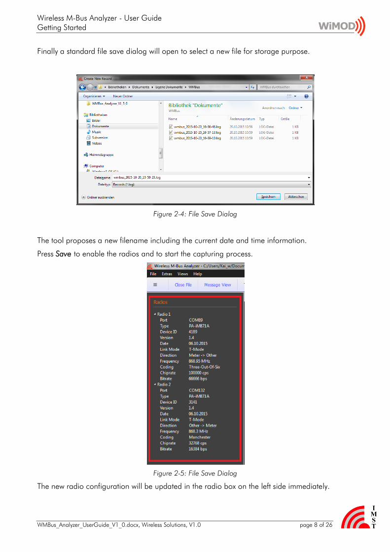
Wireless M-Bus Analyzer - User Guide Getting Started
WMBus_Analyzer_UserGuide_V1_0docx Wireless Solutions V10 page 8 of 26
Finally a standard file save dialog will open to select a new file for storage purpose
Figure 2-4 File Save Dialog
The tool proposes a new filename including the current date and time information
Press Save to enable the radios and to start the capturing process
Figure 2-5 File Save Dialog
The new radio configuration will be updated in the radio box on the left side immediately
Wireless M-Bus Analyzer - User Guide Getting Started
WMBus_Analyzer_UserGuide_V1_0docx Wireless Solutions V10 page 9 of 26
23 Stop Capture Session
Choose Close File from the main menu or toolbar to finish a capture session The stored file can be opened later again for detailed message analysis
Wireless M-Bus Analyzer - User Guide Getting Started
WMBus_Analyzer_UserGuide_V1_0docx Wireless Solutions V10 page 10 of 26
24 Load File
Choose Open File or a filename from the recent file list to load an already stored capture session
Figure 2-6 Load File Dialog
A further dialog will display the load progress and amount of captured wireless M-Bus packets and stations
Wireless M-Bus Analyzer - User Guide Data Views
WMBus_Analyzer_UserGuide_V1_0docx Wireless Solutions V10 page 11 of 26
3 Data Views
This chapter describes the available data views which are provided for further analysis
Table View
Message View
Message Tree View
Message Memory View
Traffic Monitor
31 Table View
The Table View displays the captured messages in a standard table format Each line contains a single message and additional information which is generated by the tool itself (eg Date Time) The message content is displayed in hexadecimal byte format and if a message is encrypted it is stored and displayed in encrypted format The format of the message content and the table columns itself can be configured in the Settings dialog
Figure 3-1 Table View
The Table View provides the following columns
Packet - a unique packetmessage number
Date - the capture date from the PC
Time - the capture time from the PC
Port - the associated COM port radio module
Wireless M-Bus Analyzer - User Guide Data Views
WMBus_Analyzer_UserGuide_V1_0docx Wireless Solutions V10 page 12 of 26
RTC - a timestamp from the radio modules internal real time clock
RSSI - an estimated RSSI value in dBm
Station - the station type of the message sender (Meter Other P = Primary S = Secondary)
Mode - the configured link mode S T R C
Format - the received message format A or B
Status - the packet status OK CRC Error
Air Time - the packet air time (long packet preambles not included)
Length - the gross packet length including CRC Fields and Length-Field
WM-Bus Message - the received wireless M-Bus message data as hexadecimal octet stream starting with original L-Field
Note A received radio message with CRC Error will be marked red
Selecting a single message allows a more detailed analysis of the message content in the Message Tree amp Memory View (see next chapters)
Wireless M-Bus Analyzer - User Guide Data Views
WMBus_Analyzer_UserGuide_V1_0docx Wireless Solutions V10 page 13 of 26
32 Message View
The Message View displays the captured messages in a more detailed way Each message is displayed as a row of several boxes which contain the individual header fields data blocks and CRC Fields
Note A corrupted header block or data block with wrong CRC value is marked with a following red colored CRC Field
Figure 3-2 Message View
As in the Table View the message content can be displayed in several ways
Simple octet sequence
Link Layer Header + Blocks and CRCs
Link Layer Header + higher Layer Protocol Segments
Furthermore it is possible to select a single message for detailed analysis of its content The selected message will be displayed in the Message Tree amp Memory View (see next chapters)
Wireless M-Bus Analyzer - User Guide Data Views
WMBus_Analyzer_UserGuide_V1_0docx Wireless Solutions V10 page 14 of 26
33 Message Tree View amp Memory View
The Message Tree View and Memory View display a single selected message in more detail
Figure 3-3 Message Tree amp Memory View
The Tree View contains three top level sections which can be expanded to display the more information
Packet Info
WM-Bus Message Blocks
WM-Bus Message Fields
331 Packet Info
This section contains general packet information eg Date Time RSSI Air Time
332 Wireless M-Bus Message Blocks
Within this section a single message is displayed according to its wireless M-Bus Link Layer Blocks
one single Header Block + CRC Field (16 Bit)
up-to 16 Data Blocks + individual CRC Fields (16 Bit)
Each block is displayed as a row of data bytes in hexadecimal format and a separate row of CRC bytes In case of a CRC Error the complete block is displayed in red
Selecting a single row within a block of the tree structure highlights the corresponding data bytes and CRC bytes in the Memory View on the right side
Wireless M-Bus Analyzer - User Guide Data Views
WMBus_Analyzer_UserGuide_V1_0docx Wireless Solutions V10 page 15 of 26
333 Wireless M-Bus Message Fields
Error free messages with correct CRC values are also displayed according to the logical layer structure of the wireless M-Bus specification
Link Layer
Extended Link Layer
Transport Layer
Application Layer
Figure 3-4 Wireless M-Bus Message Fields
The Application Layer Fields are only displayed if the message is not encrypted or if it is possible to decrypt the message successfully The message decryption is triggered automatically when a message is selected The decryption process looks for a configured AES key in the AES Key Store (see next chapter) and decrypts the Application Layer message content according to the signalled and supported decryption algorithm On successful decryption the Application Layer Fields will be parsed and the data in the Memory View will be displayed in a decrypted state
Wireless M-Bus Analyzer - User Guide Data Views
WMBus_Analyzer_UserGuide_V1_0docx Wireless Solutions V10 page 16 of 26
34 Traffic Monitor
The Traffic Monitor View allows to inspect the amount of captured radio packets and corresponding traffic in terms of air time and duty cycle per wireless M-Bus node
Figure 3-5 Traffic Monitor View
For every discovered wireless M-Bus node the following information is presented
Man ID Device ID Version Type the device identifying bytes from the wireless M-Bus message header
Packets the number of total packets error free (good) packets and CRC error packets
Duration the time span between the start of the first and last received packet used for the average duty cycle calculation
Air Time the cumulated air time of all captured packets per node
Average Duty Cycle (avg DC) the average duty cycle based on the cumulated air time and measurement duration
Duty Cycle last Hour the duty cycle based on all captured packets within the last hour
Max Duty Cycle per Hour the max duty cycle observed in a time span of one hour
Notes
The air time calculation does not include the long preambles which are use for nodes which operate in Link Mode S1
The packet arrival time stamp is derived from the Host PCs clock and may jitter according to other application (processes) which run in parallel to this program
Wireless M-Bus Analyzer - User Guide Data Views
WMBus_Analyzer_UserGuide_V1_0docx Wireless Solutions V10 page 17 of 26
35 AES Key Store
The AES Key Store dialog can be used to configure several AES Keys for decryption purpose According to the wireless M-Bus specification the Application Layer message content might be encrypted
Important Note all captured messages are stored in encrypted format The decryption is only triggered if a message is selected in one of the provided Message Views
Figure 3-6 AES Key Store
For message decryption purpose an AES key is selected according to its wireless M-Bus Device Header Fields Man ID Device ID Version and Type
Important Note All AES Keys which are visible in the Key Store will be stored in CUsersUSERNAMEAppDataLocalIMSTWMBus_AnalyzerWMBus_Analyzerini 1)
1) USERNAME is a placeholder for your windows user name
Export Keys Import Keys The content of the AES Key store can be exported and re-imported on another PC by means of this feature
Wireless M-Bus Analyzer - User Guide Data Views
WMBus_Analyzer_UserGuide_V1_0docx Wireless Solutions V10 page 18 of 26
36 Settings
The Settings dialog provides an easy configuration mean for several options
Figure 3-7 Settings
Message Columns
The column layout which is used in the Table View and Message View can be adapted by checkingunchecking the corresponding column title
WM-Bus Message Display Format
The content of a message can be displayed in three different ways
Simple octets sequence
Detailed Link Layer Header + Blocks with CRCs
Detailed Link Layer Header + higher Protocol Layer Segments
Scroll Behaviour
The automatic scroll behaviour of Table View and Message View while capturing messages can be enabled disabled here
Wireless M-Bus Analyzer - User Guide Data Views
WMBus_Analyzer_UserGuide_V1_0docx Wireless Solutions V10 page 19 of 26
37 Overview
The Overview box gives a short overview about the number of captured packets CRC errors discovered wireless M-Bus stations and capture session time
Figure 3-8 Overview
38 Message Filter
The Message Filter box provides an easy mean to reduce the amount of displayed wireless M-Bus messages Only those messages are displayed which Link Layer Header Fields (LLA) matches to the configured and enabled (checked) filter settings
Figure 3-9 Message Filter
Note A right mouse click on a particular row in the Table View Message View or Traffic Monitor provides a simple mean to copy the address fields of the selected row directly to the filter box
Wireless M-Bus Analyzer - User Guide Data Views
WMBus_Analyzer_UserGuide_V1_0docx Wireless Solutions V10 page 20 of 26
39 Firmware Update
To enable further feature enhancements of this tool and the required PA-iM871A radio modules a firmware update support is provides The update dialog verifies the available and currently used version of the radio modules firmware and guides through the update process
Figure 3-10 Firmware Update
Wireless M-Bus Analyzer - User Guide Data Views
WMBus_Analyzer_UserGuide_V1_0docx Wireless Solutions V10 page 21 of 26
310 Software Update
The Analyzer PC application itself can be updated via HTTPs Select SoftwareUpdate from the main menu to query for a new software version
Figure 3-11 Software Update
Wireless M-Bus Analyzer - User Guide Data Views
WMBus_Analyzer_UserGuide_V1_0docx Wireless Solutions V10 page 22 of 26
311 Customer specific Feature Extensions
The new About dialog provides a list of features which are supported or not supported in the installed version
Figure 3-12 About Dialog ndash Supported Features
Wireless M-Bus Analyzer - User Guide Appendix
WMBus_Analyzer_UserGuide_V1_0docx Wireless Solutions V10 page 23 of 26
4 Appendix
41 List of Abbreviations
FW Firmware
GUI Graphical User Interface
HW Hardware
RSSI Received Signal Strength Indicator
RTC Real Time Clock
SW Software
UART Universal Asynchronous ReceiverTransmitter
42 List of Figures
Figure 1-1 USB Driver Installation 4
Figure 2-1 Single Radio Mode (connected PA-iM871A at COM 87) 6
Figure 2-2 Dual Radio Mode (connected PA-iM871A at COM 85 + 87) 6
Figure 2-3 Select Link Mode (Dual Radio Mode Configuration for T-Mode) 7
Figure 2-4 File Save Dialog 8
Figure 2-5 File Save Dialog 8
Figure 2-6 Load File Dialog 10
Figure 3-1 Table View 11
Figure 3-2 Message View 13
Figure 3-3 Message Tree amp Memory View 14
Figure 3-4 Wireless M-Bus Message Fields 15
Figure 3-5 Traffic Monitor View 16
Figure 3-6 AES Key Store 17
Figure 3-7 Settings 18
Figure 3-8 Overview 19
Figure 3-9 Message Filter 19
Figure 3-10 Firmware Update 20
Wireless M-Bus Analyzer - User Guide Appendix
WMBus_Analyzer_UserGuide_V1_0docx Wireless Solutions V10 page 24 of 26
Figure 3-11 Software Update 21
Figure 3-12 About Dialog ndash Supported Features 22
Wireless M-Bus Analyzer - User Guide Regulatory Compliance Information
WMBus_Analyzer_UserGuide_V1_0docx Wireless Solutions V10 page 25 of 26
5 Regulatory Compliance Information
The use of radio frequencies is limited by national regulations The radio module has been designed to comply with the European Unionrsquos RampTTE (Radio amp Telecommunications Terminal Equipment) directive 19995EC and can be used free of charge within the European Union Nevertheless restrictions in terms of maximum allowed RF power or duty cycle may apply
The radio module has been designed to be embedded into other products (referred as ldquofinal productsrdquo) According to the RampTTE directive the declaration of compliance with essential requirements of the RampTTE directive is within the responsibility of the manufacturer of the final product A declaration of conformity for the radio module is available from IMST GmbH on request
The applicable regulation requirements are subject to change IMST GmbH does not take any responsibility for the correctness and accuracy of the aforementioned information National laws and regulations as well as their interpretation can vary with the country In case of uncertainty it is recommended to contact either IMSTrsquos accredited Test Center or to consult the local authorities of the relevant countries
Wireless M-Bus Analyzer - User Guide Important Notice
WMBus_Analyzer_UserGuide_V1_0docx Wireless Solutions V10 page 26 of 26
6 Important Notice
61 Disclaimer
IMST GmbH points out that all information in this document is given on an ldquoas isrdquo basis No guarantee neither explicit nor implicit is given for the correctness at the time of publication IMST GmbH reserves all rights to make corrections modifications enhancements and other changes to its products and services at any time and to discontinue any product or service without prior notice It is recommended for customers to refer to the latest relevant information before placing orders and to verify that such information is current and complete All products are sold and delivered subject to ldquoGeneral Terms and Conditionsrdquo of IMST GmbH supplied at the time of order acknowledgment
IMST GmbH assumes no liability for the use of its products and does not grant any licenses for its patent rights or for any other of its intellectual property rights or third-party rights It is the customerrsquos duty to bear responsibility for compliance of systems or units in which products from IMST GmbH are integrated with applicable legal regulations Customers should provide adequate design and operating safeguards to minimize the risks associated with customer products and applications The products are not approved for use in life supporting systems or other systems whose malfunction could result in personal injury to the user Customers using the products within such applications do so at their own risk
Any reproduction of information in datasheets of IMST GmbH is permissible only if reproduction is without alteration and is accompanied by all given associated warranties conditions limitations and notices Any resale of IMST GmbH products or services with statements different from or beyond the parameters stated by IMST GmbH for that productsolution or service is not allowed and voids all express and any implied warranties The limitations on liability in favor of IMST GmbH shall also affect its employees executive personnel and bodies in the same way IMST GmbH is not responsible or liable for any such wrong statements
Copyright copy 2011 IMST GmbH
62 Contact Information
IMST GmbH
Carl-Friedrich-Gauss-Str 2-4 47475 Kamp-Lintfort Germany
T +49 2842 981 0 F +49 2842 981 299 E wimodimstde I wwwwireless-solutionsde
Wireless M-Bus Analyzer - User Guide Getting Started
WMBus_Analyzer_UserGuide_V1_0docx Wireless Solutions V10 page 9 of 26
23 Stop Capture Session
Choose Close File from the main menu or toolbar to finish a capture session The stored file can be opened later again for detailed message analysis
Wireless M-Bus Analyzer - User Guide Getting Started
WMBus_Analyzer_UserGuide_V1_0docx Wireless Solutions V10 page 10 of 26
24 Load File
Choose Open File or a filename from the recent file list to load an already stored capture session
Figure 2-6 Load File Dialog
A further dialog will display the load progress and amount of captured wireless M-Bus packets and stations
Wireless M-Bus Analyzer - User Guide Data Views
WMBus_Analyzer_UserGuide_V1_0docx Wireless Solutions V10 page 11 of 26
3 Data Views
This chapter describes the available data views which are provided for further analysis
Table View
Message View
Message Tree View
Message Memory View
Traffic Monitor
31 Table View
The Table View displays the captured messages in a standard table format Each line contains a single message and additional information which is generated by the tool itself (eg Date Time) The message content is displayed in hexadecimal byte format and if a message is encrypted it is stored and displayed in encrypted format The format of the message content and the table columns itself can be configured in the Settings dialog
Figure 3-1 Table View
The Table View provides the following columns
Packet - a unique packetmessage number
Date - the capture date from the PC
Time - the capture time from the PC
Port - the associated COM port radio module
Wireless M-Bus Analyzer - User Guide Data Views
WMBus_Analyzer_UserGuide_V1_0docx Wireless Solutions V10 page 12 of 26
RTC - a timestamp from the radio modules internal real time clock
RSSI - an estimated RSSI value in dBm
Station - the station type of the message sender (Meter Other P = Primary S = Secondary)
Mode - the configured link mode S T R C
Format - the received message format A or B
Status - the packet status OK CRC Error
Air Time - the packet air time (long packet preambles not included)
Length - the gross packet length including CRC Fields and Length-Field
WM-Bus Message - the received wireless M-Bus message data as hexadecimal octet stream starting with original L-Field
Note A received radio message with CRC Error will be marked red
Selecting a single message allows a more detailed analysis of the message content in the Message Tree amp Memory View (see next chapters)
Wireless M-Bus Analyzer - User Guide Data Views
WMBus_Analyzer_UserGuide_V1_0docx Wireless Solutions V10 page 13 of 26
32 Message View
The Message View displays the captured messages in a more detailed way Each message is displayed as a row of several boxes which contain the individual header fields data blocks and CRC Fields
Note A corrupted header block or data block with wrong CRC value is marked with a following red colored CRC Field
Figure 3-2 Message View
As in the Table View the message content can be displayed in several ways
Simple octet sequence
Link Layer Header + Blocks and CRCs
Link Layer Header + higher Layer Protocol Segments
Furthermore it is possible to select a single message for detailed analysis of its content The selected message will be displayed in the Message Tree amp Memory View (see next chapters)
Wireless M-Bus Analyzer - User Guide Data Views
WMBus_Analyzer_UserGuide_V1_0docx Wireless Solutions V10 page 14 of 26
33 Message Tree View amp Memory View
The Message Tree View and Memory View display a single selected message in more detail
Figure 3-3 Message Tree amp Memory View
The Tree View contains three top level sections which can be expanded to display the more information
Packet Info
WM-Bus Message Blocks
WM-Bus Message Fields
331 Packet Info
This section contains general packet information eg Date Time RSSI Air Time
332 Wireless M-Bus Message Blocks
Within this section a single message is displayed according to its wireless M-Bus Link Layer Blocks
one single Header Block + CRC Field (16 Bit)
up-to 16 Data Blocks + individual CRC Fields (16 Bit)
Each block is displayed as a row of data bytes in hexadecimal format and a separate row of CRC bytes In case of a CRC Error the complete block is displayed in red
Selecting a single row within a block of the tree structure highlights the corresponding data bytes and CRC bytes in the Memory View on the right side
Wireless M-Bus Analyzer - User Guide Data Views
WMBus_Analyzer_UserGuide_V1_0docx Wireless Solutions V10 page 15 of 26
333 Wireless M-Bus Message Fields
Error free messages with correct CRC values are also displayed according to the logical layer structure of the wireless M-Bus specification
Link Layer
Extended Link Layer
Transport Layer
Application Layer
Figure 3-4 Wireless M-Bus Message Fields
The Application Layer Fields are only displayed if the message is not encrypted or if it is possible to decrypt the message successfully The message decryption is triggered automatically when a message is selected The decryption process looks for a configured AES key in the AES Key Store (see next chapter) and decrypts the Application Layer message content according to the signalled and supported decryption algorithm On successful decryption the Application Layer Fields will be parsed and the data in the Memory View will be displayed in a decrypted state
Wireless M-Bus Analyzer - User Guide Data Views
WMBus_Analyzer_UserGuide_V1_0docx Wireless Solutions V10 page 16 of 26
34 Traffic Monitor
The Traffic Monitor View allows to inspect the amount of captured radio packets and corresponding traffic in terms of air time and duty cycle per wireless M-Bus node
Figure 3-5 Traffic Monitor View
For every discovered wireless M-Bus node the following information is presented
Man ID Device ID Version Type the device identifying bytes from the wireless M-Bus message header
Packets the number of total packets error free (good) packets and CRC error packets
Duration the time span between the start of the first and last received packet used for the average duty cycle calculation
Air Time the cumulated air time of all captured packets per node
Average Duty Cycle (avg DC) the average duty cycle based on the cumulated air time and measurement duration
Duty Cycle last Hour the duty cycle based on all captured packets within the last hour
Max Duty Cycle per Hour the max duty cycle observed in a time span of one hour
Notes
The air time calculation does not include the long preambles which are use for nodes which operate in Link Mode S1
The packet arrival time stamp is derived from the Host PCs clock and may jitter according to other application (processes) which run in parallel to this program
Wireless M-Bus Analyzer - User Guide Data Views
WMBus_Analyzer_UserGuide_V1_0docx Wireless Solutions V10 page 17 of 26
35 AES Key Store
The AES Key Store dialog can be used to configure several AES Keys for decryption purpose According to the wireless M-Bus specification the Application Layer message content might be encrypted
Important Note all captured messages are stored in encrypted format The decryption is only triggered if a message is selected in one of the provided Message Views
Figure 3-6 AES Key Store
For message decryption purpose an AES key is selected according to its wireless M-Bus Device Header Fields Man ID Device ID Version and Type
Important Note All AES Keys which are visible in the Key Store will be stored in CUsersUSERNAMEAppDataLocalIMSTWMBus_AnalyzerWMBus_Analyzerini 1)
1) USERNAME is a placeholder for your windows user name
Export Keys Import Keys The content of the AES Key store can be exported and re-imported on another PC by means of this feature
Wireless M-Bus Analyzer - User Guide Data Views
WMBus_Analyzer_UserGuide_V1_0docx Wireless Solutions V10 page 18 of 26
36 Settings
The Settings dialog provides an easy configuration mean for several options
Figure 3-7 Settings
Message Columns
The column layout which is used in the Table View and Message View can be adapted by checkingunchecking the corresponding column title
WM-Bus Message Display Format
The content of a message can be displayed in three different ways
Simple octets sequence
Detailed Link Layer Header + Blocks with CRCs
Detailed Link Layer Header + higher Protocol Layer Segments
Scroll Behaviour
The automatic scroll behaviour of Table View and Message View while capturing messages can be enabled disabled here
Wireless M-Bus Analyzer - User Guide Data Views
WMBus_Analyzer_UserGuide_V1_0docx Wireless Solutions V10 page 19 of 26
37 Overview
The Overview box gives a short overview about the number of captured packets CRC errors discovered wireless M-Bus stations and capture session time
Figure 3-8 Overview
38 Message Filter
The Message Filter box provides an easy mean to reduce the amount of displayed wireless M-Bus messages Only those messages are displayed which Link Layer Header Fields (LLA) matches to the configured and enabled (checked) filter settings
Figure 3-9 Message Filter
Note A right mouse click on a particular row in the Table View Message View or Traffic Monitor provides a simple mean to copy the address fields of the selected row directly to the filter box
Wireless M-Bus Analyzer - User Guide Data Views
WMBus_Analyzer_UserGuide_V1_0docx Wireless Solutions V10 page 20 of 26
39 Firmware Update
To enable further feature enhancements of this tool and the required PA-iM871A radio modules a firmware update support is provides The update dialog verifies the available and currently used version of the radio modules firmware and guides through the update process
Figure 3-10 Firmware Update
Wireless M-Bus Analyzer - User Guide Data Views
WMBus_Analyzer_UserGuide_V1_0docx Wireless Solutions V10 page 21 of 26
310 Software Update
The Analyzer PC application itself can be updated via HTTPs Select SoftwareUpdate from the main menu to query for a new software version
Figure 3-11 Software Update
Wireless M-Bus Analyzer - User Guide Data Views
WMBus_Analyzer_UserGuide_V1_0docx Wireless Solutions V10 page 22 of 26
311 Customer specific Feature Extensions
The new About dialog provides a list of features which are supported or not supported in the installed version
Figure 3-12 About Dialog ndash Supported Features
Wireless M-Bus Analyzer - User Guide Appendix
WMBus_Analyzer_UserGuide_V1_0docx Wireless Solutions V10 page 23 of 26
4 Appendix
41 List of Abbreviations
FW Firmware
GUI Graphical User Interface
HW Hardware
RSSI Received Signal Strength Indicator
RTC Real Time Clock
SW Software
UART Universal Asynchronous ReceiverTransmitter
42 List of Figures
Figure 1-1 USB Driver Installation 4
Figure 2-1 Single Radio Mode (connected PA-iM871A at COM 87) 6
Figure 2-2 Dual Radio Mode (connected PA-iM871A at COM 85 + 87) 6
Figure 2-3 Select Link Mode (Dual Radio Mode Configuration for T-Mode) 7
Figure 2-4 File Save Dialog 8
Figure 2-5 File Save Dialog 8
Figure 2-6 Load File Dialog 10
Figure 3-1 Table View 11
Figure 3-2 Message View 13
Figure 3-3 Message Tree amp Memory View 14
Figure 3-4 Wireless M-Bus Message Fields 15
Figure 3-5 Traffic Monitor View 16
Figure 3-6 AES Key Store 17
Figure 3-7 Settings 18
Figure 3-8 Overview 19
Figure 3-9 Message Filter 19
Figure 3-10 Firmware Update 20
Wireless M-Bus Analyzer - User Guide Appendix
WMBus_Analyzer_UserGuide_V1_0docx Wireless Solutions V10 page 24 of 26
Figure 3-11 Software Update 21
Figure 3-12 About Dialog ndash Supported Features 22
Wireless M-Bus Analyzer - User Guide Regulatory Compliance Information
WMBus_Analyzer_UserGuide_V1_0docx Wireless Solutions V10 page 25 of 26
5 Regulatory Compliance Information
The use of radio frequencies is limited by national regulations The radio module has been designed to comply with the European Unionrsquos RampTTE (Radio amp Telecommunications Terminal Equipment) directive 19995EC and can be used free of charge within the European Union Nevertheless restrictions in terms of maximum allowed RF power or duty cycle may apply
The radio module has been designed to be embedded into other products (referred as ldquofinal productsrdquo) According to the RampTTE directive the declaration of compliance with essential requirements of the RampTTE directive is within the responsibility of the manufacturer of the final product A declaration of conformity for the radio module is available from IMST GmbH on request
The applicable regulation requirements are subject to change IMST GmbH does not take any responsibility for the correctness and accuracy of the aforementioned information National laws and regulations as well as their interpretation can vary with the country In case of uncertainty it is recommended to contact either IMSTrsquos accredited Test Center or to consult the local authorities of the relevant countries
Wireless M-Bus Analyzer - User Guide Important Notice
WMBus_Analyzer_UserGuide_V1_0docx Wireless Solutions V10 page 26 of 26
6 Important Notice
61 Disclaimer
IMST GmbH points out that all information in this document is given on an ldquoas isrdquo basis No guarantee neither explicit nor implicit is given for the correctness at the time of publication IMST GmbH reserves all rights to make corrections modifications enhancements and other changes to its products and services at any time and to discontinue any product or service without prior notice It is recommended for customers to refer to the latest relevant information before placing orders and to verify that such information is current and complete All products are sold and delivered subject to ldquoGeneral Terms and Conditionsrdquo of IMST GmbH supplied at the time of order acknowledgment
IMST GmbH assumes no liability for the use of its products and does not grant any licenses for its patent rights or for any other of its intellectual property rights or third-party rights It is the customerrsquos duty to bear responsibility for compliance of systems or units in which products from IMST GmbH are integrated with applicable legal regulations Customers should provide adequate design and operating safeguards to minimize the risks associated with customer products and applications The products are not approved for use in life supporting systems or other systems whose malfunction could result in personal injury to the user Customers using the products within such applications do so at their own risk
Any reproduction of information in datasheets of IMST GmbH is permissible only if reproduction is without alteration and is accompanied by all given associated warranties conditions limitations and notices Any resale of IMST GmbH products or services with statements different from or beyond the parameters stated by IMST GmbH for that productsolution or service is not allowed and voids all express and any implied warranties The limitations on liability in favor of IMST GmbH shall also affect its employees executive personnel and bodies in the same way IMST GmbH is not responsible or liable for any such wrong statements
Copyright copy 2011 IMST GmbH
62 Contact Information
IMST GmbH
Carl-Friedrich-Gauss-Str 2-4 47475 Kamp-Lintfort Germany
T +49 2842 981 0 F +49 2842 981 299 E wimodimstde I wwwwireless-solutionsde
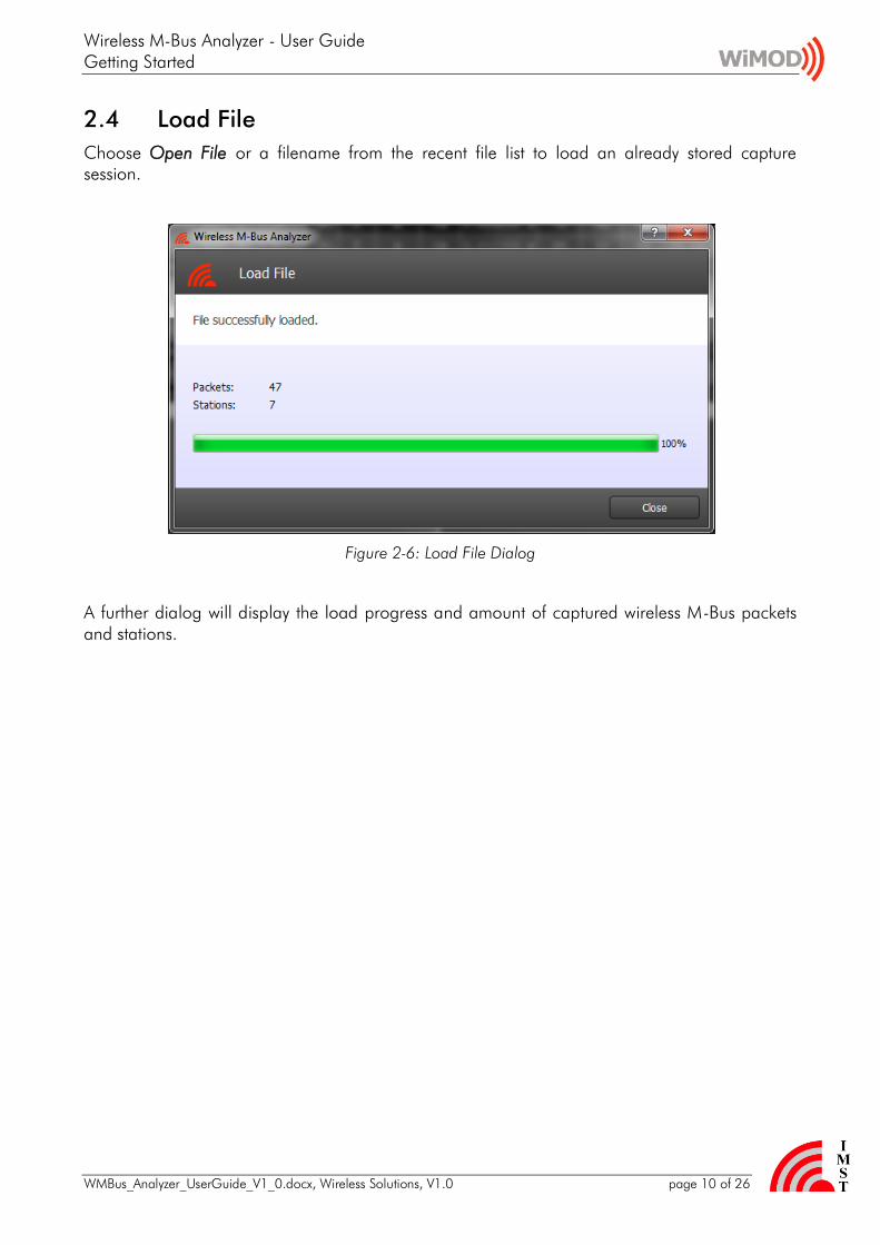

Wireless M-Bus Analyzer - User Guide Data Views
WMBus_Analyzer_UserGuide_V1_0docx Wireless Solutions V10 page 13 of 26
32 Message View
The Message View displays the captured messages in a more detailed way Each message is displayed as a row of several boxes which contain the individual header fields data blocks and CRC Fields
Note A corrupted header block or data block with wrong CRC value is marked with a following red colored CRC Field
Figure 3-2 Message View
As in the Table View the message content can be displayed in several ways
Simple octet sequence
Link Layer Header + Blocks and CRCs
Link Layer Header + higher Layer Protocol Segments
Furthermore it is possible to select a single message for detailed analysis of its content The selected message will be displayed in the Message Tree amp Memory View (see next chapters)
Wireless M-Bus Analyzer - User Guide Data Views
WMBus_Analyzer_UserGuide_V1_0docx Wireless Solutions V10 page 14 of 26
33 Message Tree View amp Memory View
The Message Tree View and Memory View display a single selected message in more detail
Figure 3-3 Message Tree amp Memory View
The Tree View contains three top level sections which can be expanded to display the more information
Packet Info
WM-Bus Message Blocks
WM-Bus Message Fields
331 Packet Info
This section contains general packet information eg Date Time RSSI Air Time
332 Wireless M-Bus Message Blocks
Within this section a single message is displayed according to its wireless M-Bus Link Layer Blocks
one single Header Block + CRC Field (16 Bit)
up-to 16 Data Blocks + individual CRC Fields (16 Bit)
Each block is displayed as a row of data bytes in hexadecimal format and a separate row of CRC bytes In case of a CRC Error the complete block is displayed in red
Selecting a single row within a block of the tree structure highlights the corresponding data bytes and CRC bytes in the Memory View on the right side
Wireless M-Bus Analyzer - User Guide Data Views
WMBus_Analyzer_UserGuide_V1_0docx Wireless Solutions V10 page 15 of 26
333 Wireless M-Bus Message Fields
Error free messages with correct CRC values are also displayed according to the logical layer structure of the wireless M-Bus specification
Link Layer
Extended Link Layer
Transport Layer
Application Layer
Figure 3-4 Wireless M-Bus Message Fields
The Application Layer Fields are only displayed if the message is not encrypted or if it is possible to decrypt the message successfully The message decryption is triggered automatically when a message is selected The decryption process looks for a configured AES key in the AES Key Store (see next chapter) and decrypts the Application Layer message content according to the signalled and supported decryption algorithm On successful decryption the Application Layer Fields will be parsed and the data in the Memory View will be displayed in a decrypted state
Wireless M-Bus Analyzer - User Guide Data Views
WMBus_Analyzer_UserGuide_V1_0docx Wireless Solutions V10 page 16 of 26
34 Traffic Monitor
The Traffic Monitor View allows to inspect the amount of captured radio packets and corresponding traffic in terms of air time and duty cycle per wireless M-Bus node
Figure 3-5 Traffic Monitor View
For every discovered wireless M-Bus node the following information is presented
Man ID Device ID Version Type the device identifying bytes from the wireless M-Bus message header
Packets the number of total packets error free (good) packets and CRC error packets
Duration the time span between the start of the first and last received packet used for the average duty cycle calculation
Air Time the cumulated air time of all captured packets per node
Average Duty Cycle (avg DC) the average duty cycle based on the cumulated air time and measurement duration
Duty Cycle last Hour the duty cycle based on all captured packets within the last hour
Max Duty Cycle per Hour the max duty cycle observed in a time span of one hour
Notes
The air time calculation does not include the long preambles which are use for nodes which operate in Link Mode S1
The packet arrival time stamp is derived from the Host PCs clock and may jitter according to other application (processes) which run in parallel to this program
Wireless M-Bus Analyzer - User Guide Data Views
WMBus_Analyzer_UserGuide_V1_0docx Wireless Solutions V10 page 17 of 26
35 AES Key Store
The AES Key Store dialog can be used to configure several AES Keys for decryption purpose According to the wireless M-Bus specification the Application Layer message content might be encrypted
Important Note all captured messages are stored in encrypted format The decryption is only triggered if a message is selected in one of the provided Message Views
Figure 3-6 AES Key Store
For message decryption purpose an AES key is selected according to its wireless M-Bus Device Header Fields Man ID Device ID Version and Type
Important Note All AES Keys which are visible in the Key Store will be stored in CUsersUSERNAMEAppDataLocalIMSTWMBus_AnalyzerWMBus_Analyzerini 1)
1) USERNAME is a placeholder for your windows user name
Export Keys Import Keys The content of the AES Key store can be exported and re-imported on another PC by means of this feature
Wireless M-Bus Analyzer - User Guide Data Views
WMBus_Analyzer_UserGuide_V1_0docx Wireless Solutions V10 page 18 of 26
36 Settings
The Settings dialog provides an easy configuration mean for several options
Figure 3-7 Settings
Message Columns
The column layout which is used in the Table View and Message View can be adapted by checkingunchecking the corresponding column title
WM-Bus Message Display Format
The content of a message can be displayed in three different ways
Simple octets sequence
Detailed Link Layer Header + Blocks with CRCs
Detailed Link Layer Header + higher Protocol Layer Segments
Scroll Behaviour
The automatic scroll behaviour of Table View and Message View while capturing messages can be enabled disabled here
Wireless M-Bus Analyzer - User Guide Data Views
WMBus_Analyzer_UserGuide_V1_0docx Wireless Solutions V10 page 19 of 26
37 Overview
The Overview box gives a short overview about the number of captured packets CRC errors discovered wireless M-Bus stations and capture session time
Figure 3-8 Overview
38 Message Filter
The Message Filter box provides an easy mean to reduce the amount of displayed wireless M-Bus messages Only those messages are displayed which Link Layer Header Fields (LLA) matches to the configured and enabled (checked) filter settings
Figure 3-9 Message Filter
Note A right mouse click on a particular row in the Table View Message View or Traffic Monitor provides a simple mean to copy the address fields of the selected row directly to the filter box
Wireless M-Bus Analyzer - User Guide Data Views
WMBus_Analyzer_UserGuide_V1_0docx Wireless Solutions V10 page 20 of 26
39 Firmware Update
To enable further feature enhancements of this tool and the required PA-iM871A radio modules a firmware update support is provides The update dialog verifies the available and currently used version of the radio modules firmware and guides through the update process
Figure 3-10 Firmware Update
Wireless M-Bus Analyzer - User Guide Data Views
WMBus_Analyzer_UserGuide_V1_0docx Wireless Solutions V10 page 21 of 26
310 Software Update
The Analyzer PC application itself can be updated via HTTPs Select SoftwareUpdate from the main menu to query for a new software version
Figure 3-11 Software Update
Wireless M-Bus Analyzer - User Guide Data Views
WMBus_Analyzer_UserGuide_V1_0docx Wireless Solutions V10 page 22 of 26
311 Customer specific Feature Extensions
The new About dialog provides a list of features which are supported or not supported in the installed version
Figure 3-12 About Dialog ndash Supported Features
Wireless M-Bus Analyzer - User Guide Appendix
WMBus_Analyzer_UserGuide_V1_0docx Wireless Solutions V10 page 23 of 26
4 Appendix
41 List of Abbreviations
FW Firmware
GUI Graphical User Interface
HW Hardware
RSSI Received Signal Strength Indicator
RTC Real Time Clock
SW Software
UART Universal Asynchronous ReceiverTransmitter
42 List of Figures
Figure 1-1 USB Driver Installation 4
Figure 2-1 Single Radio Mode (connected PA-iM871A at COM 87) 6
Figure 2-2 Dual Radio Mode (connected PA-iM871A at COM 85 + 87) 6
Figure 2-3 Select Link Mode (Dual Radio Mode Configuration for T-Mode) 7
Figure 2-4 File Save Dialog 8
Figure 2-5 File Save Dialog 8
Figure 2-6 Load File Dialog 10
Figure 3-1 Table View 11
Figure 3-2 Message View 13
Figure 3-3 Message Tree amp Memory View 14
Figure 3-4 Wireless M-Bus Message Fields 15
Figure 3-5 Traffic Monitor View 16
Figure 3-6 AES Key Store 17
Figure 3-7 Settings 18
Figure 3-8 Overview 19
Figure 3-9 Message Filter 19
Figure 3-10 Firmware Update 20
Wireless M-Bus Analyzer - User Guide Appendix
WMBus_Analyzer_UserGuide_V1_0docx Wireless Solutions V10 page 24 of 26
Figure 3-11 Software Update 21
Figure 3-12 About Dialog ndash Supported Features 22
Wireless M-Bus Analyzer - User Guide Regulatory Compliance Information
WMBus_Analyzer_UserGuide_V1_0docx Wireless Solutions V10 page 25 of 26
5 Regulatory Compliance Information
The use of radio frequencies is limited by national regulations The radio module has been designed to comply with the European Unionrsquos RampTTE (Radio amp Telecommunications Terminal Equipment) directive 19995EC and can be used free of charge within the European Union Nevertheless restrictions in terms of maximum allowed RF power or duty cycle may apply
The radio module has been designed to be embedded into other products (referred as ldquofinal productsrdquo) According to the RampTTE directive the declaration of compliance with essential requirements of the RampTTE directive is within the responsibility of the manufacturer of the final product A declaration of conformity for the radio module is available from IMST GmbH on request
The applicable regulation requirements are subject to change IMST GmbH does not take any responsibility for the correctness and accuracy of the aforementioned information National laws and regulations as well as their interpretation can vary with the country In case of uncertainty it is recommended to contact either IMSTrsquos accredited Test Center or to consult the local authorities of the relevant countries
Wireless M-Bus Analyzer - User Guide Important Notice
WMBus_Analyzer_UserGuide_V1_0docx Wireless Solutions V10 page 26 of 26
6 Important Notice
61 Disclaimer
IMST GmbH points out that all information in this document is given on an ldquoas isrdquo basis No guarantee neither explicit nor implicit is given for the correctness at the time of publication IMST GmbH reserves all rights to make corrections modifications enhancements and other changes to its products and services at any time and to discontinue any product or service without prior notice It is recommended for customers to refer to the latest relevant information before placing orders and to verify that such information is current and complete All products are sold and delivered subject to ldquoGeneral Terms and Conditionsrdquo of IMST GmbH supplied at the time of order acknowledgment
IMST GmbH assumes no liability for the use of its products and does not grant any licenses for its patent rights or for any other of its intellectual property rights or third-party rights It is the customerrsquos duty to bear responsibility for compliance of systems or units in which products from IMST GmbH are integrated with applicable legal regulations Customers should provide adequate design and operating safeguards to minimize the risks associated with customer products and applications The products are not approved for use in life supporting systems or other systems whose malfunction could result in personal injury to the user Customers using the products within such applications do so at their own risk
Any reproduction of information in datasheets of IMST GmbH is permissible only if reproduction is without alteration and is accompanied by all given associated warranties conditions limitations and notices Any resale of IMST GmbH products or services with statements different from or beyond the parameters stated by IMST GmbH for that productsolution or service is not allowed and voids all express and any implied warranties The limitations on liability in favor of IMST GmbH shall also affect its employees executive personnel and bodies in the same way IMST GmbH is not responsible or liable for any such wrong statements
Copyright copy 2011 IMST GmbH
62 Contact Information
IMST GmbH
Carl-Friedrich-Gauss-Str 2-4 47475 Kamp-Lintfort Germany
T +49 2842 981 0 F +49 2842 981 299 E wimodimstde I wwwwireless-solutionsde
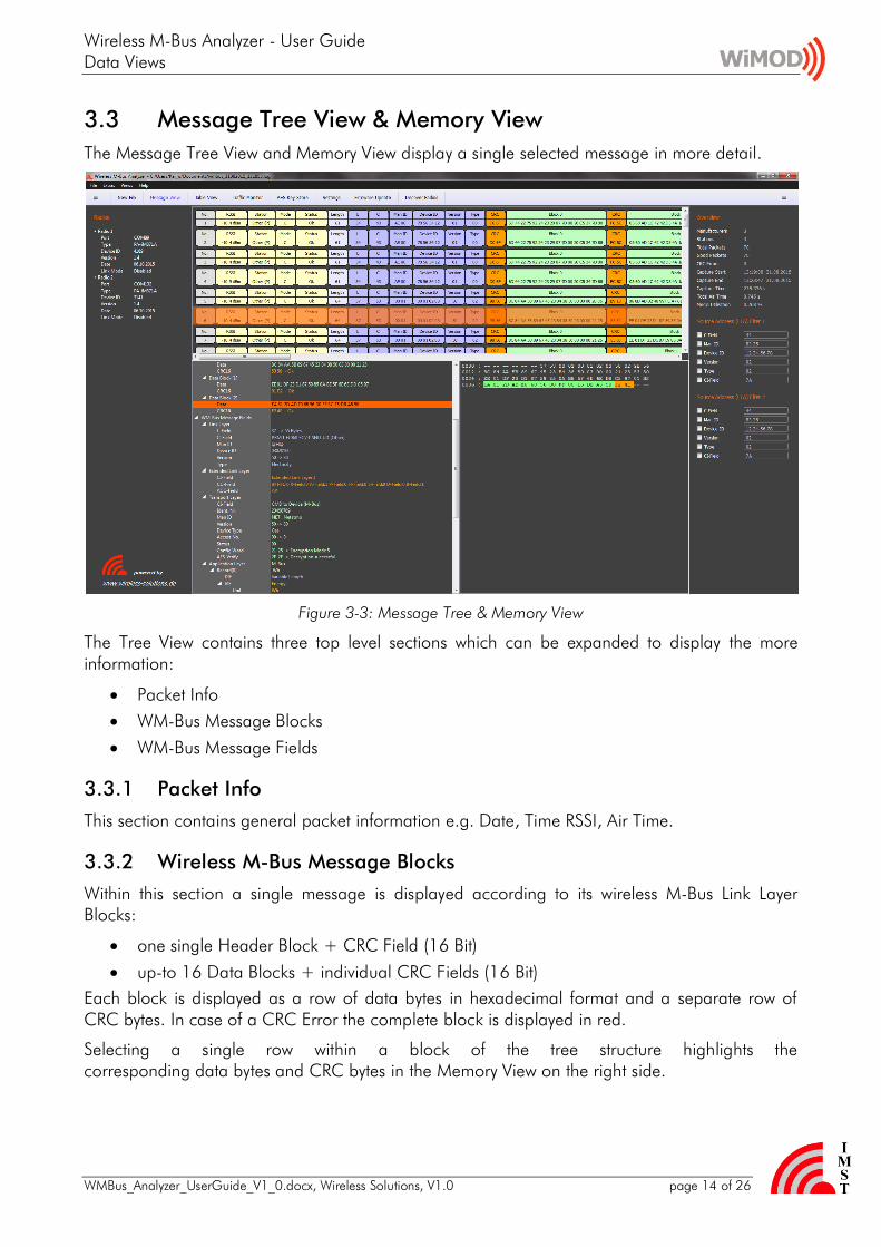
Wireless M-Bus Analyzer - User Guide Data Views
WMBus_Analyzer_UserGuide_V1_0docx Wireless Solutions V10 page 16 of 26
34 Traffic Monitor
The Traffic Monitor View allows to inspect the amount of captured radio packets and corresponding traffic in terms of air time and duty cycle per wireless M-Bus node
Figure 3-5 Traffic Monitor View
For every discovered wireless M-Bus node the following information is presented
Man ID Device ID Version Type the device identifying bytes from the wireless M-Bus message header
Packets the number of total packets error free (good) packets and CRC error packets
Duration the time span between the start of the first and last received packet used for the average duty cycle calculation
Air Time the cumulated air time of all captured packets per node
Average Duty Cycle (avg DC) the average duty cycle based on the cumulated air time and measurement duration
Duty Cycle last Hour the duty cycle based on all captured packets within the last hour
Max Duty Cycle per Hour the max duty cycle observed in a time span of one hour
Notes
The air time calculation does not include the long preambles which are use for nodes which operate in Link Mode S1
The packet arrival time stamp is derived from the Host PCs clock and may jitter according to other application (processes) which run in parallel to this program
Wireless M-Bus Analyzer - User Guide Data Views
WMBus_Analyzer_UserGuide_V1_0docx Wireless Solutions V10 page 17 of 26
35 AES Key Store
The AES Key Store dialog can be used to configure several AES Keys for decryption purpose According to the wireless M-Bus specification the Application Layer message content might be encrypted
Important Note all captured messages are stored in encrypted format The decryption is only triggered if a message is selected in one of the provided Message Views
Figure 3-6 AES Key Store
For message decryption purpose an AES key is selected according to its wireless M-Bus Device Header Fields Man ID Device ID Version and Type
Important Note All AES Keys which are visible in the Key Store will be stored in CUsersUSERNAMEAppDataLocalIMSTWMBus_AnalyzerWMBus_Analyzerini 1)
1) USERNAME is a placeholder for your windows user name
Export Keys Import Keys The content of the AES Key store can be exported and re-imported on another PC by means of this feature
Wireless M-Bus Analyzer - User Guide Data Views
WMBus_Analyzer_UserGuide_V1_0docx Wireless Solutions V10 page 18 of 26
36 Settings
The Settings dialog provides an easy configuration mean for several options
Figure 3-7 Settings
Message Columns
The column layout which is used in the Table View and Message View can be adapted by checkingunchecking the corresponding column title
WM-Bus Message Display Format
The content of a message can be displayed in three different ways
Simple octets sequence
Detailed Link Layer Header + Blocks with CRCs
Detailed Link Layer Header + higher Protocol Layer Segments
Scroll Behaviour
The automatic scroll behaviour of Table View and Message View while capturing messages can be enabled disabled here
Wireless M-Bus Analyzer - User Guide Data Views
WMBus_Analyzer_UserGuide_V1_0docx Wireless Solutions V10 page 19 of 26
37 Overview
The Overview box gives a short overview about the number of captured packets CRC errors discovered wireless M-Bus stations and capture session time
Figure 3-8 Overview
38 Message Filter
The Message Filter box provides an easy mean to reduce the amount of displayed wireless M-Bus messages Only those messages are displayed which Link Layer Header Fields (LLA) matches to the configured and enabled (checked) filter settings
Figure 3-9 Message Filter
Note A right mouse click on a particular row in the Table View Message View or Traffic Monitor provides a simple mean to copy the address fields of the selected row directly to the filter box
Wireless M-Bus Analyzer - User Guide Data Views
WMBus_Analyzer_UserGuide_V1_0docx Wireless Solutions V10 page 20 of 26
39 Firmware Update
To enable further feature enhancements of this tool and the required PA-iM871A radio modules a firmware update support is provides The update dialog verifies the available and currently used version of the radio modules firmware and guides through the update process
Figure 3-10 Firmware Update
Wireless M-Bus Analyzer - User Guide Data Views
WMBus_Analyzer_UserGuide_V1_0docx Wireless Solutions V10 page 21 of 26
310 Software Update
The Analyzer PC application itself can be updated via HTTPs Select SoftwareUpdate from the main menu to query for a new software version
Figure 3-11 Software Update
Wireless M-Bus Analyzer - User Guide Data Views
WMBus_Analyzer_UserGuide_V1_0docx Wireless Solutions V10 page 22 of 26
311 Customer specific Feature Extensions
The new About dialog provides a list of features which are supported or not supported in the installed version
Figure 3-12 About Dialog ndash Supported Features
Wireless M-Bus Analyzer - User Guide Appendix
WMBus_Analyzer_UserGuide_V1_0docx Wireless Solutions V10 page 23 of 26
4 Appendix
41 List of Abbreviations
FW Firmware
GUI Graphical User Interface
HW Hardware
RSSI Received Signal Strength Indicator
RTC Real Time Clock
SW Software
UART Universal Asynchronous ReceiverTransmitter
42 List of Figures
Figure 1-1 USB Driver Installation 4
Figure 2-1 Single Radio Mode (connected PA-iM871A at COM 87) 6
Figure 2-2 Dual Radio Mode (connected PA-iM871A at COM 85 + 87) 6
Figure 2-3 Select Link Mode (Dual Radio Mode Configuration for T-Mode) 7
Figure 2-4 File Save Dialog 8
Figure 2-5 File Save Dialog 8
Figure 2-6 Load File Dialog 10
Figure 3-1 Table View 11
Figure 3-2 Message View 13
Figure 3-3 Message Tree amp Memory View 14
Figure 3-4 Wireless M-Bus Message Fields 15
Figure 3-5 Traffic Monitor View 16
Figure 3-6 AES Key Store 17
Figure 3-7 Settings 18
Figure 3-8 Overview 19
Figure 3-9 Message Filter 19
Figure 3-10 Firmware Update 20
Wireless M-Bus Analyzer - User Guide Appendix
WMBus_Analyzer_UserGuide_V1_0docx Wireless Solutions V10 page 24 of 26
Figure 3-11 Software Update 21
Figure 3-12 About Dialog ndash Supported Features 22
Wireless M-Bus Analyzer - User Guide Regulatory Compliance Information
WMBus_Analyzer_UserGuide_V1_0docx Wireless Solutions V10 page 25 of 26
5 Regulatory Compliance Information
The use of radio frequencies is limited by national regulations The radio module has been designed to comply with the European Unionrsquos RampTTE (Radio amp Telecommunications Terminal Equipment) directive 19995EC and can be used free of charge within the European Union Nevertheless restrictions in terms of maximum allowed RF power or duty cycle may apply
The radio module has been designed to be embedded into other products (referred as ldquofinal productsrdquo) According to the RampTTE directive the declaration of compliance with essential requirements of the RampTTE directive is within the responsibility of the manufacturer of the final product A declaration of conformity for the radio module is available from IMST GmbH on request
The applicable regulation requirements are subject to change IMST GmbH does not take any responsibility for the correctness and accuracy of the aforementioned information National laws and regulations as well as their interpretation can vary with the country In case of uncertainty it is recommended to contact either IMSTrsquos accredited Test Center or to consult the local authorities of the relevant countries
Wireless M-Bus Analyzer - User Guide Important Notice
WMBus_Analyzer_UserGuide_V1_0docx Wireless Solutions V10 page 26 of 26
6 Important Notice
61 Disclaimer
IMST GmbH points out that all information in this document is given on an ldquoas isrdquo basis No guarantee neither explicit nor implicit is given for the correctness at the time of publication IMST GmbH reserves all rights to make corrections modifications enhancements and other changes to its products and services at any time and to discontinue any product or service without prior notice It is recommended for customers to refer to the latest relevant information before placing orders and to verify that such information is current and complete All products are sold and delivered subject to ldquoGeneral Terms and Conditionsrdquo of IMST GmbH supplied at the time of order acknowledgment
IMST GmbH assumes no liability for the use of its products and does not grant any licenses for its patent rights or for any other of its intellectual property rights or third-party rights It is the customerrsquos duty to bear responsibility for compliance of systems or units in which products from IMST GmbH are integrated with applicable legal regulations Customers should provide adequate design and operating safeguards to minimize the risks associated with customer products and applications The products are not approved for use in life supporting systems or other systems whose malfunction could result in personal injury to the user Customers using the products within such applications do so at their own risk
Any reproduction of information in datasheets of IMST GmbH is permissible only if reproduction is without alteration and is accompanied by all given associated warranties conditions limitations and notices Any resale of IMST GmbH products or services with statements different from or beyond the parameters stated by IMST GmbH for that productsolution or service is not allowed and voids all express and any implied warranties The limitations on liability in favor of IMST GmbH shall also affect its employees executive personnel and bodies in the same way IMST GmbH is not responsible or liable for any such wrong statements
Copyright copy 2011 IMST GmbH
62 Contact Information
IMST GmbH
Carl-Friedrich-Gauss-Str 2-4 47475 Kamp-Lintfort Germany
T +49 2842 981 0 F +49 2842 981 299 E wimodimstde I wwwwireless-solutionsde
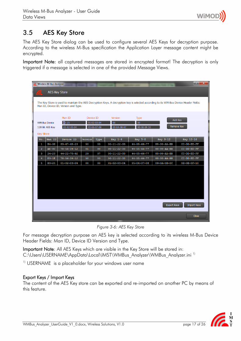
Wireless M-Bus Analyzer - User Guide Data Views
WMBus_Analyzer_UserGuide_V1_0docx Wireless Solutions V10 page 22 of 26
311 Customer specific Feature Extensions
The new About dialog provides a list of features which are supported or not supported in the installed version
Figure 3-12 About Dialog ndash Supported Features
Wireless M-Bus Analyzer - User Guide Appendix
WMBus_Analyzer_UserGuide_V1_0docx Wireless Solutions V10 page 23 of 26
4 Appendix
41 List of Abbreviations
FW Firmware
GUI Graphical User Interface
HW Hardware
RSSI Received Signal Strength Indicator
RTC Real Time Clock
SW Software
UART Universal Asynchronous ReceiverTransmitter
42 List of Figures
Figure 1-1 USB Driver Installation 4
Figure 2-1 Single Radio Mode (connected PA-iM871A at COM 87) 6
Figure 2-2 Dual Radio Mode (connected PA-iM871A at COM 85 + 87) 6
Figure 2-3 Select Link Mode (Dual Radio Mode Configuration for T-Mode) 7
Figure 2-4 File Save Dialog 8
Figure 2-5 File Save Dialog 8
Figure 2-6 Load File Dialog 10
Figure 3-1 Table View 11
Figure 3-2 Message View 13
Figure 3-3 Message Tree amp Memory View 14
Figure 3-4 Wireless M-Bus Message Fields 15
Figure 3-5 Traffic Monitor View 16
Figure 3-6 AES Key Store 17
Figure 3-7 Settings 18
Figure 3-8 Overview 19
Figure 3-9 Message Filter 19
Figure 3-10 Firmware Update 20
Wireless M-Bus Analyzer - User Guide Appendix
WMBus_Analyzer_UserGuide_V1_0docx Wireless Solutions V10 page 24 of 26
Figure 3-11 Software Update 21
Figure 3-12 About Dialog ndash Supported Features 22
Wireless M-Bus Analyzer - User Guide Regulatory Compliance Information
WMBus_Analyzer_UserGuide_V1_0docx Wireless Solutions V10 page 25 of 26
5 Regulatory Compliance Information
The use of radio frequencies is limited by national regulations The radio module has been designed to comply with the European Unionrsquos RampTTE (Radio amp Telecommunications Terminal Equipment) directive 19995EC and can be used free of charge within the European Union Nevertheless restrictions in terms of maximum allowed RF power or duty cycle may apply
The radio module has been designed to be embedded into other products (referred as ldquofinal productsrdquo) According to the RampTTE directive the declaration of compliance with essential requirements of the RampTTE directive is within the responsibility of the manufacturer of the final product A declaration of conformity for the radio module is available from IMST GmbH on request
The applicable regulation requirements are subject to change IMST GmbH does not take any responsibility for the correctness and accuracy of the aforementioned information National laws and regulations as well as their interpretation can vary with the country In case of uncertainty it is recommended to contact either IMSTrsquos accredited Test Center or to consult the local authorities of the relevant countries
Wireless M-Bus Analyzer - User Guide Important Notice
WMBus_Analyzer_UserGuide_V1_0docx Wireless Solutions V10 page 26 of 26
6 Important Notice
61 Disclaimer
IMST GmbH points out that all information in this document is given on an ldquoas isrdquo basis No guarantee neither explicit nor implicit is given for the correctness at the time of publication IMST GmbH reserves all rights to make corrections modifications enhancements and other changes to its products and services at any time and to discontinue any product or service without prior notice It is recommended for customers to refer to the latest relevant information before placing orders and to verify that such information is current and complete All products are sold and delivered subject to ldquoGeneral Terms and Conditionsrdquo of IMST GmbH supplied at the time of order acknowledgment
IMST GmbH assumes no liability for the use of its products and does not grant any licenses for its patent rights or for any other of its intellectual property rights or third-party rights It is the customerrsquos duty to bear responsibility for compliance of systems or units in which products from IMST GmbH are integrated with applicable legal regulations Customers should provide adequate design and operating safeguards to minimize the risks associated with customer products and applications The products are not approved for use in life supporting systems or other systems whose malfunction could result in personal injury to the user Customers using the products within such applications do so at their own risk
Any reproduction of information in datasheets of IMST GmbH is permissible only if reproduction is without alteration and is accompanied by all given associated warranties conditions limitations and notices Any resale of IMST GmbH products or services with statements different from or beyond the parameters stated by IMST GmbH for that productsolution or service is not allowed and voids all express and any implied warranties The limitations on liability in favor of IMST GmbH shall also affect its employees executive personnel and bodies in the same way IMST GmbH is not responsible or liable for any such wrong statements
Copyright copy 2011 IMST GmbH
62 Contact Information
IMST GmbH
Carl-Friedrich-Gauss-Str 2-4 47475 Kamp-Lintfort Germany
T +49 2842 981 0 F +49 2842 981 299 E wimodimstde I wwwwireless-solutionsde

Wireless M-Bus Analyzer - User Guide Appendix
WMBus_Analyzer_UserGuide_V1_0docx Wireless Solutions V10 page 24 of 26
Figure 3-11 Software Update 21
Figure 3-12 About Dialog ndash Supported Features 22
Wireless M-Bus Analyzer - User Guide Regulatory Compliance Information
WMBus_Analyzer_UserGuide_V1_0docx Wireless Solutions V10 page 25 of 26
5 Regulatory Compliance Information
The use of radio frequencies is limited by national regulations The radio module has been designed to comply with the European Unionrsquos RampTTE (Radio amp Telecommunications Terminal Equipment) directive 19995EC and can be used free of charge within the European Union Nevertheless restrictions in terms of maximum allowed RF power or duty cycle may apply
The radio module has been designed to be embedded into other products (referred as ldquofinal productsrdquo) According to the RampTTE directive the declaration of compliance with essential requirements of the RampTTE directive is within the responsibility of the manufacturer of the final product A declaration of conformity for the radio module is available from IMST GmbH on request
The applicable regulation requirements are subject to change IMST GmbH does not take any responsibility for the correctness and accuracy of the aforementioned information National laws and regulations as well as their interpretation can vary with the country In case of uncertainty it is recommended to contact either IMSTrsquos accredited Test Center or to consult the local authorities of the relevant countries
Wireless M-Bus Analyzer - User Guide Important Notice
WMBus_Analyzer_UserGuide_V1_0docx Wireless Solutions V10 page 26 of 26
6 Important Notice
61 Disclaimer
IMST GmbH points out that all information in this document is given on an ldquoas isrdquo basis No guarantee neither explicit nor implicit is given for the correctness at the time of publication IMST GmbH reserves all rights to make corrections modifications enhancements and other changes to its products and services at any time and to discontinue any product or service without prior notice It is recommended for customers to refer to the latest relevant information before placing orders and to verify that such information is current and complete All products are sold and delivered subject to ldquoGeneral Terms and Conditionsrdquo of IMST GmbH supplied at the time of order acknowledgment
IMST GmbH assumes no liability for the use of its products and does not grant any licenses for its patent rights or for any other of its intellectual property rights or third-party rights It is the customerrsquos duty to bear responsibility for compliance of systems or units in which products from IMST GmbH are integrated with applicable legal regulations Customers should provide adequate design and operating safeguards to minimize the risks associated with customer products and applications The products are not approved for use in life supporting systems or other systems whose malfunction could result in personal injury to the user Customers using the products within such applications do so at their own risk
Any reproduction of information in datasheets of IMST GmbH is permissible only if reproduction is without alteration and is accompanied by all given associated warranties conditions limitations and notices Any resale of IMST GmbH products or services with statements different from or beyond the parameters stated by IMST GmbH for that productsolution or service is not allowed and voids all express and any implied warranties The limitations on liability in favor of IMST GmbH shall also affect its employees executive personnel and bodies in the same way IMST GmbH is not responsible or liable for any such wrong statements
Copyright copy 2011 IMST GmbH
62 Contact Information
IMST GmbH
Carl-Friedrich-Gauss-Str 2-4 47475 Kamp-Lintfort Germany
T +49 2842 981 0 F +49 2842 981 299 E wimodimstde I wwwwireless-solutionsde