wireless intrusion detection system - cisco.com · wireless intrusion detection system •...
TRANSCRIPT

Wireless Intrusion Detection System
• Management Frame Protection, page 1
• Client Exclusion Policies, page 5
• Rogue Management, page 7
• Cisco Intrusion Detection System, page 32
• IDS Signatures, page 35
• SNMP, page 43
• wIPS, page 48
Management Frame Protection
Information About Management Frame ProtectionManagement frame protection (MFP) provides security for the otherwise unprotected and unencrypted 802.11management messages passed between access points and clients. MFP provides both infrastructure and clientsupport.
• Infrastructure MFP—Protects management frames by detecting adversaries that are invokingdenial-of-service attacks, flooding the network with associations and probes, interjecting as rogue accesspoints, and affecting network performance by attacking the QoS and radio measurement frames.Infrastructure MFP is a global setting that provides a quick and effective means to detect and reportphishing incidents.
Specifically, infrastructure MFP protects 802.11 session management functions by adding messageintegrity check information elements (MIC IEs) to the management frames emitted by access points(and not those emitted by clients), which are then validated by other access points in the network.Infrastructure MFP is passive. It can detect and report intrusions but has no means to stop them.
• ClientMFP—Shields authenticated clients from spoofed frames, preventingmany of the common attacksagainst wireless LANs from becoming effective. Most attacks, such as deauthentication attacks, revertto simply degrading performance by contending with valid clients.
Cisco Wireless Controller Configuration Guide, Release 8.3 1
Specifically, client MFP encrypts management frames are sent between access points and CCXv5 clientsso that both the access points and clients can take preventative action by dropping spoofed class 3management frames (that is, management frames passed between an access point and a client that isauthenticated and associated). Client MFP leverages the security mechanisms defined by IEEE 802.11ito protect the following types of class 3 unicast management frames: disassociation, deauthentication,and QoS (WMM) action. Client MFP protects a client-access point session from the most common typeof denial-of-service attack. It protects class 3 management frames by using the same encryption methodused for the session’s data frames. If a frame received by the access point or client fails decryption, it isdropped, and the event is reported to the controller.
To use client MFP, clients must support CCXv5 MFP and must negotiate WPA2 using either TKIP orAES-CCMP. EAP or PSKmay be used to obtain the PMK. CCKM and controller mobility managementare used to distribute session keys between access points for Layer 2 and Layer 3 fast roaming.
To prevent attacks using broadcast frames, access points supporting CCXv5 will notemit any broadcast class 3 management frames (such as disassociation, deauthentication,or action). CCXv5 clients and access points must discard broadcast class 3 managementframes.
ClientMFP supplements infrastructureMFP rather than replaces it because infrastructureMFP continues to detect and report invalid unicast frames sent to clients that are notclient-MFP capable as well as invalid class 1 and 2 management frames. InfrastructureMFP is applied only to management frames that are not protected by client MFP.
Infrastructure MFP consists of three main components:
Note
• Management frame protection—The access point protects the management frames it transmits by addinga MIC IE to each frame. Any attempt to copy, alter, or replay the frame invalidates the MIC, causingany receiving access point configured to detect MFP frames to report the discrepancy. MFP is supportedfor use with Cisco Aironet lightweight access points.
• Management frame validation—In infrastructure MFP, the access point validates every managementframe that it receives from other access points in the network. It ensures that theMIC IE is present (whenthe originator is configured to transmit MFP frames) and matches the content of the management frame.If it receives any frame that does not contain a valid MIC IE from a BSSID belonging to an access pointthat is configured to transmitMFP frames, it reports the discrepancy to the networkmanagement system.In order for the timestamps to operate properly, all controllers must be Network Time Protocol (NTP)synchronized.
• Event reporting—The access point notifies the controller when it detects an anomaly, and the controlleraggregates the received anomaly events and can report the results through SNMP traps to the networkmanagement system.
Client MFP uses the same event reporting mechanisms as infrastructure MFP.Note
Infrastructure MFP is disabled by default and can be enabled globally. When you upgrade from a previoussoftware release, infrastructure MFP is disabled globally if access point authentication is enabled because thetwo features are mutually exclusive. Once infrastructureMFP is enabled globally, signature generation (addingMICs to outbound frames) can be disabled for selected WLANs, and validation can be disabled for selectedaccess points.
Cisco Wireless Controller Configuration Guide, Release 8.32
Wireless Intrusion Detection SystemInformation About Management Frame Protection

Client MFP is enabled by default on WLANs that are configured for WPA2. It can be disabled, or it can bemademandatory (in which case, only clients that negotiateMFP are allowed to associate) on selectedWLANs.
Restrictions for Management Frame Protection• Lightweight access points support infrastructure MFP in local and monitor modes and in FlexConnectmode when the access point is connected to a controller. They support client MFP in local, FlexConnect,and bridge modes.
• OEAP 600 Series Access points do not support MFP.
• Client MFP is supported for use only with CCXv5 clients using WPA2 with TKIP or AES-CCMP.
• Non-CCXv5 clients may associate to a WLAN if client MFP is disabled or optional.
• Error reports generated on a FlexConnect access point in standalone mode cannot be forwarded to thecontroller and are dropped.
Configuring Management Frame Protection (GUI)
Step 1 Choose Security>Wireless Protection Policies > APAuthentication/MFP to open the APAuthentication Policy page.Step 2 Enable infrastructure MFP globally for the controller by choosingManagement Frame Protection from the Protection
Type drop-down list.Step 3 Click Apply to commit your changes.
If more than one controller is included in the mobility group, you must configure an NTP/SNTP server on allcontrollers in the mobility group that are configured for infrastructure MFP.
Note
Step 4 Configure client MFP for a particular WLAN after infrastructure MFP has been enabled globally for the controller asfollows:a) ChooseWLANs.b) Click the profile name of the desiredWLAN. TheWLANs > Edit page appears.c) Choose Advanced. The WLANs > Edit (Advanced) page appears.d) Choose Disabled, Optional, or Required from the MFP Client Protection drop-down list. The default value is
Optional. If you choose Required, clients are allowed to associate only if MFP is negotiated (that is, if WPA2 isconfigured on the controller and the client supports CCXv5 MFP and is also configured for WPA2).
For Cisco OEAP 600,MFP is not supported. It should either be Disabled or Optional.Note
e) Click Apply to commit your changes.
Step 5 Click Save Configuration to save your settings.
Viewing the Management Frame Protection Settings (GUI)To see the controller’s current global MFP settings, choose Security >Wireless Protection Policies >Management Frame Protection. The Management Frame Protection Settings page appears.
Cisco Wireless Controller Configuration Guide, Release 8.3 3
Wireless Intrusion Detection SystemRestrictions for Management Frame Protection

On this page, you can see the following MFP settings:
• TheManagement Frame Protection field shows if infrastructure MFP is enabled globally for thecontroller.
• TheController Time Source Valid field indicates whether the controller time is set locally (by manuallyentering the time) or through an external source (such as the NTP/SNTP server). If the time is set by anexternal source, the value of this field is “True.” If the time is set locally, the value is “False.” The timesource is used for validating the timestamp on management frames between access points of differentcontrollers within a mobility group.
• The Client Protection field shows if client MFP is enabled for individual WLANs and whether it isoptional or required.
Configuring Management Frame Protection (CLI)• Enable or disable infrastructure MFP globally for the controller by entering this command:config wps mfp infrastructure {enable | disable}
• Enable or disable client MFP on a specific WLAN by entering this command:config wlan mfp client {enable | disable} wlan_id [required ]
If you enable client MFP and use the optional required parameter, clients are allowed to associate onlyif MFP is negotiated.
Viewing the Management Frame Protection Settings (CLI)• See the controller’s current MFP settings by entering this command:show wps mfp summary
• See the current MFP configuration for a particular WLAN by entering this command:show wlan wlan_id
• See whether client MFP is enabled for a specific client by entering this command:show client detail client_mac
• See MFP statistics for the controller by entering this command:show wps mfp statistics
This report contains no data unless an active attack is in progress. This table is cleared every 5 minuteswhen the data is forwarded to any network management stations.
Note
Debugging Management Frame Protection Issues (CLI)• Use this command if you experience any problems with MFP:debug wps mfp ? {enable | disable}
where ? is one of the following:
Cisco Wireless Controller Configuration Guide, Release 8.34
Wireless Intrusion Detection SystemConfiguring Management Frame Protection (CLI)
client—Configures debugging for client MFP messages.
capwap—Configures debugging for MFP messages between the controller and access points.
detail—Configures detailed debugging for MFP messages.
report—Configures debugging for MFP reporting.
mm—Configures debugging for MFP mobility (inter-controller) messages.
Client Exclusion Policies
Configuring Client Exclusion Policies (GUI)
Step 1 Choose Security >Wireless Protection Policies > Client Exclusion Policies to open the Client Exclusion Policiespage.
Step 2 Select any of these check boxes if you want the controller to exclude clients for the condition specified. The default valuefor each exclusion policy is enabled.
• Excessive 802.11 Association Failures—Clients are excluded on the sixth 802.11 association attempt, after fiveconsecutive failures.
• Excessive 802.11 Authentication Failures—Clients are excluded on the sixth 802.11 authentication attempt, afterfive consecutive failures.
• Excessive 802.1X Authentication Failures—Clients are excluded on the fourth 802.1X authentication attempt,after three consecutive failures.
• IP Theft or IP Reuse—Clients are excluded if the IP address is already assigned to another device.
• Excessive Web Authentication Failures—Clients are excluded on the fourth web authentication attempt, afterthree consecutive failures.
Step 3 Save your configuration.
Configuring Client Exclusion Policies (CLI)
Step 1 Enable or disable the controller to exclude clients on the sixth 802.11 association attempt, after five consecutive failuresby entering this command:config wps client-exclusion 802.11-assoc {enable | disable}
Step 2 Enable or disable the controller to exclude clients on the sixth 802.11 authentication attempt, after five consecutivefailures by entering this command:
Cisco Wireless Controller Configuration Guide, Release 8.3 5
Wireless Intrusion Detection SystemClient Exclusion Policies

config wps client-exclusion 802.11-auth {enable | disable}Step 3 Enable or disable the controller to exclude clients on the fourth 802.1X authentication attempt, after three consecutive
failures by entering this command:config wps client-exclusion 802.1x-auth {enable | disable}
Step 4 Configure the controller to exclude clients that reaches the maximum failure 802.1X authentication attempt with theRADIUS server by entering this command:config wps client-exclusion 802.1x-auth max-1x-aaa-fail-attemptsYou can configure the maximum failure 802.1X authentication attempt from 1 to 3 and the default value is 3.
Step 5 Enable or disable the controller to exclude clients if the IP address is already assigned to another device by entering thiscommand:config wps client-exclusion ip-theft {enable | disable}
Step 6 Enable or disable the controller to exclude clients on the fourth web authentication attempt, after three consecutivefailures by entering this command:config wps client-exclusion web-auth {enable | disable}
Step 7 Enable or disable the controller to exclude clients for all of the above reasons by entering this command:config wps client-exclusion all {enable | disable}
Step 8 Use the following command to add or delete client exclusion entries.config exclusionlist {add mac-addr description | delete mac-addr | description mac-addr description}
Step 9 Save your changes by entering this command:save config
Step 10 See a list of clients that have been dynamically excluded, by entering this command:show exclusionlist
Information similar to the following appears:
Dynamically Disabled Clients----------------------------MAC Address Exclusion Reason Time Remaining (in secs)----------- ---------------- ------------------------
00:40:96:b4:82:55 802.1X Failure 51
Step 11 See the client exclusion policy configuration settings by entering this command:show wps summary
Information similar to the following appears:
Auto-ImmuneAuto-Immune.................................... Disabled
Client Exclusion PolicyExcessive 802.11-association failures.......... EnabledExcessive 802.11-authentication failures....... EnabledExcessive 802.1x-authentication................ EnabledIP-theft....................................... EnabledExcessive Web authentication failure........... EnabledMaximum 802.1x-AAA failure attempts............ 3
Signature PolicySignature Processing........................ Enabled
Cisco Wireless Controller Configuration Guide, Release 8.36
Wireless Intrusion Detection SystemConfiguring Client Exclusion Policies (CLI)

Rogue Management
Rogue Detection
Information About Rogue DevicesRogue access points can disrupt wireless LAN operations by hijacking legitimate clients and using plain-textor other denial-of-service or man-in-the-middle attacks. That is, a hacker can use a rogue access point tocapture sensitive information, such as usernames and passwords. The hacker can then transmit a series ofClear to Send (CTS) frames. This action mimics an access point, informing a particular client to transmit, andinstructing all the other clients to wait, which results in legitimate clients being unable to access networkresources. Wireless LAN service providers have a strong interest in banning rogue access points from the airspace.
Because rogue access points are inexpensive and readily available, employees sometimes plug unauthorizedrogue access points into existing LANs and build ad hoc wireless networks without their IT department'sknowledge or consent. These rogue access points can be a serious breach of network security because theycan be plugged into a network port behind the corporate firewall. Because employees generally do not enableany security settings on the rogue access point, it is easy for unauthorized users to use the access point tointercept network traffic and hijack client sessions. There is an increased chance of enterprise security breachwhen wireless users connect to access points in the enterprise network.
The following are some guidelines to manage rogue devices:
• The containment frames are sent immediately after the authorization and associations are detected. Theenhanced containment algorithm provides more effective containment of ad hoc clients.
• In a dense RF environment, where maximum rogue access points are suspected, the chances of detectingrogue access points by a local mode access point and FlexConnect mode access point in channel 157 orchannel 161 are less when compared to other channels. To mitigate this problem, we recommend thatyou use dedicated monitor mode access points.
• The local and FlexConnect mode access points are designed to serve associated clients. These accesspoints spend relatively less time performing off-channel scanning: about 50milliseconds on each channel.If you want to perform high rogue detection, a monitor mode access point must be used. Alternatively,you can reduce the scan intervals from 180 seconds to a lesser value, for example, 120 or 60 seconds,ensuring that the radio goes off-channel more frequently, which improves the chances of rogue detection.However, the access point will still spend about 50 milliseconds on each channel.
• Rogue detection is disabled by default for OfficeExtend access points because these access points, whichare deployed in a home environment, are likely to detect a large number of rogue devices.
• Client card implementations might mitigate the effectiveness of ad hoc containment.
• It is possible to classify and report rogue access points through the use of rogue states and user-definedclassification rules that enable rogues to automatically move between states.
• Each controller limits the number of rogue containment to three per radio (or six per radio for accesspoints in the monitor mode).
Cisco Wireless Controller Configuration Guide, Release 8.3 7
Wireless Intrusion Detection SystemRogue Management

• Rogue Location Discovery Protocol (RLDP) detects rogue access points that are configured for openauthentication.
• RLDP detects rogue access points that use a broadcast Basic Service Set Identifier (BSSID), that is, theaccess point broadcasts its Service Set Identifier in beacons.
• RLDP detects only those rogue access points that are on the same network. If an access list in the networkprevents the sending of RLDP traffic from the rogue access point to the controller, RLDP does not work.
• RLDP does not work on 5-GHz Dynamic Frequency Selection (DFS) channels. However, RLDP workswhen the managed access point is in the monitor mode on a DFS channel.
• If RLDP is enabled on mesh APs, and the APs perform RLDP tasks, the mesh APs are dissociated fromthe controller. The workaround is to disable RLDP on mesh APs.
• If RLDP is enabled on non-monitor APs, client connectivity outages occur when RLDP is in process.
• If the rogue is manually contained, the rogue entry is retained even after the rogue expires.
• If the rogue is contained by any other means, such as auto, rule, and AwIPS preventions, the rogue entryis deleted when it expires.
• The controller will request to AAA server for rogue client validation only once. As a result, if rogueclient validation fails on the first attempt then the rogue client will not be detected as a threat any more.To avoid this, add the valid client entries in the authentication server before enabling Validate RogueClients Against AAA.
• The controller has to be added to the AAA server as a AAA client with authentication as RADIUS(CISCOIOS/PIX 6.0). You must add the rogue AP in question to the userdatabase with relevant delimiter,username and password being the MAC address with relevant delimiter. You must define the [009\001]cisco-av-pair for this user with the following keywords:
◦rogue-ap-state=contain—Where, rogue-ap-state can be the following:alert/contain/internal/external/threat
◦rogue-ap-class=malicious—Where, rogue-ap-class can be following keywords:unclassified/malicious/friendly
The allowed combinations of class/state are:
◦unclassified—alert/contain/threat
◦malicious—alert/contain/threat
◦friendly—alert/internal/external
• All the valid client MAC details should be registered in the AAA authentication server with the sameMAC delimiter options as set in the RADIUS configuration on the controller. For more informationabout configuring MAC delimiter options, see the Configuring RADIUS (GUI) section.
• In the 7.4 and earlier releases, if a rogue that was already classified by a rule was not reclassified. In the7.5 release, this behavior is enhanced to allow reclassification of rogues based on the priority of therogue rule. The priority is determined by using the rogue report that is received by the controller.
• All rogues that are marked as friendly or contained state (due to auto or rule or manual) are stored inthe flash memory of the controller. When you reboot the controller loaded with Release 7.4, these roguesare shown as manually changed. If you wish to reboot the controller, you need to clear all rogue APsand rogue adhoc from the controller, save the configuration, and then reboot the controller.
Cisco Wireless Controller Configuration Guide, Release 8.38
Wireless Intrusion Detection SystemRogue Detection

• All rogues that are marked as friendly or contained state (only due to manual) are stored in the flashmemory of the controller. If you upgrade the controller from the Release 7.4 to 7.6 or later versions,then all rogues stored in the Release 7.4 are shown as manually classified (if friendly classified) ormanually contained. Hence after upgrading the controller from the Release 7.4 to 7.6 or later versions,you need to delete all rogue APs and rogue adhoc from the controller and then start configuring roguedetection.
• A FlexConnect AP (with rogue detection enabled) in the connected mode takes the containment listfrom the controller. If auto-contain SSID and auto contain adhoc are set in the controller, then theseconfigurations are set to all FlexConnect APs in the connected mode and the AP stores it in its memory.
When the FlexConnect AP moves to a standalone mode, the following tasks are performed:
◦The containment set by the controller continues.
◦If the FlexConnect AP detects any rogue AP that has same SSID as that of infra SSID (SSIDconfigured in the controller that the FlexConnect AP is connected to), then containment gets startedif auto contain SSID was enabled from the controller before moving to the standalone mode.
◦If the FlexConnect AP detects any adhoc rogue, containment gets started if auto-contain adhocwas enabled from the controller when it was in the connected mode.
When the standalone FlexConnect AP moves back to the connected mode, then the following tasks areperformed:
◦All containment gets cleared.
◦Containment initiated from the controller will take over.
• The rogue detector AP fails to co-relate and contain the wired rogue AP on a 5Mhz channel because theMAC address of the rogue AP forWLAN, LAN, 11a radio and 11bg radio are configured with a differenceof +/-1 of the rogue BSSID. In the 8.0 release, this behavior is enhanced by increasing the range of MACaddress, that the rogue detector AP co-relates the wired ARP MAC and rogue BSSID, by +/-3.
• The rogue access points with open authentication can be detected on wire. The NAT wired or roguewired detection is not supported in by WLC (both RLDP and rogue detector AP). The non-adjacentMAC address is supported by rogue detector mode of AP and not by RLDP.
• In a High Availability scenario, if the rogue detection security level is set to either High or Critical, therogue timer on the standby Cisco WLC starts only after the rogue detection pending stabilization time,which is 300 seconds. Therefore, the active configurations on the standby CiscoWLC are reflected onlyafter 300 seconds.
• After an AP is moved from rogue detection mode to any other mode, the rogue detection functionalityis not retained on the AP. To enable rogue detection functionality on the AP, you have to explicitly movethe AP to the rogue detection mode.
A rogue AP or client or adhoc containment configuration is not saved after the reload. You have to configureall the rogues again after the reload.
Note
Cisco Wireless Controller Configuration Guide, Release 8.3 9
Wireless Intrusion Detection SystemRogue Detection

No separate command exists for controlling rogue client traps. However, you can enable or disable rogueclient traps using the config trapflags rogueap {enable | disable} command, which is also used for rougeAPs. In GUI configuration also, you should use the rogue AP flag underManagement > SNMP >TrapControl > Security > Rogue AP to control rogue clients.
Note
Rogue Location Discovery Protocol
Rogue Location Discovery Protocol (RLDP) is an active approach, which is used when rogue AP has noauthentication (Open Authentication) configured. This mode, which is disabled by default, instructs an activeAP to move to the rogue channel and connect to the rogue as a client. During this time, the active AP sendsde-authentication messages to all connected clients and then shuts down the radio interface. Then, it associatesto the rogue AP as a client. The AP then tries to obtain an IP address from the rogue AP and forwards a UserDatagram Protocol (UDP) packet (port 6352) that contains the local AP and rogue connection information tothe controller through the rogue AP. If the controller receives this packet, the alarm is set to notify the networkadministrator that a rogue AP was discovered on the wired network with the RLDP feature.
RLDP has 100 % accuracy in rouge AP detection. It detects Open APs and NAT APs.
Use the debug dot11 rldp enable command in order to check if the Lightweight AP associates and receivesa DHCP address from the rogue AP. This command also displays the UDP packet sent by the LightweightAP to the controller.
Note
A sample of a UDP (destination port 6352) packet sent by the Lightweight AP is shown here: 0020 0a 01 010d 0a 01 .......(.*...... 0030 01 1e 00 07 85 92 78 01 00 00 00 00 00 00 00 00 ......x......... 0040 00 00 00 00 0000 00 00 00 00
The first 5 bytes of the data contain the DHCP address given to the local mode AP by the rogue AP. The next5 bytes are the IP address of the controller, followed by 6 bytes that represent the rogue AP MAC address.Then, there are 18 bytes of zeroes.
The following steps describe the functioning of RLDP:
1 Identify the closest Unified AP to the rogue using signal strength values.
2 The AP then connects to the rogue as a WLAN client, attempting three associations before timing out.
3 If association is successful, the AP then uses DHCP to obtain an IP address.
4 If an IP address was obtained, the AP (acting as a WLAN client) sends a UDP packet to each of thecontroller's IP addresses.
5 If the controller receives even one of the RLDP packets from the client, that rogue is marked as on-wire.
The RLDP packets are unable to reach the controller if filtering rules are placed between the controller'snetwork and the network where the rogue device is located.
Note
Caveats of RLDP:
• RLDP only works with open rogue APs broadcasting their SSID with authentication and encryptiondisabled.
Cisco Wireless Controller Configuration Guide, Release 8.310
Wireless Intrusion Detection SystemRogue Detection

• RLDP requires that the Managed AP acting as a client is able to obtain an IP address via DHCP on therogue network.
• Manual RLDP can be used to attempt an RLDP trace on a rogue multiple number of times.
• During RLDP process, the AP is unable to serve clients. This negatively impacts performance andconnectivity for local mode APs. To avoid this case, RLDP can be selectively enabled for Monitor ModeAP only.
• RLDP does not attempt to connect to a rogue AP operating in a 5GHz DFS channel.
RLDP is not supported for use with Cisco autonomous rogue access points. These access points drop theDHCP Discover request sent by the RLDP client. Also, RLDP is not supported if the rogue access pointchannel requires dynamic frequency selection (DFS). If the automatic RLDP attempt does not detect therogue (due to a noisy RF environment, for example), the controller does not retry. However, you caninitiate RLDP manually on a rogue device.
Note
Detecting Rogue Devices
The controller continuously monitors all the nearby access points and automatically discovers and collectsinformation on rogue access points and clients. When the controller discovers a rogue access point, it usesthe Rogue Location Discovery Protocol (RLDP) and the rogue detector mode access point is connected todetermine if the rogue is attached to your network.
Controller initiates RLDP on rogue devices that have open authenticated and configured. If RLDP usesFlexconnect or local mode access points, then clients are disconnected for that moment. After the RLDP cycle,the clients are reconnected to the access points. As and when rogue access points are seen (auto-configuration),the RLDP process is initiated.
You can configure the controller to use RLDP on all the access points or only on the access points configuredfor the monitor (listen-only) mode. The latter option facilitates automated rogue access point detection in acrowded radio frequency (RF) space, allowing monitoring without creating unnecessary interference andwithout affecting the regular data access point functionality. If you configure the controller to use RLDP onall the access points, the controller always chooses the monitor access point for RLDP operation if a monitoraccess point and a local (data) access point are both nearby. If RLDP determines that the rogue is on yournetwork, you can choose to contain the detected rogue either manually or automatically.
RLDP detects on wire presence of the rogue access points that are configured with open authentication onlyonce, which is the default retry configuration. Retries can be configured using the config rogue ap rldpretries command.
You can initiate or trigger RLDP from controller in three ways:
1 Enter the RLDP initiation command manually from the controller CLI. The equivalent GUI option forinitiating RLDP is not supported.
config rogue ap rldp initiate mac-address
2 Schedule RLDP from the controller CLI. The equivalent GUI option for scheduling RLDP is not supported.
config rogue ap rldp schedule
3 Auto RLDP. You can configure auto RLDP on controller either from controller CLI or GUI but keep inmind the following guidelines:
Cisco Wireless Controller Configuration Guide, Release 8.3 11
Wireless Intrusion Detection SystemRogue Detection

• The auto RLDP option can be configured only when the rogue detection security level is set tocustom.
• Either auto RLDP or schedule of RLDP can be enabled at a time.
A rogue access point is moved to a contained state either automatically or manually. The controller selectsthe best available access point for containment and pushes the information to the access point. The accesspoint stores the list of containments per radio. For auto containment, you can configure the controller to useonly the monitor mode access point. The containment operation occurs in the following two ways:
• The container access point goes through the list of containments periodically and sends unicastcontainment frames. For rogue access point containment, the frames are sent only if a rogue client isassociated.
•Whenever a contained rogue activity is detected, containment frames are transmitted.
Individual rogue containment involves sending a sequence of unicast disassociation and deauthenticationframes.
Cisco Prime Infrastructure Interaction and Rogue Detection
Cisco Prime Infrastructure supports rule-based classification and uses the classification rules configured onthe controller. The controller sends traps to Cisco Prime Infrastructure after the following events:
• If an unknown access point moves to the Friendly state for the first time, the controller sends a trap toCisco Prime Infrastructure only if the rogue state is Alert. It does not send a trap if the rogue state isInternal or External.
• If a rogue entry is removed after the timeout expires, the controller sends a trap to Cisco PrimeInfrastructure for rogue access points categorized as Malicious (Alert, Threat) or Unclassified (Alert).The controller does not remove rogue entries with the following rogue states: Contained, ContainedPending, Internal, and External.
Configuring Rogue Detection (GUI)
Step 1 Make sure that rogue detection is enabled on the corresponding access points. Rogue detection is enabled by default forall access points joined to the controller (except for OfficeExtend access points). However, you can enable or disablerogue detection for individual access points by selecting or unselecting the Rogue Detection check box on the All APs> Details for (Advanced) page.
Step 2 Choose Security >Wireless Protection Policies > Rogue Policies > General.The Rogue Policies page is displayed.
Step 3 Choose the Rogue Detection Security Level from the following options:
• Low—Basic rogue detection for small-scale deployments.
• High—Basic rogue detection with auto containment for medium-scale deployments.
• Critical—Basic rogue detection with auto containment and RLDP for highly sensitive deployments.
• Custom
Cisco Wireless Controller Configuration Guide, Release 8.312
Wireless Intrusion Detection SystemRogue Detection
For auto RLDP, set the security level to Custom mode. Do not enable scheduling for RLDP even in theCustom mode.
Note
Step 4 Choose one of the following options from the Rogue Location Discovery Protocol drop-down list:
• Disable—Disables RLDP on all the access points. This is the default value.
• All APs—Enables RLDP on all the access points.
• Monitor Mode APs—Enables RLDP only on the access points in the monitor mode.
Step 5 In the Expiration Timeout for Rogue AP and Rogue Client Entries text box, enter the number of seconds after whichthe rogue access point and client entries expire and are removed from the list. The valid range is 240 to 3600 seconds,and the default value is 1200 seconds.
If a rogue access point or client entry times out, it is removed from the controller only if its rogue state is Alertor Threat for any classification type.
Note
Step 6 To use the AAA server or local database to validate if rogue clients are valid clients, select the Validate Rogue ClientsAgainst AAA check box. By default, the check box is unselected.
To validate a rogue client against AAA, the format of the Cisco AVP pair is mandatory. The free RADIUSformat is:
Note
• e09d3166fb2c Cleartext-Password := "e09d3166fb2c"
• Cisco-AVPair := "rogue-ap-state=threat"
Step 7 To use the Cisco Mobility Services Engine (MSE) that has the rogue client details to validate the clients, select theValidate Rogue Clients Against MSE check box.MSE responds with information about whether the rogue client is a valid learned client or not. The controller can containor consider the rogue client as a threat.
Step 8 If necessary, select theDetect and Report Ad-Hoc Networks check box to enable ad hoc rogue detection and reporting.By default, the check box is selected.
Step 9 In the Rogue Detection Report Interval text box, enter the time interval, in seconds, at which APs send the roguedetection report to the Cisco WLC. The valid range is 10 to 300 seconds, and the default value is 10 seconds.
The minimum value of 10 seconds is applicable only to APs in monitor mode. For the APs in Local mode, theminimum interval value that you can set is 30 seconds.
Note
Step 10 In the Rogue Detection Minimum RSSI text box, enter the minimum Received Signal Strength Indicator (RSSI) valuefor APs to detect the rogue and for a rogue entry to be created in the controller. The valid range is –128 dBm to –0 dBm,and the default value is 0 dBm.
This feature is applicable to all the AP modes. There can be many rogues with weak RSSI values that do notprovide any valuable information in rogue analysis. Therefore, you can use this option to filter rogues byspecifying the minimum RSSI value at which APs detect rogues.
Note
Step 11 In the Rogue Detection Transient Interval text box, enter the time interval at which a rogue should be scanned for bythe AP after the first time the rogue is scanned. After the rogue is scanned for consistently, updates are sent periodicallyto the controller. Thus, the APs filter the transient rogues, which are active for a short period and are then silent. Thevalid range is between 120 to 1800 seconds, and the default value is 0.The rogue detection transient interval is applicable to the monitor mode APs only.
This feature has the following advantages:
• Rogue reports from APs to the controller are shorter.
• Transient rogue entries are avoided in the controller.
Cisco Wireless Controller Configuration Guide, Release 8.3 13
Wireless Intrusion Detection SystemRogue Detection

• Unnecessary memory allocation for transient rogues is avoided.
Step 12 In the Rogue Client Threshold text box, enter the threshold value. A value of 0 disables the rogue client thresholdparameter.
Step 13 Enable or disable the Rogue Containment Automatic Rate Selection check box.Using this option, you can optimize the rate to use the best rate for the target rogue. The AP selects the best rate basedon rogue RSSI.
Step 14 If you want the controller to automatically contain certain rogue devices, enable the following parameters. By default,these parameters are in disabled state.
When you select any of the Auto Contain parameters and click Apply, the following message is displayed:“Using this feature may have legal consequences. Do you want to continue?”The 2.4-GHz and 5-GHz frequencies in the Industrial, Scientific, and Medical (ISM) band are open to thepublic and can be used without a license. As such, containing devices on another party’s network could havelegal consequences.
Caution
• Auto Containment Level—Set the auto containment level. By default, the auto containment level is set to 1.
If you choose Auto, the controller dynamically chooses the number of APs required for effective containment.
• AutoContainment only forMonitormodeAPs—Configure themonitor mode access points for auto-containment.
• Auto Containment on FlexConnect Standalone—Configure the FlexConnect Standalone mode access points forauto containment.
The auto-containment is continued if it was configured when the AP was in connected FlexConnect mode.After the standalone AP reassociates with the controller, auto containment is stopped. The configurationon the controller the AP is associated with determines the future course of action. You can also configureauto containment on the ad hoc SSIDs and managed SSIDs on FlexConnect APs.
Note
• Rogue on Wire—Configure the auto containment of rogues that are detected on the wired network.
• Using Our SSID—Configure the auto containment of rogues that are advertising your network’s SSID. If youleave this parameter unselected, the controller only generates an alarm when such a rogue is detected.
• Valid Client on Rogue AP—Configure the auto containment of a rogue access point to which trusted clients areassociated. If you leave this parameter unselected, the controller only generates an alarm when such a rogue isdetected.
• AdHoc Rogue AP—Configure the auto containment of ad hoc networks detected by the controller. If you leavethis parameter unselected, the controller only generates an alarm when such a network is detected.
Step 15 Click Apply.Step 16 Click Save Configuration.
Cisco Wireless Controller Configuration Guide, Release 8.314
Wireless Intrusion Detection SystemRogue Detection

Configuring Rogue Detection (CLI)
Step 1 Ensure that rogue detection is enabled on the desired access points. Rogue detection is enabled by default for all theaccess points that are associated with the controller. You can enable or disable rogue detection for individual accesspoints by entering this command:config rogue detection {enable | disable} cisco-ap command.
To see the current rogue detection configuration for a specific access point, enter the show ap config generalCisco_AP command.
Note
Rogue detection is disabled by default for OfficeExtend access points because these access points, which aredeployed in a home environment, are likely to detect a large number of rogue devices.
Note
Step 2 Configure the rogue detection security level by entering this command:config rogue detection security-level {critical | custom | high | low}
• critical—Basic rogue detection with auto containment and RLDP for highly sensitive deployments.
• high—Basic rogue detection with auto containment for medium-scale deployments.
• low—Basic rogue detection for small-scale deployments.
Step 3 Enable, disable, or initiate RLDP by entering these commands:
• config rogue ap rldp enable alarm-only—Enables RLDP on all the access points.
• config rogue ap rldp enable alarm-only monitor_ap_only—Enables RLDP only on the access points in themonitor mode.
• config rogue ap rldp initiate rogue_mac_address—Initiates RLDP on a specific rogue access point.
• config rogue ap rldp disable—Disables RLDP on all the access points.
• config rogue ap rldp retries—Specifies the number of times RLDP to be tried per rogue access point. The rangeis from 1 to 5 and default is 1.
Step 4 Specify the number of seconds after which the rogue access point and client entries expire and are removed from the listby entering this command:config rogue ap timeout secondsThe valid range for the seconds parameter is 240 to 3600 seconds (inclusive). The default value is 1200 seconds.
If a rogue access point or client entry times out, it is removed from the controller only if its rogue state is Alertor Threat for a classification type.
Note
Step 5 Enable or disable ad hoc rogue detection and reporting by entering this command:config rogue adhoc {enable | disable}
Step 6 Enable or disable the AAA server or local database to validate if rogue clients are valid clients by entering this command:config rogue client aaa {enable | disable}
Step 7 Enable or disable the use of MSE that has the rogue client details to validate the clients by entering this command:config rogue client mse {enable | disable}
Step 8 Specify the time interval, in seconds, at which APs should send the rogue detection report to the controller by enteringthis command:
Cisco Wireless Controller Configuration Guide, Release 8.3 15
Wireless Intrusion Detection SystemRogue Detection

config rogue detection monitor-ap report-interval time in sec
The valid range for the time in sec parameter is 10 seconds to 300 seconds. The default value is 10 seconds.
This feature is applicable only to the monitor modeAPs.
Note
Step 9 Specify the minimum RSSI value that rogues should have for APs to detect them and for the rogue entries to be createdin the controller by entering this command:config rogue detection min-rssi rssi in dBm
The valid range for the rssi in dBm parameter is –128 dBm to 0 dBm. The default value is 0 dBm.
This feature is applicable to all the AP modes. There can be many rogues with very weak RSSI values that donot provide any valuable information in rogue analysis. Therefore, you can use this option to filter rogues byspecifying the minimum RSSI value at which APs should detect rogues.
Note
Step 10 Specify the time interval at which rogues have to be consistently scanned for by APs after the first time the rogues arescanned for by entering this command:config rogue detection monitor-ap transient-rogue-interval time in sec
The valid range for the time in sec parameter is 120 seconds to 1800 seconds. The default value is 0.
This feature is applicable only to the monitor mode APs.
Using the transient interval values, you can control the time interval at which APs should scan for rogues. APscan also filter rogues based on their transient interval values.
This feature has the following advantages:
Note
• Rogue reports from APs to the controller are shorter.
• Transient rogue entries are avoided in the controller.
• Unnecessary memory allocation for transient rogues are avoided.
Step 11 If you want the controller to automatically contain certain rogue devices, enter these commands.When you enter any of these commands, the following message is displayed: Using this featuremay have legal consequences. Do you want to continue? The 2.4-GHz and 5-GHzfrequencies in the Industrial, Scientific, and Medical (ISM) band are open to the public and can be usedwithout a license. As such, containing devices on another party’s network could have legal consequences.
Caution
• config rogue ap rldp enable auto-contain—Automatically contains the rogues that are detected on the wirednetwork.
• config rogue ap ssid auto-contain—Automatically contains the rogues that are advertising your network’s SSID.If you want the controller to only generate an alarm when such a rogue is detected, enter the config rogueap ssid alarm command.
Note
• config rogue ap valid-client auto-contain—Automatically contains a rogue access point to which trusted clientsare associated.
If you want the controller to only generate an alarm when such a rogue is detected, enter the config rogueap valid-client alarm command.
Note
• config rogue adhoc auto-contain—Automatically contains ad hoc networks detected by the controller.
If you want the controller to only generate an alarm when such a network is detected, enter the configrogue adhoc alert command.
Note
Cisco Wireless Controller Configuration Guide, Release 8.316
Wireless Intrusion Detection SystemRogue Detection

• config rogue auto-contain level level monitor_mode_ap_only—Sets the auto containment level for the monitormode access points. The default value is 1. If you enter the level as 0, then the controller dynamically chooses thenumber of APs required for effective containment.
• config rogue containment flexconnect {enable | disable}—Sets the auto containment options for standaloneFlexConnect access points.
The auto containment is continued if the auto containment was configuredwhen the APwas in the connectedFlexConnect mode. After the standalone AP is reassociated with the controller, auto containment is stoppedand the future course of action is determined by the configuration on the controller the AP is associatedwith. You can also configure auto containment on ad hoc SSIDs and managed SSIDs on FlexConnectAPs.
Note
• config rogue containment auto-rate {enable | disable}—Sets the auto rate for containment of rogues.
Step 12 Configure ad hoc rogue classification by entering these commands:
• config rogue adhoc classify friendly state {internal | external} mac-addr
• config rogue adhoc classify malicious state {alert | contain} mac-addr
• config rogue adhoc classify unclassified state {alert | contain} mac-addr
The following is a brief description of the parameters:
• internal—Trusts a foreign ad hoc rogue.
• external—Acknowledges the presence of an ad hoc rogue.
• alert—Generates a trap when an ad hoc rogue is detected.
• contain—Starts containing a rogue ad hoc.
Step 13 Configure RLDP scheduling by entering this command:config rogue ap rldp schedule { add | delete | disable | enable }
• add—Enables you to schedule RLDP on a particular day of the week. You must enter the day of the week (forexample,mon, tue, wed, and so on) on which you want to schedule RLDP and the start time and end time inHH:MM:SS format. For example: config rogue ap rldp schedule add mon 22:00:00 23:00:00.
• delete—Enables you to delete the RLDP schedule. You must enter the number of days.
• disable— Configure to disable RLDP scheduling.
• enable— Configure to enable RLDP scheduling.
When you configure RLDP scheduling, it is assumed that the scheduling will occur in the future, that is, afterthe configuration is saved.
Note
Step 14 Save your changes by entering this command:save config
Rogue client detection on non monitor AP on serving channel was not done until 8.1 Release . From Release8.1 onwards, serving channel rogue client detection will happen only ifWIPS submode is turned on nonmonitorAP's.
Note
Cisco Wireless Controller Configuration Guide, Release 8.3 17
Wireless Intrusion Detection SystemRogue Detection

Classifying Rogue Devices
Information About Classifying Rogue Access PointsThe controller software enables you to create rules that can organize and display rogue access points asFriendly, Malicious, Custom, or Unclassified. For the Custom type, you must specify a severity score and aclassification name.
Manual classification and classification that is the result of auto-containment or rogue-on-wire overridesthe rogue rule. If you have manually changed the class and/or the state of a rogue AP, then to apply roguerules to the AP, you must change it to unclassified and alert condition.
Note
If you manually move any rogue device to contained state (any class) or friendly state, this informationis stored in the standby Cisco WLC flash memory; however, the database is not updated. When HAswitchover occurs, the rogue list from the previously standby Cisco WLC flash memory is loaded.
Note
By default, none of the classification rules are enabled. Therefore, all unknown access points are categorizedas Unclassified.When you create a rule, configure conditions for it, and enable the rule, the unclassified accesspoints are reclassified. Whenever you change a rule, it is applied to all access points (friendly, malicious,custom, and unclassified) in the Alert state only.
You can configure up to 64 rogue classification rules per controller.
You can also apply rogue rules to ad hoc rogues except for client count condition.
The number of rogue clients that can be stored in the database table of a rogue access point is 256.
If a rogue AP or an ad hoc rogue is classified because of an RSSI rogue rule condition, the RSSI value thatcaused the trigger is displayed on the controller GUI/CLI. The controller includes the classified RSSI, theclassified AP MAC address, and rule name in the trap. A new trap is generated for every new classificationor change of state due to rogue rule but³ is rate limited to every half hour for every rogue AP or ad hoc rogue.However, if there is a change of state in containment by rogue rule, the trap is sent immediately. The ‘classifiedby,’ ‘classified at,’ and ‘classified by rule name’ are valid for the non-default classification types, which areFriendly, Malicious, and Custom classifications. For the unclassified types, these fields are not displayed.
For the RSSI condition of rogue rule, reclassification occurs only if the RSSI change is more than 2 dBmof the configured RSSI value.
Note
The rogue rule may not work properly if friendly rogue rule is configured with RSSI as a condition. Then,you need to modify the rules with the expectation that friendly rule is using maximum RSSI and modify rulesaccordingly.
When the controller receives a rogue report from one of its managed access points, it responds as follows:
1 The controller verifies that the unknown access point is in the friendly MAC address list. If it is, thecontroller classifies the access point as Friendly.
Cisco Wireless Controller Configuration Guide, Release 8.318
Wireless Intrusion Detection SystemClassifying Rogue Devices

2 If the unknown access point is not in the friendly MAC address list, the controller starts applying rogueclassification rules.
3 If the rogue is already classified as Malicious, Alert or Friendly, Internal or External, the controller doesnot reclassify it automatically. If the rogue is classified differently, the controller reclassifies it automaticallyonly if the rogue is in the Alert state.
4 The controller applies the first rule based on priority. If the rogue access point matches the criteria specifiedby the rule, the controller classifies the rogue according to the classification type configured for the rule.
5 If the rogue access point does not match any of the configured rules, the controller classifies the rogue asUnclassified.
6 The controller repeats the previous steps for all rogue access points.
7 If RLDP determines that the rogue access point is on the network, the controller marks the rogue state asThreat and classifies it as Malicious automatically, even if no rules are configured. You can then manuallycontain the rogue (unless you have configured RLDP to automatically contain the rogue), which wouldchange the rogue state to Contained. If the rogue access point is not on the network, the controller marksthe rogue state as Alert, and you can manually contain the rogue.
8 If desired, you can manually move the access point to a different classification type and rogue state.
Table 1: Classification Mapping
Rogue StatesRule-BasedClassification Type
• Internal—If the unknown access point is inside the network and poses no threatto WLAN security, you would manually configure it as Friendly, Internal. Anexample is the access points in your lab network.
• External—If the unknown access point is outside the network and poses no threatto WLAN security, you would manually configure it as Friendly, External. Anexample is an access point that belongs to a neighboring coffee shop.
• Alert—The unknown access point is moved to Alert if it is not in the neighborlist or in the user-configured friendly MAC list.
Friendly
• Alert—The unknown access point is moved to Alert if it is not in the neighborlist or in the user-configured friendly MAC list.
• Contained—The unknown access point is contained.
Malicious
• Alert—The unknown access point is moved to Alert if it is not in the neighborlist or in the user-configured friendly MAC list.
• Contained—The unknown access point is contained.
Custom
Cisco Wireless Controller Configuration Guide, Release 8.3 19
Wireless Intrusion Detection SystemClassifying Rogue Devices

Rogue StatesRule-BasedClassification Type
• Pending—On first detection, the unknown access point is put in the Pendingstate for 3 minutes. During this time, the managed access points determine if theunknown access point is a neighbor access point.
• Alert—The unknown access point is moved to Alert if it is not in the neighborlist or in the user-configured friendly MAC list.
• Contained—The unknown access point is contained.
• Contained Pending—The unknown access point is marked Contained, but theaction is delayed due to unavailable resources.
Unclassified
The classification and state of the rogue access points are configured as follows:
• From Known to Friendly, Internal
• From Acknowledged to Friendly, External
• From Contained to Malicious, Contained
If the rogue state is Contained, you have to uncontain the rogue access point before you can change theclassification type. If you want to move a rogue access point fromMalicious to Unclassified, you must deletethe access point and allow the controller to reclassify it.
Restrictions on Classifying Rogue Access PointsThe following rules apply to this feature:
• Classifying Custom type rogues is tied to rogue rules. Therefore, it is not possible to manually classifya rogue as Custom. Custom class change can occur only using rogue rules.
• There are traps that are sent for containment by rule and every 30 minutes for rogue classification change.For custom classification, the first trap does not contain the severity score because the trap has existedbefore the custom classification. The severity score is obtained from the subsequent trap that is generatedafter 30 minutes if the rogue is classified.
• Rogue rules are applied on every incoming new rogue report in the controller in the order of their priority.
• Once a rogue satisfies a higher priority rule and is classified, it does not move down the priority list forthe same report.
• Previously classified rogue gets re-classified on every new rogue report with the following restrictions:
◦Rogues which are classified as friendly by rule and whose state is set to ALERT, go throughre-classification on receiving the new rogue report.
◦If a rogue is classified as friendly by the administrator manually, then the state is INTERNAL andit does not get re-classified on successive rogue reports.
◦If rogue is classified as malicious, irrespective of the state it does not get re-classified on subsequentrogue reports.
Cisco Wireless Controller Configuration Guide, Release 8.320
Wireless Intrusion Detection SystemClassifying Rogue Devices
• Transition of the rogue's state from friendly to malicious is possible by multiple rogue rules if someattribute is missing in new rogue report.
• Transition of the rogue's state from malicious to any other classification is not possible by any roguerule.
• The status change of a rogue device to contain or alert does not work when youmove it between differentclass types until you move the class type of the rogue to unclassified.
• If a rogue AP is classified as friendly, it means that the rogue AP exists in the vicinity, is a known AP,and need not be tracked. Therefore, all the rogue clients are either deleted or not tracked if they areassociated with the friendly rogue AP.
Configuring Rogue Classification Rules (GUI)
Step 1 Choose Security >Wireless Protection Policies > Rogue Policies > Rogue Rules to open the Rogue Rules page.Any rules that have already been created are listed in priority order. The name, type, and status of each rule is provided.
To delete a rule, hover your cursor over the blue drop-down arrow for that rule and clickRemove.Note
Step 2 Create a new rule as follows:a) Click Add Rule. An Add Rule section appears at the top of the page.b) In the Rule Name text box, enter a name for the new rule. Ensure that the name does not contain any spaces.c) From the Rule Type drop-down list, choose from the following options to classify rogue access points matching this
rule as friendly or malicious:
• Friendly
• Malicious
• Custom
d) Configure the notification when the rule is matched from the Notify drop-down list to All, Global, Local, or None.Rule description:
• All—Notifies the Cisco WLC and a trap receiver such as Cisco Prime Infrastructure.
• Global—Notifies only a trap receiver such as Cisco Prime Infrastructure.
• Local—Notifies only Cisco WLC.
• None—No notifications are sent.
Cisco Wireless Controller Configuration Guide, Release 8.3 21
Wireless Intrusion Detection SystemClassifying Rogue Devices

Rogue Rule Notification options All, Global, Local, and None can control only the following rogue trapsmentioned:
Note
• Rogue AP Detected (Rogue AP: XX:XX:XX:XX:XX:XX detected on Base Radio MAC:XX:XX:XX:XX:XX:XX Interface no: 0(1) Channel: 6 RSSI: 45 SNR: 10 Classification: unclassified,State: alert, RuleClassified : unclassified, Severity Score: 100, RuleName: rule1, Classified APMAC:XX:XX:XX:XX:XX:XX, Classified RSSI: 45)
• Rogue Adhoc Detected (Adhoc Rogue : XX:XX:XX:XX:XX:XX detected on Base Radio MAC :XX:XX:XX:XX:XX:XX Interface no: 0(1) on Channel 6 with RSSI: 45 and SNR: 10 Classification:unclassified, State: alert, RuleClassified: unclassified, Severity Score: 100, RuleName: rule1,ClassifiedAPMAC: XX:XX:XX:XX:XX:XX, Classified RSSI: 45)
• Rogue AP contained (Rogue AP: Rogue with MAC Address: XX:XX:XX:XX:XX:XX has beencontained due to rule with containment Level : 1)
• Rogue AP clear contained (Rogue AP: Rogue with MAC Address: XX:XX:XX:XX:XX:XX is nolonger contained due to rule
e) Configure the state of the rogue AP when the rule is matched from the State drop-down list.f) If you choose the Rule Type as Custom, enter the Severity Score and the Classification Name.g) Click Add to add this rule to the list of existing rules, or click Cancel to discard this new rule.
Step 3 Edit a rule as follows:a) Click the name of the rule that you want to edit. The Rogue Rule > Edit page appears.
b) From the Type drop-down list, choose from the following options to classify rogue access points matching this rule:
• Friendly
• Malicious
• Custom
c) Configure the notification when the rule is matched from the Notify drop-down list to All, Global, Local, or None.d) Configure the state of the rogue AP when the rule is matched from the State drop-down list.e) From the Match Operation text box, choose one of the following:
Match All—If this rule is enabled, a detected rogue access point must meet all of the conditions specified by the rulein order for the rule to be matched and the rogue to adopt the classification type of the rule.
Match Any—If this rule is enabled, a detected rogue access point must meet any of the conditions specified by therule in order for the rule to be matched and the rogue to adopt the classification type of the rule. This is the defaultvalue.
f) To enable this rule, select the Enable Rule check box. The default value is unselected.g) If you choose the Rule Type as Custom, enter the Severity Score and the Classification Name.h) From the Add Condition drop-down list, choose one or more of the following conditions that the rogue access point
must meet and click Add Condition.
• SSID—Requires that the rogue access point have a specific user-configured SSID. If you choose this option,enter the SSID in the User Configured SSID text box, and click Add SSID.
To delete an SSID, highlight the SSID and clickRemove.
Note
Cisco Wireless Controller Configuration Guide, Release 8.322
Wireless Intrusion Detection SystemClassifying Rogue Devices

• RSSI—Requires that the rogue access point have a minimum received signal strength indication (RSSI) value.For example, if the rogue access point has an RSSI that is greater than the configured value, then the accesspoint could be classified as malicious. If you choose this option, enter the minimumRSSI value in theMinimumRSSI text box. The valid range is 0 to –128 dBm (inclusive).
• Duration—Requires that the rogue access point be detected for a minimum period of time. If you choose thisoption, enter a value for the minimum detection period in the Time Duration text box. The valid range is 0 to3600 seconds (inclusive), and the default value is 0 seconds.
• Client Count—Requires that a minimum number of clients be associated to the rogue access point. For example,if the number of clients associated to the rogue access point is greater than or equal to the configured value,then the access point could be classified as malicious. If you choose this option, enter the minimum number ofclients to be associated to the rogue access point in theMinimum Number of Rogue Clients text box. Thevalid range is 1 to 10 (inclusive), and the default value is 0.
• No Encryption—Requires that the rogue access point’s advertised WLAN does not have encryption enabled.If a rogue access point has encryption disabled, it is likely that more clients will try to associate to it. No furtherconfiguration is required for this option.
Cisco Prime Infrastructure refers to this option as “OpenAuthentication.”Note
• Managed SSID—Requires that the rogue access point’s managed SSID (the SSID configured for the WLAN)be known to the controller. No further configuration is required for this option.
The SSID and Managed SSID conditions cannot be used with the Match All operation because thesetwo SSID lists are mutually exclusive. If you define a rule withMatch All and have these two conditionsconfigured, the rogue access points are never classified as friendly or malicious because one of theconditions can never be met.
You can add up to six conditions per rule. When you add a condition, it appears under the Conditionssection.
Note
To delete a condition from this rule, hover your cursor over the blue drop-down arrow for that conditionand click Remove.
Note
• SSID Wildcard—Requires that the rogue access point have a substring of the specific user-configured SSID.The controller searches the substring in the same occurrence pattern and returns a match if the substring is foundin the whole string of an SSID.
i) Click Apply.
Step 4 Click Save Configuration.Step 5 If you want to change the order in which rogue classification rules are applied, follow these steps:
1 Click Back to return to the Rogue Rules page.
2 Click Change Priority to access the Rogue Rules > Priority page.
The rogue rules are listed in priority order in the Change Rules Priority text box.
3 Highlight the rule for which you want to change the priority, and click Up to raise its priority in the list or Down tolower its priority in the list.
4 Continue to move the rules up or down until the rules are in the desired order.
5 Click Apply.
Step 6 Classify any rogue access points as friendly and add them to the friendly MAC address list as follows:
Cisco Wireless Controller Configuration Guide, Release 8.3 23
Wireless Intrusion Detection SystemClassifying Rogue Devices

• Choose Security >Wireless Protection Policies > Rogue Policies > Friendly Rogue to open the Friendly Rogue> Create page.
• In the MAC Address text box, enter the MAC address of the friendly rogue access point.
• Click Apply.
• Click Save Configuration. This access point is added to the controller’s list of friendly access points and shouldnow appear on the Friendly Rogue APs page.
Viewing and Classifying Rogue Devices (GUI)
Before You Begin
When you choose to contain a rogue device, the following warning appears: “There may be legal issuesfollowing this containment. Are you sure you want to continue?” The 2.4- and 5-GHz frequencies in theIndustrial, Scientific, and Medical (ISM) band are open to the public and can be used without a license.As such, containing devices on another party’s network could have legal consequences.
Caution
Step 1 ChooseMonitor > Rogues.Step 2 Choose the following options to view the different types of rogue access points detected by the controller:
• Friendly APs
• Malicious APs
• Unclassified APs
• Custom APs
The respective rogue APs pages provide the following information: the MAC address and SSID of the rogue accesspoint, channel number, the number of radios that detected the rogue access point, the number of clients connected to therogue access point, and the current status of the rogue access point.
To remove acknowledged rogues from the database, change the rogue state to Alert. If the rogue is no longerpresent, the rogue data is deleted from the database in 20 minutes.
Note
To delete a rogue access point from one of these pages, hover your cursor over the blue drop-down arrow andclick Remove. To delete multiple rogue access points, select the check box corresponding to the row you wantto delete and click Remove.
Note
You can move theMalicious or Unclassified rogue APs that are being contained or were contained back to Alertstate by clicking theMove to Alert button on the respective pages.
Note
Step 3 Get more details about a rogue access point by clicking the MAC address of the access point. The Rogue AP Detail pageappears.This page provides the following information: the MAC address of the rogue device, the type of rogue device (such asan access point), whether the rogue device is on the wired network, the dates and times when the rogue device was firstand last reported, and the current status of the device.
Cisco Wireless Controller Configuration Guide, Release 8.324
Wireless Intrusion Detection SystemClassifying Rogue Devices

The Class Type text box shows the current classification for this rogue access point:
• Friendly—An unknown access point that matches the user-defined friendly rules or an existing known andacknowledged rogue access point. Friendly access points cannot be contained.
• Malicious—An unknown access point that matches the user-defined malicious rules or is moved manually by theuser from the Friendly or Unclassified classification type.
Once an access point is classified as Malicious, you cannot apply rules to it in the future, and it cannot bemoved to another classification type. If you want to move a malicious access point to the Unclassifiedclassification type, you must delete the access point and allow the controller to reclassify it.
Note
• Unclassified—An unknown access point that does not match the user-defined friendly or malicious rules. Anunclassified access point can be contained. It can also be moved to the Friendly or Malicious classification typeautomatically in accordance with user-defined rules or manually by the user.
• Custom—A user-defined classification type that is tied to rogue rules. It is not possible to manually classify arogue as Custom. Custom class change can occur only using rogue rules.
Step 4 If you want to change the classification of this device, choose a different classification from the Class Type drop-downlist.
A rogue access point cannot be moved to another class if its current state is Contain.Note
Step 5 From the Update Status drop-down list, choose one of the following options to specify how the controller should respondto this rogue access point:
• Internal—The controller trusts this rogue access point. This option is available if the Class Type is set to Friendly.
• External—The controller acknowledges the presence of this rogue access point. This option is available if theClass Type is set to Friendly.
• Contain—The controller contains the offending device so that its signals no longer interfere with authorized clients.This option is available if the Class Type is set to Malicious or Unclassified.
• Alert—The controller forwards an immediate alert to the system administrator for further action. This option isavailable if the Class Type is set to Malicious or Unclassified.
The bottom of the page provides information on both the access points that detected this rogue access point and anyclients that are associated to it. To see more details for any of the clients, click Edit to open the Rogue Client Detailpage.
Step 6 Click Apply.Step 7 Click Save Configuration.Step 8 View any rogue clients that are connected to the controller by choosingRogue Clients. The Rogue Clients page appears.
This page shows the following information: the MAC address of the rogue client, the MAC address of the access pointto which the rogue client is associated, the SSID of the rogue client, the number of radios that detected the rogue client,the date and time when the rogue client was last reported, and the current status of the rogue client.
Step 9 Obtain more details about a rogue client by clicking theMAC address of the client. The Rogue Client Detail page appears.This page provides the following information: theMAC address of the rogue client, theMAC address of the rogue accesspoint to which this client is associated, the SSID and IP address of the rogue client, the dates and times when the rogueclient was first and last reported, and the current status of the rogue client.
Step 10 From the Update Status drop-down list, choose one of the following options to specify how the controller should respondto this rogue client:
Cisco Wireless Controller Configuration Guide, Release 8.3 25
Wireless Intrusion Detection SystemClassifying Rogue Devices

Contain—The controller contains the offending device so that its signals no longer interfere with authorized clients.•
• Alert—The controller forwards an immediate alert to the system administrator for further action.
The bottom of the page provides information on the access points that detected this rogue client.
Step 11 Click Apply.Step 12 If desired, you can test the controller’s connection to this client by clicking Ping.Step 13 Click Save Configuration.Step 14 See any ad-hoc rogues detected by the controller by choosing Adhoc Rogues. The Adhoc Rogues page appears.
This page shows the following information: the MAC address, BSSID, and SSID of the ad-hoc rogue, the number ofradios that detected the ad-hoc rogue, and the current status of the ad-hoc rogue.
Step 15 Obtain more details about an ad-hoc rogue by clicking the MAC address of the rogue. The Adhoc Rogue Detail pageappears.This page provides the following information: the MAC address and BSSID of the ad-hoc rogue, the dates and timeswhen the rogue was first and last reported, and the current status of the rogue.
Step 16 From the Update Status drop-down list, choose one of the following options to specify how the controller should respondto this ad-hoc rogue:
• Contain—The controller contains the offending device so that its signals no longer interfere with authorized clients.
• Alert—The controller forwards an immediate alert to the system administrator for further action.
• Internal—The controller trusts this rogue access point.
• External—The controller acknowledges the presence of this rogue access point.
Step 17 From the Maximum number of APs to contain the rogue drop-down list, choose one of the following options to specifythe maximum number of access points used to contain this ad-hoc rogue: 1, 2, 3, or 4.The bottom of the page provides information on the access points that detected this ad-hoc rogue.
• 1—Specifies targeted rogue access point is contained by one access point. This is the lowest containment level.
• 2—Specifies targeted rogue access point is contained by two access points.
• 3—Specifies targeted rogue access point is contained by three access points.
• 4—Specifies targeted rogue access point is contained by four access points. This is the highest containment level.
Step 18 Click Apply.Step 19 Click Save Configuration.Step 20 View any access points that have been configured to be ignored by choosing Rogue AP Ignore-List. The Rogue AP
Ignore-List page appears.This page shows theMAC addresses of any access points that are configured to be ignored. The rogue-ignore list containsa list of any autonomous access points that have been manually added to Cisco Prime Infrastructure maps by the users.The controller regards these autonomous access points as rogues even though the Prime Infrastructure is managing them.The rogue-ignore list allows the controller to ignore these access points. The list is updated as follows:
•When the controller receives a rogue report, it checks to see if the unknown access point is in the rogue-ignoreaccess point list.
Cisco Wireless Controller Configuration Guide, Release 8.326
Wireless Intrusion Detection SystemClassifying Rogue Devices

• If the unknown access point is in the rogue-ignore list, the controller ignores this access point and continues toprocess other rogue access points.
• If the unknown access point is not in the rogue-ignore list, the controller sends a trap to the Prime Infrastructure.If the Prime Infrastructure finds this access point in its autonomous access point list, the Prime Infrastructure sendsa command to the controller to add this access point to the rogue-ignore list. This access point is then ignored infuture rogue reports.
• If a user removes an autonomous access point from the Prime Infrastructure, the Prime Infrastructure sends acommand to the controller to remove this access point from the rogue-ignore list.
Configuring Rogue Classification Rules (CLI)
Step 1 Create a rule by entering this command:config rogue rule add ap priority priority classify {friendly |malicious} rule-name
If you later want to change the priority of this rule and shift others in the list accordingly, enter the config rogue rulepriority priority rule-name command.
If you later want to change the classification of this rule, enter the config rogue rule classify {friendly |malicious}rule-name command.
If you ever want to delete all of the rogue classification rules or a specific rule, enter the {config rogue rule delete {all| rule-name} command.
Step 2 Create a rule by entering these commands:
• Configure a rule for friendly rogues by entering this command:config rogue rule add ap priority priority classify friendly notify {all | global | local | none} state {alert |internal | external | delete} rule-name
• Configure a rule for malicious rogues by entering this command:config rogue rule add ap priority priority classify malicious notify {all | global | local | none} state {alert |contain | delete} rule-name
• Configure a rule for custom rogues by entering this command:config rogue rule add ap priority priority classify custom severity-score classification-name notify {all | global| local | none} state {alert | contain | delete} rule-name
If you later want to change the priority of this rule and shift others in the list accordingly, enter the config rogue rulepriority priority rule-name command.
If you later want to change the classification of this rule, enter the config rogue rule classify {friendly |malicious |custom severity-score classification-name} rule-name command.
If you ever want to delete all of the rogue classification rules or a specific rule, enter the {config rogue rule delete {all| rule-name} command.
Step 3 Configure the state on the rogue AP upon rule match by entering this command:config rogue rule state {alert | contain | internal | external | delete} rule-name
Cisco Wireless Controller Configuration Guide, Release 8.3 27
Wireless Intrusion Detection SystemClassifying Rogue Devices

Step 4 Configure the notification upon rule match by entering this command:config rogue rule notify {all | global | local | none} rule-name
Step 5 Disable all rules or a specific rule by entering this command:config rogue rule disable {all | rule_name}
A rule must be disabled before you can modify itsattributes.
Note
Step 6 Add conditions to a rule that the rogue access point must meet by entering this command:config rogue rule condition ap set condition_type condition_value rule_name
The following condition types are available:
• ssid—Requires that the rogue access point have a specific SSID. You should add SSIDs that are not managed bythe controller. If you choose this option, enter the SSID for the condition_value parameter. The SSID is added tothe user-configured SSID list.
If you ever want to delete all of the SSIDs or a specific SSID from the user-configured SSID list, enterthe config rogue rule condition ap delete ssid {all | ssid} rule_name command.
Note
The sub-string should be specified in full or part of SSID (without any asterisks). This sub-string is matchedin the same sequence to its occurrence in the rogue AP SSID. Once the condition is met, the rogue AP isclassified (depending on OR or AND match condition).
Note
• rssi—Requires that the rogue access point have a minimum RSSI value. For example, if the rogue access point hasan RSSI that is greater than the configured value, then the access point could be classified as malicious. If youchoose this option, enter the minimum RSSI value for the condition_value parameter.
In Release 8.0 and later releases, for friendly rogue rules, you are required to set a maximum RSSI value. The RSSIvalue of the rogue AP must be less than the RSSI value set, for the rogue AP to be classified as a friendly rogue.For malicious and custom rogue rules, there is no change in functionality.
For example, for a friendly rogue rule, the RSSI value is set at –80 dBm. All the rogue APs that are detected andhave RSSI value that is less than –80 dBm are classified as friendly rogues. For malicious and custom rogue rules,the RSSI value is set at –80 dBm. All the rogue APs that are detected and have RSSI value that is more than –80dBm are classified as malicious or custom rogue APs.
• duration—Requires that the rogue access point be detected for a minimum period of time. If you choose thisoption, enter a value for the minimum detection period for the condition_value parameter. The valid range is 0 to3600 seconds (inclusive), and the default value is 0 seconds.
• client-count—Requires that a minimum number of clients be associated to the rogue access point. For example,if the number of clients associated to the rogue access point is greater than or equal to the configured value, thenthe access point could be classified as malicious. If you choose this option, enter the minimum number of clientsto be associated to the rogue access point for the condition_value parameter. The valid range is 1 to 10 (inclusive),and the default value is 0.
• managed-ssid—Requires that the rogue access point’s SSID be known to the controller. A condition_value parameteris not required for this option.
You can add up to six conditions per rule. If you ever want to delete all of the conditions or a specificcondition from a rule, enter the config rogue rule condition ap delete all condition_type condition_valuerule_name command.
Note
Cisco Wireless Controller Configuration Guide, Release 8.328
Wireless Intrusion Detection SystemClassifying Rogue Devices

• wildcard-ssid—Requires that the rogue access point have a wildcard of the specific user-configured SSID. Thecontroller searches the wildcard in the same occurrence pattern and returns a match if the substring is found in thewhole string of an SSID.
Step 7 Specify whether a detected rogue access point must meet all or any of the conditions specified by the rule in order forthe rule to be matched and the rogue access point to adopt the classification type of the rule by entering this command:config rogue rule match {all | any} rule_name
Step 8 Enable all rules or a specific rule by entering this command:config rogue rule enable {all | rule_name}
For your changes to become effective, you must enable therule.
Note
Step 9 Add a new friendly access point entry to the friendly MAC address list or delete an existing friendly access point entryfrom the list by entering this command:config rogue ap friendly {add | delete} ap_mac_address
Step 10 Save your changes by entering this command:save config
Step 11 View the rogue classification rules that are configured on the controller by entering this command:show rogue rule summary
Step 12 View detailed information for a specific rogue classification rule by entering this command:show rogue rule detailed rule_name
Viewing and Classifying Rogue Devices (CLI)• View a list of all rogue access points detected by the controller by entering this command:show rogue ap summary
• See a list of the friendly rogue access points detected by the controller by entering this command:show rogue ap friendly summary
• See a list of the malicious rogue access points detected by the controller by entering this command:show rogue ap malicious summary
• See a list of the unclassified rogue access points detected by the controller by entering this command:show rogue ap unclassified summary
• See detailed information for a specific rogue access point by entering this command:show rogue ap detailed ap_mac_address
• See the rogue report (which shows the number of rogue devices detected on different channel widths)for a specific 802.11a/n/ac radio by entering this command:show ap auto-rf 802.11a Cisco_AP
• See a list of all rogue clients that are associated to a rogue access point by entering this command:show rogue ap clients ap_mac_address
• See a list of all rogue clients detected by the controller by entering this command:
Cisco Wireless Controller Configuration Guide, Release 8.3 29
Wireless Intrusion Detection SystemClassifying Rogue Devices

show rogue client summary
• See detailed information for a specific rogue client by entering this command:show rogue client detailed Rogue_AP client_mac_address
• See a list of all ad-hoc rogues detected by the controller by entering this command:show rogue adhoc summary
• See detailed information for a specific ad-hoc rogue by entering this command:show rogue adhoc detailed rogue_mac_address
• See a summary of ad hoc rogues based on their classification by entering this command:show rogue adhoc {friendly |malicious | unclassified} summary
• See a list of rogue access points that are configured to be ignore by entering this command:show rogue ignore-list
See the Viewing and Classifying Rogue Devices (GUI) section for more information on the rogue-ignoreaccess point list.
Note
• Classify a rogue access point as friendly by entering this command:config rogue ap classify friendly state {internal | external} ap_mac_address
where
internal means that the controller trusts this rogue access point.
external means that the controller acknowledges the presence of this rogue access point.
A rogue access point cannot be moved to the Friendly class if its current state is Contain.Note
• Mark a rogue access point as malicious by entering this command:config rogue ap classify malicious state {alert | contain} ap_mac_address
where
alertmeans that the controller forwards an immediate alert to the system administrator for further action.
contain means that the controller contains the offending device so that its signals no longer interferewith authorized clients.
A rogue access point cannot be moved to the Malicious class if its current state is Contain.Note
• Mark a rogue access point as unclassified by entering this command:config rogue ap classify unclassified state {alert | contain} ap_mac_address
Cisco Wireless Controller Configuration Guide, Release 8.330
Wireless Intrusion Detection SystemClassifying Rogue Devices

A rogue access point cannot be moved to the Unclassified class if its current state is Contain.
alertmeans that the controller forwards an immediate alert to the system administrator for further action.
containmeans that the controller contains the offending device so that its signals no longer interfere withauthorized clients.
Note
• Choose themaximumnumber of access points used to contain the ad-hoc rogue by entering this command:config rogue ap classify unclassified state contain rogue_ap_mac_address 1, 2, 3, or 4
• 1—Specifies targeted rogue access point will be contained by one access point. This is the lowestcontainment level.
• 2—Specifies targeted rogue access point will be contained by two access points.
• 3—Specifies targeted rogue access point will be contained by three access points.
• 4—Specifies targeted rogue access point will be contained by four access points. This is the highestcontainment level.
• Specify how the controller should respond to a rogue client by entering one of these commands:config rogue client alert client_mac_address—The controller forwards an immediate alert to the systemadministrator for further action.
config rogue client contain client_mac_address—The controller contains the offending device so thatits signals no longer interfere with authorized clients.
• Specify how the controller should respond to an ad-hoc rogue by entering one these commands:config rogue adhoc alert rogue_mac_address—The controller forwards an immediate alert to thesystem administrator for further action.
config rogue adhoc contain rogue_mac_address—The controller contains the offending device so thatits signals no longer interfere with authorized clients.
config rogue adhoc external rogue_mac_address—The controller acknowledges the presence of thisad-hoc rogue.
• Configure the classification of ad hoc rogues by entering any one of these commands:
◦Friendly state—config rogue adhoc classify friendly state {internal | external} mac-addr
◦Malicious state—config rogue adhoc classify malicious state {alert | contain} mac-addr
◦Unclassified state—config rogue adhoc classify unclassified state {alert | contain} mac-addr
• View a summary of custom rogue AP information by entering this command:show rogue ap custom summary
• See custom ad hoc rogue information by entering this command:show rogue adhoc custom summary
• Delete the rogue APs by entering this command:config rogue ap delete {class | all | mac-addr}
• Delete the rogue clients by entering this command:config rogue client delete {state | all | mac-addr}
Cisco Wireless Controller Configuration Guide, Release 8.3 31
Wireless Intrusion Detection SystemClassifying Rogue Devices

• Delete the ad hoc rogues by entering this command:config rogue adhoc delete {class | all | mac-addr}
• Save your changes by entering this command:save config
Cisco Intrusion Detection System
Information About Cisco Intrusion Detection SystemThe Cisco Intrusion Detection System/Intrusion Prevention System (CIDS/CIPS) instructs controllers to blockcertain clients from accessing the wireless network when attacks involving these clients are detected at Layer3 through Layer 7. This system offers significant network protection by helping to detect, classify, and stopthreats including worms, spyware/adware, network viruses, and application abuse. Twomethods are availableto detect potential attacks:
• IDS sensors
• IDS signatures
You can configure IDS sensors to detect various types of IP-level attacks in your network. When the sensorsidentify an attack, they can alert the controller to shun the offending client. When you add a new IDS sensor,you register the controller with that IDS sensor so that the controller can query the sensor to get the list ofshunned clients.
Shunned ClientsWhen an IDS sensor detects a suspicious client, it alerts the controller to shun this client. The shun entry isdistributed to all controllers within the same mobility group. If the client to be shunned is currently joined toa controller in this mobility group, the anchor controller adds this client to the dynamic exclusion list, and theforeign controller removes the client. The next time that the client tries to connect to a controller, the anchorcontroller rejects the handoff and informs the foreign controller that the client is being excluded.
Configuring IDS Sensors (GUI)
Step 1 Choose Security > Advanced > CIDS > Sensors to open the CIDS Sensors List page.If you want to delete an existing sensor, hover your cursor over the blue drop-down arrow for that sensor andchoose Remove.
Note
Step 2 Click New to add a new IDS sensor to the list. The CIDS Sensor Add page is displayed.Step 3 From the Index drop-down list, choose a number (between 1 and 5) to determine the sequence in which the controller
consults the IDS sensors. For example, if you choose 1, the controller consults this IDS sensor first.Cisco WLC supports up to five IDS sensors.
Cisco Wireless Controller Configuration Guide, Release 8.332
Wireless Intrusion Detection SystemCisco Intrusion Detection System

Step 4 In the Server Address text box, enter the IP address of your IDS server.Step 5 In the Port text box, enter the number of the HTTPS port through which the controller has to communicate with the IDS
sensor.We recommend that you set this parameter to 443 because the sensor uses this value to communicate by default. Thedefault value is 443 and the range is 1 to 65535.
Step 6 In the Username text box, enter the name that the controller uses to authenticate to the IDS sensor.This usernamemust be configured on the IDS sensor and have at least a read-only privilege.Note
Step 7 In the Password and Confirm Password text boxes, enter the password that the controller uses to authenticate to theIDS sensor.
Step 8 In the Query Interval text box, enter the time (in seconds) for how often the controller should query the IDS server forIDS events.The default is 60 seconds and the range is 10 to 3600 seconds.
Step 9 Check the State check box to register the controller with this IDS sensor or uncheck this check box to disable registration.The default value is disabled.
Step 10 Enter a 40-hexadecimal-character security key in the Fingerprint text box. This key is used to verify the validity of thesensor and is used to prevent security attacks.
Make sure you include colons that appear between every two bytes within the key. For example, enterAA:BB:CC:DD.
Note
Step 11 Click Apply. Your new IDS sensor appears in the list of sensors on the CIDS Sensors List page.Step 12 Click Save Configuration.
Viewing Shunned Clients (GUI)
Step 1 Choose Security > Advanced > CIDS > Shunned Clients to open the CIDS Shun List page.This page shows the IP address and MAC address of each shunned client, the length of time that the client’s data packetsshould be blocked by the controller as requested by the IDS sensor, and the IP address of the IDS sensor that discoveredthe client.
Step 2 Click Re-sync to purge and reset the list as desired.The controller does not take any action on shun entries when the corresponding timers have expired. The shunentry timers are maintained only for the display purpose. The shun entries are cleaned up whenever the controllerpolls the IPS server. If the CIDS IPS server is not reachable, the shun entries are not removed even if they aretimed out on the controller. The shun entries are cleaned up only when the CIDS IPS server is operational againand the controller polls the CIDS IPS server.
Note
Cisco Wireless Controller Configuration Guide, Release 8.3 33
Wireless Intrusion Detection SystemViewing Shunned Clients (GUI)

Configuring IDS Sensors (CLI)
Step 1 Add an IDS sensor by entering this command:config wps cids-sensor add index ids_ip_address username password. The index parameter determines the sequencein which the controller consults the IDS sensors. The controller supports up to five IDS sensors. Enter a number (between1 and 5) to determine the priority of this sensor. For example, if you enter 1, the controller consults this IDS sensor first.
The usernamemust be configured on the IDS sensor and have at least a read-only privilege.Note
Step 2 (Optional) Specify the number of the HTTPS port through which the controller is to communicate with the IDS sensorby entering this command:config wps cids-sensor port index port
For the port-number parameter, you can enter a value between 1 and 65535. The default value is 443. This step is optionalbecause we recommend that you use the default value of 443. The sensor uses this value to communicate by default.
Step 3 Specify how often the controller should query the IDS server for IDS events by entering this command:config wps cids-sensor interval index interval
For the interval parameter, you can enter a value between 10 and 3600 seconds. The default value is 60 seconds.Step 4 Enter a 40-hexadecimal-character security key used to verify the validity of the sensor by entering this command:
config wps cids-sensor fingerprint index sha1 fingerprint
You can get the value of the fingerprint by entering show tls fingerprint on the sensor’s console.Make sure to include the colons that appear between every two bytes within the key (for example,AA:BB:CC:DD).
Note
Step 5 Enable or disable this controller’s registration with an IDS sensor by entering this command:config wps cids-sensor {enable | disable} index
Step 6 Enable or disable protection from DoS attacks by entering this command:The default value is disabled.
A potential attacker can use specially crafted packets to mislead the IDS into treating a legitimate client as anattacker. It causes the controller to wrongly disconnect this legitimate client and launches a DoS attack. Theauto-immune feature, when enabled, is designed to protect against such attacks. However, conversations usingCisco 792x phonesmight be interrupted intermittently when the auto-immune feature is enabled. If you experiencefrequent disruptions when using 792x phones, you might want to disable this feature.
Note
Step 7 Save your settings by entering this command:save config
Step 8 See the IDS sensor configuration by entering one of these commands:
• show wps cids-sensor summary
• show wps cids-sensor detail index
Step 9 The second command provides more information than the first.Step 10 See the auto-immune configuration setting by entering this command:
show wps summary
Cisco Wireless Controller Configuration Guide, Release 8.334
Wireless Intrusion Detection SystemConfiguring IDS Sensors (CLI)

Information similar to the following appears:
Auto-ImmuneAuto-Immune.................................... Disabled
Client Exclusion PolicyExcessive 802.11-association failures.......... EnabledExcessive 802.11-authentication failures....... EnabledExcessive 802.1x-authentication................ EnabledIP-theft....................................... EnabledExcessive Web authentication failure........... Enabled
Signature PolicySignature Processing........................... Enabled
Step 11 Obtain debug information regarding IDS sensor configuration by entering this command:debug wps cids enable
If you ever want to delete or change the configuration of a sensor, you must first disable it by entering the configwps cids-sensor disable index command. To delete the sensor, enter the config wps cids-sensor delete indexcommand.
Note
Viewing Shunned Clients (CLI)
Step 1 View the list of clients to be shunned by entering this command:show wps shun-list
Step 2 Force the controller to synchronize with other controllers in the mobility group for the shun list by entering this command:config wps shun-list re-sync
The controller does not take any action on shun entries when the corresponding timers have expired. The shunentry timers are maintained only for the display purpose. The shun entries are cleaned up whenever the controllerpolls the IPS server. If the CIDS IPS server is not reachable, the shun entries are not removed even if they aretimed out on the controller. The shun entries are cleaned up only when the CIDS IPS server is operational againand the controller polls the CIDS IPS server.
Note
IDS Signatures
Information About IDS SignaturesYou can configure IDS signatures, or bit-pattern matching rules used to identify various types of attacks inincoming 802.11 packets, on the controller. When the signatures are enabled, the access points joined to thecontroller perform signature analysis on the received 802.11 data or management frames and report anydiscrepancies to the controller. If an attack is detected, appropriate mitigation is initiated.
Cisco Wireless Controller Configuration Guide, Release 8.3 35
Wireless Intrusion Detection SystemViewing Shunned Clients (CLI)

Cisco supports 17 standard signatures. These signatures are divided into six main groups. The first four groupscontain management signatures, and the last two groups contain data signatures.
• Broadcast deauthentication frame signatures—During a broadcast deauthentication frame attack, ahacker sends an 802.11 deauthentication frame to the broadcast MAC destination address of anotherclient. This attack causes the destination client to disassociate from the access point and lose its connection.If this action is repeated, the client experiences a denial of service. When the broadcast deauthenticationframe signature (precedence 1) is used to detect such an attack, the access point listens for clientstransmitting broadcast deauthentication frames that match the characteristics of the signature. If theaccess point detects such an attack, it alerts the controller. Depending on how your system is configured,the offending device is contained so that its signals no longer interfere with authorized clients, or thecontroller forwards an immediate alert to the system administrator for further action, or both.
• NULL probe response signatures—During a NULL probe response attack, a hacker sends a NULLprobe response to a wireless client adapter. As a result, the client adapter locks up. When a NULL proberesponse signature is used to detect such an attack, the access point identifies the wireless client andalerts the controller. The NULL probe response signatures are as follows:
◦NULL probe resp 1 (precedence 2)
◦NULL probe resp 2 (precedence 3)
Controller does not log historical NULL Probe IDS events within the Signature EventsSummary output.
Note
• Management frame flood signatures—During a management frame flood attack, a hacker floods anaccess point with 802.11 management frames. The result is a denial of service to all clients associatedor attempting to associate to the access point. This attack can be implemented with different types ofmanagement frames: association requests, authentication requests, reassociation requests, probe requests,disassociation requests, deauthentication requests, and reserved management subtypes.
When a management frame flood signature is used to detect such an attack, the access point identifiesmanagement frames matching the entire characteristic of the signature. If the frequency of these framesis greater than the value of the frequency set in the signature, an access point that hears these framestriggers an alarm. The controller generates a trap and forwards it to Cisco Prime Infrastructure.
The management frame flood signatures are as follows:
◦Assoc flood (precedence 4)
◦Auth flood (precedence 5)
◦Reassoc flood (precedence 6)
◦Broadcast probe flood (precedence 7)
◦Disassoc flood (precedence 8)
◦Deauth flood (precedence 9)
◦Reserved mgmt 7 (precedence 10)
◦Reserved mgmt F (precedence 11)The reserved management frame signatures 7 and F are reserved for future use.
Cisco Wireless Controller Configuration Guide, Release 8.336
Wireless Intrusion Detection SystemInformation About IDS Signatures

• Wellenreiter signature—Wellenreiter is a wireless LAN scanning and discovery utility that can revealaccess point and client information. When the Wellenreiter signature (precedence 17) is used to detectsuch an attack, the access point identifies the offending device and alerts the controller.
• EAPOL flood signature—During an EAPOL flood attack, a hacker floods the air with EAPOL framesthat contain 802.1X authentication requests. As a result, the 802.1X authentication server cannot respondto all of the requests and fails to send successful authentication responses to valid clients. The result isa denial of service to all affected clients. When the EAPOL flood signature (precedence 12) is used todetect such an attack, the access point waits until the maximum number of allowed EAPOL packets isexceeded. It then alerts the controller and proceeds with the appropriate mitigation.
• NetStumbler signatures—NetStumbler is a wireless LAN scanning utility that reports access pointbroadcast information (such as operating channel, RSSI information, adapter manufacturer name, SSID,WEP status, and the latitude and longitude of the device running NetStumbler when a GPS is attached).If NetStumbler succeeds in authenticating and associating to an access point, it sends a data frame withthe following strings, depending on the NetStumbler version:
StringVersion
“Flurble gronk bloopit, bnip Frundletrune”3.2.0
“All your 802.11b are belong to us”3.2.3
Sends white spaces3.3.0
When a NetStumbler signature is used to detect such an attack, the access point identifies the offending deviceand alerts the controller. The NetStumbler signatures are as follows:
• NetStumbler 3.2.0 (precedence 13)
• NetStumbler 3.2.3 (precedence 14)
• NetStumbler 3.3.0 (precedence 15)
• NetStumbler generic (precedence 16)
A standard signature file exists on the controller by default. You can upload this signature file from thecontroller, or you can create a custom signature file and download it to the controller or modify the standardsignature file to create a custom signature.
Configuring IDS Signatures (GUI)
Uploading or Downloading IDS Signatures
Step 1 If desired, create your own custom signature file.Step 2 Make sure that you have a Trivial File Transfer Protocol (TFTP) server available. Follow these guidelines when setting
up a TFTP server:
Cisco Wireless Controller Configuration Guide, Release 8.3 37
Wireless Intrusion Detection SystemConfiguring IDS Signatures (GUI)

• If you are downloading through the service port, the TFTP server must be on the same subnet as the service portbecause the service port is not routable, or you must create static routes on the controller.
• If you are downloading through the distribution system network port, the TFTP server can be on the same or adifferent subnet because the distribution system port is routable.
• A third-party TFTP server cannot run on the same computer as the Cisco Prime Infrastructure because the PrimeInfrastructure built-in TFTP server and the third-party TFTP server require the same communication port.
Step 3 If you are downloading a custom signature file (*.sig), copy it to the default directory on your TFTP server.Step 4 Choose Commands to open the Download File to Controller page.Step 5 Perform one of the following:
• If you want to download a custom signature file to the controller, choose Signature File from the File Typedrop-down list on the Download File to Controller page.
• If you want to upload a standard signature file from the controller, choose Upload File and then Signature Filefrom the File Type drop-down list on the Upload File from Controller page.
Step 6 From the Transfer Mode drop-down list, choose TFTP, FTP, or SFTP.The SFTP option was added in Release 7.4.
Step 7 In the IP Address text box, enter the IP address of the TFTP, FTP, or SFTP server.Step 8 If you are downloading the signature file using a TFTP server, enter the maximum number of times that the controller
should attempt to download the signature file in theMaximum retries text box.The range is 1 to 254 and the default value is 10.
Step 9 If you are downloading the signature file using a TFTP server, enter the amount of time in seconds before the controllertimes out while attempting to download the signature file in the Timeout text box.The range is 1 to 254 seconds and the default is 6 seconds.
Step 10 In the File Path text box, enter the path of the signature file to be downloaded or uploaded. The default value is “/.”Step 11 In the File Name text box, enter the name of the signature file to be downloaded or uploaded.
When uploading signatures, the controller uses the filename that you specify as a base name and then adds“_std.sig” and “_custom.sig” to it in order to upload both standard and custom signature files to the TFTP server.For example, if you upload a signature file called “ids1,” the controller automatically generates and uploads bothids1_std.sig and ids1_custom.sig to the TFTP server. If desired, you can then modify ids1_custom.sig on theTFTP server (making sure to set “Revision = custom”) and download it by itself.
Note
Step 12 If you are using an FTP or SFTP server, follow these steps:
1 In the Server Login Username text box, enter the username to log into the FTP or SFTP server.
2 In the Server Login Password text box, enter the password to log into the FTP or SFTP server.
3 In the Server Port Number text box, enter the port number on the FTP or SFTP server through which the downloadoccurs. The default value is 21.
Step 13 Choose Download to download the signature file to the controller or Upload to upload the signature file from thecontroller.
Cisco Wireless Controller Configuration Guide, Release 8.338
Wireless Intrusion Detection SystemConfiguring IDS Signatures (GUI)

Enabling or Disabling IDS Signatures
Step 1 Choose Security >Wireless Protection Policies > Standard Signatures or Custom Signatures to open the StandardSignatures page or the Custom Signatures page.The Standard Signatures page shows the list of Cisco-supplied signatures that are currently on the controller. The CustomSignatures page shows the list of customer-supplied signatures that are currently on the controller. This page shows thefollowing information for each signature:
• The order, or precedence, in which the controller performs the signature checks.
• The name of the signature, which specifies the type of attack that the signature is trying to detect.
• The frame type on which the signature is looking for a security attack. The possible frame types are data andmanagement.
• The action that the controller is directed to take when the signature detects an attack. The possible actions are Noneand Report.
• The state of the signature, which indicates whether the signature is enabled to detect security attacks.
• A description of the type of attack that the signature is trying to detect.
Step 2 Perform one of the following:
• If you want to allow all signatures (both standard and custom) whose individual states are set to Enabled to remainenabled, select the Enable Check for All Standard and Custom Signatures check box at the top of either theStandard Signatures page or the Custom Signatures page. The default value is enabled (or selected). When thesignatures are enabled, the access points joined to the controller perform signature analysis on the received 802.11data or management frames and report any discrepancies to the controller.
• If you want to disable all signatures (both standard and custom) on the controller, unselect the Enable Check forAll Standard and Custom Signatures check box. If you unselected this check box, all signatures are disabled,even the ones whose individual states are set to Enabled.
Step 3 Click Apply to commit your changes.Step 4 Click the precedence number of the desired signature to enable or disable an individual signature. The Standard Signature
(or Custom Signature) > Detail page appears.This page shows much of the same information as the Standard Signatures and Custom Signatures pages but providesthese additional details:
• The tracking method used by the access points to perform signature analysis and report the results to the controller.The possible values are as follows:
◦Per Signature—Signature analysis and pattern matching are tracked and reported on a per-signature andper-channel basis.
◦Per MAC—Signature analysis and pattern matching are tracked and reported separately for individual clientMAC addresses on a per-channel basis.
◦Per Signature andMAC—Signature analysis and patternmatching are tracked and reported on a per-signatureand per-channel basis as well as on a per-MAC-address and per-channel basis.
Cisco Wireless Controller Configuration Guide, Release 8.3 39
Wireless Intrusion Detection SystemConfiguring IDS Signatures (GUI)

• The pattern that is being used to detect a security attack
Step 5 In the Measurement Interval text box, enter the number of seconds that must elapse before the signature frequencythreshold is reached within the configured interval. The range is 1 to 3600 seconds, and the default value varies persignature.
Step 6 In the Signature Frequency text box, enter the number of matching packets per interval that must be identified at theindividual access point level before an attack is detected. The range is 1 to 32,000 packets per interval, and the defaultvalue varies per signature.
Step 7 In the Signature MAC Frequency text box, enter the number of matching packets per interval that must be identified perclient per access point before an attack is detected. The range is 1 to 32,000 packets per interval, and the default valuevaries per signature.
Step 8 In the Quiet Time text box, enter the length of time (in seconds) after which no attacks have been detected at the individualaccess point level and the alarm can stop. The range is 60 to 32,000 seconds, and the default value varies per signature.
Step 9 Select the State check box to enable this signature to detect security attacks or unselect it to disable this signature. Thedefault value is enabled (or selected).
Step 10 ClickApply to commit your changes. The Standard Signatures or Custom Signatures page reflects the signature’s updatedstate.
Step 11 Click Save Configuration to save your changes.
Viewing IDS Signature Events (GUI)
Step 1 Choose Security >Wireless Protection Policies > Signature Events Summary to open the Signature Events Summarypage.
Step 2 Click the Signature Type for the signature to see more information on the attacks detected by a particular signature. TheSignature Events Detail page appears.This page shows the following information:
• The MAC addresses of the clients identified as attackers
• The method used by the access point to track the attacks
• The number of matching packets per second that were identified before an attack was detected.
• The number of access points on the channel on which the attack was detected
• The day and time when the access point detected the attack
Step 3 Click the Detail link for that attack to see more information for a particular attack. The Signature Events Track Detailpage appears.
• The MAC address of the access point that detected the attack
• The name of the access point that detected the attack
• The type of radio (802.11a or 802.11b/g) used by the access point to detect the attack
Cisco Wireless Controller Configuration Guide, Release 8.340
Wireless Intrusion Detection SystemViewing IDS Signature Events (GUI)

• The radio channel on which the attack was detected
• The day and time when the access point reported the attack
Configuring IDS Signatures (CLI)
Step 1 If desired, create your own custom signature file.Step 2 Make sure that you have a TFTP server available.Step 3 Copy the custom signature file (*.sig) to the default directory on your TFTP server.Step 4 Specify the download or upload mode by entering the transfer {download | upload}mode tftp command.Step 5 Specify the type of file to be downloaded or uploaded by entering the transfer {download | upload} datatype signature
command.Step 6 Specify the IP address of the TFTP server by entering the transfer {download | upload} serverip tftp-server-ip-address
command.Some TFTP servers require only a forward slash (/) as the TFTP server IP address, and the TFTP serverautomatically determines the path to the correct directory.
Note
Step 7 Specify the download or upload path by entering the transfer {download | upload} path absolute-tftp-server-path-to-filecommand.
Step 8 Specify the file to be downloaded or uploaded by entering the transfer {download | upload} filename filename.sigcommand.
When uploading signatures, the controller uses the filename you specify as a base name and then adds “_std.sig”and “_custom.sig” to it in order to upload both standard and custom signature files to the TFTP server. Forexample, if you upload a signature file called “ids1,” the controller automatically generates and uploads bothids1_std.sig and ids1_custom.sig to the TFTP server. If desired, you can then modify ids1_custom.sig on theTFTP server (making sure to set “Revision = custom”) and download it by itself.
Note
Step 9 Enter the transfer {download | upload} start command and answer y to the prompt to confirm the current settings andstart the download or upload.
Step 10 Specify the number of seconds that must elapse before the signature frequency threshold is reached within the configuredinterval by entering this command:config wps signature interval signature_id interval
where signature_id is a number used to uniquely identify a signature. The range is 1 to 3600 seconds, and the defaultvalue varies per signature.
Step 11 Specify the number of matching packets per interval that must be identified at the individual access point level beforean attack is detected by entering this command:config wps signature frequencysignature_id frequency
The range is 1 to 32,000 packets per interval, and the default value varies per signature.
Step 12 Specify the number of matching packets per interval that must be identified per client per access point before an attackis detected by entering this command:config wps signature mac-frequency signature_id mac_frequency
Cisco Wireless Controller Configuration Guide, Release 8.3 41
Wireless Intrusion Detection SystemConfiguring IDS Signatures (CLI)

The range is 1 to 32,000 packets per interval, and the default value varies per signature.Step 13 Specify the length of time (in seconds) after which no attacks have been detected at the individual access point level and
the alarm can stop by entering by entering this command:config wps signature quiet-time signature_id quiet_time
The range is 60 to 32,000 seconds, and the default value varies per signature.
Step 14 Perform one of the following:
• To enable or disable an individual IDS signature, enter this command:config wps signature {standard | custom} state signature_id {enable | disable}
• To enable or disable IDS signature processing, which enables or disables the processing of all IDS signatures, enterthis command:
config wps signature {enable | disable}
If IDS signature processing is disabled, all signatures are disabled, regardless of the state configured forindividual signatures.
Note
Step 15 Save your changes by entering this command:save config
Step 16 If desired, you can reset a specific signature or all signatures to default values. To do so, enter this command:config wps signature reset {signature_id | all}
You can reset signatures to default values only through the controllerCLI.
Note
Viewing IDS Signature Events (CLI)• See whether IDS signature processing is enabled or disabled on the controller by entering this command:show wps summary
If IDS signature processing is disabled, all signatures are disabled, regardless of the state configured forindividual signatures.
Note
• See individual summaries of all of the standard and custom signatures installed on the controller byentering this command:show wps signature summary
• See the number of attacks detected by the enabled signatures by entering this command:show wps signature events summary
• See more information on the attacks detected by a particular standard or custom signature by enteringthis command:
show wps signature events {standard | custom} precedence# summary
Cisco Wireless Controller Configuration Guide, Release 8.342
Wireless Intrusion Detection SystemViewing IDS Signature Events (CLI)

• See information on attacks that are tracked by access points on a per-signature and per-channel basis byentering this command:show wps signature events {standard | custom} precedence# detailed per-signature source_mac
• See information on attacks that are tracked by access points on an individual-client basis (by MACaddress) by entering this command:show wps signature events {standard | custom} precedence# detailed per-mac source_mac
SNMP
Configuring SNMP (CLI)
Starting fromRelease 8.3, SNMP over IPSec, and SNMPTraps over IPSec is supported over IPv6 interfaces.Note
To view the controller trap log, chooseMonitor and click View All under “Most Recent Traps” on thecontroller GUI.
Note
• Create an SNMP community name by entering this command:config snmp community create name
• Delete an SNMP community name by entering this command:config snmp community delete name
• Configure an SNMP community name with read-only privileges by entering this command:config snmp community accessmode ro name
• Configure an SNMP community name with read-write privileges by entering this command:config snmp community accessmode rw name
• For IPv4 configuration—Configure an IPv4 address and subnet mask for an SNMP community byentering this command:config snmp community ipaddr ip-address ip-mask name
This command behaves like an SNMP access list. It specifies the IP address fromwhich the device acceptsSNMP packets with the associated community. An AND operation is performed between the requestingentity’s IP address and the subnet mask before being compared to the IP address. If the subnet mask is setto 0.0.0.0, an IP address of 0.0.0.0 matches to all IP addresses. The default value is 0.0.0.0.
Note
The controller can use only one IP address range to manage an SNMP community.Note
• For IPv6 configuration—Configure an IPv6 address and prefix-length for an SNMP community byentering this command:config snmp community ipaddr ipv6-address ip-mask name
Cisco Wireless Controller Configuration Guide, Release 8.3 43
Wireless Intrusion Detection SystemSNMP

• Enable or disable a community name by entering this command:config snmp community mode {enable | disable}
• Enable or disable a community name by entering this command:config snmp community ipsec {enable | disable}
• Configure a destination for a trap by entering this command:config snmp trapreceiver create name ip-address
• Delete a trap by entering this command:config snmp trapreceiver delete name
• Change the destination for a trap by entering this command:config snmp trapreceiver ipaddr old-ip-address name new-ip-address
• Configure the trap receiver IPSec session entering this command:config snmp trapreceiver ipsec {enable | disable} community-name
Trap receiver IPSec must be in the disabled state to change the authentication mode.
• Enable or disable the traps by entering this command:config snmp trapreceiver mode {enable | disable}
• Configure the name of the SNMP contact by entering this command:config snmp syscontact syscontact-name
Enter up to 31 alphanumeric characters for the contact name.
• Configure the SNMP system location by entering this command:config snmp syslocation syslocation-name
Enter up to 31 alphanumeric characters for the location.
• Verify that the SNMP traps and communities are correctly configured by entering these commands:show snmpcommunity
show snmptrap
• See the enabled and disabled trap flags by entering this command:show trapflags
If necessary, use the config trapflags command to enable or disable trap flags.
• Configure when the warning message should be displayed after the number of clients or RFID tagsassociated with the controller hover around the threshold level by entering this command:config trapflags {client | rfid}max-warning-threshold {threshold-between-80-to-100 | enable | disable}
The warning message is displayed at an interval of 600 seconds (10 minutes).
• Configure the SNMP engine ID by entering this command:config snmp engineID engine-id-string
The engine ID string can be a maximum of 24 characters.Note
• View the engine ID by entering this command:show snmpengineID
• Configure the SNMP version by entering this command:config snmp version {v1 | v2c | v3} {enable | disable}
Cisco Wireless Controller Configuration Guide, Release 8.344
Wireless Intrusion Detection SystemConfiguring SNMP (CLI)

SNMP Community StringsThe controller has commonly known default values of "public" and "private" for the read-only and read-writeSNMP community strings. Using these standard values presents a security risk. If you use the default communitynames, and since these are known, the community names could be used to communicate to the controllerusing SNMP. Therefore, we strongly advise that you change these values.
Changing the SNMP Community String Default Values (GUI)
Step 1 ChooseManagement and then Communities under SNMP. The SNMP v1 / v2c Community page appears.Step 2 If “public” or “private” appears in the Community Name column, hover your cursor over the blue drop-down arrow for
the desired community and choose Remove to delete this community.Step 3 Click New to create a new community. The SNMP v1 / v2c Community > New page appears.Step 4 In the Community Name text box, enter a unique name containing up to 16 alphanumeric characters. Do not enter “public”
or “private.”Step 5 In the next two text boxes, enter the IPv4/IPv6 address and IPMask/Prefix Length fromwhich this device accepts SNMP
packets with the associated community and the IP mask.Step 6 ChooseRead Only orRead/Write from the Access Mode drop-down list to specify the access level for this community.Step 7 Choose Enable or Disable from the Status drop-down list to specify the status of this community.Step 8 Click Apply to commit your changes.Step 9 Click Save Configuration to save your settings.Step 10 Repeat this procedure if a “public” or “private” community still appears on the SNMP v1 / v2c Community page.
Changing the SNMP Community String Default Values (CLI)
Step 1 See the current list of SNMP communities for this controller by entering this command:show snmp community
Step 2 If "public" or "private" appears in the SNMP Community Name column, enter this command to delete this community:config snmp community delete name
The name parameter is the community name (in this case, “public” or “private”).
Step 3 Create a new community by entering this command:config snmp community create name
Enter up to 16 alphanumeric characters for the name parameter. Do not enter “public” or “private.”
Step 4 For IPv4 specific configuration, enter the IPv4 address fromwhich this device accepts SNMP packets with the associatedcommunity by entering this command:config snmp community ipaddr ip_address ip_mask name
Cisco Wireless Controller Configuration Guide, Release 8.3 45
Wireless Intrusion Detection SystemSNMP Community Strings

Step 5 For IPv6 specific configuration, enter the IPv6 address fromwhich this device accepts SNMP packets with the associatedcommunity by entering this command:config snmp community ipaddr ip_address prefix_length name
Step 6 Specify the access level for this community by entering this command, where ro is read-only mode and rw is read/writemode:config snmp community accessmode {ro | rw} name
Step 7 Enable or disable this SNMP community by entering this command:config snmp community mode {enable | disable} name
Step 8 Enable or disable SNMP IPSec sessions for all SNMP communities by entering this command:config snmp community ipsec {enable | disable} name
By default SNMP IPSec session is disabled. SNMP IPSec session must be disabled state to change the authenticationmode.
Step 9 Configure the IKE authentication methods by entering this command:config snmp community ipsec ike auth-mode {certificate | pre-shared-key ascii/hex secret}
• If authentication mode is configured as pre-shared-key, then enter a secret value. The secret value can either be anASCII or a hexadecimal value. If auth-mode configured is certificate, then WLC will use the ipsecCaCert andipsecDevCerts for SNMP over IPSEC.
• If authentication mode is configured as certificate, then controller uses the IPSEC CA and IPSEC device certificatesfor SNMP sessions. You need to download these certificates to the controller using the transfer download datatype{ipseccacert | ipsecdevcert} command.
Step 10 Save your changes by entering this command:save config
Step 11 Repeat this procedure if you still need to change the default values for a “public” or “private” community string.
Configuring Real Time Statistics (CLI)SNMP traps are defined for CPU and memory utilization of AP and controller. The SNMP trap is sent outwhen the threshold is crossed. The sampling period and statistics update interval can be configured usingSNMP and CLI.
To get the right value for the current memory usage, you should configure either sampling interval orstatistics interval.
Note
• Configure the sampling interval by entering this command:config service statistics sampling-interval seconds
• Configure the statistics interval by entering this command:config service statistics statistics-interval seconds
Cisco Wireless Controller Configuration Guide, Release 8.346
Wireless Intrusion Detection SystemConfiguring Real Time Statistics (CLI)

• See sampling and service interval statistics by entering this command:show service statistics interval
SNMP Trap EnhancementsThis feature provides soaking of SNMP traps and resending of traps after a threshold that you can configurecalled the hold time. The hold time helps in suppressing false traps being generated. The traps that are supportedare for CPU and memory utilization of AP and controller. The retransmission of the trap occurs until the trapis cleared.
• Configure the hold time after which the SNMP traps are to be resent by entering this command:config service alarm hold-time seconds
• Configure the retransmission interval of the trap by entering this command:config service alarm trap retransmit-interval seconds
• Configure debugging of the traps by entering this command:debug service alarm {enable | disable}
Configuring SNMP Trap Receiver (GUI)
Step 1 ChooseManagement > SNMP > Trap Receivers.Step 2 Click New.Step 3 On the SNMP Trap Receiver > New page, specify the trap receiver details:
a) In the Community Name box, enter the SNMP trap receiver name.b) In the IP Address(Ipv4/Ipv6) box, enter the IP address of the receiver. Both IPv4 and IPv6 address formats are
supported.c) From the Status drop-down list, choose to Enable or Disable the trap receiver.d) Check the IPSec check box if you want to configure IPSec parameters for the trap receiver.e) From the Auth Method drop-down list, choose the IKE authentication method as either Certificate or PSK.
• If authentication mode is configured as certificate, then Cisco WLC uses the IPSEC CA and IPSEC devicecertificates for SNMP sessions.
• If authentication mode is configured as pre-shared-key, then enter a secret value. The secret value can eitherbe an ASCII or a hexadecimal value. If auth-mode configured is certificate, then CiscoWLC uses the ipsecCaCertand ipsecDevCerts for SNMP over IPSEC.
You can create a maximum of 6 such SNMP trap receivers.
Step 4 Save the configuration.
Cisco Wireless Controller Configuration Guide, Release 8.3 47
Wireless Intrusion Detection SystemConfiguring SNMP Trap Receiver (GUI)

wIPS
Information About wIPSThe Cisco Adaptive Wireless Intrusion Prevention System (wIPS) uses an advanced approach to wirelessthreat detection and performance management. It combines network traffic analysis, network device andtopology information, signature-based techniques, and anomaly detection to deliver highly accurate andcomplete wireless threat prevention.With a fully infrastructure-integrated solution, you can continually monitorwireless traffic on both the wired and wireless networks and use that network intelligence to analyze attacksfrom many sources to accurately pinpoint and proactively prevent attacks, rather than wait until damage orexposure has occurred.
Cisco Adaptive wIPS is a part of the Cisco 3300 Series Mobility Services Engine (MSE), which centralizesthe processing of intelligence collected by the continuous monitoring of Cisco Aironet APs. With CiscoAdaptive wIPS functionalities and Cisco Prime Infrastructure integration into the Cisco MSE, the wIPS canconfigure and monitor wIPS policies and alarms and report threats.
If your wIPS deployment consists of a Cisco WLC, access point, and Cisco MSE, you must set all thethree entities to the UTC time zone.
Note
Cisco Adaptive wIPS is not configured on the Cisco WLC. Instead, the Cisco Prime Infrastructure forwardsthe profile configuration to the wIPS service, which forwards the profile to the Cisco WLC. The profile isstored in flash memory on the Cisco WLC and sent to APs when they join the Cisco WLC. When an accesspoint disassociates and joins another Cisco WLC, it receives the wIPS profile from the new Cisco WLC.
Local-mode or FlexConnect mode APs with a subset of wIPS capabilities are referred to as Enhanced LocalMode access point or ELM AP. You can configure an access point to work in the wIPS mode if the AP is inany of the following modes:
• Monitor
• Local
• FlexConnect
The regular local mode or FlexConnect mode AP is extended with a subset of wIPS capabilities. This featureenables you to deploy your APs to provide protection without needing a separate overlay network.
wIPS ELM has the limited capability of detecting off-channel alarms. AN AP periodically goes off-channel,and monitors the nonserving channels for a short duration, and triggers alarms if any attack is detected on thechannel. But off-channel alarm detection is best effort, and it takes a longer time to detect attacks and triggeralarms, which might cause the ELM AP to intermittently detect an alarm and clear it because it is not visible.APs in any of the above modes can periodically send alarms based on the policy profile to the wIPS servicethrough the Cisco WLC. The wIPS service stores and processes the alarms and generates SNMP traps. CiscoPrime Infrastructure configures its IP address as a trap destination to receive SNMP traps from the CiscoMSE.
This table lists all the SNMP trap controls and their respective traps. When a trap control is enabled, all thetraps of that trap control are also enabled.
Cisco Wireless Controller Configuration Guide, Release 8.348
Wireless Intrusion Detection SystemwIPS

The Cisco WLC uses only SNMPv2 for SNMP trap transmission.Note
Table 2: SNMP Trap Controls and Their Respective Traps
TrapTrap ControlTab Name
linkUp, linkDownLink (Port) Up/DownGeneral
newRoot, topologyChange,stpInstanceNewRootTrap,stpInstanceTopologyChangeTrap
Spanning Tree
bsnDot11EssCreated,bsnDot11EssDeleted, bsnConfigSaved,ciscoLwappScheduledResetNotif,ciscoLwappClearResetNotif,ciscoLwappResetFailedNotif,ciscoLwappSysInvalidXmlConfig
Config Save
bsnAPDisassociated, bsnAPAssociatedAP RegisterAP
bsnAPIfUp, bsnAPIfDownAP Interface Up/Down
bsnDot11StationAssociate802.11 AssociationClient Traps
bsnDot11StationDisassociate802.11 Disassociation
bsnDot11StationDeauthenticate802.11 Deauthentication
bsnDot11StationAuthenticateFail802.11 Failed Authentication
bsnDot11StationAssociateFail802.11 Failed Association
bsnDot11StationBlacklistedExclusion
cldcClientWlanProfileName,cldcClientIPAddress, cldcApMacAddress,cldcClientQuarantineVLAN,cldcClientAccessVLAN
NAC Alert
Cisco Wireless Controller Configuration Guide, Release 8.3 49
Wireless Intrusion Detection SystemInformation About wIPS
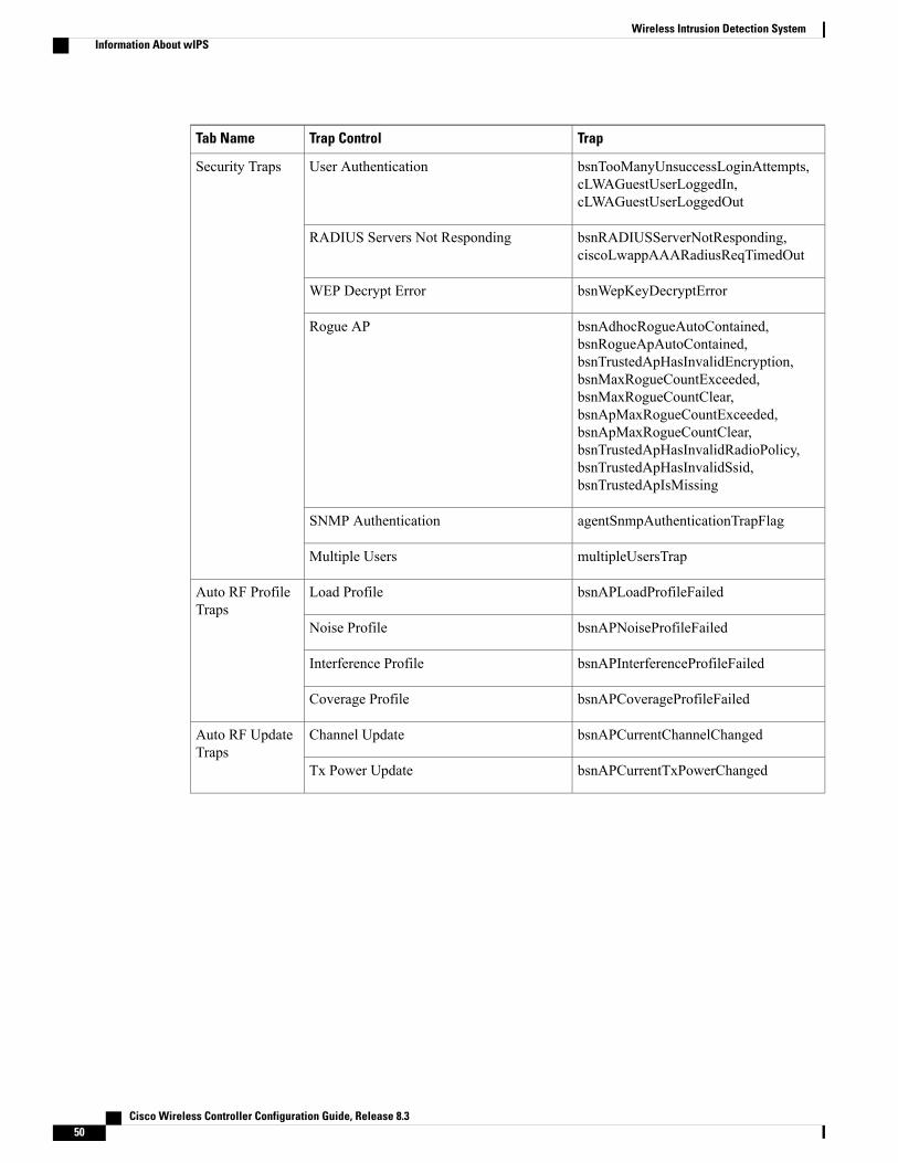
TrapTrap ControlTab Name
bsnTooManyUnsuccessLoginAttempts,cLWAGuestUserLoggedIn,cLWAGuestUserLoggedOut
User AuthenticationSecurity Traps
bsnRADIUSServerNotResponding,ciscoLwappAAARadiusReqTimedOut
RADIUS Servers Not Responding
bsnWepKeyDecryptErrorWEP Decrypt Error
bsnAdhocRogueAutoContained,bsnRogueApAutoContained,bsnTrustedApHasInvalidEncryption,bsnMaxRogueCountExceeded,bsnMaxRogueCountClear,bsnApMaxRogueCountExceeded,bsnApMaxRogueCountClear,bsnTrustedApHasInvalidRadioPolicy,bsnTrustedApHasInvalidSsid,bsnTrustedApIsMissing
Rogue AP
agentSnmpAuthenticationTrapFlagSNMP Authentication
multipleUsersTrapMultiple Users
bsnAPLoadProfileFailedLoad ProfileAuto RF ProfileTraps
bsnAPNoiseProfileFailedNoise Profile
bsnAPInterferenceProfileFailedInterference Profile
bsnAPCoverageProfileFailedCoverage Profile
bsnAPCurrentChannelChangedChannel UpdateAuto RF UpdateTraps
bsnAPCurrentTxPowerChangedTx Power Update
Cisco Wireless Controller Configuration Guide, Release 8.350
Wireless Intrusion Detection SystemInformation About wIPS

TrapTrap ControlTab Name
ciscoLwappMeshChildExcludedParentChild Excluded ParentMesh Traps
ciscoLwappMeshParentChangeParent Change
ciscoLwappMeshAuthorizationFailureAuthfailure Mesh
ciscoLwappMeshChildMovedChild Moved
ciscoLwappMeshExcessiveParentChangeExcessive Parent Change
ciscoLwappMeshExcessiveChildrenExcessive Children
ciscoLwappMeshAbateSNR,ciscoLwappMeshOnsetSNR
Poor SNR
ciscoLwappMeshConsoleLoginConsole Login
ciscoLwappMeshExcessiveAssociationExcessive Association
ciscoLwappMeshDefaultBridgeGroupNameDefault Bridge Group Name
The following are the trap descriptions for the traps mentioned in the SNMP Trap Controls and Their RespectiveTraps table:
• General Traps
◦SNMP Authentication—The SNMPv2 entity has received a protocol message that is not properlyauthenticated.
When a user who is configured in SNMP V3 mode tries to access the Cisco WLC withan incorrect password, the authentication fails and a failure message is displayed.However, no trap logs are generated for the authentication failure.
Note
◦Link (Port) Up/Down—Link changes status from up or down.
◦Link (Port) Up/Down—Link changes status from up or down.
◦Multiple Users—Two users log in with the same ID.
◦Rogue AP—Whenever a rogue access point is detected, this trap is sent with its MAC address;when a rogue access point that was detected earlier no longer exists, this trap is sent.
◦Config Save—Notification that is sent when the Cisco WLC configuration is modified.
• Cisco AP Traps
◦AP Register—Notification sent when an access point associates or disassociates with the CiscoWLC.
Cisco Wireless Controller Configuration Guide, Release 8.3 51
Wireless Intrusion Detection SystemInformation About wIPS

◦AP Interface Up/Down—Notification sent when an access point interface (802.11X) status goesup or down.
• Client-Related Traps
◦802.11 Association—Associate notification that is sent when a client sends an association frame.
◦802.11 Disassociation—Disassociate notification that is sent when a client sends a disassociationframe.
◦802.11 Deauthentication—Deauthenticate notification that is sent when a client sends adeauthentication frame.
◦802.11 Failed Authentication—Authenticate failure notification that is sent when a client sendsan authentication frame with a status code other than successful.
◦802.11 Failed Association—Associate failure notification that is sent when the client sends anassociation frame with a status code other than successful.
◦Exclusion—Associate failure notification that is sent when a client is exclusion listed (blacklisted).
The maximum number of static blacklist entries that the APs can have is 340.Note
◦Authentication—Authentication notification that is sent when a client is successfully authenticated.
◦Max Clients Limit Reached—Notification that is sent when the maximum number of clients,defined in the Threshold field, are associated with the Cisco WLC.
◦NAC Alert—Alert that is sent when a client joins an SNMP NAC-enabled WLAN.
This notification is generatedwhen a client on NAC-enabled SSIDs completes Layer2 authenticationto inform the NAC appliance about the client's presence. cldcClientWlanProfileName representsthe profile name of theWLAN that the 802.11 wireless client is connected to, cldcClientIPAddressrepresents the unique IP address of the client. cldcApMacAddress represents the MAC address ofthe AP to which the client is associated. cldcClientQuarantineVLAN represents the quarantineVLAN for the client. cldcClientAccessVLAN represents the access VLAN for the client.
◦Association with Stats—Associate notification that is sent with data statistics when a client isassociated with the Cisco WLC, or roams. Data statistics include transmitted and received bytesand packets.
◦Disassociation with Stats—Disassociate notification that is sent with data statistics when a clientdisassociates from the Cisco WLC. Data statistics include transmitted and received bytes andpackets, SSID, and session ID.
When you downgrade to Release 7.4 from a later release, if a trap that was not supportedin Release 7.4 (for example, NAC Alert trap) is enabled before the downgrade, all trapsare disabled. After the downgrade, you must enable all the traps that were enabled beforethe downgrade. We recommend that you disable the new traps before the downgradeso that all the other traps are not disabled.
Note
• Security Traps
Cisco Wireless Controller Configuration Guide, Release 8.352
Wireless Intrusion Detection SystemInformation About wIPS
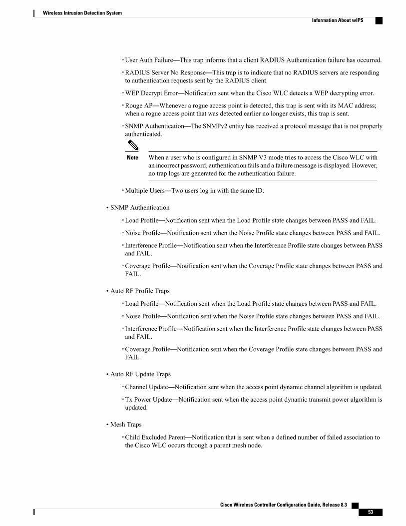
User Auth Failure—This trap informs that a client RADIUS Authentication failure has occurred.◦
◦RADIUS Server No Response—This trap is to indicate that no RADIUS servers are respondingto authentication requests sent by the RADIUS client.
◦WEP Decrypt Error—Notification sent when the Cisco WLC detects a WEP decrypting error.
◦Rouge AP—Whenever a rogue access point is detected, this trap is sent with its MAC address;when a rogue access point that was detected earlier no longer exists, this trap is sent.
◦SNMP Authentication—The SNMPv2 entity has received a protocol message that is not properlyauthenticated.
When a user who is configured in SNMP V3 mode tries to access the Cisco WLC withan incorrect password, authentication fails and a failure message is displayed. However,no trap logs are generated for the authentication failure.
Note
◦Multiple Users—Two users log in with the same ID.
• SNMP Authentication
◦Load Profile—Notification sent when the Load Profile state changes between PASS and FAIL.
◦Noise Profile—Notification sent when the Noise Profile state changes between PASS and FAIL.
◦Interference Profile—Notification sent when the Interference Profile state changes between PASSand FAIL.
◦Coverage Profile—Notification sent when the Coverage Profile state changes between PASS andFAIL.
• Auto RF Profile Traps
◦Load Profile—Notification sent when the Load Profile state changes between PASS and FAIL.
◦Noise Profile—Notification sent when the Noise Profile state changes between PASS and FAIL.
◦Interference Profile—Notification sent when the Interference Profile state changes between PASSand FAIL.
◦Coverage Profile—Notification sent when the Coverage Profile state changes between PASS andFAIL.
• Auto RF Update Traps
◦Channel Update—Notification sent when the access point dynamic channel algorithm is updated.
◦Tx Power Update—Notification sent when the access point dynamic transmit power algorithm isupdated.
• Mesh Traps
◦Child Excluded Parent—Notification that is sent when a defined number of failed association tothe Cisco WLC occurs through a parent mesh node.
Cisco Wireless Controller Configuration Guide, Release 8.3 53
Wireless Intrusion Detection SystemInformation About wIPS

◦Notification sent when a child mesh node exceeds the threshold limit of the number of discoveryresponse timeouts. The child mesh node does not try to associate an excluded parent mesh nodefor the interval defined. The child mesh node remembers the excluded parent MAC address whenit joins the network, and informs the Cisco WLC.
◦Parent Change—Notification is sent by the agent when a child mesh node changes its parent. Thechild mesh node remembers previous parent and informs the Cisco WLC about the change ofparent when it rejoins the network.
◦Child Moved—Notification sent when a parent mesh node loses connection with its child meshnode.
◦Excessive Parent Change—Notification sent when the childmesh node changes its parent frequently.Each mesh node keeps a count of the number of parent changes in a fixed time. If it exceeds thedefined threshold, the child mesh node informs the Cisco WLC.
◦Excessive Children—Notification sent when the child count exceeds for a RAP and a MAP.
◦Poor SNR—Notification sent when the child mesh node detects a lower SNR on a backhaul link.For the other trap, a notification is sent to clear a notification when the child mesh node detects anSNR on a backhaul link that is higher then the object defined by 'clMeshSNRThresholdAbate'.
◦Console Login—Notification is sent by the agent when a login on aMAP console is either successfulor fail after three attempts.
◦Default Bridge Group Name—Notification sent when the MAP mesh node joins its parent usingthe default bridge group name.
The remaining traps do not have trap controls. These traps are not generated too frequently and do notrequire any trap control. Any other trap that is generated by the Cisco WLC cannot be turned off.
Note
In all of the above cases, the Cisco WLC functions solely as a forwarding device.Note
wIPS Support for 40 and 80 MHz
Release 8.2 introduces wIPS support for 40 and 80 MHz range. This feature detects alarms in the 40 and 80MHz range (if RRM channel scanning is selected) and provides information to the Cisco Prime Infrastructure.The channel-width information is derived from the packet data rate and sent to the wIPS module that storesthe channel width per alarm. Using the show capwap am alarm alarm-id command, you can view the channelwidth in which the attack has occured.
The wIPS alarm report contains the channel-width of the attack and device capability (11a/bg/n/ac). No wIPSspecific configuration is required to enable this feature. The only prerequisite is that RRM scanning shouldbe enabled for this feature to work properly.
Restrictions for wIPS• wIPS ELM is not supported on the following APs:
Cisco Wireless Controller Configuration Guide, Release 8.354
Wireless Intrusion Detection SystemRestrictions for wIPS

◦702i
◦702W
◦1130
◦1240
• Request to Send (RTS) and Clear to Send (CTS) frames are not forwarded to driver if RTS and CTS arefor the BSSID of the AP.
•WIPS and Rogue Detection must be disabled on the AP in IPv6 mode to prevent it from leaking trafficoutside CAPWAP towards 32.x.x.x destination.
Configuring wIPS on an Access Point (GUI)
Step 1 ChooseWireless > Access Points > All APs > access point name.Step 2 Set the AP Mode parameter. To configure an access point for wIPS, you must choose one of the following modes from
the AP Mode drop-down list:
• Local
• FlexConnect
• Monitor
Step 3 Choose wIPS from the AP Sub Mode drop-down list.Step 4 Click Apply.Step 5 Click Save Configuration.
Configuring wIPS on an Access Point (CLI)
Step 1 Configure an access point for the monitor mode by entering this command:config ap mode {monitor | local | flexconnect} Cisco_AP
To configure an access point for wIPS, the access point must be inmonitor, local, or flexconnectmodes.Note
Step 2 Enter Y when you see the message that the access point will be rebooted if you want to continue.Step 3 Save your changes by entering this command:
save config
Step 4 Disable the access point radio by entering this command:config {802.11a | 802.11b} disable Cisco_AP
Step 5 Configure the wIPS submode on the access point by entering this command:config ap mode ap_mode submode wips Cisco_AP
Cisco Wireless Controller Configuration Guide, Release 8.3 55
Wireless Intrusion Detection SystemConfiguring wIPS on an Access Point (GUI)

To disable wIPS on the access point, enter the config apmode ap_mode submode noneCisco_AP command.Note
Step 6 Enable wIPS-optimized channel scanning for the access point by entering this command:config ap monitor-mode wips-optimized Cisco_AP
The access point scans each channel for 250 milliseconds. It derives the list of channels to be scanned from the monitorconfiguration. You can choose one of these options:
• All—All channels are supported by the access point’s radio
• Country—Only the channels supported by the access point’s country of operation
• DCA—Only the channel set used by the dynamic channel assignment (DCA) algorithm, which, by default, includesall of the nonoverlapping channels allowed in the access point’s country of operation
The 802.11a or 802.11bMonitor Channels information in the output of the show advanced {802.11a | 802.11b}monitorcommand shows the monitor configuration channel set:
Default 802.11b AP monitoring802.11b Monitor Mode........................... enable802.11b Monitor Channels....................... Country channels802.11b AP Coverage Interval................... 180 seconds802.11b AP Load Interval....................... 60 seconds802.11b AP Noise Interval...................... 180 seconds802.11b AP Signal Strength Interval............ 60 seconds
Step 7 Reenable the access point radio by entering this command:config { 802.11a | 802.11b} enable Cisco_AP
Step 8 Save your changes by entering this command:save config
Viewing wIPS Information (CLI)
You can also view the access point submode from the controller GUI. To do so, chooseWireless >AccessPoints > All APs > access point name > the Advanced tab. The AP Sub Mode field shows wIPS if theaccess point is in the monitor mode and the wIPS submode is configured on the access point, or None ifthe access point is not in the monitor mode or the access point is in the monitor mode, but the wIPSsubmode is not configured.
Note
• See the wIPS submode in the access point by entering this command:show ap config general Cisco_AP
• See the wIPS-optimized channel-scanning configuration in the access point by entering this command:show ap monitor-mode summary
• See the wIPS configuration forwarded by Cisco Prime Infrastructure to the controller by entering thiscommand:
Cisco Wireless Controller Configuration Guide, Release 8.356
Wireless Intrusion Detection SystemViewing wIPS Information (CLI)

show wps wips summary
• See the current state of the wIPS operation in the controller by entering this command:show wps wips statistics
• Clear the wIPS statistics in the controller by entering this command:clear stats wps wips
Cisco Adaptive wIPS AlarmsThe controller supports five Cisco Adaptive wIPS alarms that serve as notifications for potential threats. Youmust enable these alarms based on your network topology using Cisco Prime Infrastructure. For more detailson this, see the Cisco Prime Infrastructure User Guide.
• Device not protected by VPN—The controller generates an alarm when a wireless client and accesspoint does not communicate over secure VPN, as all controller traffic must be routed through a VPNconnection.
•WPA Dictionary Attack—The controller generates an alarm when a dictionary attack on the WPAsecurity key occurs. The attack is detected before the initial handshake message between the client andthe access point.
•WiFi Direct Session Detected—The controller generates an alarm when Wifi direct sessions of clientsare detected with Wifi direct and prevents enterprise vulnerability.
• RSN Info Element Out-of-Bound Denial-of-Service—The controller generates an alarm when there arelarge values for RSN information element that results in an access point crash.
• DS Parameter Set DoS—The controller generates an alarm when confusion exists in the channel for theclient while multiple channels overlap.
Cisco Wireless Controller Configuration Guide, Release 8.3 57
Wireless Intrusion Detection SystemCisco Adaptive wIPS Alarms

Cisco Wireless Controller Configuration Guide, Release 8.358
Wireless Intrusion Detection SystemCisco Adaptive wIPS Alarms