wireless communication at tata steel
DESCRIPTION
This project is based on the study of the wireless communication and its maintenance in Tata Steel. In the MED dept. of Tata Steel I have studied the maintenance and fault diagnostics methodology in Motorola wireless set. Tata Steel uses Motorola W/T sets. Currently GP 338/328 is used for handheld sets and GM-338 is used for Static Sets.TRANSCRIPT

1
PROJECT REPORT FOR VOCATIONAL TRAINING AT TATA STEEL
GUIDED BY :MR. ARUN KUMAR SINGHMED ( ELECTRICAL),TATA STEEL.
SUBMITTED BY :ANKIT AGARWALVT NO. : VT20140255ELECTRONICS AND TELECOMMUNICATION

2
PROJECT REPORT ON “ STUDY OF WIRELESS
COMMUNICATION USED AT TATA STEEL AND ITS MAINTENANCE PRACTICE ADOPTED AT ELR , MED (ELECT.) ”UNDER THE GUIDANCE OF :
MR . ARUN KUMAR SINGH MED( ELECTRICAL).FROM 6TH MAY, 2014 TO 24th JUNE,2014
3
This is to certify that ANKIT AGARWAL(B.Tech, 5th Sem.) of C.V.RAMAN COLLEGE OF ENGG. (BBS), have undergone their vocational training at TATA STEEL Ltd. from Maintenance Engineering Dept.(Electrical) for a period of seven weeks (49 days) from MAY 06th,2014 to JUNE 24th,2014. We are glad to mention that they carried out their project on “TO STUDY WIRELESS COMMUNICATION USED AT TATA STEEL AND ITS MAINTENANCE PRACTICE ADOPTED AT ELR, MED(ELECT.)” , very sincerely under the guidance of the mentioned guide. During their training period, they have been found to be well disciplined, hard working, obedient and keen to learn the things. We wish them great success in their forthcoming careers.
CERTIFICATE
MR . ARUN KUMAR SINGH, PROJECT GUIDE,MED (ELCET.)

4
First of all, I would like to extend my heartfelt gratitude to all the people at TATA STEEL Ltd., who have helped and guided us for successfully completing the project and thoroughly understanding the concepts. I am thankful to “TATA STEEL”. For giving me the opportunity to carry out this project in its organization. I would like to thank Chief/Head of MED (electrical) Dept. for providing me the golden opportunity to carry out my project under the esteemed guidance of Mr. Arun Kumar Singh (Foreman), my Respected Project Head. It is a matter of great privilege to express our sincere gratitude to Mr.ARUN KUMAR SINGH, MED (ELECTRICAL) for giving me opportunity to work in this department. I am grateful to Mr.RANJIT BHATTACHARJEE (Technical Assistant), for giving me Sufficient information to work on this project. This project helps us a lot to learn about the Wireless Communication and its set up. The whole training period was interesting & knowledgeable. The things, which we have learned from here, would be helpful to us in the coming years. The affection & care given to us is boundless. I thank each & everyone in MED (Elect.) for enriching us with knowledge & boosting our knowledge about the industrial wireless communication.
ACKNOWLEDGEMENT
The time, which I spent in TATA STEEL (JAMSHEDPUR) during training, was a wonderful experience in itself and I would like to thank all of those who directly and indirectly assisted to accomplish this project successfully and adequately.
THANKING YOU,ANKIT AGARWAL.
5
ENTERY

6
This project is based on the study of the wireless communication and its maintance in Tata Steel. In the MED dept. of Tata Steel I have studied the maintenance and fault diagnostics methodology in Motorola wireless set. Wireless Communication is the transfer of information over a distance without the use of electrical conductors or wires. The distance involved may be short (a few meters as in television remote control) or long(thousands or millions of kilometers for radio communications). When the context is clear, the term is often shortened to “wireless”. Wireless communications is generally considered to be a branch of “telecommunications”.
ABOUT PROJECT…….

7
The term wireless is commonly used in the telecommunications industry to refer to telecommunications system(eg. Radio transmitters and receivers, remote controls, computer networks, network terminals etc.) which use some form of energy(eg. Radio frequency(RF), infrared light, laser light, visible light, acoustic energy etc. to transfer information without the use of wires information is transferred in this manner over both short and long distances. Application may involve point-to-point communication, point-to-multipoint communication, broadcasting, cellular networks and other wireless networks.
8
CONTENTS1. History Of TATA STEEL• Introduction• Mission of Tata steel• Vision of Tata steel• Empire of TATA STEEL• History Highlighted• The Beginning• Tata Steel Today• Tata Steel in The New Era• Awards Won
2. Safety• Safety Principles & Occupational
Health Policy• Safety(introduction) • Why Safety is must in industry • Causes of incidents and injuries • Safety guidelines for trainees • Emergency

9
3. Introduction To Maintenance Engineering Department (Electrical) • Introduction to the department • Different sections
Inspection Service & transmission E.D.M.S(Electrical Development & Maintenance
Shop & heavy winding shop) Crane Revamping Repair shop
4. Introduction To Wireless Communication And Its Principle • Introduction • Principle of Wireless communication • Types of Wireless communication
Infrared (IR) Wireless communication Broadcast radio Microwave Radio The Wireless Channel History of Wireless channel
10
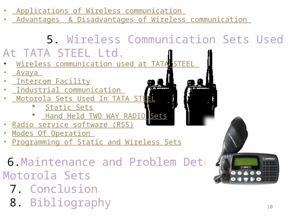
• Applications of Wireless communication • Advantages & Disadvantages of Wireless communication
5. Wireless Communication Sets Used At TATA STEEL Ltd.• Wireless communication used at TATA STEEL • Avaya • Intercom Facility• Industrial communication • Motorola Sets Used In TATA STEEL
Static Sets Hand Held TWO WAY RADIO Sets
• Radio service software (RSS)• Modes Of Operation • Programming of Static and Wireless Sets
6.Maintenance and Problem Detection Of Motorola Sets 7. Conclusion 8. Bibliography

11
ABOUT TATA
STEEL
12
Tata Steel formerly known as TISCO (Tata Iron and Steel Company Limited) is the world's sixth largest steel company, with an annual crude steel capacity of 31 million tones. It is the largest private sector steel company in India in terms of domestic production. Ranked 258th on Fortune Global 500, it is based in Jamshedpur, Jharkhand, India. It is part of Tata Group of companies. Tata Steel is also India's second-largest and second-most profitable company in private sector with consolidated revenues of Rs 1,32,110 crore and net profit of over Rs 12,350 crore during the year ended March 31, 2008.
INTRODUCTION

13
Its main plant is located in Jamshedpur, Jharkhand, with its recent acquisitions, the company has become a multinational with operations in various countries. The Jamshedpur plant contains the DCS supplied by Honeywell. The registered office of Tata Steel is in Mumbai. The company was also recognized as the world's best steel producer by World Steel Dynamics in 2005. The company is listed on Bombay Stock Exchange and National Stock Exchange of India, and employs about 82,700 people (as of 2007).

14
Consistent with the vision and values of the founder JAMSHEDJI TATA, Tata steel strives to strengthen India's industrial base through the effective utilization of staff and materials. The means envisaged to achieve this are high technology and productivity, consistent with modern management practices. TATA STEEL recognizes that while honesty and integrity are essential ingredients of a strong and stable enterprise , profitability provides the main spark for economic activity. Overall, the company seeks to scale the heights of excellence in as that it does in an atmosphere free from fear, and thereby reaffirms its faith in democratic values.
MISSION OF TATA STEEL

15
VISION OF TATA STEEL We aspire to be the global steel industry benchmark for value creation and corporate citizenship.
We make the difference through:
• Our PEOPLE, by fostering team work, nurturing talent, enhancing leadership capability and acting with pace, pride and passion.
• Our OFFER , by becoming the supplier of choice, delivering premium products and services and creating values with our customer.
• Our INNOVATIVE approach, by developing leading edge solutions in technology, process and products.
• Our CONDUCT, by providing a safe working place, respecting the environment, caring for our communities and demonstrating high ethical standard.

16
THE FOUNDER :
• Jamsetji Nusserwanji Tata ( 1839-1904 ) ranks among the greatest visionaries of Industrial enterprises of all time.
• Born on 3rd March, 1839 into a family descended from Parsi priests in Navsari, a center for age-old Parsi culture, he was educated at Elphinstone College, Bombay.
PIONEERS :• Sir Dorabji Tata (1859-1933): • J N Tata had exhorted to his sons to pursue
and develop his life’s work; his elder son, Dorab Tata carried out the bequest with scrupulous zeal, and distinction.
• Thus, even though it was Jamsetji Tata who had envisioned the mammoth projects, it was in fact Dorab Tata who actually brought the ventures to existence and fruition. He was the first Chairman of the gigantic Tata enterprises.
EMPIRE OF TATA STEEL
17
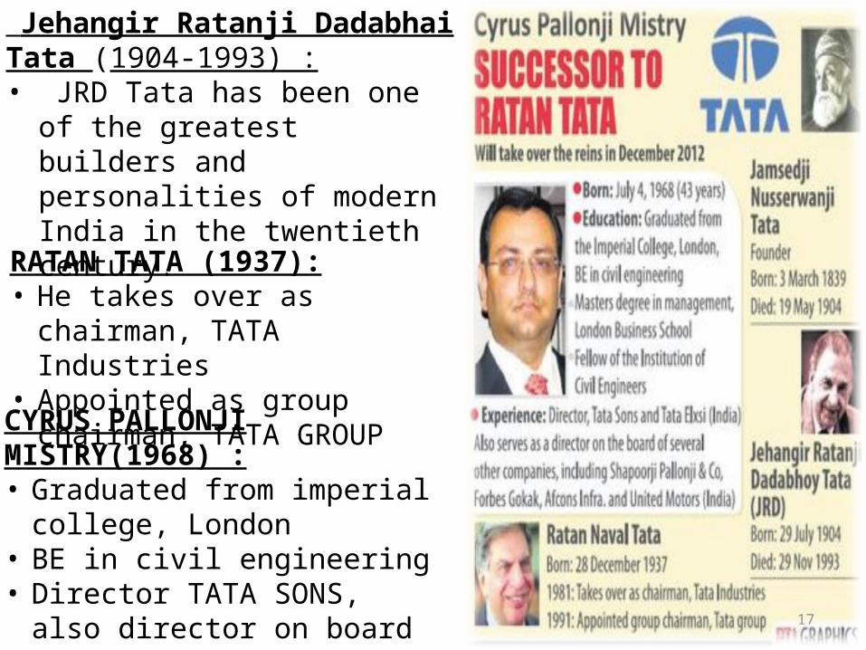
RATAN TATA (1937):• He takes over as chairman,
TATA Industries• Appointed as group
chairman, TATA GROUPCYRUS PALLONJI MISTRY(1968) :• Graduated from imperial
college, London• BE in civil engineering• Director TATA SONS, also
director on board of several companies Shapoorji Pallonji & co., Forbes Gokak, Afton Infra & United Motors(INDIA).
Jehangir Ratanji Dadabhai Tata (1904-1993) :• JRD Tata has been one of
the greatest builders and personalities of modern India in the twentieth century.

18
HISTORY HIGHLIGHTED….

19

20
21
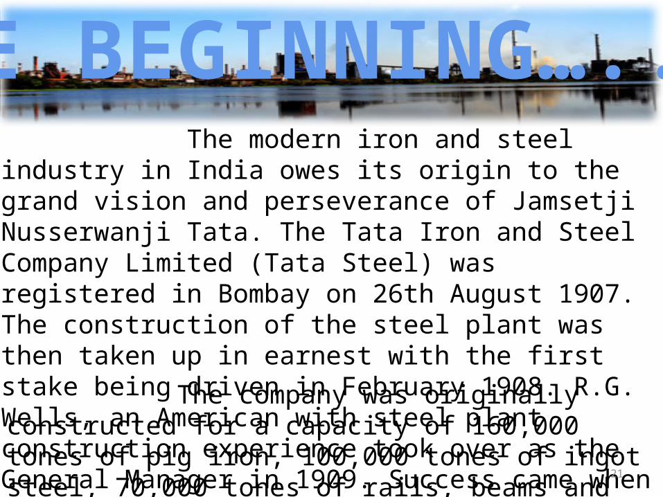
The modern iron and steel industry in India owes its origin to the grand vision and perseverance of Jamsetji Nusserwanji Tata. The Tata Iron and Steel Company Limited (Tata Steel) was registered in Bombay on 26th August 1907. The construction of the steel plant was then taken up in earnest with the first stake being driven in February 1908. R.G. Wells, an American with steel plant construction experience took over as the General Manager in 1909. Success came when the first blast furnace was blown-in on 2nd December 1911, and the first ingot rolled on 16th February 1912.
The company was originally constructed for a capacity of 160,000 tones of pig iron, 100,000 tones of ingot steel, 70,000 tones of rails, beams and shapes, and 20,000 tones of bars, hoops and rods
THE BEGINNING…..
22
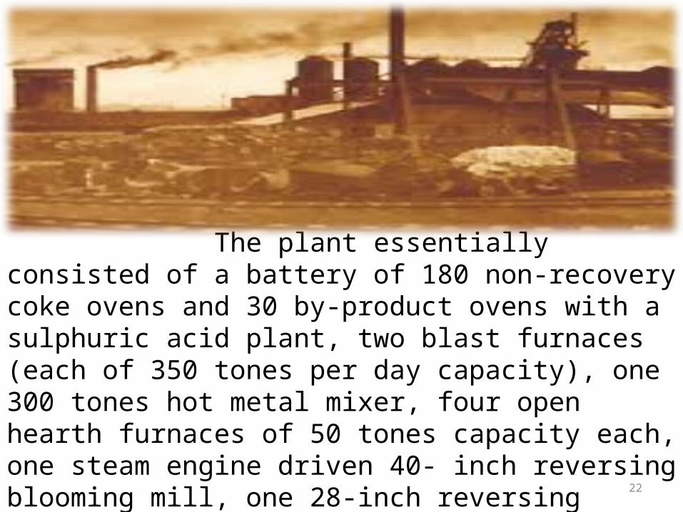
The plant essentially consisted of a battery of 180 non-recovery coke ovens and 30 by-product ovens with a sulphuric acid plant, two blast furnaces (each of 350 tones per day capacity), one 300 tones hot metal mixer, four open hearth furnaces of 50 tones capacity each, one steam engine driven 40- inch reversing blooming mill, one 28-inch reversing combination rail and structural mill with re-heating furnaces, and one 16- inch and two 10-inch rolling mills. Besides, the steel works had a power house, auxiliary facilities and a well equipped laboratory. The cost of the plant as erected came to around Rs.23 million.

23

24
As a result of innovations and technological up gradation, Tata Steel, has become a well-run ultra modern plant - one of the best in the world. Fundamental changes in some metallurgical parameters have brought about this remarkable transformation. Necessity became the mother of invention and numerous innovations invoked improvement.The metallurgical changes introduced were essentially centered around:• Reducing alumina level
in sinter from 4.4 to 2.5 %.
• Improving in coke quality
TATA STEEL TODAY

25
• Making changes in the fluxes used in sinter making essentially to decrease the alkali input.
• Adopting the optimum LD vessel configuration and blowing conditions to accommodate the high slag volume required to deal with high silicon and phosphorus in Indian hot metal.
• Increasing the yield during LD steelmaking.
• All these factors have made Tata Steel internationally cost competitive. In terms of hot metal costs, Tata Steel is amongst the lowest in the world and has a clear advantage over other major integrated producers. The cost of conversion from hot metal to a finished product such as hot rolled coils where Tata Steel has not been very competitive so far would be taken care of in the near future as investments already made to achieve the results foreseen.
• High ash in coke, poor room temperature and high temperature strengths of coke, high alumina in the iron oxide feed, high silicon in hot metal, low yields during steelmaking, low yield of finished products, high energy consumption, high manpower, etc. have been the weaknesses not only of Tata Steel but of the Indian Steel industry.

26
Tata Steel is all set to establish itself as the supplier of choice by delighting all its customers with its products and services. The Organization is envisaged to become the most cost competitive Steel plant to serve the community and the nation. Where Tata Steel would venture, others will follow. The 21st century will certainly see a new Tata Steel - an integrated Steel plant in India with truly world class facilities along with a will to win amongst a committed and streamlined workforce.
THE NEW ERA..

27
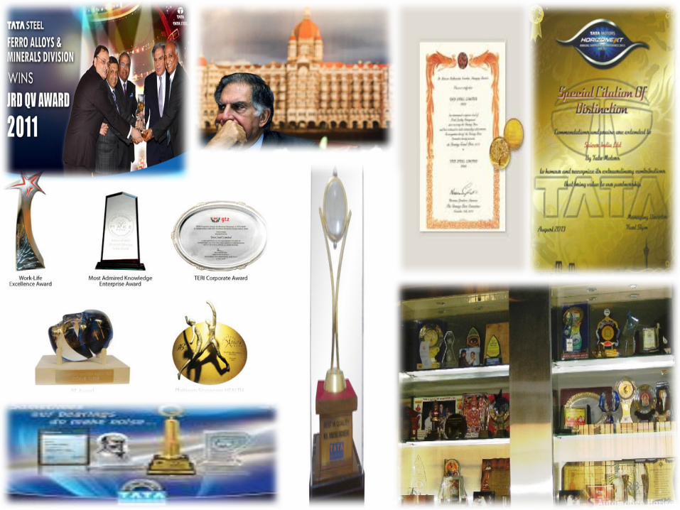
Tata Steel India was awarded the Deming Application Prize 2008 for Excellence in Total Quality Management. It is the 1st integrated steel company in the world, outside Japan to get this award.
Tata Steel Works has been conferred the prestigious social accountability (SA) 8000 certification by SAI, USA.
It has been awarded Asia’s Most Admired Knowledge Enterprise award 5 times in 2003,2004,200,2007,2008.
Best governed company award 2006 for setting high standards in governance practices.
World Steel Dynamics has ranked Tata Steel as the world’s best steel makers (for 2 consecutive years) in its annual listing in February 2006.
Tata Steel has been conferred the Prime Minister of India ‘s Trophy for the Best Integrated Steel plant 5 times.
AWARDS !!!!
28

29
SAFETY AT TATA STEEL FOR TRAINEES
30
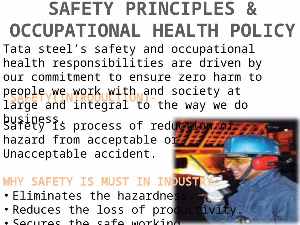
SAFETY(INTRODUCTION)- Safety is process of reduction of hazard from acceptable or Unacceptable accident. WHY SAFETY IS MUST IN INDUSTRY- • Eliminates the hazardness. • Reduces the loss of productivity. • Secures the safe working. • Reduces the property losses.
SAFETY PRINCIPLES & OCCUPATIONAL HEALTH POLICY
Tata steel’s safety and occupational health responsibilities are driven by our commitment to ensure zero harm to people we work with and society at large and integral to the way we do business.

31
CAUSES OF INCIDENTS & INJURIES- • UNSAFE CONDITIONS –
4% • UNSAFE ACTS – 96%
EMERGENCY- • Do not light fire, matches, etc.
where there is flammables around. • In case of any injury/sickness, report
to our hospital casualty.
Safety Principles-• Safety is a line management
responsibility.• All injuries can be prevented.• Felt concern and care for the
employee on “ 24 hours safety” shall be demonstrated by leaders.
• Working safety shall be condition of employment.
• Every job shall be assessed for risk involved and shall be carried out as per authorized procedures/checklist/necessary work permit and using necessary personal protection equipment.

32
SAFETY GUIDELINES FOR TRAINEES GENERAL- You must undergo “safety induction” at our safety deptt for
the specific area, you wish to undertake training. Must use safety shoe, safety helmet, other safety
appliances as per job requirement, inside the work. Smoking inside works is strictly prohibited. No tobacco
pouch/other plastic/pouch to be brought inside works. Do not loiter inside the plant. Be restricted to your place of
training. On the shop floor ,restrict your movement to the gangway,
marked in green, except when you have to go to some offices or your assigned work site.
Entry to the following area is restricted unless authorized by concerned head of deptt.
All electl. Control room. All process, electl basement. EOT Crane, crane gantry,etc. High voltage area/ Transformer area. Any confined space. At the top of any building/ roof, etc. High noise area, without earmuff. Any moving part of M/C. or equipment. If by any omission or commission you cause damage/ loss
to Co’s property, your training will be terminated immediately and no certificate will be issued .
33
INTRODUCTION TO MAINTENANCE ENGG. DEPARTMENT (ELECTRICAL)

34
Introduction to the department:
Maintenance Engineering Department (Electrical) came into ex- instance in May 2001, after the reorganization process in Tata Steel. In the new formed department Central Maintenance Section, Development Section and Instrumentation Section of Electronics department and General Testing Section and Relay Testing Section of Electrical Power (G&D) department were merged with Electrical Services Department.
Its main functions are Electronics & Electrical Development ; repair of electronics items and cards ; repair / overhaul / calibration process equipment , recording instruments , smart sensors & transducers, reconditioning of all ranges of control valves and actuators ; repair & calibration of electrical machines ; conversion of motor to BLUE-LINE ; relay testing ; general testing for electrical power systems ; transformer repair; transmission system maintenance ; revamping of all cranes. MED (Electrical) also includes the newly created Electrical Field Task Group. The department is under Shared Services Cost Centre. The key objective of this department is to provide engineering services to various departments.
35
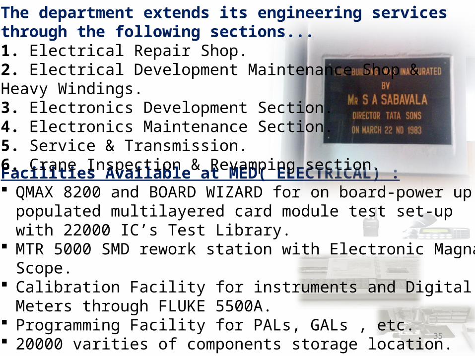
Facilities Available at MED( ELECTRICAL) : QMAX 8200 and BOARD WIZARD for on board-power up
populated multilayered card module test set-up with 22000 IC’s Test Library.
MTR 5000 SMD rework station with Electronic Magna Scope.
Calibration Facility for instruments and Digital Meters through FLUKE 5500A.
Programming Facility for PALs, GALs , etc. 20000 varities of components storage location. Computerized Universal Calibration Test Bench. Fast diagnosis of faults, repair facility and Tuning of
wireless sets. Office Intercom and Electronic Exchange Maintenance.
The department extends its engineering services through the following sections... 1. Electrical Repair Shop. 2. Electrical Development Maintenance Shop & Heavy Windings. 3. Electronics Development Section. 4. Electronics Maintenance Section. 5. Service & Transmission. 6. Crane Inspection & Revamping section.

36
Different sections which comes under the department: 1. Inspection: This section carries the routine Inspection of following a) Electrical Substation b) Cable Tunnel c) Telephone Booth d) Critical Blue Line Motors e) Crane.
2. Service & transmission: The key objective of S&T is to provide Engineering Services to various departments of TISCO Works & Other Associated Companies. The Service & Transmission handles a large no of work orders raised by various customer departments every year. Focus Area of Activities:- • Repair / Maintenance of Cables, Overhead lines, Sub-Stations. • illumination of General Area Roads, Yards & Office lighting 3. E.D.M.S(Electrical Development & Maintenance Shop & heavy winding shop): This shop was started on 14.04.1975 for the development and manufacture of following items: • Armature Coils. • H.T. Stator Coils. • Field Coils. • Probe Coils. • Rotor Coils.

37
4. Crane revamping: CRC came into existence in 1972 under Chief Electrical Engineer. Later on it was attached with Electrical Services as a section and at present it is one of the sections at MED (Electrical) Dept. • Idea behind formation of CRC was to
revamp the old cranes with chronic problems and to add new life with improved performance and availability by spending few lakhs of rupees. CRC started its first activity in 1972 and continued its journey. Till March 2001 it has revamped 194 numbers of cranes and lifts.
• During revamping activity, lot of improvements, modifications and innovative ideas have been incorporated and established its identity. In general CRC handles
• SRB scheme only but on special case, it executes work order job also. Other than revamping CRC rendered its service during breakdown also.
5. Repair shop: Defective electrical motors come here for repairing and rectification and overhauling. Electrical maintenance shop is one of the most important sections of MED (Electrical) dept. The job of electrical repair shop is to repair various kinds of electrical motors, man coolers changing sets and manufacturing panels for cranes. The ERS is divided into several sections for efficiency and safety.

38
MED(ELEC) KNOWLEDGE CENTER
ELR REPAIR UNIT
MED
(ELEC
T.) LAYO
UT
MED
(ELEC
T.) LAYO
UT
39
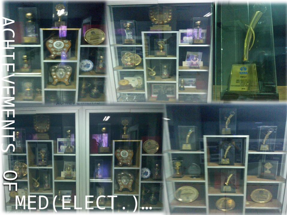
AC
HIE
VEM
EN
TS
OF
MED(ELECT.)…

40
INTRODUCTION TO WIRELESS COMMUNICATION & IT’S PRINCIPLE

41
INTRODUCTION Wireless communication is the
transfer of information over a distance without the use of electrical conductors or "wires". The distances involved may be short (a few meters as in television remote control) or long (thousands or millions of kilometers for radio communications). Wireless communication is generally considered to be a branch of telecommunications. Past decade has seen a surge of research activities in the field of wireless communication. Emerging from this research thrust are new points of view on how to communicate effectively over wireless channels. The goal of this course is to study in a unified way the fundamentals as well as the new research developments. The concepts are illustrated using examples from several modern wireless systems (GSM, IS-95, CDMA 2000 1x EV-DO, Flarion's Flash OFDM, ArrayComm systems.) It encompasses various types of fixed, mobile, and portable two- way radios, cellular telephones, personal digital assistants (PDAs), and wireless networking. Other examples of wireless technology include GPS units, garage door openers and or garage doors, wireless computer mice, keyboards and headsets, satellite television and cordless telephones. Wireless operations permits services, such as long-range communications, that are impossible or impractical to implement with the use of wires.
42
The term is commonly used in the telecommunications industry to refer to telecommunications systems (e.g. radio transmitters and receivers, remote controls, computer networks, network terminals, etc.) which use some form of energy (e.g. radio frequency (RF), infrared light, laser light, visible light, acoustic energy, etc.) to transfer information without the use of wires. Information is transferred in this manner over both short and long distances.
In 1895, Guglielmo Marconi opened the way for modern wireless communications by transmitting the three-dot Morse code for the letter ‘S’ over a distance of three kilometers using electromagnetic waves. From this beginning, wireless communications has developed into a key element of modern society. From satellite transmission, radio and television broadcasting to the now ubiquitous mobile telephone, wireless communications has revolutionized the way societies function.
Wireless communications and the economic goods and services that utilize it have some special characteristics that have motivated specialized studies. First, wireless communications relies on a scarce resource – namely, radio spectrum. Second, use of spectrum for wireless communications required the development of key complementary technologies; especially those that allowed higher frequencies to be utilised more efficiently. Finally, because of its special nature, the efficient use of spectrum required the coordinated development of standards. Those standards in turn played a critical role in the diffusion of technologies that relied on spectrum use.

43
PRINCIPLE OF COMMUNICATION Wireless communications begin with a message that is converted into an electronic signal by a device called a transmitter. There are two types of transmitters: analog and digital. An analog transmitter sends electronic signals as modulated radio waves. The analog transmitter modulates the radio wave to carry the electronic signal and then sends the modified radio signal through space. A digital transmitter encodes electronic signals by converting messages into a binary code, the series of zeros and ones that are the basis of all computer programming. The encoded electronic signal is then sent as a radio wave. Devices known as receivers decode or demodulate the radio waves and reproduce the original message over a speaker. Wireless communications systems involve either one-way transmissions, in which a person merely receives notice of a message, or two-way transmissions, such as a telephone conversation between two people.

44
An example of a device that only receives one-way transmission is a pager, which is a high- frequency radio receiver. When a person dials a pager number, the pager company sends a radio signal to the desired pager. The encoded signal triggers the pager’s circuitry and notifies the customer carrying the pager of the incoming call with a tone or a vibration, and often the telephone number of the caller. Advanced pagers can display short messages from the caller, or provide news updates or sports scores. Two-way transmissions require both a transmitter and a receiver for sending and receiving signals. A device that functions as both a transmitter and a receiver is called a transceiver. Cellular radio telephones and two-way radios use transceivers, so that back-and-forth communication between two people can be maintained. Early transceivers were very large, but they have decreased in size due to advances in technology. Fixed-base transceivers, such as those used at police stations, can fit on a desktop, and hand-held transceivers have shrunk in size as well. Several current models of handheld transceivers weigh less than 0.2 kg (0.5 lb). Some pagers also use transceivers to provide limited response options. These brief return-communication opportunities allow paging users to acknowledge reception of a page and to respond using a limited menu of options.

45
In electronics and telecommunications a transmitter or radio transmitter is an electronic device which, with the aid of an antenna, produces radio waves. The transmitter itself generates a radio frequency alternating current, which is applied to the antenna. When excited by this alternating current, the antenna radiates radio waves. In addition to their use in broadcasting, transmitters are necessary component parts of many electronic devices that communicate by radio, such as cell phones, wireless computer networks,Bluetooth enabled devices, garage door openers, two-way radios in aircraft, ships, and spacecraft, radar sets, and navigational beacons.
TRANSMITTER

46
RECEIVER
An RF Receiver module receives the modulated RF signal, and demodulates it. Super-regenerative modules are usually low cost and low power designs using a series of amplifiers to extract modulated data from a carrier wave. Super-regenerative modules are generally imprecise as their frequency of operation varies considerably with temperature and power supply voltage.Superheterodyne receivers offer increased accuracy and stability over a large voltage and temperature range. This stability comes from a fixed crystal design which in turn leads to a comparatively more expensive product

47
TYPES OF COMMUNICATION The different types of wireless communication technologies include:
1.Infrared (IR) wireless communication- IR wireless communication communicates data or information in devices or systems through infrared (IR) radiation. Infrared is electromagnetic energy at a wavelength that is longer than that of red light.
Working: IR wireless is used for short and medium-range communications and security control. For IR communication to work, the systems mostly operate in line-of-sight mode which means that there must be no obstruction between the transmitter (source) and receiver (destination). Infrared is used in television remote controls and security systems. In the electromagnetic spectrum, infrared radiation lies between microwaves and visible light, therefore, they can be used as a source of communication.
Working of Infrared Wireless Communication:A photo LED transmitter and a photodiode receptor are required for successful IR communication.The LED transmitter transmits the infrared signal in the form of non-visible light, which is captured and retrieved as information by the photo receptor. In this way, the information between the source and the target is transferred.

48
2.Broadcast Radio communication-
Basically an audio broadcasting service, radio broadcasts sound through the air as radio waves. It uses a transmitter to transmit radio waves to a receiving antenna. To broadcast common programming, stations are linked to the radio networks.The broadcast occurs either in syndication or simulcast (simultaneous broadcast) or both. Radio broadcasting can also be done via cable FM, the internet and satellites. A radio broadcast sends data over long distances (across countries) at up to 2 megabits per second (AM/FM Radio). What is Broadcast Radio Working:Radio waves are electromagnetic signals transmitted by an antenna. Radio waves have different frequency segments, and you will be able to pick up an audio signal by tuning into a specific frequency segment.
In computer networking and telecommunications, a broadcast communication network is a communication network which uses broadcasting for communication between its nodes. They take messages from a single sender and transmit to all endpoints on the network.

49
Let us take an example of a radio station. When the Radio Jockey says “You are listening to 93.7 FM”, what he actually means is that signals are being broadcasted at a frequency of 97.3 megahertz, which in turn means that the transmitter at the station is oscillating at a frequency of 93,700,000 cycles per second.
When you wish to listen to 93.7 FM, all you have to do is tune the radio to accept that particular frequency and you will receive flawless audio reception.

50
3.Microwave Radio communication- Microwave transmission refers to the technology of transmitting information or energy by the use of radio waves whose wavelengths are conveniently measured in small numbers of centimeter; these are called microwaves. This part of the radio spectrum ranges across frequencies of roughly 1.0 gigahertz (GHz) to 30 GHz. These correspond to wavelengths from 30 centimeters down to 1.0 cm.
C band horn-reflector antennas on the roof of a telephone switching center in Seattle, Washington, part of the U.S. AT&T Long Lines microwave relay network
Microwave radio relay is a technology for transmitting digital and analog signals, such as long-distance telephone calls, television programs, and computer data, between two locations on a line of sight radio path. In microwave radio relay, microwaves are transmitted between the two locations with directional antennas, forming a fixed radio connection between the two points. The requirement of a line of sight limits the distance between stations to 30 or 40 miles.
Microwave transmission involves the transfer of voice and data through the atmosphere as super high-frequency radio waves called microwaves. Microwave transmission is mainly used to transmit messages between ground-based stations and satellite communications systems.
51
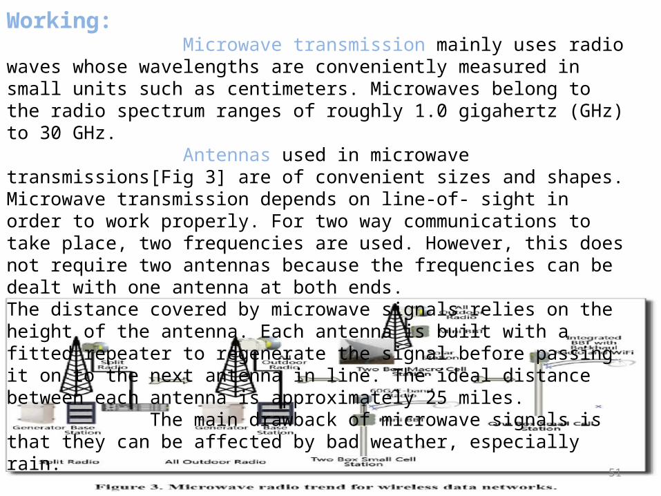
Working: Microwave transmission mainly uses radio waves whose wavelengths are conveniently measured in small units such as centimeters. Microwaves belong to the radio spectrum ranges of roughly 1.0 gigahertz (GHz) to 30 GHz. Antennas used in microwave transmissions[Fig 3] are of convenient sizes and shapes. Microwave transmission depends on line-of- sight in order to work properly. For two way communications to take place, two frequencies are used. However, this does not require two antennas because the frequencies can be dealt with one antenna at both ends.The distance covered by microwave signals relies on the height of the antenna. Each antenna is built with a fitted repeater to regenerate the signal before passing it on to the next antenna in line. The ideal distance between each antenna is approximately 25 miles. The main drawback of microwave signals is that they can be affected by bad weather, especially rain.
52
4.WIRELESS CHANNEL & IT’S EVOLUTION -
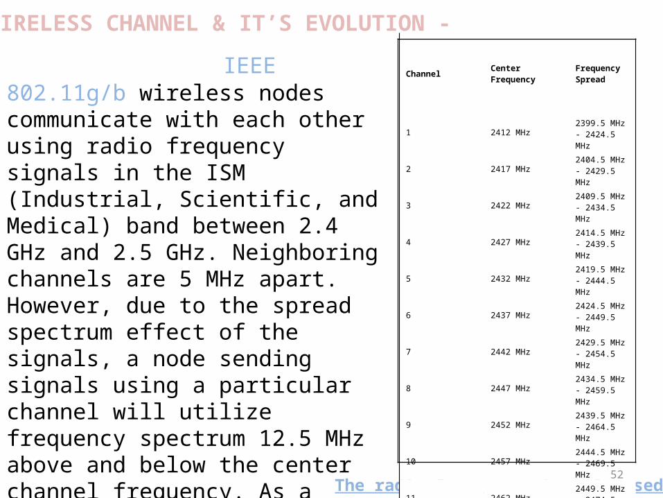
IEEE 802.11g/b wireless nodes communicate with each other using radio frequency signals in the ISM (Industrial, Scientific, and Medical) band between 2.4 GHz and 2.5 GHz. Neighboring channels are 5 MHz apart. However, due to the spread spectrum effect of the signals, a node sending signals using a particular channel will utilize frequency spectrum 12.5 MHz above and below the center channel frequency. As a result, two separate wireless networks using neighboring channels (for example, channel 1 and channel 2) in the same general vicinity will interfere with each other. Applying two channels that allow the maximum channel separation will decrease the amount of channel cross-talk and provide a noticeable performance increase over networks with minimal channel separation.
The radio frequency channels used are:
Channel Center FrequencyFrequency Spread
1 2412 MHz2399.5 MHz - 2424.5 MHz
2 2417 MHz2404.5 MHz - 2429.5 MHz
3 2422 MHz2409.5 MHz - 2434.5 MHz
4 2427 MHz2414.5 MHz - 2439.5 MHz
5 2432 MHz2419.5 MHz - 2444.5 MHz
6 2437 MHz2424.5 MHz - 2449.5 MHz
7 2442 MHz2429.5 MHz - 2454.5 MHz
8 2447 MHz2434.5 MHz - 2459.5 MHz
9 2452 MHz2439.5 MHz - 2464.5 MHz
10 2457 MHz2444.5 MHz - 2469.5 MHz
11 2462 MHz2449.5 MHz - 2474.5 MHz
12 2467 MHz2454.5 MHz - 2479.5 MHz
13 2472 MHz2459.5 MHz - 2484.5 MHz
53
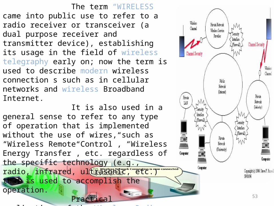
The term “WIRELESS” came into public use to refer to a radio receiver or transceiver (a dual purpose receiver and transmitter device), establishing its usage in the field of wireless telegraphy early on; now the term is used to describe modern wireless connection s such as in cellular networks and wireless Broadband Internet. It is also used in a general sense to refer to any type of operation that is implemented without the use of wires, such as “Wireless Remote Control”, “Wireless Energy Transfer”, etc. regardless of the specific technology (e.g., radio, infrared, ultrasonic, etc.) that is used to accomplish the operation. Practical applications of the Wireless Radio communication & Radio Remote Control Technology would be implemented by Nikola Tesla. In the last fifty years, Wireless Communications Industry experienced drastic changes driven by many technology innovations…

54
APPLICATION OF WIRELESS COMMUNICATION• Television Remote Control – Modern televisions use wireless remote control. Currently radio waves are also used.
• Wi-Fi – This is a wireless local area network that establishes internet connection with the portable computers.
• Security systems – For homes and office buildings, hard wired implementation security systems are replaced by the Wireless technology.
• Cellular Telephone – Radio waves are used to facilitate the operator to make phone calls from any place on the earth. CDMA, GSM, and 3G are examples of the advancement made by wireless communication in the domain.
• Wireless energy transfer – A process where a power source transmits electrical energy to electrical load which does not have built-in power source wirelessly.

55
ADVANTAGE OF WIRELESS COMMUNICATION1. Remote Area Connectivity- Workers, doctors and other professionals working in remote- location hospitals and medical centres can keep in touch with anyone through wireless communication. Non-profit organization volunteers working in remote and underserved areas can stay connected to the outside world with the help of wireless communication.
2. On-Demand Entertainment Bonanza- For those unable to keep away from their daily soap operas, reality-programs, online TV shows and Internet surfing or download activities, wireless communication ensures an entertainment bonanza on--demand and anytime.
3. Anywhere, Anytime Work- Through wireless communication, working professionals and mobile workers can work and access the Internet just about anywhere, anytime without the hassles of wires and network cables.
4. Enhanced Productivity- Workers, students, professionals and others need not be constrained by wired Internet connections or dial-up connectivity. Wireless Internet connectivity options ensures that work and assignments can be completed anywhere and enhance overall productivity of all concerned.

56
DISADVANTAGE OF WIRELESS COMMUNICATION1. Wireless communications are limited by the range of the transmitter.
2. Cost of wireless communication system and components are high.
3. When transmitting data, users must sometimes send smaller bits of data so the information moves more quickly. The size of the device that's accessing the information is also still an issue.
4. Many applications need to be reconfigured if they are going to be used through wireless connections.
5.Most client/server applications rely on a persistent connection, which is not the case with wireless.
6. Since radio waves travel through the atmosphere they can be disturbed by electrical interferences (such as lightning) that cause static.

57
WIRELESS COMMUNICATION AT TATA STEEL

58
In Tata Steel the main form of wireless communication is by the use of Walkie-talkie Sets. Tata Steel uses Motorola W/T sets. Currently GP 338/328 are used for handheld sets and GM-338/950 is used for Static Sets.However GP 300 and GM 300 are also used.
The programming and repair of all the Radio sets is done in MED,Electical(ELR Section)The amateur frequency bandwidth allotted Tata Steel is between 136 to 174 MHz.
ABOUT WIRELESS COMMUNICATION AT THE INDUSTRY
Telephone Communication at TATA STEEL Ltd. has got its separate Telecommunication Dept. This is a large setup & hence handles all the department. The department consists of both BSNL as well as its own TATA lines. The TISCO numbers are of five digits, if you want to connect to a TISCO line from your BSNL line, you have to add 21 or 61 in front of the five digit no.

59
• It is Direct communication.• Hotline• P&T• TISCO Telephony
Telephone communication at TATA STEEL has got its separate telecommunication Department. This is large set up & hence handles all the departments.
INTERCOM FACILITY
It is the communication system set up which is carried out at industrial level. This set-up is further sub divided into three categories viz.1. PA System (Public Address )2. DA system (Distributed Amplifier)3. Wireless
INDUSTRIAL COMMUNICATION
60
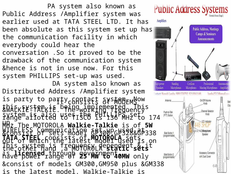
PA system also known as Public Address /Amplifier system was earlier used at TATA STEEL LTD. It has been absolute as this system set up has the communication facility in which everybody could hear the conversation .So it proved to be the drawback of the communication system &hence is not in use now. For this system PHILLIPS set-up was used. DA system also known as Distributed Address /Amplifier system is party to party contact system. Now this system is being implemented. This system is also uses the PHILLIPS set up.WIRELESS Communication set up used at TATA STEEL consists of MOTOROLA sets. This system is frequency dependent & it is licensed through government.
It consists of MODEMS &WALKIE-TALKIE. The working frequency range allotted to TISCO is 136 MHz to 174 MHz The MOTOROLA Walkie-Talkie is of 5W &consist of sets model GP300,GP328&GP338 out of which the latest model used is on the other hand ,a MOTOROLA static sets have power range of 25 MW to 40MW only &consist of models GM300,GM950 plus &GM338 is the latest model. Walkie-Talkie is implemented within industrial area where there is no network available ,no tower is there &where one has to move from place to place to carry out specific work recording the progress report in order to perform the work more efficiently & correctly.

61
MOTOROLA SETS USED IN TATA STEEL
Static Sets:-1. Motorola GM 3002. Motorola GM 9503. Motorola GM 338
Handheld Sets:-1. Motorola GP 3002. Motorola GP 3283. Motorola GP 338
62
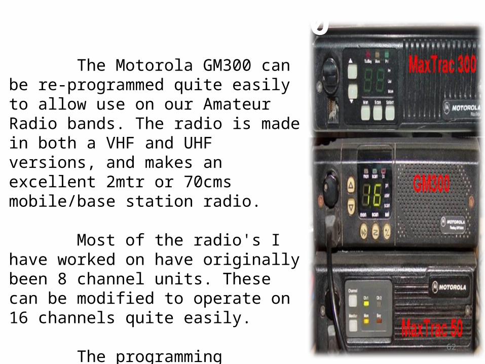
MOTOROLA GM 300 The Motorola GM300 can be re-programmed quite easily to allow use on our Amateur Radio bands. The radio is made in both a VHF and UHF versions, and makes an excellent 2mtr or 70cms mobile/base station radio.
Most of the radio's I have worked on have originally been 8 channel units. These can be modified to operate on 16 channels quite easily.
The programming interface can be made for a low cost. All it consists of is a RS232 to TTL level converter, that connects between the serial port of your PC and the radio's microphone socket.

63
Choice of Power and Versatility:The GM300 is available in multiple band with variable power levels to meet your specific needs.
Synthesized and Field Programmable:This keeps the system flexible to meet your ever changing needs and minimizes down time. The GM300 is also electronically tuned so your radio automatically adjusts for optimal performance every time you select a channel.
Unlimited Multiple-Coded Squelch Capability (PL/DPL):The GM300 offers two codes per channel (one for each transmit and receive frequency).
Wide Band Frequency Separation:Wide bandwidth allows the addition or changing of frequencies anywhere within the radio's operating band without compromising clarity or performance.
Priority Channel Scan:Both the 8 and 16-channel GM300 feature User Programmable Priority Channel Scan.
FEATURES OF GM 300 :

64
MOTOROLA GM 950 The Motorola GM950 mobile two-way radio has been developed to provide an easy to use, yet highly sophisticated, solution to your specific communication needs.The GM950 utilizes 5 tone signaling to deliver functionality which is essential to many mobile communications systems. Whether you need to improve the safety of your security personnel, or increase the efficiency of your delivery drivers, the GM950 will enable you to achieve your goal. Two GM950 models are available, allowing you to chose the configuration which best meets your requirements;
The non-display model (N2), offering basic, low-cost fixed 5 tone signaling. The display model (N3), providing "Multicall 1000" for user-variable calls, "ID Decode" (which lets the radio users know who is calling them) and "Status".

65
FEATURES OF GM 950 : Default Entry Mode:
This feature allows the radio to be configured to provide the most user-friendly operation.
Hand Held Control Mic :
Enables convenient one-hand operation of the radio functions. Emergency Operation:
Enhanced operation for your personnel in an emergency situation.- Single button press to initiate emergency operation- Hands-free transmit/receive.
Stun/Unstun:
Ability to totally disable the radio over the-air, leaving it inoperable until the 'unstun' sequence is sent.
Scan
The GM950 supports up to 2 scan lists. These scan lists are dealer programmable, however, end-users may temporarily delete unwanted channels from the list using a nuisance channel delete' function button.
66
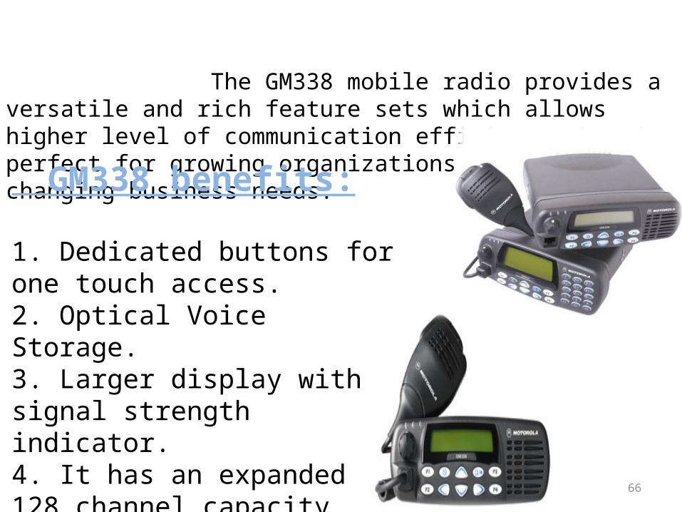
MOTOROLA GM 338 The GM338 mobile radio provides a versatile and rich feature sets which allows higher level of communication efficiency that is perfect for growing organizations with rapid changing business needs. GM338 benefits:
1. Dedicated buttons for one touch access.2. Optical Voice Storage.3. Larger display with signal strength indicator.4. It has an expanded 128 channel capacity.

67
FEATURES OF GM 338: Efficient:
14 Characters 1-line Alphanumeric Display makes it easy to read both text and icon display.
128-channel operating capacity allows individually programmed channels for enhanced communication efficiency. Voice compression and low level expansion technology ensures crisp, clear and strong audio quality. 4 customisable buttons allow one-touch easy access.
Flexible:
Two choices of signaling protocol: MDC1200 and Quick Call II.
Programmable channel spacing of 12.5/ 20/ 25 kHz offers versatility and easy migration of operating frequency band.
Versatile:
Optional voice storage board allows recording and playback of messages for up to 120 seconds.
Up to 16 pre-assigned text messages can be pre-programmed, allowing sending of frequently used messages quickly.

68
MOTOROLA GP 300 The Motorola GP300 can be re-programmed quite easily to allow use on our Amateur Radio bands. The radio is made in both a VHF and UHF versions, and makes an excellent 2mtr or 70cms portable radio. Most of the radio's I have worked on have originally been 8 channel units. These can be modified to operate on 16 channels quite easily. The programming interface can be made for a low cost. All it consists of is a RS232 to TTL level converter, that connects between the serial port of your PC and the radio.
69
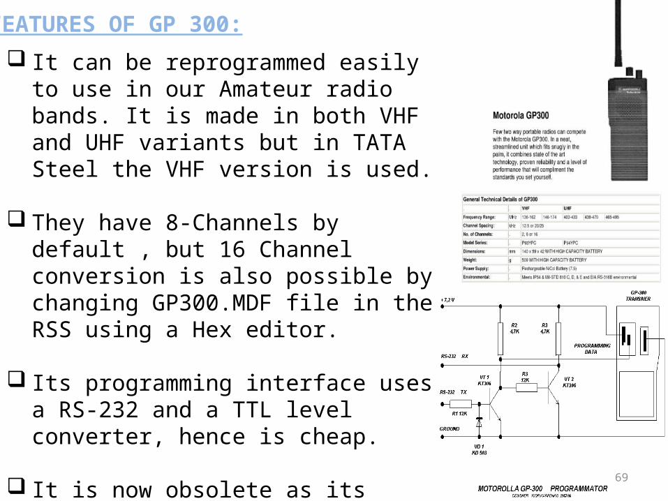
FEATURES OF GP 300:
It can be reprogrammed easily to use in our Amateur radio bands. It is made in both VHF and UHF variants but in TATA Steel the VHF version is used.
They have 8-Channels by default , but 16 Channel conversion is also possible by changing GP300.MDF file in the RSS using a Hex editor.
Its programming interface uses a RS-232 and a TTL level converter, hence is cheap.
It is now obsolete as its spare parts are not available and is being replaced slowly by GP328/338 sets.

70
MOTOROLA GP 328 The GP328 is the practical Two-Way radio solution for professionals who need to stay in contact. This practical radio increases productivity by streamlining your radio use. The GP328 is the two-way radio solution for professionals who need to stay in contact but don’t require extra features. This practical radio can easily increase productivity by keeping users communicating, yet streamlines their radio use—allowing them to concentrate on the job at hand. With the GP328, communication couldn’t be easier. Easy To Use, Lightweight Yet Rugged To Suit Your Every Need Ideal when you need:
• MDC1200 Signaling.• Maximum of 16 channels to organize work groups with ease and efficiency.• Wide range coverage within the workplace.• Simple-to-operate two-way radio.• To contact people who are mobile.• To make several calls to repeat the same message.• To manage a facility or more than one building.

71
FEATURES OF GP 328: Unsurpassed Audio Quality:
Equipped with Motorola's special voice processing technology, X-PAND™ and LLE, enables crisper, clearer and stronger audio quality, allowing you to keep communicating, even in noisy environment.
Smart Choices:Motorola’s unique MDC signaling allows the transfer of data communications at the high-speed rate of 1200 bits per second.
The Forward error correction technology enables radio to receive message,
The GP328 is certified by the US Factory Mutual standard intrinsically safe to operate in hazardous atmosphere. The built-in voice-activated feature (VOX) enables users to transmit their message in a hands-free environment, without pressing the push-to-talk button.
Easy To Use:Switchable RF Power Levels: with one button, users can switch between high and low power with reference to their specific application to conserve battery life.
Tri-colour LED Battery Gauge indicates battery status with early warning on low battery strength.
Lightweight Lithium Ion battery option makes the radio one of the lightest in its range.
72
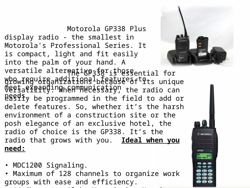
MOTOROLA GP 338 Motorola GP338 Plus display radio - the smallest in Motorola's Professional Series. It is compact, light and fit easily into the palm of your hand. A versatile alternative for those who require additional features to meet expanding communication needs. The GP338 is essential for growing organizations because of its unique versatility. When necessary, the radio can easily be programmed in the field to add or delete features. So, whether it’s the harsh environment of a construction site or the posh elegance of an exclusive hotel, the radio of choice is the GP338. It’s the radio that grows with you. Ideal when you need:
• MDC1200 Signaling.• Maximum of 128 channels to organize work groups with ease and efficiency.• 14-Character Alpha Numeric Dot-Matrix Display.• To communicate frequently with multiple work groups.• A rugged radio to perform under harsh outdoor condition.• To communicate in a high-noise environment.• To coordinate law enforcement and emergency.• Constant up-to-the-minute information.

73
FEATURES OF GP 338: Advanced Audio Technology: Motorola's special voice compression and low level expansion technology enable crisper, clearer and stronger audio quality, allowing you to keep communicating even in a noisy environment.
Versatile: Motorola's unique MDC signaling allows the transfer of data communications at the high speed rate of 1200 bits per second The Forward error correction technology enables radio to receive message, like PTT-ID display, radio status and send out remote killing signal or emergency call even though the voice signal is too weak to be heard Large display with 14 Character Alpha Numeric Dot Matrix allows immediate communication of vital information. The keypad & display illuminations provide the needed visibility to operate your radio in the dark. The built-in voice-activated feature (VOX) enables users to transmit their message in a hands-free environment, without pressing the push-to-talk button. The GP338 Plus is intrinsically safe to operate in hazardous atmosphere by the US Factory Mutual standardProving up to a maximum of 128 channels allow greater flexibility in organizing different work group.
Compact but Rugged:• Motorola's Accelerated Life Test• MIL-STD 810C, D and E

74
Radio Service Software (RSS) is software package used to program commercial Motorola two-way radios and cellular telephones. An update of RSS is CPS, a Windows-based version of the package used for some of Motorola's newer radio models. Radios are connected to PCs via proprietary programming cables. The use of genuine Motorola OEM programming cables is strongly suggested, as aftermarket brands are not as reliable and could lead to radio damage. Radio Service Software (RSS) is a software package used to program commercial Motorola two-way radios and cellular telephones. An update of RSS is CPS, a windows-based version of the package used for some of Motorola’s newer radio models. RSS-Tree
RADIO SERVICE SOFTWARE(RSS)
75
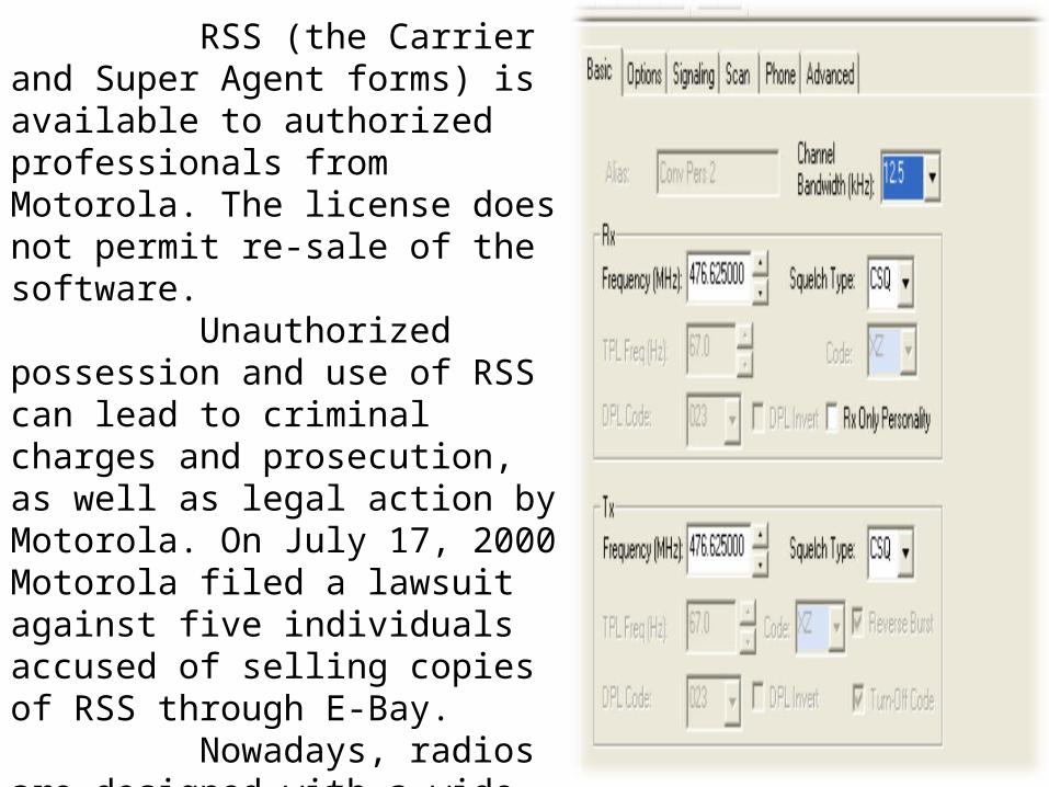
RSS (the Carrier and Super Agent forms) is available to authorized professionals from Motorola. The license does not permit re-sale of the software. Unauthorized possession and use of RSS can lead to criminal charges and prosecution, as well as legal action by Motorola. On July 17, 2000 Motorola filed a lawsuit against five individuals accused of selling copies of RSS through E-Bay. Nowadays, radios are designed with a wide range of features but still offer radio services the ability to customize and personalize radios. This happened because of modern microprocessor chip technology in the radio and the use of Radio Service Software (RSS) -a computer program that, when interfaced in the radio electronically programs and personalizes a radio with a unique set of features for each individual customer.
76
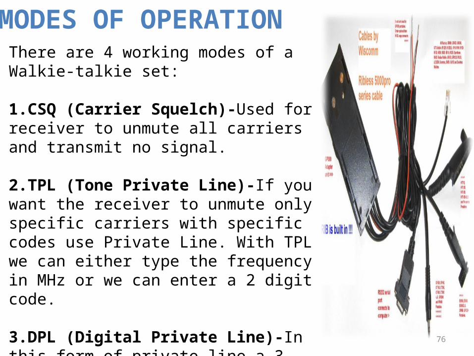
There are 4 working modes of a Walkie-talkie set:
1.CSQ (Carrier Squelch)-Used for receiver to unmute all carriers and transmit no signal.
2.TPL (Tone Private Line)-If you want the receiver to unmute only specific carriers with specific codes use Private Line. With TPL we can either type the frequency in MHz or we can enter a 2 digit code.
3.DPL (Digital Private Line)-In this form of private line a 3 digit digital sequence is entered. The carrier unmutes only if the DPL codes match.
4.INV DPL (Inverted DPL)-Inverted DPL is used only when the costumer has an audio path flipped.
MODES OF OPERATION

77
PROGRAMMING OF STATIC AND WIRELESS SETS…
78
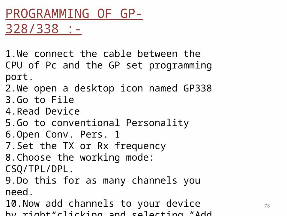
PROGRAMMING OF GP-328/338 :-
1.We connect the cable between the CPU of Pc and the GP set programming port.2.We open a desktop icon named GP3383.Go to File4.Read Device5.Go to conventional Personality6.Open Conv. Pers. 17.Set the TX or Rx frequency8.Choose the working mode: CSQ/TPL/DPL.9.Do this for as many channels you need.10.Now add channels to your device by right clicking and selecting “Add channel”11.Next Go to File>Write Device>Ok to program the device.12.The GP Device gives a loud double beep if programmed successfully.13.Now minimize tree view and exit.

79
PROGRAMMING OF GM-950 PLUS:-1.Connect the programmer unit to a power supply as well as the GM 950 plus static set to a 12V external power supply.2.We open a desktop icon named GM950 plus.3.Connect the programmer unit to the microphone jack of the static radio.4.Go to File5.Read Device6.Go to Edit.7.Select PER CHANNEL.8.Set the TX or Rx frequency9.Go to File10.Click on Write Radio.11.To add a new channel click on “edit”.12.Select Add.13.Select Add Channel.14.Press OK.15.Go to Edit.16.Open newly created channel.17.Set its Rx and TX values.119.Select Write Radio.20.The GM Device gives a loud double beep if programmed successfully.
80
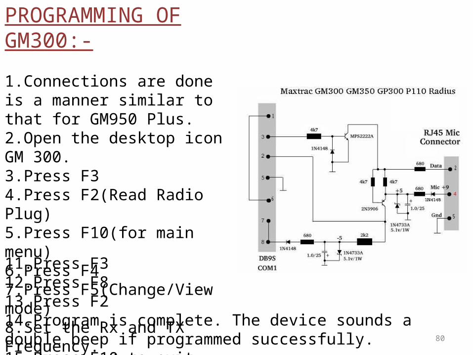
PROGRAMMING OF GM300:-
1.Connections are done is a manner similar to that for GM950 Plus.2.Open the desktop icon GM 300.3.Press F34.Press F2(Read Radio Plug)5.Press F10(for main menu)6.Press F47.Press F5(Change/View mode)8.Set the Rx and TX Frequency.9.Select the mode: TPL/DPL/CSQ.10.Press F10(for main menu)
11.Press F312.Press F813.Press F214.Program is complete. The device sounds a double beep if programmed successfully.15.Press F10 to exit.
81
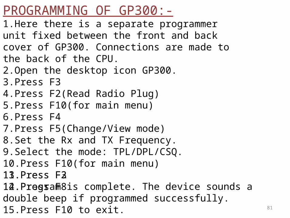
PROGRAMMING OF GP300:-1.Here there is a separate programmer unit fixed between the front and back cover of GP300. Connections are made to the back of the CPU.2.Open the desktop icon GP300.3.Press F34.Press F2(Read Radio Plug)5.Press F10(for main menu)6.Press F47.Press F5(Change/View mode)8.Set the Rx and TX Frequency.9.Select the mode: TPL/DPL/CSQ.10.Press F10(for main menu)11.Press F312.Press F813.Press F214.Program is complete. The device sounds a double beep if programmed successfully.15.Press F10 to exit.

82
MAINTENANCE AND PROBLEM DETECTION OF MOTOROLA SETS..
83
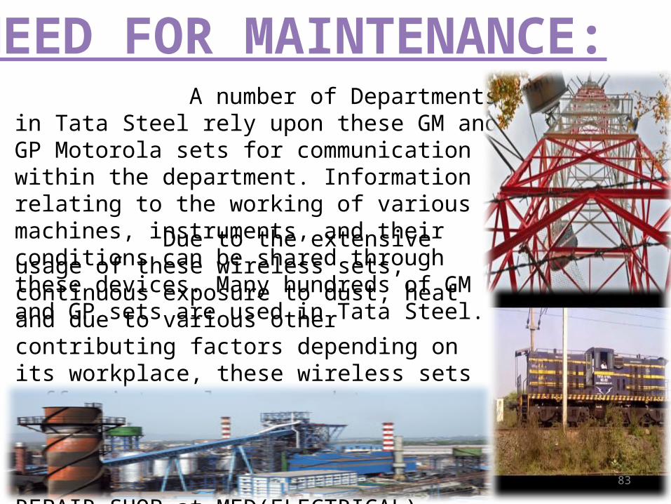
A number of Departments in Tata Steel rely upon these GM and GP Motorola sets for communication within the department. Information relating to the working of various machines, instruments, and their conditions can be shared through these devices. Many hundreds of GM and GP sets are used in Tata Steel.
Due to the extensive usage of these wireless sets, continuous exposure to dust, heat and due to various other contributing factors depending on its workplace, these wireless sets suffer internal wear and tear. Therefore, they do not function properly. In these cases, these sets are brought to ELECTRICAL REPAIR SHOP at MED(ELECTRICAL).
NEED FOR MAINTENANCE:
84
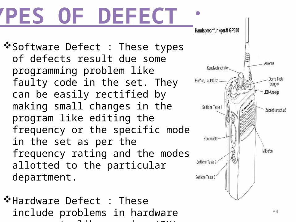
Software Defect : These types of defects result due some programming problem like faulty code in the set. They can be easily rectified by making small changes in the program like editing the frequency or the specific mode in the set as per the frequency rating and the modes allotted to the particular department.
Hardware Defect : These include problems in hardware components like receiver(RX), transmitter(TX), problems in volume knob and frequency knob, replacement of display board, burned PCB(Printed Circuit Board), speaker problem and many more problems in various hardware components.
TYPES OF DEFECT :

85
1.Software Defects are very easy to overcome as a small change in the code or program of the set is a remedy to this defect.
2.Hardware Defects are tough to overcome. As the hardware parts like receiver and transmitter are very small , extreme skill is required to repair them. Very few people are trained to do so, therefore, they replace most of the hardware faulty parts. Although, its costs them more, but it is more efficient.
3. Between April,2013 to December,2013 , 373 faulty Motorola sets have been received by the Electrical Repair Shop. Out of those 340 sets had Hardware Defects, 20 sets had Software Defects, and 13 sets were reported with both Hardware Defects and Software Defects. Most of the Hardware Defect sets received had PCB and Speaker related problems.
HANDLING SUCH PROBLEMS :

86
FAULTS/MONTHS [2013] APRIL MAY JUNE JULY AUG SEP OCT NOV DEC
Copper Wire Broken 07 07 19 09 20 03 12 11 13Insulation Damage 02 07 10 05 18 01 06 08 10
Cap Misplaced 00 02 22 09 02 00 00 00 01
Spring Bend 01 01 01 00 00 00 00 00 01
Battery 00 00 00 00 00 00 00 00 00
Battery Discharge 02 07 05 04 15 02 05 06 15
Battery Lock Broken 01 01 00 00 01 00 00 00 02
Low Power Capacity 00 00 00 01 00 00 00 00 01
Contact Problem 00 01 00 01 00 00 00 00 00
Speaker/Mic 00 00 00 00 00 00 00 00 02
Coil Open 02 00 00 000 00 00 00 00 00
Diaphram Broken 01 05 09 01 02 02 05 01 02
Underrated Supply 00 04 03 02 01 02 00 04 00
Dry Solder 00 00 03 00 00 00 02 02 03
Loose Connection 00 01 00 00 00 00 00 01 00
Manufacturing Defects 00 00 00 00 00 00 00 00 00
Due To Dust, o/p Is Low 01 00 01 00 00 00 00 00 00
WIRELESS SET FAULT STATUS MAINTAINANCE SHEET AT ELR
87
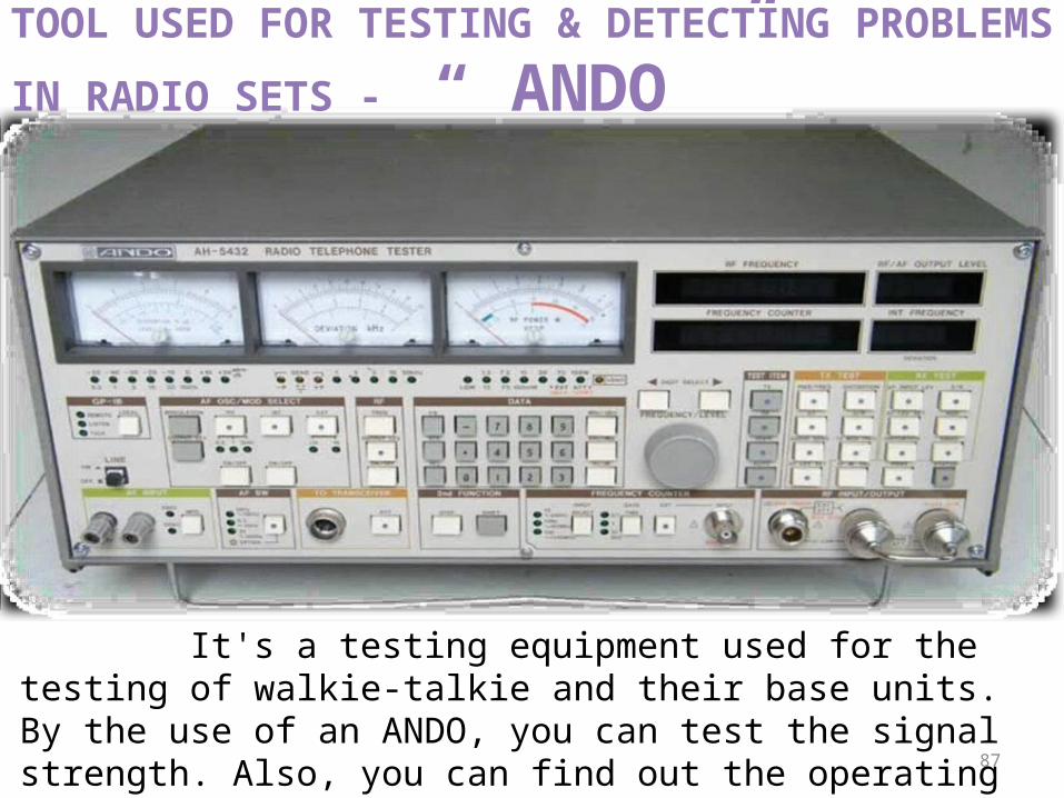
It's a testing equipment used for the testing of walkie-talkie and their base units. By the use of an ANDO, you can test the signal strength. Also, you can find out the operating frequency of the device and also the power rating of the walkie-talkie and their base units. Different Motorola set have different power wattage capacity that they transmit.
TOOL USED FOR TESTING & DETECTING PROBLEMS IN RADIO
SETS - “ ANDO ”

88
Charger & Battery
Universal Programing Cable
Linear IC Tester
Electronic MagnifierDigital IC Tester

89
The Training at TATA STEEL proved to be a fruitful job for us. It has been a great tutorial to study the diverse aspects of an Industrial Enterprise. Right from knowing the disciplines & policies, safety precautions, morals & ethics of the company to the work & management which prevails in TATA STEEL has been a great experience. Also, it was a knowledgeable approach to our entrance in the corporate world. It was really a knowledge gain achievement & experience, being in the industry. Here we came to know about the various special features & point which should be kept in the mind in order to carry on certain task right from the safety point of view to the work progress point of view.Lastly, we would like to thank all our project sub-guides along with the project head for training & guiding us for a practical approach of our respective trades. We wish more such practical experience opportunities to be provided so as to enhance our knowledge , skills & practices.
CONCLUSION
90
BIBLIOGRAPHYTo make this project a successful one, I took help from :o Our Respected project headso Sir Arun Kumar Singh o Sir Ranjeet Bhatacharjee
o Understanding Communication Systems – Don L. Cannon
o Intranet of Tata Steel
o Internet• www.motorolasolutions.com• www.easycomm.co.in/GP328• www.motorolasolutions.com• motorola.dmz.ro/Motorola/gp300-how-to-program-the-radio• www.repeater-builder.com/motorola/maxtrac/gm300• www.manualslib.com

91