wireless bomb disposal robot - -shamyl bin mansoor- home
TRANSCRIPT
Final Year Project Report
WIRELESS BOMB DISPOSAL ROBOT B.S. Computer Engineering, Batch 2001
Project Advisor Miss Umm-e-Laila
Lecturer SSUET
Submitted by Shamyl Bin Mansoor 2001-CE-401
Adnan Khan 2001-CE-350
Syed Irteza Hussain 2001-CE-361
Waqas Hashmi 2001-CE-383
Choudhry Yasir Azmat 2001-CE-405
DEPARTMENT OF COMPUTER ENGINEERING Sir Syed University of Engineering and Technology
University Road, Karachi – 75300 January 2005

PREFACE
The word robot was first used by a Czechoslovakian dramatist, Karel Capek, in his
1921 play "Rossum's Universal Robots”. The Merriam - Webster Dictionary defines
robot as
1. A machine that looks and acts like a human being.
2. An automatic apparatus.
3. 3. Something guided by automatic controls.
Our project is represented the most by the third definition. The robot that we have
designed is guided by controls that take input from a human and perform certain
actions based on these inputs.
Our project is a Robotics project. Robotics is not a pure Computer Engineering
subject it is a combination of different engineering fields namely
• Mechanical Engineering
• Electrical Engineering
• Electronics Engineering
• Computer Engineering
These four fields combine to form the field of Mechatronics, of which Robotics is a
part. The famous science fiction writer Isaac Asimov introduced the term Robotics.
He defined it as the science of robots. Robotics is not a very new field as generally
thought of. Great research has been done in this field. The result can be seen in the
form of “Asimo”. “Asimo” is a robot developed by Honda, Japan. According to
scientists, the robots of today have the intelligence equal to that of a cockroach,
which does not seem very bright. But it is being said that in the next twenty years,
robots will have knowledge equal to that of a rat. This shows how much research is
being done in this field.

The robot that we have made is a command and control robot. This robot takes
commands from the user in the form of control signals and performs the required
action. The central idea behind this robot is to provide a line of defence to a bomb
disposal squad against the life threatening risk, faced by them in the event of an
explosion. It provides the squad a safe distance to dispose off a bomb, which he
normally has to do with his bear hands.

ACKNOWLEDGMENT
It would have been impossible to complete this project without the help from above.
Coming back down below, we would like to thank our internal for bearing with us.
After that we would like to thank Syed Hammad Ali, a friend and a colleague at Sir
Syed University of Engineering & Technology, Karachi, who was of great help during
the project. His knowledge of robotics and his skills really helped us during the times
when we were stuck and had nowhere to go for help. Another person we would like
to mention is ‘Athar Bhai’, who is a mechanic by profession, and has been of great
help in our project. He has helped us in implementing the design of the base and the
robotic arm. Finally we would also like to thank our parents who have been very
generous in their prayers and financially. As without their love and their financial
support this project would not have been possible.
Shamyl Bin Mansoor
Group Leader
WBDR Team
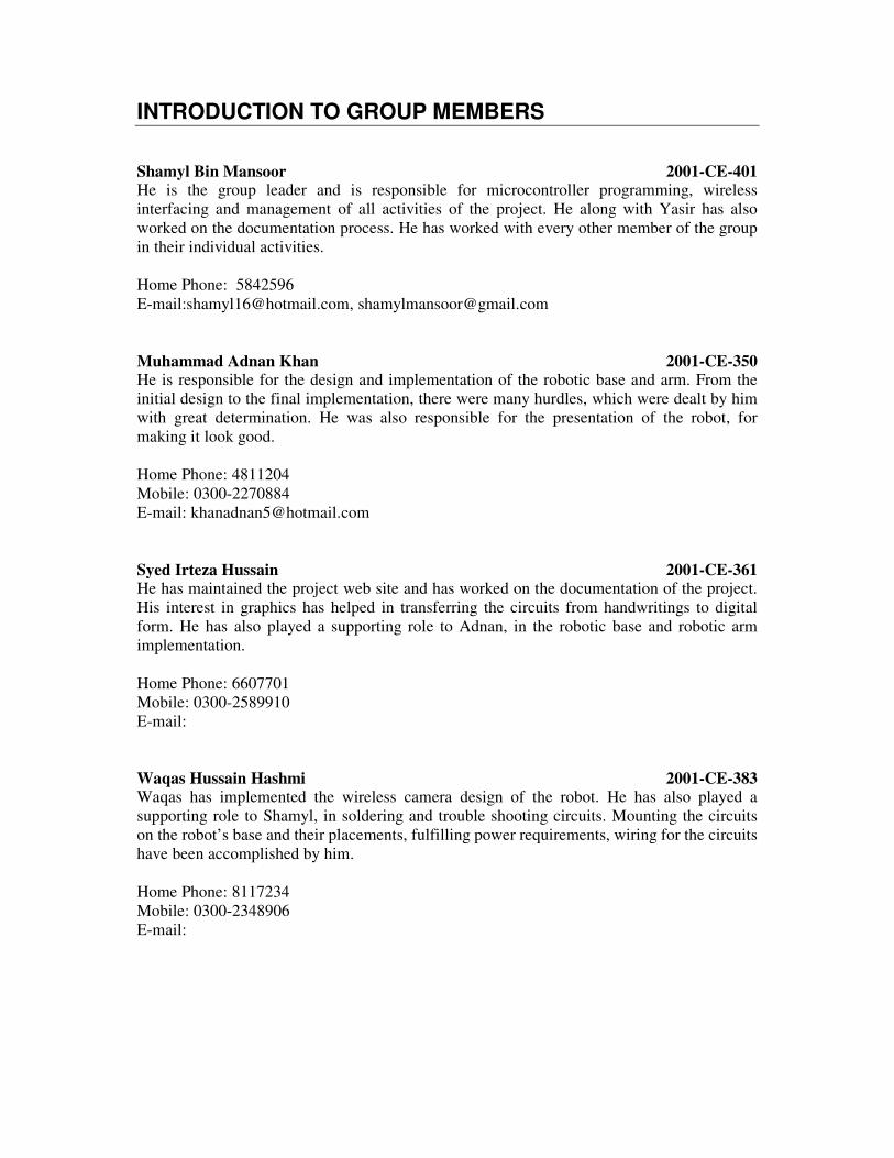
INTRODUCTION TO GROUP MEMBERS
Shamyl Bin Mansoor 2001-CE-401 He is the group leader and is responsible for microcontroller programming, wireless interfacing and management of all activities of the project. He along with Yasir has also worked on the documentation process. He has worked with every other member of the group in their individual activities. Home Phone: 5842596 E-mail:[email protected], [email protected] Muhammad Adnan Khan 2001-CE-350 He is responsible for the design and implementation of the robotic base and arm. From the initial design to the final implementation, there were many hurdles, which were dealt by him with great determination. He was also responsible for the presentation of the robot, for making it look good. Home Phone: 4811204 Mobile: 0300-2270884 E-mail: [email protected] Syed Irteza Hussain 2001-CE-361 He has maintained the project web site and has worked on the documentation of the project. His interest in graphics has helped in transferring the circuits from handwritings to digital form. He has also played a supporting role to Adnan, in the robotic base and robotic arm implementation. Home Phone: 6607701 Mobile: 0300-2589910 E-mail: Waqas Hussain Hashmi 2001-CE-383 Waqas has implemented the wireless camera design of the robot. He has also played a supporting role to Shamyl, in soldering and trouble shooting circuits. Mounting the circuits on the robot’s base and their placements, fulfilling power requirements, wiring for the circuits have been accomplished by him. Home Phone: 8117234 Mobile: 0300-2348906 E-mail:

Choudhry Yasir Azmat 2001-CE-405 He has single handedly designed the control application of the robot. He has worked in collaboration with Shamyl, in integrating the microcontroller application with the control application running on the PC. He has also been a part of the documentation process. Home Phone: 5886211 Mobile: 0303-6224989 E-mail: [email protected]
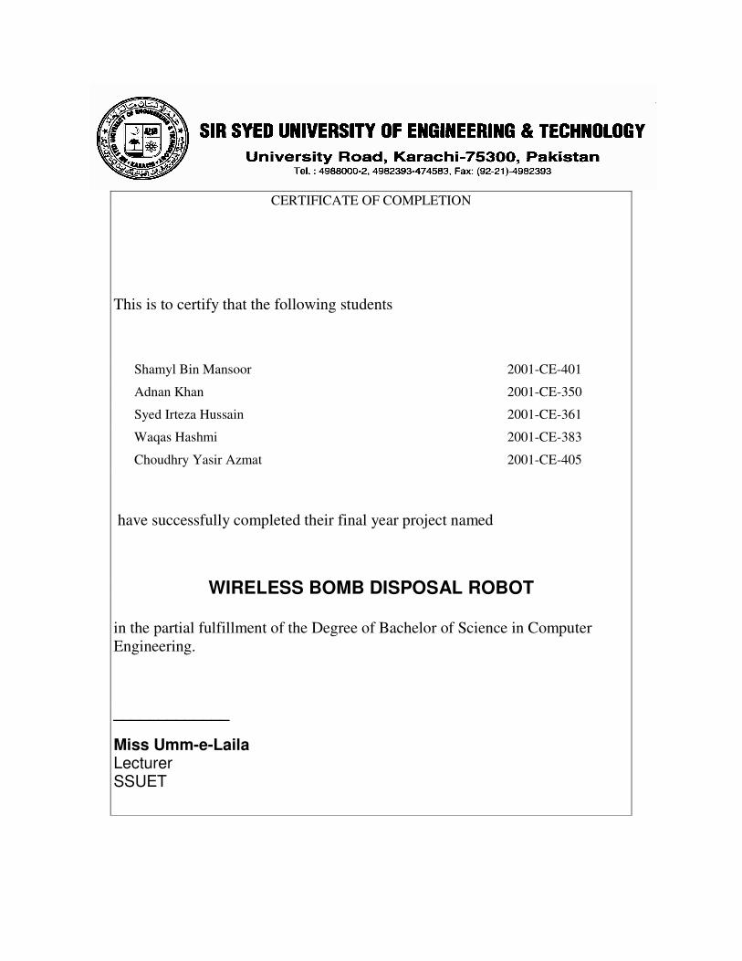
CERTIFICATE OF COMPLETION
This is to certify that the following students
Shamyl Bin Mansoor 2001-CE-401
Adnan Khan 2001-CE-350
Syed Irteza Hussain 2001-CE-361
Waqas Hashmi 2001-CE-383
Choudhry Yasir Azmat 2001-CE-405
have successfully completed their final year project named
WIRELESS BOMB DISPOSAL ROBOT
in the partial fulfillment of the Degree of Bachelor of Science in Computer Engineering.
_____________
Miss Umm-e-Laila Lecturer SSUET

CERTIFICATE OF COMPLETION
This is to certify that the following students
Shamyl Bin Mansoor 2001-CE-401
Adnan Khan 2001-CE-350
Syed Irteza Hussain 2001-CE-361
Waqas Hashmi 2001-CE-383
Choudhry Yasir Azmat 2001-CE-405
have successfully completed their final year project named
WIRELESS BOMB DISPOSAL ROBOT
in the partial fulfillment of the Degree of Bachelor of Science in Computer Engineering.
_____________
Dr. Imran Ali Tasadduq Chairman Computer Engineering Department SSUET

SYNOPSIS When we first started working on this project, we had no experience of doing a
robotics project. We had done a number of small projects of programming,
databases, graphics etc. and had taken a course on Robotics, but we had no
practical experience of any kind. Therefore to complete a project of such huge
proportions is a feat in itself, for us.
Every subsystem that we designed had its own problems. Designing the base, the
robotic arm and the gripper were easy but their implementations took a lot of effort.
The structure of the base was easy to design, but when it came to the part of
designing the steering mechanism, we faced great problems. We had to do a lot of
research, mainly on the Internet, looking for the blueprints of robots already
designed. Since our base is a vehicle chassis type base, we even went to the extent
of studying the vehicle steering mechanisms. The research also included visits to the
“Plaza” and to “Shershah”. In fact, we have become quite experts in finding the right
DC and stepper motors from “Shershah”. In the end a simple design with a powerful
DC motor was used to implement the turning mechanism.
Another major problem faced by us was the implementation of a wireless link
between the control application on a PC and the robot. Initially we tried to implement
it by converting the digital data from the PC into analog form and transmitting it using
a voice grade FM transmitter. But it wasn’t easy and quite impossible, as it turned
out later. We then used off the shelf I.Cs to implement this link.
We have used stepper motors for the elbow and the gripper of the robotic arm.
Running the stepper motor from the microcontroller was not an easy task, since
stepper motor unlike a normal DC motor requires its coils to be energized in the right
sequence for correct operation. We used a stepper motor driver IC, which required a
pulse as input. We even destroyed one of these I.Cs in the process, which cost us
Rs300.
There were countless problems during the integration of the subsystems as well but
we are happy and thankful that we have been successful in dealing with these
problems and have gained immense experience and learnt a lot from this project.

CONTENTS Chapter 1 Introduction 1
1.1 Goals and Objectives 1
1.2 System Statement of Scope 1
1.3 System Context 2
1.4 Theoretical Background 2
1.5 Technology and Tools Used in the Project 3
Chapter 2 User Interaction
2.1 User Profiles 6
2.2 Special Usage Considerations 6
Chapter 3 Functional and Data Description 7
3.1 System Architecture 7
3.1.1 Architecture Model 8
3.1.2 Subsystem Overview 11
3.2 Data Description 14
3.2.1 Major Data Objects 14
3.2.2 Relationships 15
3.3 System Interface Description 15
3.3.1 External Machine Interfaces 15
3.3.2 External System Interfaces 16
Chapter 4 Subsystem Description 17
4.1 Description of Subsystems 17
4.1.1 Subsystem Scope 17
4.1.2 Subsystem Flow Diagram 18

4.2 Description of component n 19
4.2.1 Component n Interface Description 23
4.2.2 Component n Processing Detail 25
Chapter 5 Behavioral Model and Description 30
5.1 Description for System Behavior 30
5.1.1 Events 30
5.1.2 States 32
5.2 Control Specification 35
Chapter 6 System Estimates and Actual Outcomes 36
6.1 Actual Costs 36
6.2 System Resources 38
6.2.1 System Resources Required 38
6.2.2 System Resources Used 38
Chapter 7 Test Plan 40
7.1 System Test and Procedure 40
7.2 Testing Strategy 40
7.2.1 Unit Testing 40
7.3 Integration Testing 41
7.4 Validation Testing 41
7.5 Testing Tools and Environment 43
Chapter 8 Future Enhancements 44
Chapter 9 Conclusion 46
Appendices
Appendix 1: Work Load Assignment 47
Appendix 2: Working Session of GUI 49
Appendix 3: Glossary 51
References 50
Data Sheets 52

Chapter # 1 Introduction
Sir Syed University of Engineering & Technology 13
Introduction
Goals and Objectives The main goal of the project is to provide safety to the bomb disposal squad by providing an extra line of defence.
Objectives: • Provide a remote monitoring and controlling application for analysis of a
suspicious packet (or bomb). • Allow the user to manipulate the packet using the robotic arm. • To provide visual feedback from the site of the packet. • To provide a very user-friendly control application.
System statement of scope
The Wireless Bomb Disposal Robot uses a control application, at the user end to control the robot remotely using Wireless technology. The bomb technician controls the robot using this application. Input from the user is transmitted serially over an RF link to the Robot, where it is received, identified and relayed to the appropriate module.
• The input to the system is from the user. • This input is first processed at the control application, serially transmitted
over a Radio Link. This input is then received at the robot and processed again.
• The output of the system is the processed signal to the appropriate module. This module can be a motor of the base of the robot or the robotic arm.
Major Inputs and Outputs:
• Input Signals • Video Feedback • Movement of Robotic Arm • Movement of Base
We have designed it as an assistant robot to the bomb disposal squad but there are a number of other applications of this robot. It can be used by:
• Police: In hostage situations • Military: For reconnaissance missions • Fire: To provide video feedback of the site for analysis • Nuclear: For handling hazardous or radioactive materials.

Chapter # 1 Introduction
Sir Syed University of Engineering & Technology 14
System Context
Figure 1.1: System Context Diagram
Theoretical background of the Project The project has been designed keeping in view the current law and order situation in Karachi and throughout the world. Everyday hundreds of trained personnel are either injured or lose their lives while defusing bombs. This can be reviewed by the countless number of news items appearing daily in newspapers around the world. These include the Daily DAWN of 19th JAN 2004 [1]. Another news item points to a similar story in India [2].
Although the idea of our project is original, a number of projects with similar functionalities can be found. For Example the British Police have a bomb disposal robot, the Israeli Army have it and it is also being used by bomb disposal squads and a number of states of USA.
The main idea of this robot is to provide the bomb disposal squad with safety and security from the risks that they face every day. The bomb disposal squad of Karachi has metal detectors and other equipment for bomb detection and disposal, but they have to risk their lives by approaching the bomb or the suspicious packet without any safety and precautions. Our robot provides an extra layer of protection to the bomb disposal squad by allowing them to check and analyse a suspicious packet before actually approaching it for disposal.
Mobile robots reduce or eliminate a bomb technician’s time-on-target. A robot takes risk out of potentially deadly scenarios and lets the bomb technician focus

Chapter # 1 Introduction
Sir Syed University of Engineering & Technology 15
on what to do to an explosive device rather than on the immediate danger to life and limb. Even if a robot cannot reach an item for disruption, it can still be used to relay information to aid in tool and procedure selection to moving downrange. In addition, events recorded by a robot’s camera can provide evidence for further analysis.
Technology & Tools used in the Project
• ATMEL 89C51 The Atmel 89C51 microcontroller is used for the controlling the robot. We have termed it the brain of our robot. The reason for choosing this microcontroller is its reliability and availability. Moreover it has three data ports, which are used for controlling of the different components of the robot.
• 5804B Stepper Controller
For the robotic arm we have used two uni-polar stepper motors. The 5804B is a uni-polar stepper motor controller, which generates all the necessary signals to control and run the stepper motor. It also has an enable pin for turning on/off the motor and a direction pin for changing the direction. Using the IC saves the number of port pins of the microcontroller, which can be used for other purposes. It also provides the appropriate current (maximum 1.2A), which is required to generate the appropriate torque by the motor.
• Relays for DC Control
A 12volt DC relay is used to control the DC motor from the signals of the microcontroller. A 12volt relay instead of a 5volt relay has been used to provide isolation to the microcontroller from the DC motor, which can damage the controller by drawing large current.
• 4N25 Optocoupler
The 4n25 optocoupler provides isolation to the microcontroller for driving the relay of the DC motor. It consists of gallium arsenide infrared LED and a silicon NPN phototransistor.
• ULN2003
The ULN2003 Darlington array IC has been used for interfacing between low-level logic circuitry and high power loads, the DC Motor.
• 4088 Relay:
The 4088 relay has been used to turn on the DC motor.
• MAX232 Level converter The serial port works on voltage levels of the RS232 format, which are different from the TTL (0 and +5) voltage levels. The MAX232 level converter has been used for inter-conversion between these voltage levels.
• TXM-433-LC Wireless Transmitter

Chapter # 1 Introduction
Sir Syed University of Engineering & Technology 16
The TXM wireless transmitter has been used to transmit serial data from the control application, over a wireless link using radio frequency, to the robot. The transmitter uses Amplitude Modulation at 433MHz. The reason for choosing for an off the shelf module for wireless transmission, is to save time and cost. By using this transmitter a lot of time and energy have been saved, and reliability has increased. These modules are available online.
• RXM-433-LC Wireless Receiver
The wireless receiver has been used in conjunction with the wireless transmitter to receive serial data transmitted by the control application. The receiver is connected to the microcontroller, which receives the serial data over its serial port. It uses Amplitude Modulation at 433MHz.
Software Tools Used Application Programming • Microsoft Visual Basic 6.0
Microsoft Visual Basic 6.0 has been used for the development of the control application. It integrates the video feedback from the robot and generates the appropriate signals required for controlling the movements of the robot. It also incorporates the use of Joy Stick for controlling the Robotic Arm
Components or ActiveX controls Used in Visual Basic
• Microsoft COMM control
The standard communication control has been used for serial communication between the microcontroller and the application.
• VB Skinner Pro2 Control
This control has been used to provide features of the GUI of the control application
• VideoCap Live ActiveX Control
The video feedback from the microcontroller is integrated into the application using this control.
• JK Joystick 2 Control
The robotic arm is controlled using a USB Joystick. The integration of the joystick with the application is done using the joystick control.
Microcontroller Programming
• ASM51 Assembler:
The ASM51 assembler has been used to generate hexadecimal code from assembly code, to be electrically programmed on the microcontroller. All the programming of the Atmel 89C51 microcontroller has been done using assembly language.
• EZDownloader4

Chapter # 1 Introduction
Sir Syed University of Engineering & Technology 17
This software has been used in conjunction with the AT89C51 Programmer to electrically program the microcontroller.
• Assembly Language
All code for the microcontroller has been written in assembly language.
Chapter # 2 User Interaction
Sir Syed University of Engineering & Technology 18
User Interaction
User Profiles
• End User/Controller End user or controller is the person who uses the control application to control the robot. Since it is a very user-friendly application, it only requires basic knowledge of using a computer.
• Application Developer
This is the technical person who can make the desired changes to the application as required by the customer or the end user. He can perform all the tuning and tweaking of
Special usage considerations
• The controlling of the robot requires knowledge of using a computer. • A little training is required to get used to the controls of the robot. • The robot has been built for both indoor and outdoor operation, but it
requires protection from splashing water, as it can damage the circuits.

Chapter # 3 Functional and Data Description
Sir Syed University of Engineering & Technology 19
Functional and Data Description
System Architecture
Figure 3.1: System Architecture

Chapter # 3 Functional and Data Description
Sir Syed University of Engineering & Technology 20
Architecture Model
The architecture of the robot is based on a modular approach. For every function there is a separate module, which performs its individual action. The architecture of WBDR consists of the following modules:
Software Architecture: The application is divided into the following modules according to the functions that they perform:
• Video Interface Module This module is used to initialize the video card and also to control the live feedback of the video, which is transmitted from the robot to the control application. This module also contains the facility to record the video and store it in the computers.
• Joystick Interface Module This module is used for the control and actions for the robotic arm, which is controlled by the joystick and the changes occurring with the movement of joystick results in the different movements of the robotic arm.
• Serial Interface Module Serial communication is accomplished in this module using this module. This module monitors all the data sent through the serial port and all the synchronization of the microcontroller and this module does serial port.
• Application Control Module All the events occurring when using the software application are controlled through this module. This means all the application level design and inputs of the end user are translated into control signals, which are transmitted to the microcontroller. All the user interface and error control is done in this module.
Robotic Architecture The architecture of the robot has also been designed keeping the modular approach in mind. It is divided into the following modules:
Chapter # 3 Functional and Data Description
Sir Syed University of Engineering & Technology 21
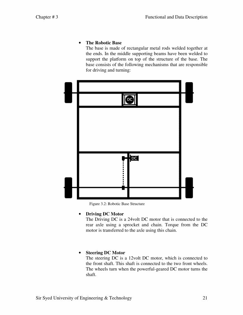
• The Robotic Base
The base is made of rectangular metal rods welded together at the ends. In the middle supporting beams have been welded to support the platform on top of the structure of the base. The base consists of the following mechanisms that are responsible for driving and turning:
Figure 3.2: Robotic Base Structure
• Driving DC Motor The Driving DC is a 24volt DC motor that is connected to the rear axle using a sprocket and chain. Torque from the DC motor is transferred to the axle using this chain.
• Steering DC Motor The steering DC is a 12volt DC motor, which is connected to the front shaft. This shaft is connected to the two front wheels. The wheels turn when the powerful-geared DC motor turns the shaft.

Chapter # 3 Functional and Data Description
Sir Syed University of Engineering & Technology 22
• The Robotic Arm
The robotic arm has been designed using metallic strips. The power to weight ratio has been kept in mind in the design of the robotic arm, as it has to be light enough to be moved by the stepper and DC motors and strong enough to be able to move nominal weight objects. It is a jointed arm type robotic arm with 3 degrees of freedom. It consists a of:
� A DC motor for the shoulder of the robotic arm. This DC
motor is mounted on a circular plate onto which two metallic strips have been mounted.
� At the next joint, the elbow, a stepper motor is fixed which is responsible for the pitch of the robotic arm. This stepper motor is responsible for the vertical movement of the arm.
� The final joint is connected to a stepper motor, which controls the movement of the gripper. The gripper is a two-finger type and can pick up objects with ease.
Figure 3.3: Structure of Robotic Arm
• The Wireless Module:
The purpose of the wireless module is to provide wireless communication between the control application and the robot. Data from the control application is transmitted from the transmitter, which is connected to the serial port of the PC, and received at the robot by the receiver. This receiver is connected to the serial port of the 89C51 microcontroller. The data transmission is done serially by the transmitter and receiver.
Chapter # 3 Functional and Data Description
Sir Syed University of Engineering & Technology 23
This transmission is based on Radio Frequency using Amplitude Modulation at 433Mhz.
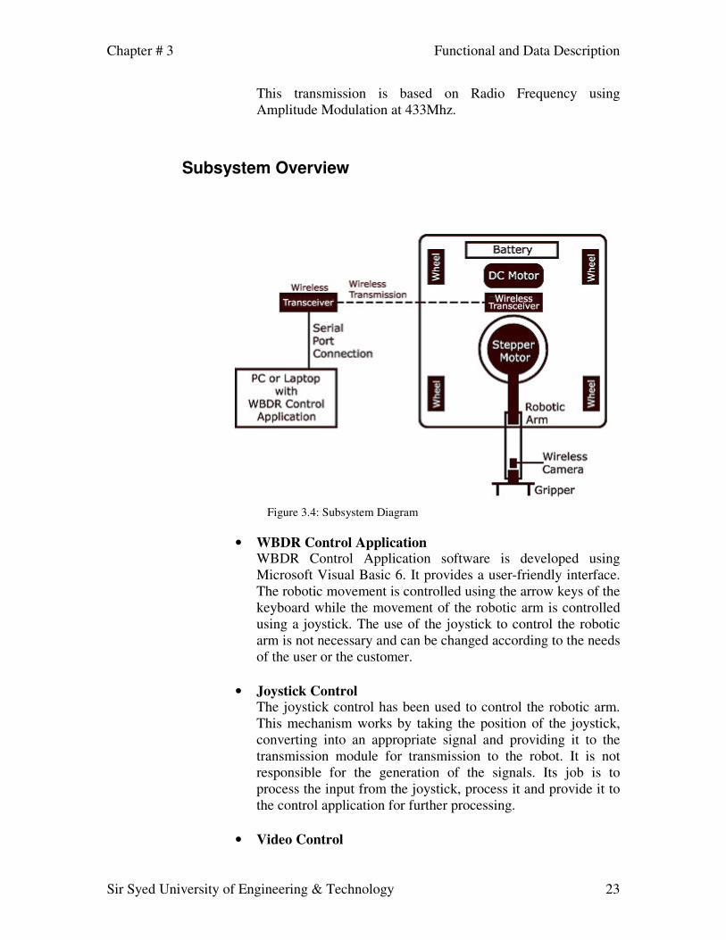
Subsystem Overview
Figure 3.4: Subsystem Diagram
• WBDR Control Application WBDR Control Application software is developed using Microsoft Visual Basic 6. It provides a user-friendly interface. The robotic movement is controlled using the arrow keys of the keyboard while the movement of the robotic arm is controlled using a joystick. The use of the joystick to control the robotic arm is not necessary and can be changed according to the needs of the user or the customer.
• Joystick Control
The joystick control has been used to control the robotic arm. This mechanism works by taking the position of the joystick, converting into an appropriate signal and providing it to the transmission module for transmission to the robot. It is not responsible for the generation of the signals. Its job is to process the input from the joystick, process it and provide it to the control application for further processing.
• Video Control

Chapter # 3 Functional and Data Description
Sir Syed University of Engineering & Technology 24
The video control turns on and off the video signal from the wireless camera. It provides features such as:
� Displaying live camera feedback � Recording the video feedback and saving it in a file for
future analysis. � Turning the video transmission on or off.
• Video Analog to Digital Conversion
The signal from the wireless camera is in analog form as the wireless camera being used is an analog camera. To be able to display this analog signal video on a computer appropriate conversion has to be done. This conversion from analog to digital signal is accomplished using a TV Tuner Card.
• Transceiver System
The transmitter being used works at a frequency of 434Mhz. Most transmitters available in the market either work at 434Mhz or 834Mhz. Some also use 900Mhz for data transmission. This transmitter gives our robot a range of about 300 feet, approximately equal to 100 feet. The receiver has the same characteristics and pairs with the transmitter to form a transceiver system.
• Wireless Camera
The wireless camera has its own transmitter and receiver system, which provides a wireless link from the robot to the control application. It is mounted on the robotic arm and provides a live view of the remote site. The application can record the video input from this camera for further analysis. Initially the camera has been mounted on the robotic arm, although it can be mounted anywhere on the robot according to the user’s need.
• Gripper
The gripper is used to manipulate the object, which poses a threat or is suspicious and can be moved from a critical place to a much safer place. It is constructed to be a two-finger type gripper. It is controlled using a stepper motor that allows a firm grip on the object.
• DC Motor DC Motors basically works by applying DC power and the shaft spins. Depending on the polarity of the electricity applied the shaft will spin in one direction or the other. We have used three DC motors. One is used for driving the robot, one for

Chapter # 3 Functional and Data Description
Sir Syed University of Engineering & Technology 25
steering left or right and third for the shoulder of the robotic arm.
• Stepper Motor A stepper motor is different from a DC motor as it provides high torque without using any gearing mechanism. Instead of continuous motion it steps through angles showing a stepping motion. It has 2 or 4 coils which provide it with high torque and also holding torque. To control the stepper motor with the microcontroller we have used a stepper motor driver IC, the UCN5804B. This IC requires the clock signal from the microcontroller and generates the appropriate signals for the stepper motor. The following circuit is used to control the stepper motor using the microcontroller.
• Power Supply The robot has its own power supply. A 12volt car battery has been used as the source voltage for the power of different modules on board the robot. The following circuit has been used for providing power to the microcontroller.
Figure 3.5: Power supply to microcontroller
The 7805 Voltage regulator IC has been used which provides 5volt output from a 12volt DC source. A capacitor is used to filter any noise at the output 5volts.
Chapter # 3 Functional and Data Description
Sir Syed University of Engineering & Technology 26
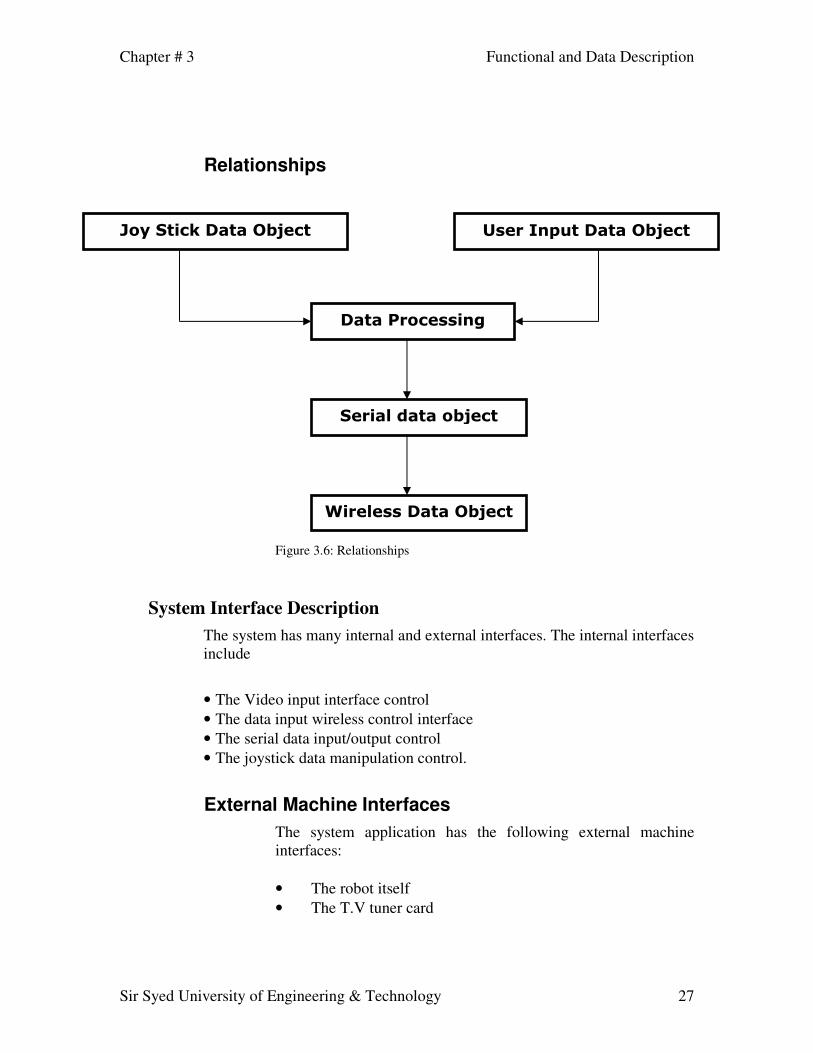
Data Description Major data objects
The major data objects in this system include the application, which generates data signals. These signals are control signals that are generated by the application depending on the input from the user.
• User Input Data
Signals are generated when the user inputs data into the application. This data is dependent on the function that has to be performed by the robot. For controlling different functions of the robot different signals are generated.
• Joy Stick Data Object
Robotic arm is controlled using the data signals generated by the joystick. This data is also transmitted serially to the robot using the wireless link.
• Serial Data Object
The data generated by the input from the user has to be transmitted serially to the microcontroller. This function is performed by the serial data object.
• Wireless Transmission Object
The data from the serial data object has to be transmitted to the robot without using any kind of wired communication. The wireless transmission object transmits data using a wireless link over radio waves.
Chapter # 3 Functional and Data Description
Sir Syed University of Engineering & Technology 27
Relationships
Figure 3.6: Relationships
System Interface Description The system has many internal and external interfaces. The internal interfaces include
• The Video input interface control • The data input wireless control interface • The serial data input/output control • The joystick data manipulation control.
External Machine Interfaces The system application has the following external machine interfaces:
• The robot itself • The T.V tuner card
������������� �����
������������� �����
���������������
�����������������
������������� �����

Chapter # 3 Functional and Data Description
Sir Syed University of Engineering & Technology 28
External System Interfaces The system is connected to the following external system interfaces:
• The wireless transmitter • The Joy Stick

Chapter # 4 Subsystem Description
Sir Syed University of Engineering & Technology 29
Subsystem Description
Figure 4.1: Detailed Subsystem Diagram
Description of Subsystems Subsystem Scope
Each subsystem has been designed using a modular approach. The subsystems can be connected and disconnected from other subsystems very easily. A modular approach on the subsystems makes it easy to trouble shoot them, consuming less time.
Chapter # 4 Subsystem Description
Sir Syed University of Engineering & Technology 30
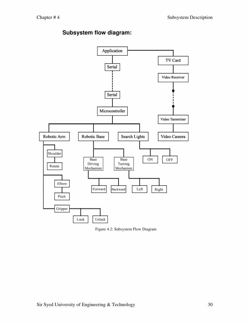
Subsystem flow diagram:
Figure 4.2: Subsystem Flow Diagram
Chapter # 4 Subsystem Description
Sir Syed University of Engineering & Technology 31
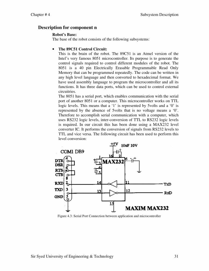
Description for component n Robot’s Base: The base of the robot consists of the following subsystems: • The 89C51 Control Circuit:
This is the brain of the robot. The 89C51 is an Atmel version of the Intel’s very famous 8051 microcontroller. Its purpose is to generate the control signals required to control different modules of the robot. The 8051 is a 40 pin Electrically Erasable Programmable Read Only Memory that can be programmed repeatedly. The code can be written in any high level language and then converted to hexadecimal format. We have used assembly language to program the microcontroller and all its functions. It has three data ports, which can be used to control external circuitries. The 8051 has a serial port, which enables communication with the serial port of another 8051 or a computer. This microcontroller works on TTL logic levels. This means that a ‘1’ is represented by 5volts and a ‘0’ is represented by the absence of 5volts that is no voltage means a ‘0’. Therefore to accomplish serial communication with a computer, which uses RS232 logic levels, inter-conversion of TTL to RS232 logic levels is required. In our circuit this has been done using a MAX232 level converter IC. It performs the conversion of signals from RS232 levels to TTL and vice versa. The following circuit has been used to perform this level conversion:
Figure 4.3: Serial Port Connection between application and microcontroller

Chapter # 4 Subsystem Description
Sir Syed University of Engineering & Technology 32
• The Stepper Motor control Circuit: We have used a stepper motor controller IC that provides the signals to the coils of the stepper motor by taking input a clock pulse from the microcontroller.
Figure 4.4: Stepper Motor Control Circuit
The following pin connections explain the signals required by this driver to run the stepper motor.
VCC: +5volts OE: Output Enable. It turns the stepper on or off. It is inverted. DR: This pin is used to change the direction of the stepper
motor. SI: This is the clock signal required to run the stepper motor continuously.

Chapter # 4 Subsystem Description
Sir Syed University of Engineering & Technology 33
• The DC Motor Control circuit: All DC motors have been controlled using the following circuit:
Figure 4.5: DC Motor Control Circuit
The 4N25 is an optocoupler, which provides isolation to the microcontroller from the high voltage circuit. ULN2008 is a Darlington pair IC that provides the amount of current that is required by the relay. The third component is a 12volt relay, which is used to turn on the DC motor. The same circuit is used for changing the direction of the DC motor.
• Wireless Transmission System
The wireless transmission has been accomplished by using off the shelf transmitters and receivers. These transmitters work at 434Mhz and have the following features:
� Operates from 2.7-5.2 VDC � Low Power Consumption � Ultra-Compact Direct Serial Interface � Supports data-rates up to 5K bps � CPCA Modulation (Carrier-Present Carrier-Absent)
The control data from the transmitter is sent to Wireless Transmitter (through serial port) then transmitted to the receiver installed on the base of the robot. The transmitter sends the control data to the 8051 microcontroller, which then controls the movements of motors.

Chapter # 4 Subsystem Description
Sir Syed University of Engineering & Technology 34
• Wireless Camera An analog wireless camera is used to transmit video to the Remote Computer System, which helps in controlling the robot remotely and in Object analysis or disposal. It is mounted on the robotic arm and moves with it. The camera has its own wireless transmission system. The conversion of the analog signal from the camera to digital is done at the receiving end that is on the computer where the control application is installed. This conversion is done using a T.V tuner card.
• Gripper or end effectors
The gripper is controlled using a stepper motor. It has four fingers, which make the shape of a claw. Two bottom fingers of the gripper remain static while two top fingers move to close the claw and rest on the bottom two fingers. The robotic arm is made up of metal segments, joined by four joints. The computer controls the robot by rotating individual stepper motors connected to each joint. Unlike ordinary motors, stepper motors move in exact increments. This allows the computer to move the arm very precisely, repeating exactly the same movement over and over again. The robotic arm's job is to move an end effectors from place to place.
• DC Motor
DC motors consist of rotor-mounted windings (armature) and stationary windings (field poles). In all DC motors, except permanent magnet motors, current must be conducted to the armature windings by passing current through carbon brushes that slide over a set of copper surfaces called a commutator, which is mounted on the rotor. The commutator bars are soldered to armature coils. The brush/commutator combination makes a sliding switch that energizes particular portions of the armature, based on the position of the rotor. This process creates north and south magnetic poles on the rotor that are attracted to or repelled by north and south poles on the stator, which are formed by passing direct current through the field windings. It's this magnetic attraction and repulsion that causes the rotor to rotate.
• Stepper Motor
Stepper motors provide open loop, relative motion control. Open loop means that, when you command the motor to take 42 steps, it provides no direct means of determining that it actually did so. The control is relative, meaning that there is no way to determine the shaft position directly. You can only command the motor to rotate a certain amount clockwise or counter-clockwise from its current position. These "commands" consist of energizing the various motor coils in a particular sequence of patterns. Each pattern causes the motor to move one step. Smooth motion results from presenting the patterns in the proper order.

Chapter # 4 Subsystem Description
Sir Syed University of Engineering & Technology 35
Features that stepper motors provide include: • Excellent rotational accuracy • Large torque • Small size • Work well over a range of speeds • Can be used for motion or position control
Stepper motors produce the highest torque at low speeds. Stepper motors also have holding torque. Holding torque allows a stepper motor to hold its position firmly when not turning. This can be useful for applications where the motor may be starting and stopping, while the force acting against the motor remains present. This eliminates the need for a mechanical brake mechanism. Steppers don't simply respond to a clock signal, they have several windings, which need to be energized in the correct sequence before the motor's shaft will rotate. Reversing the order of the sequence will cause the motor to rotate the other way. If the control signals are not sent in the correct order, the motor will not turn properly. It may simply buzz and not move, or it may actually turn, but in a rough or jerky manner.
Component n interface description Characteristics of Stepper Motor Stepper motors are not just rated by voltage. The following elements characterize a given stepper motor: Voltage Stepper motors usually have a voltage rating. Exceeding the rated voltage is sometimes necessary to obtain the desired torque from a given motor, but doing so may produce excessive heat and/or shorten the life of the motor. Resistance Resistance-per-winding is another characteristic of a stepper motor. This resistance will determine current draw of the motor, as well as affect the motor's torque curve and maximum operating speed. Degrees per step This is often the most important factor in choosing a stepper motor for a given application. This factor specifies the number of degrees the shaft will rotate for each full step. Half step operation of the motor will double the number of steps/revolution, and cut the degrees-per-step in half. For unmarked motors, it is often possible to carefully count, by hand, the number of steps per revolution of the motor. The degrees per step can be calculated by dividing 360 by the number of steps in 1 complete revolution Common

Chapter # 4 Subsystem Description
Sir Syed University of Engineering & Technology 36
degree/step numbers include: 0.72, 1.8, 3.6, 7.5, 15, and even 90. Degrees per step is often referred to as the resolution of the motor. As in the case of an unmarked motor, if a motor has only the number of steps/revolution printed on it, dividing 360 by this number will yield the degree/step value. UCN 5804B Stepper Controller The UCN5804B is a uni-polar stepper motor driver. This IC provides the required signals to drive a stepper motor. Each coil of a stepper motor is energized in a sequence to step the stepper motor. This stepper driver provides these energizing signals. It provides three modes of operation. One phase, half step and step input. We have used the step input pin to drive the stepper motor. One of the limitations of this stepper driver is its incapability to drive high current stepper motors. It allows a 1-Ampere stepper motor. The direction pin is also available which can be complemented at any moment to change the direction of the stepper motor. An output enable pin is also available to turn the stepper motor on or off. We have used this driver IC as the stepper motors used in our robotic arm are 12 volt 1 ampere stepper motors, which are compatible with this IC and also to avoid the unnecessary usage of port pins on the microcontroller. Description
Figure 4.6: Pin configuration of 5804B Stepper Controller

Chapter # 4 Subsystem Description
Sir Syed University of Engineering & Technology 37
Component n processing detail The 89C51 Control Processing
Figure 4.7: 89C51 Control Processing
89C51 Data is processed
Data Input from wireless receiver
Signal intended for
which module?
Data converted into the appropriate signal
Send Data to the module according to the signal

Chapter # 4 Subsystem Description
Sir Syed University of Engineering & Technology 38
The Stepper Motor control Processing
Figure 4.8: Stepper Motor Control Processing
Signal input to the stepper module
Movement Signal/
Direction Signal?
Perform Required Function
Chapter # 4 Subsystem Description
Sir Syed University of Engineering & Technology 39
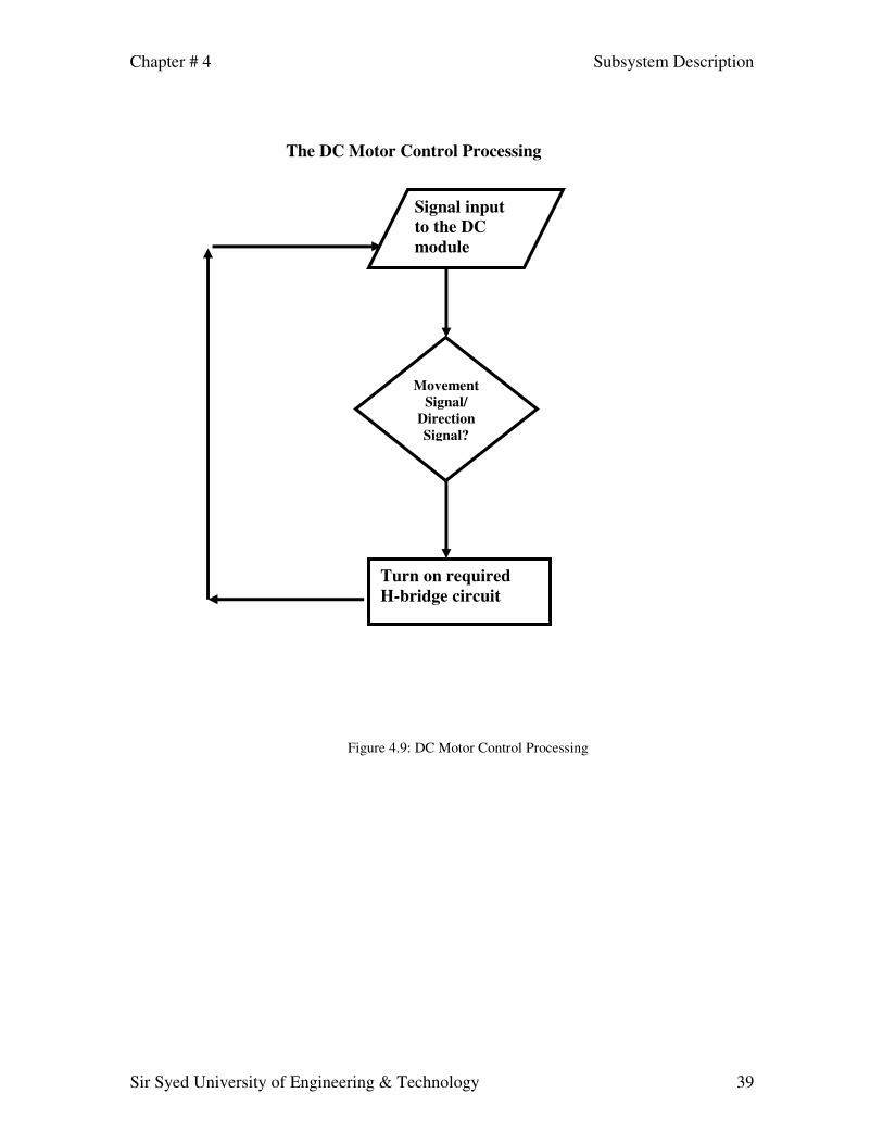
The DC Motor Control Processing
Figure 4.9: DC Motor Control Processing
Signal input to the DC module
Movement Signal/
Direction Signal?
Turn on required H-bridge circuit
Chapter # 4 Subsystem Description
Sir Syed University of Engineering & Technology 40
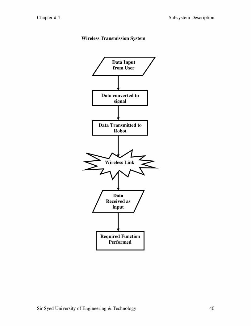
Wireless Transmission System
Data Input from User
Data converted to signal
Data Transmitted to Robot
Wireless Link
Data Received as
input
Required Function Performed
Chapter # 4 Subsystem Description
Sir Syed University of Engineering & Technology 41
Figure 4.10: Wireless Transmission System
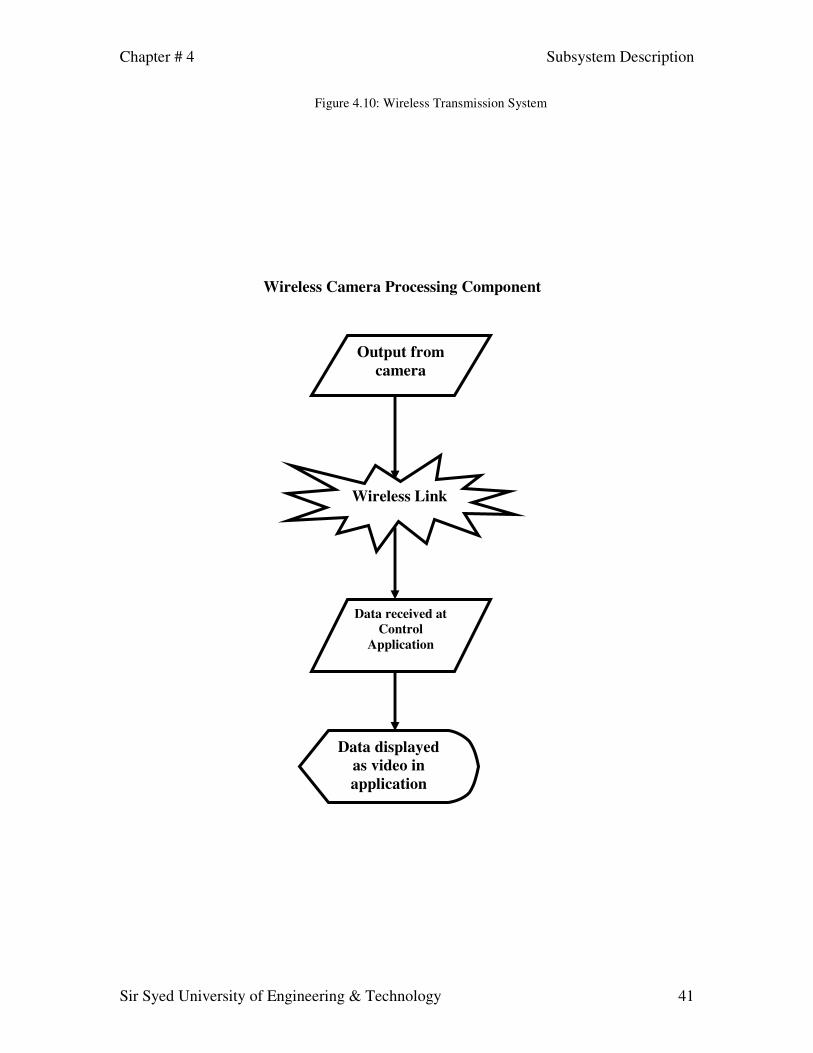
Wireless Camera Processing Component
Output from camera
Wireless Link
Data received at Control
Application
Data displayed as video in application

Chapter # 4 Subsystem Description
Sir Syed University of Engineering & Technology 42
Figure 4.8: Wireless Camera Processing
Behavioral Model and Description
Description for system behavior The robot consists of the following modules, which influence the behavior of the system (robot): • Base • Robotic Arm • Video feedback
Base consists of two DC motors, one for movement of the base and one dc motor for the steering mechanism.
Robotic arm consists of two stepper motors, which are used for the elbow and gripper movements, and one dc motor that is used for the shoulder (base) of the robotic arm.
The control application, which controls the behaviour of the base and the robotic arm, by sending control signals to the serial port using the Atmel 89C51 microcontroller, which is the brain of the robot.
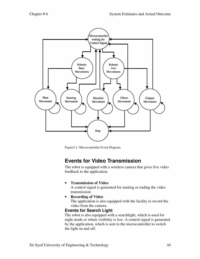
Events The event in this scenario consists of the control signals arriving at the microcontroller from the application.

Chapter # 6 System Estimates and Actual Outcome
Sir Syed University of Engineering & Technology 43
Events for Motor Movement At Microcontroller
• DC Motors
There are a total of 3 DC motors that are used in the Robot.
1. Control signal for the movement of base. 2. Control signal for the steering mechanism. 3. Control signal for the shoulder (base) of the robotic arm that
rotates the whole of the robotic arm.
• Stepper Motors There are a total of 2 Stepper motors that are used in the robotic arm.
1. Control signal for the stepper motor used for the movement and
direction of elbow of the robotic arm. 2. Control signal for the stepper motor used for the movement of
the gripper of the robotic arm.
Chapter # 6 System Estimates and Actual Outcome
Sir Syed University of Engineering & Technology 44
Figure5.1: Microcontroller Event Diagram
Events for Video Transmission The robot is equipped with a wireless camera that gives live video feedback to the application.
• Transmission of Video
A control signal is generated for starting or ending the video transmission.
• Recording of Video The application is also equipped with the facility to record the video from the camera.
Events for Search Light The robot is also equipped with a searchlight, which is used for night mode or where visibility is low. A control signal is generated by the application, which is sent to the microcontroller to switch the light on and off.

Chapter # 6 System Estimates and Actual Outcome
Sir Syed University of Engineering & Technology 45
States The states are the after effects of events generated at the microcontroller, which results in the movement of the base and robotic arm.
The states of the system depend on the events occurring at each instant; therefore each event results in a particular state. States that are generated are as fallows: ROBOTIC BASE • Movement State:
The event, which moves the DC motor of, the robotic base result s in the movement of the base which makes the whole Robot move from one place to another.
• Steering Shift State: The event, which moves the DC motor of, the robotic Steering mechanism results in the turning of the base, which turns the Robot left or right.
Figure 5.2: State Diagram of Robotic Base

Chapter # 6 System Estimates and Actual Outcome
Sir Syed University of Engineering & Technology 46
ROBOTIC ARM
• Shoulder Rotation State: The event that moves the dc motor jointed to the shoulder or base of the robotic arm results in the movement of the shoulder of the robotic arm.
• Elbow Movement State: This is the state, which is initiated when control signal for the stepper motor used for elbow of the robotic arm arrives at the microcontroller and the elbow starts to move in vertical circular motion.
• Gripper State: This is the state, which is initiated when control signal for the stepper motor used for gripper of the robotic arm arrives at the microcontroller and the gripper starts to grip or un-grip an object.
Figure 5.3: State Diagram of Robotic Arm
Chapter # 6 System Estimates and Actual Outcome
Sir Syed University of Engineering & Technology 47
VIDEO FEEDBACK
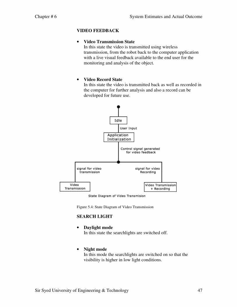
• Video Transmission State In this state the video is transmitted using wireless transmission, from the robot back to the computer application with a live visual feedback available to the end user for the monitoring and analysis of the object.
• Video Record State In this state the video is transmitted back as well as recorded in the computer for further analysis and also a record can be developed for future use.
Figure 5.4: State Diagram of Video Transmission
SEARCH LIGHT
• Daylight mode In this state the searchlights are switched off.
• Night mode
In this mode the searchlights are switched on so that the visibility is higher in low light conditions.

Chapter # 6 System Estimates and Actual Outcome
Sir Syed University of Engineering & Technology 48
Control specification Software Application The robot is controlled through the software application. The application generates control signal which are transmitted through the serial port to the microcontroller and the transmission medium is wireless.
Microcontroller The microcontroller receives the control signals and distinguishes those signals to perform the required operations. The code written on the microcontroller i.e. is assembly code makes these decisions to enable or disable the motor, which is specified by the signal. Some other controls signals, which are used to switch the searchlights on and off. For example, a scenario is briefly described below:
Scenario: When a user at the application end wants to move the robot in the forward direction and also to turn on the search lights, he or she needs to press the forward arrow key for the robot to move in the forward direction and press the space bar for the lights to be on. The Ascii code of that arrow key and space bar are sent by the application to the serial port using the wireless module.
The characters are then received at the microcontroller, which is known as the robot’s brain. The microcontroller identifies the character and on the basis of the character sent, enables the specified device (motor or light or turning mechanism).
• FK is for forward key ASCII code for the robot to move forward.
• ASCII code of ‘O’ for the lights to turn on.
Application Serial Wireless Microcontroller
Base moves in Forward Direction
Lights turn on

Chapter # 6 System Estimates and Actual Outcome
Sir Syed University of Engineering & Technology 49
System Estimates and Actual Outcome
Actual Costs
Cost of base: The base of the robot costs between Rs5000 to Rs8000. This includes the metal, welding, the nuts and bolts, motors, wiring, tires etc. The reason for such high cost was the amount of experimentation that we did, due to our lack of experience. Before the final structure of the base emerged, another one had already been abandoned due to a flaw in its design. The cost includes trips to places such as “Shershah” and “Lalukhait” for finding the right materials for the base. Cost of Robotic Arm: The robotic arm costs come to about Rs2500. These costs also include the metal rods, welding, stepper motors and other miscellaneous expenses. Cost of Circuits: A substantial amount was spent for buying I.Cs, resistors, capacitors, microcontroller, wires, vero-boards, soldering iron tips, relays etc. These costs come to about Rs3500. Such high amount was spent as a result of the testing that was required. A number of expensive I.Cs were destroyed during our experiments, which increased the costs. Cost of Wireless I.Cs: The wireless transmission has been made possible by the use of a transmitter and a receiver, which use Radio Frequency for data transfer. Since these I.Cs have been bought online from America, they have cost us about Rs12000. This includes the cost of shipping and the tax that we had to pay. Overall Costs: Table 6.1 gives the costs of the different components that were used to build this robot.

Chapter # 6 System Estimates and Actual Outcome
Sir Syed University of Engineering & Technology 50
After Mid Year Poster Presentation DATE ITEM QUANTITY PRICE TOTAL
12/17/2004 Robotic Arm Rods 1.6 Kg 65 12/17/2004 Base Metallic Sheet 4 Kg 220
7/9/2004 P805AH4 1 70 70 11/1/2004 LIDO 12 volt battery (7A) 1 500 500 11/9/2004 LIDO 12 volt battery (7A) 1 550 550 9/9/2004 Stepper Motor 4A 1 500 500
10/11/2004 UCN5804B 2 300 600 9/29/2004 Stepper Motor 2 150 300 9/21/2004 2N3055 4 20 80 9/21/2004 C828 4 4 16 8/24/2004 Steel Rod for Base 500 8/3/2004 89C51 Programmer 1 1050 1050
11/1/2004 Relay 12 V 1 15 15 11/1/2004 Relay 24 V(Testing Purposes) 1 25 25 11/1/2004 ULN 2003 12 15 180 11/1/2004 4N25 12 12 144 11/1/2004 B Connector 1 10 10 11/1/2004 Capacitor 3-18 pF 1 10 10
12/14/2004 T/B 2 Pin 8 5 40 12/14/2004 89c51 1 95 95
Table 6.1
Overall Cost of Robot: The following summary gives amount of money spent overall on this project. These are approximates: • Robotic Base: Rs.6000 • Robotic Arm: Rs.2500 • Circuits and components: Rs.3500 • Wireless I.Cs: Rs12000 • Wireless Camera Rs1800
• Overall Cost: Rs.25800 approximate.
System Resources
System Resources Required People
• End User An end user who is trained to use the application, which provides the actual controls for the robot to do its operations. The end user
Chapter # 6 System Estimates and Actual Outcome
Sir Syed University of Engineering & Technology 51
is not such a technical job so for this purpose any ordinary person with a small background of computers can be trained to do the desired operations.
In the case of a bomb disposal squad, usually the end user is the one who knows all about the bomb diffusion mechanism and has a good knowledge of the type of bombs and how to counter those bombs.
Hardware The recommended minimum hardware required for the best performance of the robot’s application is as follows:
• P-II 333 MHz Processor • 128 MB RAM • Joystick (for robotic arm controlling) (optional) • Keyboard (for Base movement) • TV Card for Video Input • Serial Port • Serial Data Transceivers
Software • Windows 98/XP Operating System • WBDR Control Application
System Resources Used People
• Application Designer An individual who has some knowledge of software engineering develops the WBDR control application that is he or she is able to develop the required parameters of the application to control the application. A programming background is needed for this job to ensure that the programmer is able to meet the requirements of the customer efficiently and quickly.
• Micro Controller Programmer The responsibility of the microcontroller programmer is to program the microcontroller. The programmer has to write the code to control external circuits from the microcontroller and

Chapter # 6 System Estimates and Actual Outcome
Sir Syed University of Engineering & Technology 52
also interface it to applications running on a computer if required.
• Hardware Designers
The hardware designers in this project have designed the whole of the hardware including the Robotic base, Robotic Arm and different mechanical works in this project.
Hardware Used The whole system was designed on a PC containing the following hardware:
• P-III 733 MHz Processor • 128 MB RAM • Joystick (for robotic arm controlling) • Keyboard (for Base movement) • TV Card for Video Input • Serial Port • Serial Data Transceivers
Robot comprises of the following hardware:
• Wireless Camera mounted on the robotic arm • Serial Data Transceivers • Atmel 89C51 Micro controller • 89C51 Micro controller programmer • Max-232 level converter IC • 5804 IC for stepper motor driving
Software • Windows 98/XP Operating System • Visual Basic 6.0 • Microsoft COMM Control • VB skinner pro 2 control • VideoCap Live ActiveX control • JK Joystick Control • EZ download Micro Controller writer software • Hyper terminal

Chapter # 7 Test Plan
Sir Syed University of Engineering & Technology 53
Test Plan
This project contains two components. The software component and the hardware component. The software component consists of the control application. The hardware component comprises of the robot. Both these two components have further internal components. All these components had to be tested individually and after being integrated as well.
System Test and Procedure The wireless bomb disposal robot consists of a number of modular components. These modules have been tested, verified individually and then integrated with other modules.
Testing strategy A modular approach has been used in designing the robot and the same approach has been taken in its testing. The following are the modules that have been tested; The Software Application The Robotic Base The DC Motor Circuit The Stepper Motor Circuit The Serial Interfacing Circuit
Unit testing
The description of each unit being tested is described below:
Software Application
Checking the control signals that are generated has tested the software application. Connecting the control application serially, to Hyper Terminal on another PC has tested these signals.
The Robotic Base
Putting different weights on it has tested the robotic base. The following table gives an idea of the testing that has been done on the base:

Chapter # 7 Test Plan
Sir Syed University of Engineering & Technology 54
Weight (Kilogram) Result (Movement)
10 100% 20 100% 30 90% 40 80% 50 75% 60 50%

Chapter # 7 Test Plan
Sir Syed University of Engineering & Technology 55
Table 7.1: Performance of Weight to Movement
The DC Motor Circuit
The DC motor has an H-Bridge circuit, which has been constructed using four relays. Each relay acts as a switch, which can be turned on or off using control signals from the microcontroller. The circuit has been tested on a breadboard by applying voltage and the control signal.
The Stepper Motor Circuit
This circuit has also been tested on a breadboard. The clock signal required by the UCN5804B stepper driver was provided by the microcontroller. An LED was first used to test the clock pulse. It’s blinking showed the clock pulse. This pulse was then applied to the Step Input of the stepper driver UCN5804B.
The Serial Interface Circuit
Serial interfacing was first tested by connecting MAX232 to the serial port of the PC and the microcontroller. Hyper Terminal was used to generate the control signals, which were tested by turning an LED on and off.
Integration Testing
After the individual testing, the robot underwent integration testing. All circuits were mounted on the robot, connected to the microcontroller circuit and tested. Control signals from the serial port of the PC were generated using the control application and tested by turning on or off the appropriate motor.
Validation testing The validation testing required the signals generated by the control application to be correct. This was verified by checking whether the
Chapter # 7 Test Plan
Sir Syed University of Engineering & Technology 56
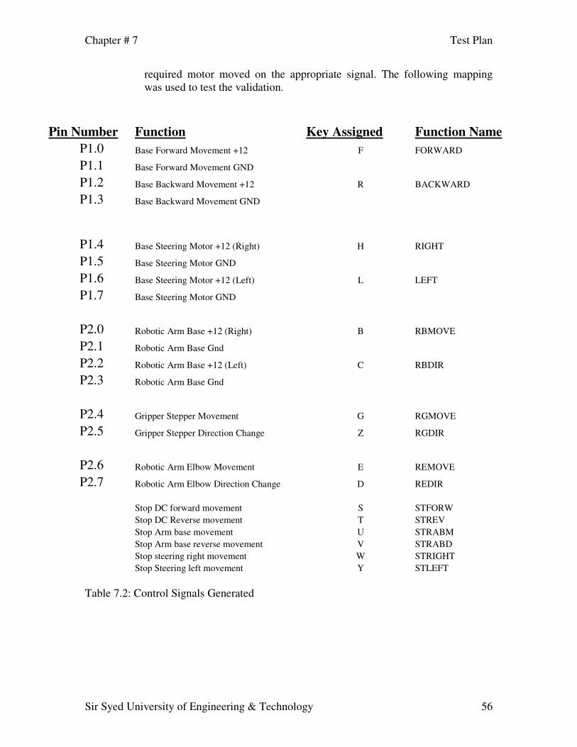
required motor moved on the appropriate signal. The following mapping was used to test the validation.
Pin Number Function Key Assigned
Function Name P1.0 Base Forward Movement +12 F FORWARD
P1.1 Base Forward Movement GND
P1.2 Base Backward Movement +12 R BACKWARD
P1.3 Base Backward Movement GND
P1.4 Base Steering Motor +12 (Right) H
RIGHT P1.5 Base Steering Motor GND
P1.6 Base Steering Motor +12 (Left) L LEFT
P1.7 Base Steering Motor GND
P2.0 Robotic Arm Base +12 (Right) B RBMOVE
P2.1 Robotic Arm Base Gnd
P2.2 Robotic Arm Base +12 (Left) C RBDIR
P2.3 Robotic Arm Base Gnd
P2.4 Gripper Stepper Movement G RGMOVE
P2.5 Gripper Stepper Direction Change Z RGDIR
P2.6 Robotic Arm Elbow Movement E REMOVE
P2.7 Robotic Arm Elbow Direction Change D REDIR Stop DC forward movement S STFORW Stop DC Reverse movement T STREV Stop Arm base movement U STRABM Stop Arm base reverse movement V STRABD Stop steering right movement W STRIGHT Stop Steering left movement Y STLEFT
Table 7.2: Control Signals Generated

Chapter # 7 Test Plan
Sir Syed University of Engineering & Technology 57
Testing tools and environment The code written for the microcontroller was tested by using a test circuit. Every time a code needed to be tested, it was programmed in the microcontroller and was tested on this circuit. The tools required for this testing are:
• A spare Atmel 89C51 microcontroller • Multimeter • Power Supply (+5volt and 12 Volt) • Atmel 89C51 programmer • An LED • Resistors • Capacitors • Serial Cable

Chapter # 8 Future Enhancements
Sir Syed University of Engineering & Technology 58
Future Enhancements
The system that we have built is a working prototype of a robot, which should be compact, fast and accurate. This prototype may not have the features and reliability of the original design. It is only being developed to ensure that the design is feasible, not impractical and can be implemented on a much larger scale in a more efficient way.
At present, the robot is not a very maneuverable machine that is it may not provide the efficiency to cope with the complex objects or it may not have the capability to maneuver into small places, which is necessary requirement. But it can be used to design such a robot, which can be small in size, fast and accurate in its movements. The gripper as compared to the ones, made by professional companies is not very efficient. But it can still perform some level of object manipulation. Hence the future enhancements may include a much smaller, faster, more reliable machine. It may have the ability to handle a much wider range of objects and the ability to maneuver them to much safer places. Some of these enhancements are described below.
• Compact Design A compact design results in a much faster motion and thus increases the accuracy and efficiency. Therefore the robot can be enhanced to be of much smaller size for the purpose of a faster and accurate operation. Compact design is also required where the situation demands the robot to reach for small places. For example, in the aftermath of an earth quake, the robot has to search for people trapped under the rubble. It has to enter holes where humans cannot enter. Hence a compact robot will easily do the job.
• Quick Movement
Being a bomb disposal robot, it requires very fast movement. This is required as the bomb disposal squad have very little time in checking out the bomb and then defusing it. Therefore a fast robot is necessary to be successfully used as a Bomb Disposal Robot.
• Improved Reliability At the moment the turning mechanism of the robot is based on the DC motor, which is not that accurate. Also the shoulder of the robotic arm or the base of the robotic arm also depends on the motion of a DC motor, which is not very feasible for the accurate motion of the robotic arm, which is necessary.
Chapter # 8 Future Enhancements
Sir Syed University of Engineering & Technology 59
The robot can be improved to be more reliable and accurate by installing stepper motors instead of the DC motors, which are more accurate and also have the feature of the holding torque, which enables the movement of heavy object with ease.
• Removable Gripper/Multi-Gripper Robotic Arm The gripper attached to the robotic arm is fixed at the moment that is, it will only work with the specific shaped of objects. Placing a gripper that can be removed and replaced by another gripper can solve this problem or a multi gripper robotic arm can be developed with more than 2 types of grippers for different type of materials and for different shaped of the objects. This will enable the robotic arm to grip and move objects, which are complex and cannot be easily moved with a single or a basic gripper.
• Artificial Intelligence At present the robot does not have the capability to make decisions on its own that is there is no built in artificial intelligence in it. Therefore the robots working is based purely on the decisions made by the end user of the robotic control application.
Therefore Artificial Intelligence may be provided to the robot for making the process of decision-making much quicker and reliable. For example a database can be merged in the application, which can be used to construct evaluation by identifying the object with the help of the camera. The camera gives input to the database that is compared with the contents of the database and if a match is found the corresponding entries of the database gives the desired actions to be performed by the robot on the object, which makes the task much easier for the end user.
Also AI may provide a threat of performing wrong operations in case of identifying the object wrong which may result in hazardous situation. Therefore if Artificial Intelligence is being implemented then it should be made sure that the accuracy rate of AI engine is almost 100% accurate otherwise it can be dangerous in such a situation.
• Night Vision Camera The robot equipped with a wireless camera, which is not very useful in situations where the visibility or light level is very low. For night mode it will be almost impossible for identifying objects because the lights, which are provided on the robot, are fixed therefore it may not be possible to view those objects which are in the dark.

Chapter # 8 Future Enhancements
Sir Syed University of Engineering & Technology 60
For night mode or places where light is low a night vision camera can be mounted on the robot instead of a standard camera, which will increase the visibility in case of no light at all.

Chapter # 9 Conclusion
Sir Syed University of Engineering & Technology 61
Conclusion
The Wireless Bomb Disposal Robot has been designed in such a way that it can cater to the needs of the bomb disposal squad, the military, the police and also for the personnel who handle radioactive materials.
It has countless applications and can be used in different environments and scenarios. For instance, at one place it can be used by the bomb disposal squad, while at another instance it can be used for handling mines. While another application can be to provide up to date information in a hostage situation.
One of the major advantages of this robot are,
• It can be altered to suit the needs of the user • It is fast and robust. • It can handle different loads. • It can be controlled remotely. • It has video feedback. • It has its own power supply. • It has a 3-degree of freedom robotic arm.

Appendices Workload Assignment
Sir Syed University of Engineering & Technology 62
Appendices Appendix1: Workload assignment After the approval of the project, different tasks were divided among the group members, mainly research and analysis. Following are the tasks assigned to the members and the work carried out by each member.
1. Wireless Transmission Assigned to Shamyl Bin Mansoor For wireless transmission two options were considered 1. Either we use a self designed wireless system 2. or use a transceiver off the shelf The second option saves time and makes the job of implementing the wireless system easier. A transceiver is available which is capable if modulating signals from the serial port and transmitting them to a range of about 250 feet.
In the first option several problems were encountered. These included • Modulating serial port signals on Radio Frequency • Transmitting these signals from the control station (PC) to the robot • Receiving these signals and interpreting them for the micro-controller • Transmitting the signals generated by the robot to the control station • Ensuring a long range bi-directional transmission
2. Microcontroller Programming For controlling the robot movements a micro-controller has been used on board the robot. Assembly language has been used for writing code for the microcontroller. An 8051 micro-controller is a good option since a typical 8051 contains:
• CPU with Boolean processor • 2 or 3 16-bit timer/counters • Programmable full-duplex serial port • 32 I/O lines (four 8-bit ports) • RAM • ROM/EPROM in some mod
3. Programming and application development Assigned to Choudhry Yasir Azmat Application development has been carried out on Microsoft Visual Basic 6.0. The following controls have been used:

Appendices Workload Assignment
Sir Syed University of Engineering & Technology 63
• MSComm control has been used for serial interfacing. • Microsoft COMM Control • VB skinner pro 2 control • VideoCap Live ActiveX control • JK Joystick Control
4. Design of the robotic arm Assigned to Adnan Khan For the Robotic Arm the following considerations have been made: • To use a Jointed Arm Design • To use a DC Motor for the shoulder (base) of the robotic arm • To use a stepper motor to for the elbow and the wrist positioning the gripper • To use a two finger gripper
5. Design of the Robot Vehicle Assigned to Irteza Hussain The base has been designed using metal rods for the structure. These rods are light in weight and hollow in between which makes them strong. DC motors have been used to drive and turn the base. The driving mechanism involves a chain and sprocket system. The steering mechanism uses the sheer force of the powerful-geared DC motor for turning in either direction. The direction of the motors have been changed using an H-bridge.
6. Interfacing the Video Camera Assigned to Waqas Hashmi An analog camera is available in the market for around Rs1100. It has been decided to use this camera. Since it is an analog camera the output from the camera is an analog signal. There are two major considerations 1. Transmitting the analog signal back to the control center (computer) 2. Converting that signal into digital format.
Following solutions to the above two problems have been used. 1. To use a Video transmitter 2. To use a T.V card for video input which is able to convert analog signal into
digital.

Appendices Working Session of GUI
Sir Syed University of Engineering & Technology 64
Appendix2: Working Session GUI
Project Web Site:
http://wbdr.cjb.net
Live Video Feedback Robotic Base Movement Status Keys
Robotic Arm Movement Status windo
Data Sent to the microcontroller is shown here

References
Sir Syed University of Engineering & Technology 65
References [1] www.dawn.com/2004/01/19/top14.htm [2] newsarchives.indiainfo.com/spotlight/gujcrisis/29defuse.html Miscellaneous Books
1. Robotics by James L. Fuller 2. The 8051 Microcontroller by Scott McKenzie
On the Web
1. www.rentron.com 2. www.iguanalabs.com/7805kit.htm 3. www.kmitl.ac.th/~kswichit/

Appendices Glossary
Sir Syed University of Engineering & Technology 66
Appendix3: Glossary Actuator The word actuator in this report means the robotic arm, which is used for the handling of the object. The robotic consists of the shoulder, elbow and the gripper.
Base Base means the main structure of the robot on which the robotic arm stands. Base is a metallic sheet on which all the components are implanted including robotic arm, batteries, control circuits, micro controller, camera and searchlights etc.
MAX232 Level Converter This is another IC, which is used to convert TTL levels voltages to RS-232 voltage levels and vice versa. This IC is used because the data transmitted to the micro controller is not in the form that is readable by the micro controller; therefore this IC first converts the RS-232 voltage level to TTL voltage, which is easily recognized by the micro controller.
Object The word object is used in the robot for the bomb or the unidentified object that is suspicious. That object or unidentified object is manipulated using the robotic Arm.
Robots Brain The micro controller placed on the Robot is known as the Robots brain, which does all the processing tasks that extracts actions to be performed by the robotic arm.
UCN5804B Stepper Driver This is an IC, which is used as a driver or controller for a stepper motor. The stepper motor is interfaced to the micro controller through this IC. Control Application The control application is the software or the application that has been designed to control the robot.