wire feeder - millerwelds · pdf filewire feeder om-211 076e june 2005 ... dual schedule...
TRANSCRIPT

Visit our website at
www.MillerWelds.com
Axcess
Processes
Description
MIG (GMAW) Welding
Wire Feeder
OM-211 076EJune 2005
File: Advanced Manufacturing Systems

Miller Electric manufactures a full lineof welders and welding related equipment.For information on other quality Millerproducts, contact your local Miller distributor to receive the latest fullline catalog or individual specification sheets. To locate your nearestdistributor or service agency call 1-800-4-A-Miller, or visit us atwww.MillerWelds.com on the web.
Thank you and congratulations on choosing Miller. Now you can getthe job done and get it done right. We know you don’t have time to doit any other way.
That’s why when Niels Miller first started building arc welders in 1929,he made sure his products offered long-lasting value and superiorquality. Like you, his customers couldn’t afford anything less. Millerproducts had to be more than the best they could be. They had to be thebest you could buy.
Today, the people that build and sell Miller products continue thetradition. They’re just as committed to providing equipment and servicethat meets the high standards of quality and value established in 1929.
This Owner’s Manual is designed to help you get the most out of yourMiller products. Please take time to read the Safety precautions. Theywill help you protect yourself against potential hazards on the worksite.
We’ve made installation and operation quickand easy. With Miller you can count on yearsof reliable service with proper maintenance.And if for some reason the unit needs repair,there’s a Troubleshooting section that willhelp you figure out what the problem is. Theparts list will then help you to decide theexact part you may need to fix the problem.Warranty and service information for yourparticular model are also provided.
Miller is the first weldingequipment manufacturer inthe U.S.A. to be registered tothe ISO 9001:2000 QualitySystem Standard.
Working as hard as you do− every power source fromMiller is backed by the mosthassle-free warranty in thebusiness.
From Miller to You
Mil_Thank 4/05

TABLE OF CONTENTS
SECTION 1 − SAFETY PRECAUTIONS - READ BEFORE USING 1 . . . . . . . . . . . . . . . . . . . . . . . . . . . . . . . . . . . 1-1. Symbol Usage 1 . . . . . . . . . . . . . . . . . . . . . . . . . . . . . . . . . . . . . . . . . . . . . . . . . . . . . . . . . . . . . . . . . . . . . . . . 1-2. Arc Welding Hazards 1 . . . . . . . . . . . . . . . . . . . . . . . . . . . . . . . . . . . . . . . . . . . . . . . . . . . . . . . . . . . . . . . . . . 1-3. Additional Symbols For Installation, Operation, And Maintenance 3 . . . . . . . . . . . . . . . . . . . . . . . . . . . . . 1-4. California Proposition 65 Warnings 3 . . . . . . . . . . . . . . . . . . . . . . . . . . . . . . . . . . . . . . . . . . . . . . . . . . . . . . .
1-5. Principal Safety Standards 4 . . . . . . . . . . . . . . . . . . . . . . . . . . . . . . . . . . . . . . . . . . . . . . . . . . . . . . . . . . . . . 1-6. EMF Information 4 . . . . . . . . . . . . . . . . . . . . . . . . . . . . . . . . . . . . . . . . . . . . . . . . . . . . . . . . . . . . . . . . . . . . . .
SECTION 2 − CONSIGNES DE SÉCURITÉ − LIRE AVANT UTILISATION 5 . . . . . . . . . . . . . . . . . . . . . . . . . . . . 2-1. Symboles utilisés 5 . . . . . . . . . . . . . . . . . . . . . . . . . . . . . . . . . . . . . . . . . . . . . . . . . . . . . . . . . . . . . . . . . . . . . 2-2. Dangers relatifs au soudage à l’arc 5 . . . . . . . . . . . . . . . . . . . . . . . . . . . . . . . . . . . . . . . . . . . . . . . . . . . . . .
2-3. Dangers supplémentaires en relation avec l’installation, le fonctionnement et la maintenance 7 . . . . . . 2-4. Proposition californienne 65 Avertissements 7 . . . . . . . . . . . . . . . . . . . . . . . . . . . . . . . . . . . . . . . . . . . . . . . 2-5. Principales normes de sécurité 8 . . . . . . . . . . . . . . . . . . . . . . . . . . . . . . . . . . . . . . . . . . . . . . . . . . . . . . . . . . 2-6. Information EMF 8 . . . . . . . . . . . . . . . . . . . . . . . . . . . . . . . . . . . . . . . . . . . . . . . . . . . . . . . . . . . . . . . . . . . . . .
SECTION 3 − INTRODUCTION 9 . . . . . . . . . . . . . . . . . . . . . . . . . . . . . . . . . . . . . . . . . . . . . . . . . . . . . . . . . . . . . . . . . 3-1. Specifications 9 . . . . . . . . . . . . . . . . . . . . . . . . . . . . . . . . . . . . . . . . . . . . . . . . . . . . . . . . . . . . . . . . . . . . . . . .
SECTION 4 − INSTALLATION 9 . . . . . . . . . . . . . . . . . . . . . . . . . . . . . . . . . . . . . . . . . . . . . . . . . . . . . . . . . . . . . . . . . . 4-1. Selecting A Location 9 . . . . . . . . . . . . . . . . . . . . . . . . . . . . . . . . . . . . . . . . . . . . . . . . . . . . . . . . . . . . . . . . . . . 4-2. Connection Diagram 10 . . . . . . . . . . . . . . . . . . . . . . . . . . . . . . . . . . . . . . . . . . . . . . . . . . . . . . . . . . . . . . . . . . .
4-3. Rear Panel Connections And Rotating Drive Assembly 11 . . . . . . . . . . . . . . . . . . . . . . . . . . . . . . . . . . . . . . 4-4. 9-Pin Network Receptacle Information 12 . . . . . . . . . . . . . . . . . . . . . . . . . . . . . . . . . . . . . . . . . . . . . . . . . . . . 4-5. Gun Recommendation Table 12 . . . . . . . . . . . . . . . . . . . . . . . . . . . . . . . . . . . . . . . . . . . . . . . . . . . . . . . . . . . . 4-6. Installing And Threading Welding Wire 13 . . . . . . . . . . . . . . . . . . . . . . . . . . . . . . . . . . . . . . . . . . . . . . . . . . . . 4-7. Feeder Display At Power Up 14 . . . . . . . . . . . . . . . . . . . . . . . . . . . . . . . . . . . . . . . . . . . . . . . . . . . . . . . . . . . .
4-8. Dual Schedule Switch Options 14 . . . . . . . . . . . . . . . . . . . . . . . . . . . . . . . . . . . . . . . . . . . . . . . . . . . . . . . . . . SECTION 5 − OPERATION 15 . . . . . . . . . . . . . . . . . . . . . . . . . . . . . . . . . . . . . . . . . . . . . . . . . . . . . . . . . . . . . . . . . . . .
5-1. Operational Terms 15 . . . . . . . . . . . . . . . . . . . . . . . . . . . . . . . . . . . . . . . . . . . . . . . . . . . . . . . . . . . . . . . . . . . . 5-2. Power Switch 16 . . . . . . . . . . . . . . . . . . . . . . . . . . . . . . . . . . . . . . . . . . . . . . . . . . . . . . . . . . . . . . . . . . . . . . . . 5-3. Front Panel Controls 17 . . . . . . . . . . . . . . . . . . . . . . . . . . . . . . . . . . . . . . . . . . . . . . . . . . . . . . . . . . . . . . . . . . .
5-4. Program Push Button 18 . . . . . . . . . . . . . . . . . . . . . . . . . . . . . . . . . . . . . . . . . . . . . . . . . . . . . . . . . . . . . . . . . . 5-5. Upper Display 18 . . . . . . . . . . . . . . . . . . . . . . . . . . . . . . . . . . . . . . . . . . . . . . . . . . . . . . . . . . . . . . . . . . . . . . . . 5-6. Lower Display 19 . . . . . . . . . . . . . . . . . . . . . . . . . . . . . . . . . . . . . . . . . . . . . . . . . . . . . . . . . . . . . . . . . . . . . . . . 5-7. Feeder Set Up Push Button 20 . . . . . . . . . . . . . . . . . . . . . . . . . . . . . . . . . . . . . . . . . . . . . . . . . . . . . . . . . . . . . 5-8. Adjust Control 20 . . . . . . . . . . . . . . . . . . . . . . . . . . . . . . . . . . . . . . . . . . . . . . . . . . . . . . . . . . . . . . . . . . . . . . . .
5-9. Process Set Up Push Button 21 . . . . . . . . . . . . . . . . . . . . . . . . . . . . . . . . . . . . . . . . . . . . . . . . . . . . . . . . . . . . 5-10. Jog/Purge 22 . . . . . . . . . . . . . . . . . . . . . . . . . . . . . . . . . . . . . . . . . . . . . . . . . . . . . . . . . . . . . . . . . . . . . . . . . . . 5-11. Reset Mode 23 . . . . . . . . . . . . . . . . . . . . . . . . . . . . . . . . . . . . . . . . . . . . . . . . . . . . . . . . . . . . . . . . . . . . . . . . . .
SECTION 6 − SETTING SEQUENCE PARAMETERS 24 . . . . . . . . . . . . . . . . . . . . . . . . . . . . . . . . . . . . . . . . . . . . . . 6-1. Sequence Parameters In A Program 24 . . . . . . . . . . . . . . . . . . . . . . . . . . . . . . . . . . . . . . . . . . . . . . . . . . . . .
SECTION 7 − MAINTENANCE 25 . . . . . . . . . . . . . . . . . . . . . . . . . . . . . . . . . . . . . . . . . . . . . . . . . . . . . . . . . . . . . . . . . 7-1. Routine Maintenance 25 . . . . . . . . . . . . . . . . . . . . . . . . . . . . . . . . . . . . . . . . . . . . . . . . . . . . . . . . . . . . . . . . . . 7-2. Diagnostics 26 . . . . . . . . . . . . . . . . . . . . . . . . . . . . . . . . . . . . . . . . . . . . . . . . . . . . . . . . . . . . . . . . . . . . . . . . . . 7-3. Troubleshooting 29 . . . . . . . . . . . . . . . . . . . . . . . . . . . . . . . . . . . . . . . . . . . . . . . . . . . . . . . . . . . . . . . . . . . . . .
SECTION 8 − ELECTRICAL DIAGRAM 30 . . . . . . . . . . . . . . . . . . . . . . . . . . . . . . . . . . . . . . . . . . . . . . . . . . . . . . . . . . SECTION 9 − PARTS LIST 32 . . . . . . . . . . . . . . . . . . . . . . . . . . . . . . . . . . . . . . . . . . . . . . . . . . . . . . . . . . . . . . . . . . . . . WARRANTY


OM-211 076 Page 1
SECTION 1 − SAFETY PRECAUTIONS - READ BEFORE USINGsom _3/05
� Warning: Protect yourself and others from injury — read and follow these precautions.
1-1. Symbol Usage
Means Warning! Watch Out! There are possible hazardswith this procedure! The possible hazards are shown inthe adjoining symbols.
� Marks a special safety message.
� Means “Note”; not safety related.
This group of symbols means Warning! Watch Out! possibleELECTRIC SHOCK, MOVING PARTS, and HOT PARTS hazards.Consult symbols and related instructions below for necessary actionsto avoid the hazards.
1-2. Arc Welding Hazards
� The symbols shown below are used throughout this manual tocall attention to and identify possible hazards. When you seethe symbol, watch out, and follow the related instructions toavoid the hazard. The safety information given below is onlya summary of the more complete safety information found inthe Safety Standards listed in Section 1-5. Read and follow allSafety Standards.
� Only qualified persons should install, operate, maintain, andrepair this unit.
� During operation, keep everybody, especially children, away.
ELECTRIC SHOCK can kill.
Touching live electrical parts can cause fatal shocksor severe burns. The electrode and work circuit iselectrically live whenever the output is on. The inputpower circuit and machine internal circuits are also
live when power is on. In semiautomatic or automatic wire welding, thewire, wire reel, drive roll housing, and all metal parts touching thewelding wire are electrically live. Incorrectly installed or improperlygrounded equipment is a hazard.
� Do not touch live electrical parts.� Wear dry, hole-free insulating gloves and body protection.� Insulate yourself from work and ground using dry insulating mats
or covers big enough to prevent any physical contact with the workor ground.
� Do not use AC output in damp areas, if movement is confined, or ifthere is a danger of falling.
� Use AC output ONLY if required for the welding process.� If AC output is required, use remote output control if present on
unit.� Additional safety precautions are required when any of the follow-
ing electrically hazardous conditions are present: in damplocations or while wearing wet clothing; on metal structures suchas floors, gratings, or scaffolds; when in cramped positions suchas sitting, kneeling, or lying; or when there is a high risk of unavoid-able or accidental contact with the workpiece or ground. For theseconditions, use the following equipment in order presented: 1) asemiautomatic DC constant voltage (wire) welder, 2) a DC manual(stick) welder, or 3) an AC welder with reduced open-circuit volt-age. In most situations, use of a DC, constant voltage wire welderis recommended. And, do not work alone!
� Disconnect input power or stop engine before installing orservicing this equipment. Lockout/tagout input power according toOSHA 29 CFR 1910.147 (see Safety Standards).
� Properly install and ground this equipment according to itsOwner’s Manual and national, state, and local codes.
� Always verify the supply ground − check and be sure that inputpower cord ground wire is properly connected to ground terminal indisconnect box or that cord plug is connected to a properlygrounded receptacle outlet.
� When making input connections, attach proper grounding conduc-tor first − double-check connections.
� Frequently inspect input power cord for damage or bare wiring −replace cord immediately if damaged − bare wiring can kill.
� Turn off all equipment when not in use.� Do not use worn, damaged, undersized, or poorly spliced cables.� Do not drape cables over your body.� If earth grounding of the workpiece is required, ground it directly
with a separate cable.� Do not touch electrode if you are in contact with the work, ground,
or another electrode from a different machine.� Do not touch electrode holders connected to two welding ma-
chines at the same time since double open-circuit voltage will bepresent.
� Use only well-maintained equipment. Repair or replace damagedparts at once. Maintain unit according to manual.
� Wear a safety harness if working above floor level.� Keep all panels and covers securely in place.� Clamp work cable with good metal-to-metal contact to workpiece
or worktable as near the weld as practical.� Insulate work clamp when not connected to workpiece to prevent
contact with any metal object.� Do not connect more than one electrode or work cable to any
single weld output terminal.
SIGNIFICANT DC VOLTAGE exists in inverter-typewelding power sources after removal of inputpower.� Turn Off inverter, disconnect input power, and discharge input
capacitors according to instructions in Maintenance Sectionbefore touching any parts.
Welding produces fumes and gases. Breathingthese fumes and gases can be hazardous to yourhealth.
FUMES AND GASES can be hazardous.
� Keep your head out of the fumes. Do not breathe the fumes.� If inside, ventilate the area and/or use local forced ventilation at the
arc to remove welding fumes and gases.� If ventilation is poor, wear an approved air-supplied respirator.� Read and understand the Material Safety Data Sheets (MSDSs)
and the manufacturer’s instructions for metals, consumables,coatings, cleaners, and degreasers.
� Work in a confined space only if it is well ventilated, or whilewearing an air-supplied respirator. Always have a trained watch-person nearby. Welding fumes and gases can displace air andlower the oxygen level causing injury or death. Be sure the breath-ing air is safe.
� Do not weld in locations near degreasing, cleaning, or spraying op-erations. The heat and rays of the arc can react with vapors to formhighly toxic and irritating gases.
� Do not weld on coated metals, such as galvanized, lead, orcadmium plated steel, unless the coating is removed from the weldarea, the area is well ventilated, and while wearing an air-suppliedrespirator. The coatings and any metals containing these elementscan give off toxic fumes if welded.
OM-211 076 Page 2
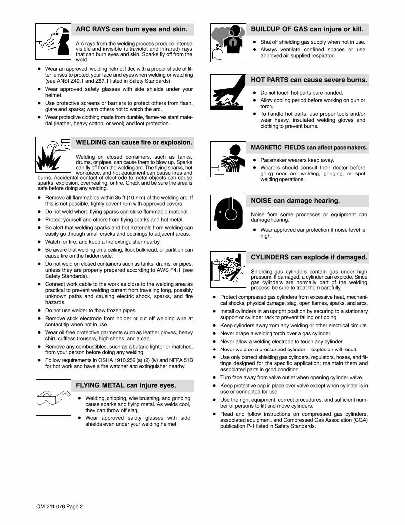
Arc rays from the welding process produce intensevisible and invisible (ultraviolet and infrared) raysthat can burn eyes and skin. Sparks fly off from theweld.
ARC RAYS can burn eyes and skin.
� Wear an approved welding helmet fitted with a proper shade of fil-ter lenses to protect your face and eyes when welding or watching(see ANSI Z49.1 and Z87.1 listed in Safety Standards).
� Wear approved safety glasses with side shields under yourhelmet.
� Use protective screens or barriers to protect others from flash,glare and sparks; warn others not to watch the arc.
� Wear protective clothing made from durable, flame-resistant mate-rial (leather, heavy cotton, or wool) and foot protection.
Welding on closed containers, such as tanks,drums, or pipes, can cause them to blow up. Sparkscan fly off from the welding arc. The flying sparks, hotworkpiece, and hot equipment can cause fires and
burns. Accidental contact of electrode to metal objects can causesparks, explosion, overheating, or fire. Check and be sure the area issafe before doing any welding.
WELDING can cause fire or explosion.
� Remove all flammables within 35 ft (10.7 m) of the welding arc. Ifthis is not possible, tightly cover them with approved covers.
� Do not weld where flying sparks can strike flammable material.
� Protect yourself and others from flying sparks and hot metal.
� Be alert that welding sparks and hot materials from welding caneasily go through small cracks and openings to adjacent areas.
� Watch for fire, and keep a fire extinguisher nearby.
� Be aware that welding on a ceiling, floor, bulkhead, or partition cancause fire on the hidden side.
� Do not weld on closed containers such as tanks, drums, or pipes,unless they are properly prepared according to AWS F4.1 (seeSafety Standards).
� Connect work cable to the work as close to the welding area aspractical to prevent welding current from traveling long, possiblyunknown paths and causing electric shock, sparks, and firehazards.
� Do not use welder to thaw frozen pipes.
� Remove stick electrode from holder or cut off welding wire atcontact tip when not in use.
� Wear oil-free protective garments such as leather gloves, heavyshirt, cuffless trousers, high shoes, and a cap.
� Remove any combustibles, such as a butane lighter or matches,from your person before doing any welding.
� Follow requirements in OSHA 1910.252 (a) (2) (iv) and NFPA 51Bfor hot work and have a fire watcher and extinguisher nearby.
FLYING METAL can injure eyes.
� Welding, chipping, wire brushing, and grindingcause sparks and flying metal. As welds cool,they can throw off slag.
� Wear approved safety glasses with sideshields even under your welding helmet.
BUILDUP OF GAS can injure or kill.
� Shut off shielding gas supply when not in use.� Always ventilate confined spaces or use
approved air-supplied respirator.
HOT PARTS can cause severe burns.
� Do not touch hot parts bare handed.� Allow cooling period before working on gun or
torch.� To handle hot parts, use proper tools and/or
wear heavy, insulated welding gloves andclothing to prevent burns.
MAGNETIC FIELDS can affect pacemakers.
� Pacemaker wearers keep away.� Wearers should consult their doctor before
going near arc welding, gouging, or spotwelding operations.
NOISE can damage hearing.
Noise from some processes or equipment candamage hearing.
� Wear approved ear protection if noise level ishigh.
Shielding gas cylinders contain gas under highpressure. If damaged, a cylinder can explode. Sincegas cylinders are normally part of the weldingprocess, be sure to treat them carefully.
CYLINDERS can explode if damaged.
� Protect compressed gas cylinders from excessive heat, mechani-cal shocks, physical damage, slag, open flames, sparks, and arcs.
� Install cylinders in an upright position by securing to a stationarysupport or cylinder rack to prevent falling or tipping.
� Keep cylinders away from any welding or other electrical circuits.
� Never drape a welding torch over a gas cylinder.
� Never allow a welding electrode to touch any cylinder.
� Never weld on a pressurized cylinder − explosion will result.
� Use only correct shielding gas cylinders, regulators, hoses, and fit-tings designed for the specific application; maintain them andassociated parts in good condition.
� Turn face away from valve outlet when opening cylinder valve.
� Keep protective cap in place over valve except when cylinder is inuse or connected for use.
� Use the right equipment, correct procedures, and sufficient num-ber of persons to lift and move cylinders.
� Read and follow instructions on compressed gas cylinders,associated equipment, and Compressed Gas Association (CGA)publication P-1 listed in Safety Standards.

OM-211 076 Page 3
1-3. Additional Symbols For Installation, Operation, And Maintenance
FIRE OR EXPLOSION hazard.
� Do not install or place unit on, over, or nearcombustible surfaces.
� Do not install unit near flammables.
� Do not overload building wiring − be sure power supply system isproperly sized, rated, and protected to handle this unit.
FALLING UNIT can cause injury.
� Use lifting eye to lift unit only, NOT runninggear, gas cylinders, or any other accessories.
� Use equipment of adequate capacity to lift andsupport unit.
� If using lift forks to move unit, be sure forks arelong enough to extend beyond opposite side ofunit.
OVERUSE can cause OVERHEATING
� Allow cooling period; follow rated duty cycle.� Reduce current or reduce duty cycle before
starting to weld again.� Do not block or filter airflow to unit.
STATIC (ESD) can damage PC boards.
� Put on grounded wrist strap BEFORE handlingboards or parts.
� Use proper static-proof bags and boxes tostore, move, or ship PC boards.
MOVING PARTS can cause injury.
� Keep away from moving parts.� Keep away from pinch points such as drive
rolls.
WELDING WIRE can cause injury.
� Do not press gun trigger until instructed to doso.
� Do not point gun toward any part of the body,other people, or any metal when threadingwelding wire.
MOVING PARTS can cause injury.
� Keep away from moving parts such as fans.� Keep all doors, panels, covers, and guards
closed and securely in place.� Have only qualified persons remove doors,
panels, covers, or guards for maintenance asnecessary.
� Reinstall doors, panels, covers, or guardswhen maintenance is finished and before re-connecting input power.
READ INSTRUCTIONS.
� Read Owner’s Manual before using or servic-ing unit.
� Use only genuine Miller/Hobart replacementparts.
H.F. RADIATION can cause interference.
� High-frequency (H.F.) can interfere with radionavigation, safety services, computers, andcommunications equipment.
� Have only qualified persons familiar withelectronic equipment perform this installation.
� The user is responsible for having a qualified electrician prompt-ly correct any interference problem resulting from the installa-tion.
� If notified by the FCC about interference, stop using theequipment at once.
� Have the installation regularly checked and maintained.
� Keep high-frequency source doors and panels tightly shut, keepspark gaps at correct setting, and use grounding and shielding tominimize the possibility of interference.
ARC WELDING can cause interference.
� Electromagnetic energy can interfere withsensitive electronic equipment such ascomputers and computer-driven equipmentsuch as robots.
� Be sure all equipment in the welding area iselectromagnetically compatible.
� To reduce possible interference, keep weld cables as short aspossible, close together, and down low, such as on the floor.
� Locate welding operation 100 meters from any sensitive elec-tronic equipment.
� Be sure this welding machine is installed and groundedaccording to this manual.
� If interference still occurs, the user must take extra measuressuch as moving the welding machine, using shielded cables,using line filters, or shielding the work area.
1-4. California Proposition 65 Warnings
� Welding or cutting equipment produces fumes or gases whichcontain chemicals known to the State of California to causebirth defects and, in some cases, cancer. (California Health &Safety Code Section 25249.5 et seq.)
� Battery posts, terminals and related accessories contain leadand lead compounds, chemicals known to the State ofCalifornia to cause cancer and birth defects or otherreproductive harm. Wash hands after handling.
For Gasoline Engines:� Engine exhaust contains chemicals known to the State of
California to cause cancer, birth defects, or other reproductiveharm.
For Diesel Engines:� Diesel engine exhaust and some of its constituents are known
to the State of California to cause cancer, birth defects, andother reproductive harm.

OM-211 076 Page 4
1-5. Principal Safety Standards
Safety in Welding, Cutting, and Allied Processes, ANSI Standard Z49.1,from Global Engineering Documents (phone: 1-877-413-5184, website:www.global.ihs.com).
Recommended Safe Practices for the Preparation for Welding and Cut-ting of Containers and Piping, American Welding Society StandardAWS F4.1 from Global Engineering Documents (phone:1-877-413-5184, website: www.global.ihs.com).
National Electrical Code, NFPA Standard 70, from National Fire Protec-tion Association, P.O. Box 9101, 1 Battery March Park, Quincy, MA02269−9101 (phone: 617−770−3000, website: www.nfpa.org).
Safe Handling of Compressed Gases in Cylinders, CGA Pamphlet P-1,from Compressed Gas Association, 1735 Jefferson Davis Highway,Suite 1004, Arlington, VA 22202−4102 (phone: 703−412−0900, web-site: www.cganet.com).
Code for Safety in Welding and Cutting, CSA Standard W117.2, fromCanadian Standards Association, Standards Sales, 178 Rexdale
Boulevard, Rexdale, Ontario, Canada M9W 1R3 (phone:800−463−6727 or in Toronto 416−747−4044, website: www.csa−in-ternational.org).
Practice For Occupational And Educational Eye And Face Protection,ANSI Standard Z87.1, from American National Standards Institute, 11West 42nd Street, New York, NY 10036−8002 (phone: 212−642−4900,website: www.ansi.org).
Standard for Fire Prevention During Welding, Cutting, and Other HotWork, NFPA Standard 51B, from National Fire Protection Association,P.O. Box 9101, 1 Battery March Park, Quincy, MA 02269−9101 (phone:617−770−3000, website: www.nfpa.org).
OSHA, Occupational Safety and Health Standards for General Indus-try, Title 29, Code of Federal Regulations (CFR), Part 1910, Subpart Q,and Part 1926, Subpart J, from U.S. Government Printing Office, Super-intendent of Documents, P.O. Box 371954, Pittsburgh, PA 15250 (thereare 10 Regional Offices−−phone for Region 5, Chicago, is312−353−2220, website: www.osha.gov).
1-6. EMF Information
Considerations About Welding And The Effects Of Low FrequencyElectric And Magnetic FieldsWelding current, as it flows through welding cables, will cause electro-magnetic fields. There has been and still is some concern about suchfields. However, after examining more than 500 studies spanning 17years of research, a special blue ribbon committee of the NationalResearch Council concluded that: “The body of evidence, in thecommittee’s judgment, has not demonstrated that exposure to power-frequency electric and magnetic fields is a human-health hazard.”However, studies are still going forth and evidence continues to beexamined. Until the final conclusions of the research are reached, youmay wish to minimize your exposure to electromagnetic fields whenwelding or cutting.To reduce magnetic fields in the workplace, use the followingprocedures:
1. Keep cables close together by twisting or taping them.
2. Arrange cables to one side and away from the operator.
3. Do not coil or drape cables around your body.
4. Keep welding power source and cables as far away from opera-tor as practical.
5. Connect work clamp to workpiece as close to the weld as possi-ble.
About Pacemakers:Pacemaker wearers consult your doctor before welding or going nearwelding operations. If cleared by your doctor, then following the aboveprocedures is recommended.
OM-211 076 Page 5
SECTION 2 − CONSIGNES DE SÉCURITÉ − LIRE AVANT UTILISATIONsom _3/05
� Avertissement : se protéger et protéger les autres contre le risque de blessure — lire et respecter ces consignes.
2-1. Symboles utilisés
Symbole graphique d’avertissement ! Attention ! Cette pro-cédure comporte des risques possibles ! Les dangers éven-tuels sont représentés par les symboles graphiques joints.
� Indique un message de sécurité particulier
� Signifie NOTE ; n’est pas relatif à la sécurité.
Ce groupe de symboles signifie Avertissement ! Attention ! Risquesd’ÉLECTROCUTION, ORGANES MOBILES et PARTIESCHAUDES. Consulter les symboles et les instructions afférentes ci-dessous concernant les mesures à prendre pour supprimerles dangers.
2-2. Dangers relatifs au soudage à l’arc
� Les symboles représentés ci-dessous sont utilisés dans ce manuelpour attirer l’attention et identifier les dangers possibles. Enprésence de l’un de ces symboles, prendre garde et suivre lesinstructions afférentes pour éviter tout risque. Les instructions enmatière de sécurité indiquées ci-dessous ne constituent qu’unsommaire des instructions de sécurité plus complètes fourniesdans les normes de sécurité énumérées dans la Section 2-5. Lire etobserver toutes les normes de sécurité.
� Seul un personnel qualifié est autorisé à installer, faire fonction-ner, entretenir et réparer cet appareil.
� Pendant le fonctionnement, maintenir à distance toutes les per-sonnes, notamment les enfants de l’appareil.
UNE DÉCHARGE ÉLECTRIQUE peutentraîner la mort.Le contact d’organes électriques sous tension peutprovoquer des accidents mortels ou des brûluresgraves. Le circuit de l’électrode et de la pièce estsous tension lorsque le courant est délivré à la
sortie. Le circuit d’alimentation et les circuits internes de la machinesont également sous tension lorsque l’alimentation est sur Marche.Dans le mode de soudage avec du fil, le fil, le dérouleur, le bloc decommande du rouleau et toutes les parties métalliques en contactavec le fil sont sous tension électrique. Un équipement installé ou misà la terre de manière incorrecte ou impropre constitue un danger.
� Ne pas toucher aux pièces électriques sous tension.� Porter des gants isolants et des vêtements de protection secs et sans
trous.� S’isoler de la pièce à couper et du sol en utilisant des housses ou des
tapis assez grands afin d’éviter tout contact physique avec la pièce àcouper ou le sol.
� Ne pas se servir de source électrique à courant électrique dans les zo-nes humides, dans les endroits confinés ou là où on risque de tomber.
� Se servir d’une source électrique à courant électrique UNIQUEMENT sile procédé de soudage le demande.
� Si l’utilisation d’une source électrique à courant électrique s’avère né-cessaire, se servir de la fonction de télécommande si l’appareil en estéquipé.
� D’autres consignes de sécurité sont nécessaires dans les conditionssuivantes : risques électriques dans un environnement humide ou si l’onporte des vêtements mouillés ; sur des structures métalliques telles quesols, grilles ou échafaudages ; en position coincée comme assise, à ge-noux ou couchée ; ou s’il y a un risque élevé de contact inévitable ouaccidentel avec la pièce à souder ou le sol. Dans ces conditions, utiliserles équipements suivants, dans l’ordre indiqué : 1) un poste à souder DCà tension constante (à fil), 2) un poste à souder DC manuel (électrode)ou 3) un poste à souder AC à tension à vide réduite. Dans la plupart dessituations, l’utilisation d’un poste à souder DC à fil à tension constanteest recommandée. En outre, ne pas travailler seul !
� Couper l’alimentation ou arrêter le moteur avant de procéderà l’installation, à la réparation ou à l’entretien de l’appareil. Déverrouillerl’alimentation selon la norme OSHA 29 CFR 1910.147 (voir normes desécurité).
� Installer le poste correctement et le mettre à la terre convenablementselon les consignes du manuel de l’opérateur et les normes nationales,provinciales et locales.
� Toujours vérifier la terre du cordon d’alimentation. Vérifier et s’assurerque le fil de terre du cordon d’alimentation est bien raccordé à la bornede terre du sectionneur ou que la fiche du cordon est raccordée à uneprise correctement mise à la terre.
� En effectuant les raccordements d’entrée, fixer d’abord le conducteurde mise à la terre approprié et contre-vérifier les connexions.
� Vérifier fréquemment le cordon d’alimentation afin de s’assurer qu’iln’est pas altéré ou à nu, le remplacer immédiatement s’il l’est. Un fil à nupeut entraîner la mort.
� L’équipement doit être hors tension lorsqu’il n’est pas utilisé.� Ne pas utiliser des câbles usés, endommagés, de grosseur insuffisante
ou mal épissés.� Ne pas enrouler les câbles autour du corps.� Si la pièce soudée doit être mise à la terre, le faire directement avec un
câble distinct.� Ne pas toucher l’électrode quand on est en contact avec la pièce, la terre
ou une électrode provenant d’une autre machine.� Ne pas toucher des porte électrodes connectés à deux machines en
même temps à cause de la présence d’une tension à vide doublée.� N’utiliser qu’un matériel en bon état. Réparer ou remplacer sur-le-
champ les pièces endommagées. Entretenir l’appareil conformément àce manuel.
� Porter un harnais de sécurité si l’on doit travailler au-dessus du sol.� S’assurer que tous les panneaux et couvercles sont correctement en
place.� Fixer le câble de retour de façon à obtenir un bon contact métal-métal
avec la pièce à souder ou la table de travail, le plus près possible de lasoudure.
� Isoler la pince de masse quand pas mis à la pièce pour éviter le contactavec tout objet métallique.
� Ne pas raccorder plus d’une électrode ou plus d’un câble de masse àune même borne de sortie de soudage.
Il reste une TENSION DC NON NÉGLIGEABLE dansles sources de soudage onduleur quand on a coupél’alimentation.� Arrêter les convertisseurs, débrancher le courant électrique et
décharger les condensateurs d’alimentation selon les instructions indi-quées dans la partie Entretien avant de toucher les pièces.
Le soudage génère des fumées et des gaz. Leurinhalation peut être dangereuse pour la santé.
LES FUMÉES ET LES GAZ peuventêtre dangereux.
� Ne pas mettre sa tête au-dessus des vapeurs. Ne pas respirer ces va-peurs.
� À l’intérieur, ventiler la zone et/ou utiliser une ventilation forcée au niveau del’arc pour l’évacuation des fumées et des gaz de soudage.
� Si la ventilation est médiocre, porter un respirateur anti-vapeurs approu-vé.
� Lire et comprendre les spécifications de sécurité des matériaux (MSDS) etles instructions du fabricant concernant les métaux, les consommables, lesrevêtements, les nettoyants et les dégraisseurs.
� Travailler dans un espace fermé seulement s’il est bien ventilé ou enportant un respirateur à alimentation d’air. Demander toujours à un sur-veillant dûment formé de se tenir à proximité. Des fumées et des gaz desoudage peuvent déplacer l’air et abaisser le niveau d’oxygène provo-quant des blessures ou des accidents mortels. S’assurer que l’air derespiration ne présente aucun danger.
� Ne pas souder dans des endroits situés à proximité d’opérations de dé-graissage, de nettoyage ou de pulvérisation. La chaleur et les rayons del’arc peuvent réagir en présence de vapeurs et former des gaz haute-ment toxiques et irritants.
� Ne pas souder des métaux munis d’un revêtement, tels que l’acier gal-vanisé, plaqué en plomb ou au cadmium à moins que le revêtement n’aitété enlevé dans la zone de soudure, que l’endroit soit bien ventilé et enportant un respirateur à alimentation d’air. Les revêtements et tous lesmétaux renfermant ces éléments peuvent dégager des fumées toxi-ques en cas de soudage.

OM-211 076 Page 6
Le rayonnement de l’arc du procédé de soudagegénère des rayons visibles et invisibles intenses(ultraviolets et infrarouges) susceptibles de provo-quer des brûlures dans les yeux et sur la peau.
Des étincelles sont projetées pendant le soudage.
LES RAYONS D’ARC peuvent entraî-ner des brûlures aux yeux et à la peau.
� Porter un casque de soudage approuvé muni de verres filtrants ap-proprié pour protéger visage et yeux pendant le soudage (voir ANSIZ49.1 et Z87.1 énuméré dans les normes de sécurité).
� Porter des lunettes de sécurité avec écrans latéraux même sous vo-tre casque.
� Avoir recours à des écrans protecteurs ou à des rideaux pourprotéger les autres contre les rayonnements les éblouissements etles étincelles ; prévenir toute personne sur les lieux de ne pasregarder l’arc.
� Porter des vêtements confectionnés avec des matières résistanteset ignifuges (cuir, coton lourd ou laine) et des bottes de protection.
Le soudage effectué sur des conteneurs fermés telsque des réservoirs, tambours ou des conduites peutprovoquer leur éclatement. Des étincelles peuventêtre projetées de l’arc de soudure. La projection
d’étincelles, des pièces chaudes et des équipements chauds peuventprovoquer des incendies et des brûlures. Le contact accidentel del’électrode avec des objets métalliques peut provoquer des étincelles,une explosion, une surchauffe ou un incendie. Avant de commencerle soudage, vérifier et s’assurer que l’endroit ne présente pas dedanger.
LE SOUDAGE peut provoquer unincendie ou une explosion.
� Déplacer toutes les substances inflammables à une distance de10,7 m de l’arc de soudage. En cas d’impossibilité, les recouvrir soi-gneusement avec des protections homologuées.
� Ne pas souder dans un endroit où des étincelles peuvent tomber surdes substances inflammables.
� Se protéger, ainsi que toute autre personne travaillant sur les lieux,contre les étincelles et le métal chaud.
� Des étincelles et des matériaux chauds du soudage peuventfacilement passer dans d’autres zones en traversant de petitesfissures et des ouvertures.
� Afin d’éliminer tout risque de feu, être vigilant et garder toujours unextincteur à la portée de main.
� Le soudage effectué sur un plafond, plancher, paroi ou séparationpeut déclencher un incendie de l’autre côté.
� Ne pas effectuer le soudage sur des conteneurs fermés tels que desréservoirs, tambours, ou conduites, à moins qu’ils n’aient été prépa-rés correctement conformément à AWS F4.1 (voir les normes desécurité).
� Brancher le câble de masse sur la pièce le plus près possible de lazone de soudage pour éviter le transport du courant sur une longuedistance par des chemins inconnus éventuels en provoquant desrisques d’électrocution, d’étincelles et d’incendie.
� Ne pas utiliser le poste de soudage pour dégeler des conduitesgelées.
� En cas de non-utilisation, enlever la baguette d’électrode du porte-électrode ou couper le fil à la pointe de contact.
� Porter des vêtements de protection exempts d’huile tels que desgants en cuir, une veste résistante, des pantalons sans revers, desbottes et un casque.
� Avant de souder, retirer toute substance combustible de ses pochestelles qu’un allumeur au butane ou des allumettes.
� Suivre les consignes de OSHA 1910.252 (a) (2) (iv) et de NFPA 51Bpour travaux de soudage et prévoir un détecteur d’incendie et un ex-tincteur à proximité.
DES PARTICULES VOLANTESpeuvent blesser les yeux.� Le soudage, l’écaillement, le passage de la
pièce à la brosse en fil de fer, et le meulagegénèrent des étincelles et des particulesmétalliques volantes. Pendant la période derefroidissement des soudures, elles risquentde projeter du laitier.
� Porter des lunettes de sécurité avec écrans latéraux ou un écranfacial.
LES ACCUMULATIONS DE GAZrisquent de provoquer des blessuresou même la mort.� Fermer l’alimentation du gaz protecteur en cas
de non-utilisation.� Veiller toujours à bien aérer les espaces confi-
nés ou se servir d’un respirateur d’adductiond’air homologué.
DES PIÈCES CHAUDES peuventprovoquer des brûlures graves.� Ne pas toucher des parties chaudes à mains
nues.� Prévoir une période de refroidissement avant
d’utiliser le pistolet ou la torche.� Ne pas toucher aux pièces chaudes, utiliser les outils recom-
mandés et porter des gants de soudage et des vêtements épaispour éviter les brûlures.
LES CHAMPS MAGNÉTIQUES peuventaffecter les stimulateurs cardiaques.� Porteurs de stimulateur cardiaque, rester
à distance.� Les porteurs d’un stimulateur cardiaque doi-
vent d’abord consulter leur médecin avant des’approcher des opérations de soudage à l’arc,de gougeage ou de soudage par points.
LE BRUIT peut endommager l’ouïe.Le bruit des processus et des équipements peutaffecter l’ouïe.
� Porter des protections approuvées pour lesoreilles si le niveau sonore est trop élevé.
Des bouteilles de gaz protecteur contiennent du gazsous haute pression. Si une bouteille est endomma-gée, elle peut exploser. Du fait que les bouteilles degaz font normalement partie du procédé de soudage, les manipuler avec précaution.
� Protéger les bouteilles de gaz comprimé d’une chaleur excessi-ve, des chocs mécaniques, des dommages physiques, du lai-tier, des flammes ouvertes, des étincelles et des arcs.
� Placer les bouteilles debout en les fixant dans un support sta-tionnaire ou dans un porte-bouteilles pour les empêcher de tom-ber ou de se renverser.
� Tenir les bouteilles éloignées des circuits de soudage ou autrescircuits électriques.
� Ne jamais placer une torche de soudage sur une bouteille à gaz.� Une électrode de soudage ne doit jamais entrer en contact avec
une bouteille.� Ne jamais souder une bouteille pressurisée − risque d’explosion.� Utiliser seulement des bouteilles de gaz protecteur, régulateurs,
tuyaux et raccords convenables pour cette application spécifi-que ; les maintenir ainsi que les éléments associés en bon état.
� Détourner votre visage du détendeur-régulateur lorsque vousouvrez la soupape de la bouteille.
� Le couvercle du détendeur doit toujours être en place, sauf lors-que la bouteille est utilisée ou qu’elle est reliée pour usage ulté-rieur.
� Utiliser les équipements corrects, les bonnes procédures et suf-fisamment de personnes pour soulever et déplacer les bouteil-les.
� Lire et suivre les instructions sur les bouteilles de gaz comprimé,l’équipement connexe et le dépliant P-1 de la CGA (CompressedGas Association) mentionné dans les principales normes de sécuri-té.
LES BOUTEILLES peuvent explosersi elles sont endommagées.
OM-211 076 Page 7
2-3. Dangers supplémentaires en relation avec l’installation, le fonctionnement et la maintenance
Risque D’INCENDIE OU D’EXPLO-SION.� Ne pas placer l’appareil sur, au-dessus ou
à proximité de surfaces inflammables.� Ne pas installer l’appareil à proximité de
produits inflammables.� Ne pas surcharger l’installation électrique − s’assurer que
l’alimentation est correctement dimensionnée et protégée avantde mettre l’appareil en service.
LA CHUTE DE L’APPAREIL peutblesser.� Utiliser l’anneau de levage uniquement pour
soulever l’appareil, NON PAS les chariots, lesbouteilles de gaz ou tout autre accessoire.
� Utiliser un équipement de levage de capacitésuffisante pour lever l’appareil.
� En utilisant des fourches de levage pour déplacer l’unité, s’assu-rer que les fourches sont suffisamment longues pour dépasserdu côté opposé de l’appareil.
L’EMPLOI EXCESSIF peut SUR-CHAUFFER L’ÉQUIPEMENT.� Prévoir une période de refroidissement ;
respecter le cycle opératoire nominal.� Réduire le courant ou le facteur de marche
avant de poursuivre le soudage.� Ne pas obstruer les passages d’air du poste.
LES CHARGES ÉLECTROSTATIQUESpeuvent endommager les circuitsimprimés.� Établir la connexion avec la barrette de terre
avant de manipuler des cartes ou des pièces.� Utiliser des pochettes et des boîtes antistati-
ques pour stocker, déplacer ou expédier descartes PC.
DES ORGANES MOBILES peuventprovoquer des blessures.� Ne pas s’approcher des organes mobiles.� Ne pas s’approcher des points de coincement
tels que des rouleaux de commande.
LES FILS DE SOUDAGE peuventprovoquer des blessures.� Ne pas appuyer sur la gâchette avant d’en
avoir reçu l’instruction.� Ne pas diriger le pistolet vers soi, d’autres
personnes ou toute pièce mécanique en enga-geant le fil de soudage.
DES ORGANES MOBILES peuventprovoquer des blessures.� S’abstenir de toucher des organes mobiles tels
que des ventilateurs.� Maintenir fermés et verrouillés les portes,
panneaux, recouvrements et dispositifs deprotection.
� Seules des personnes qualifiées sont autorisées à enlever lesportes, panneaux, recouvrements ou dispositifs de protectionpour l’entretien.
� Remettre les portes, panneaux, recouvrements ou dispositifs deprotection quand l’entretien est terminé et avant de rebrancherl’alimentation électrique.
LIRE LES INSTRUCTIONS.� Lire le manuel d’utilisation avant d’utiliser ou
d’intervenir sur l’appareil.� Utiliser uniquement des pièces de rechange
Miller/Hobart.
LE RAYONNEMENT HAUTEFRÉQUENCE (HF) risque de provoquerdes interférences.� Le rayonnement haute fréquence (HF) peut
provoquer des interférences avec les équipe-ments de radio-navigation et de communica-tion, les services de sécurité et les ordinateurs.
� Demander seulement à des personnes qualifiées familiariséesavec des équipements électroniques de faire fonctionner l’instal-lation.
� L’utilisateur est tenu de faire corriger rapidement par un électri-cien qualifié les interférences résultant de l’installation.
� Si le FCC signale des interférences, arrêter immédiatementl’appareil.
� Effectuer régulièrement le contrôle et l’entretien de l’installation.� Maintenir soigneusement fermés les portes et les panneaux des
sources de haute fréquence, maintenir les éclateurs à unedistance correcte et utiliser une terre et un blindage pour réduireles interférences éventuelles.
LE SOUDAGE À L’ARC risque deprovoquer des interférences.� L’énergie électromagnétique peut gêner le
fonctionnement d’appareils électroniquescomme des ordinateurs et des robots.
� Veiller à ce que tout l’équipement de la zone desoudage soit compatible électromagnétiquement.
� Pour réduire la possibilité d’interférence, maintenir les câbles desoudage aussi courts que possible, les grouper, et les poseraussi bas que possible (ex. par terre).
� Veiller à souder à une distance de 100 mètres de tout équipe-ment électronique sensible.
� Veiller à ce que ce poste de soudage soit posé et mis à la terreconformément à ce mode d’emploi.
� En cas d’interférences après avoir pris les mesures précéden-tes, il incombe à l’utilisateur de prendre des mesures supplé-mentaires telles que le déplacement du poste, l’utilisation decâbles blindés, l’utilisation de filtres de ligne ou la pose de protec-teurs dans la zone de travail.
2-4. Proposition californienne 65 Avertissements
� Les équipements de soudage et de coupage produisent desfumées et des gaz qui contiennent des produits chimiques dontl’État de Californie reconnaît qu’ils provoquent des malformationscongénitales et, dans certains cas, des cancers. (Code de santé etde sécurité de Californie, chapitre 25249.5 et suivants)
� Les batteries, les bornes et autres accessoires contiennent duplomb et des composés à base de plomb, produits chimiquesdont l’État de Californie reconnaît qu’ils provoquent des can-cers et des malformations congénitales ou autres problèmes deprocréation. Se laver les mains après manipulation.
Pour les moteurs à essence :� Les gaz d’échappement des moteurs contiennent des produits
chimiques dont l’État de Californie reconnaît qu’ils provoquentdes cancers et des malformations congénitales ou autres pro-blèmes de procréation.
Pour les moteurs diesel :� Les gaz d’échappement des moteurs diesel et certains de leurs
composants sont reconnus par l’État de Californie commeprovoquant des cancers et des malformations congénitales ou au-tres problèmes de procréation.

OM-211 076 Page 8
2-5. Principales normes de sécurité
Safety in Welding, Cutting, and Allied Processes, ANSI Standard Z49.1,de Global Engineering Documents (téléphone : 1-877-413-5184, site In-ternet : www.global.ihs.com).
Recommended Safe Practices for the Preparation for Welding and Cut-ting of Containers and Piping, American Welding Society Standard AWSF4.1 de Global Engineering Documents (téléphone : 1-877-413-5184, siteInternet : www.global.ihs.com).
National Electrical Code, NFPA Standard 70, de National Fire ProtectionAssociation, P.O. Box 9101, 1 Battery March Park, Quincy, MA02269-9101 (téléphone : 617-770-3000, site Internet : www.nfpa.org).
Safe Handling of Compressed Gases in Cylinders, CGA Pamphlet P-1,de Compressed Gas Association, 1735 Jefferson Davis Highway, Suite1004, Arlington, VA 22202-4102 (téléphone : 703-412-0900, site Internet: www.cganet.com).
Code for Safety in Welding and Cutting, CSA Standard W117.2, deCanadian Standards Association, Standards Sales, 178 Rexdale
Boulevard, Rexdale, Ontario, Canada M9W 1R3 (téléphone :800-463-6727 ou à Toronto 416-747-4044, site Internet :www.csa-international.org).
Practice For Occupational And Educational Eye And Face Protection,ANSI Standard Z87.1, de American National Standards Institute, 11 West42nd Street, New York, NY 10036-8002 (téléphone : 212-642-4900, siteInternet : www.ansi.org).
Standard for Fire Prevention During Welding, Cutting, and Other HotWork, NFPA Standard 51B, de National Fire Protection Association, P.O.Box 9101, 1 Battery March Park, Quincy, MA 02269-9101 (téléphone :617-770-3000, site Internet : www.nfpa.org).
OSHA, Occupational Safety and Health Standards for General Industry,Title 29, Code of Federal Regulations (CFR), Part 1910, Subpart Q, andPart 1926, Subpart J, de U.S. Government Printing Office, Superinten-dent of Documents, P.O. Box 371954, Pittsburgh, PA 15250 (il y a 10bureaux régionaux−−le téléphone de la région 5, Chicago, est312-353-2220, site Internet : www.osha.gov).
2-6. Information EMF
Considérations sur le soudage et les effets de basse fréquence et deschamps magnétiques et électriques.
Le courant de soudage, pendant son passage dans les câbles de souda-ge, causera des champs électromagnétiques. Il y a eu et il y a encore uncertain souci à propos de tels champs. Cependant, après avoir examinéplus de 500 études qui ont été faites pendant une période de recherchede 17 ans, un comité spécial ruban bleu du National Research Council aconclu : « L’accumulation de preuves, suivant le jugement du comité, n’apas démontré que l’exposition aux champs magnétiques et champs élec-triques à haute fréquence représente un risque à la santé humaine ».Toutefois, des études sont toujours en cours et les preuves continuent àêtre examinées. En attendant que les conclusions finales de la recherchesoient établies, il vous serait souhaitable de réduire votre exposition auxchamps électromagnétiques pendant le soudage ou le coupage.
Pour réduire les champs magnétiques sur le poste de travail, appliquerles procédures suivantes :
1. Maintenir les câbles ensemble en les tordant ou en les enveloppant.
2. Disposer les câbles d’un côté et à distance de l’opérateur.
3. Ne pas courber pas et ne pas entourer pas les câbles autour devotre corps.
4. Garder le poste de soudage et les câbles le plus loin possible devous.
5. Connecter la pince sur la pièce aussi près que possible de la sou-dure.
En ce qui concerne les stimulateurs cardiaquesLes porteurs de stimulateur cardiaque doivent consulter leur médecinavant de souder ou d’approcher des opérations de soudage. Si le méde-cin approuve, il est recommandé de suivre les procédures précédentes.

OM-211 076 Page 9
SECTION 3 − INTRODUCTION3-1. Specifications
Type of InputPower
Welding PowerSource Type Wire Feed Speed Range
Wire DiameterRange
Welding CircuitRating
OverallDimensions Weight
40 Volts DC10 Amperes
Axcess Series Standard: 40 To 1400 ipm (1.0To 35.6 mpm)
.030 To 1/8 in(0.8 To 3.2 mm)
Max SpoolWeight: 60 lb (27
kg)
100 Volts, 750 Amperes,
100% DutyCycle
Length: 27 in (686mm)
Width: 12-1/2 in(318 mm)
Height: 14-1/2 in(368 mm)
46 lb(20.9 kg)
SECTION 4 − INSTALLATION4-1. Selecting A Location
loc_2 3/96 - Ref. 803 502-A
� Do not stack units. Beware oftipping.
1 Lifting Forks
Use lifting forks to move unit.
Extend forks beyond opposite sideof unit.
2 Hand Cart
Use cart or similar device to moveunit.
3 Rating Label
Use rating label to determine inputpower needs.
4 Line Disconnect Device
Locate unit near correct inputpower supply.
Movement
2
Location
4
18 in(460 mm)
18 in(460 mm)
� Do not move or operateunit where it could tip.
Tipping
1
OR
� Special installation may be required where gasoline or volatileliquids are present − see NEC Article 511 or CEC Section 20.
3

OM-211 076 Page 10
Ref. 801 915 / Ref. 803 501-A
1 Welding Power Source
2 Wire Feeder
3 Gas Cylinder
4 Gas Hose
5 Network Feeder Cable
6 Negative (−) Weld Cable7 Workpiece
8 Voltage Sensing Lead(Optional)
� Positive (+) voltage sensinglead is contained in the motorcable.
9 Positive (+) Weld Cable1
2
3
4
5
7
8 9
4-2. Connection Diagram
6

OM-211 076 Page 11
4-3. Rear Panel Connections And Rotating Drive Assembly
802 825-A / 803 503-A
2
3
4
1 9-Pin Network Receptacle
2 Shielding Gas Valve Fitting
Requires fitting with 5/8-18 right-hand threads. Connect customer-supplied gas hose.
3 Weld Cable Terminal4 Weld Cable
5 Drive Assembly
6 Drive Assembly RotationKnob
7 Rating Label Location
To rotate the drive assembly, loos-en drive assembly rotation knob,rotate drive assembly, and tightenknob.
9/16, 5/8 in
Tools Needed:
3/16 in
5
6
17

OM-211 076 Page 12
4-4. 9-Pin Network Receptacle Information
9Pin Pin Information
A Capacitor C1 to ground
B Shield
GFC Volt sense
H
GE
FD Can low
I
H
D
EE Can high
A
B
I
C
DF +24 volts dc common
BCG + 24 volts dc
H Motor voltage −40 volts
I Motor voltage +40 volts
4-5. Gun Recommendation Table
Process Gun
GMAW − Hard or Cored Wires 400, 500, And 600 AmpAir-Cooled Guns
GMAW − Pulse Water-Cooled Guns

OM-211 076 Page 13
4-6. Installing And Threading Welding Wire
Ref. 156 929-A / Ref. 150 922 / Ref. 156 930 / 802 954 / S-0627-A
Tools Needed:
� Be sure that outlet cable has proper sizeliner for the welding wire size. Wheninstalling gun, position linerextending from outlet wire guide asclose as possible to drive rolls withouttouching.
Install gun. Lay gun cable out straight. Cut offend of wire. Push wire through guides up todrive rolls; continue to hold wire. Press Jogbutton to feed wire out gun.
� For soft wire or small diameter stainlesssteel wire, reduce drive roll pressure onthe rear roll to half that of the front rolls.
� To adjust drive roll pressure, hold nozzleabout 2 in (51 mm) from nonconductivesurface and press gun trigger to feed wireagainst surface. Tighten knob so wiredoes not slip. Do not overtighten. If con-tact tip is completely blocked, wire shouldslip at the feeder (see pressure adjust-ment above).Cut wire off. Close cover.
NONCONDUCTIVESURFACE
NONCONDUCTIVESURFACE
No Wire Slip Wire Slips
Install wire spool. Adjust tension nut sowire is taut when wire feed stops.
Install wire guides andanti-wear guide.
Install drive rolls.
3/16, 5/64 in
15/16, 3/8 in
PressureAdjustFrontRolls
PressureIndicator
ScalePressureAdjustRearRolls
Drive Rolls
End Of Liner
Gun Cable
OM-211 076 Page 14
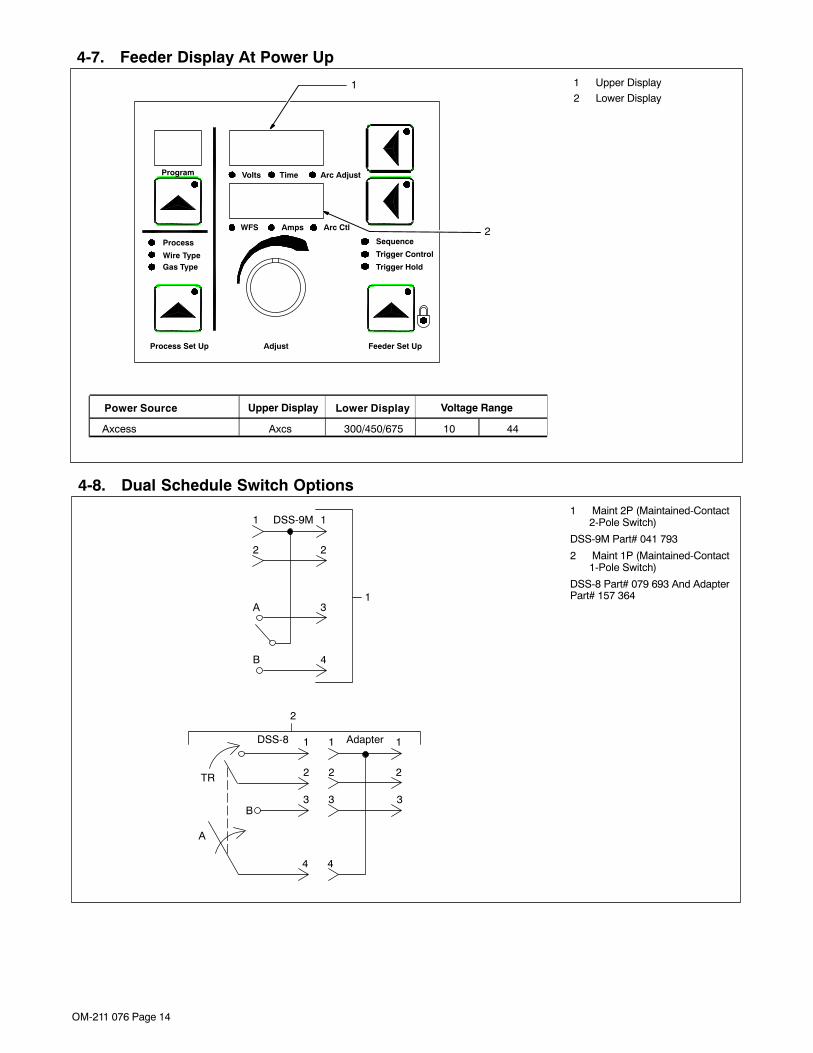
4-7. Feeder Display At Power Up1 Upper Display
2 Lower Display
Program
Process
Wire TypeGas Type
Trigger Control
Adjust
Volts Time
WFS Amps
Process Set Up Feeder Set Up
Trigger Hold
2
1
Power Source Upper Display Lower Display
Axcess Axcs 300/450/675 10 44
Voltage Range
Arc Adjust
Arc Ctl
Sequence
4-8. Dual Schedule Switch Options1 Maint 2P (Maintained-Contact
2-Pole Switch)
DSS-9M Part# 041 793
2 Maint 1P (Maintained-Contact1-Pole Switch)
DSS-8 Part# 079 693 And AdapterPart# 157 364
1 1
2 2
3 3
4
1
2
3
4
B
A
TR
Adapter
1
1 1
2 2
3A
4B
2
DSS-8
DSS-9M

OM-211 076 Page 15
SECTION 5 − OPERATION
5-1. Operational Terms
The following is a list of terms and their definitions as they apply to the interface unit in the wire feeder:
General Terms:
Arc Adjust Term used to represent arc length adjustments in pulse programs. Increasing Arc Adjust increasesthe actual arc length. Likewise, decreasing arc adjust shortens arc length. Arc Adjust is replaced byvolts in MIG programs.
Trigger Control Selecting Trigger Control allows activating trigger functions such as DS, TH, 4T, TDS, and TPS.
DS (Dual Schedule) Dual Schedule allows selecting a pair of programs that can be used together.
TH (Trigger Hold) Trigger Hold allows the operator to feed wire without continuously pressing the gun trigger. In triggerhold mode, momentarily press gun trigger, and wire will feed until gun trigger is momentarily pressedagain.
4T 4T allows the operator to select between weld parameters and crater parameters using the guntrigger. Crater time must be set for at least 0.2 seconds to make this function operational. If guntrigger is released during welding, unit goes into trigger hold, then pressing and holding trigger againcauses unit to stay in crater until trigger is released and crater parameter times out.
TDS (Trigger Dual Schedule) TDS allows the operator to select between a pair of weld programs by using the gun trigger. In TDSmode, momentarily pressing the gun trigger allows the operator to cycle between a pair of preselectedweld programs.
TPS (Trigger Program Schedule) TPS allows the operator to select weld programs by using the gun trigger. In TPS mode, momentarilypressing the gun trigger allows the operator to cycle through preselected weld programs up to a totalof 8 programs.
Program Eight active slots for selection of various processes, wire type, and parameters.
Process A selection made for MIG, Pulse, Accu-pulse, and RMD (optional).
MIG CV weld process with individual settings of voltage and wire speed.
Pulse Conventional pulse program using peak, background, pulse width, frequency, and peak voltage asfactory taught data. Adaptive method is controlled by frequency adjustment.
Accu-pulse Pulse process utilizing constant current ramps with constant voltage control of peaks andbackgrounds. Adaptive response is controlled by peak and minimum current levels. Benefits areshorter arc lengths, better puddle control, more tolerant of tip-to-work variation, less audible noise, noarc wandering, allows weld to fill in at toes increasing travel speed and deposition, and more tolerantto poor fit up and gaps.
RMD (optional) RMD refers to Regulated Metal Deposition. A precisely controlled short-circuit transfer. Benefits ofRMD are well suited to thin materials, improves gap filling and spatter reduction. Provides less heatinput into workpiece, minimizes distortion and allows use of larger diameter wire on thin gaugematerials.
Wire Type Selection of wire type by alloys and classification.
Gas Type Selection of shielding gas being used in application.
Process Set Up Selection procedure for entering program.
Program Load Enters selected program information into program slot.
Volts Preset voltage in MIG mode at idle, actual voltage while welding, and 3 seconds hold value at end ofweld.
Time Indicates time values being set for timed functions (e.g. Preflow, Postflow which are only available inthe Arc On and Analog input or the Arc On and No Analog input modes).
Arc Length Distance from end of wire electrode to workpiece.
WFS Term used to represent wire feed speed. In MIG mode, wire feed setting is independent of voltagesetting. In pulse, Accu-pulse, and RMD (optional) adjusting wire feed speed also increases powerlevel on wire electrode (one knob control).
Amps Indicates average amperage while welding and 3 seconds hold value at end of weld.
Arc Control Allows setting of inductance in MIG mode. In pulse and Accu-pulse mode, this adjustment changesthe arc cone by adjusting the preprogrammed factory pulse data. In RMD (optional), this control willaffect the in much the same way as inductance.
Inductance In short circuit GMAW welding, an increase in inductance will decrease the number of short circuittransfers per second (provided no other changes are made) and increase the arc-on time. Theincreased arc-on time makes the welding puddle more fluid.
Adjust Control knob used to change or set parameters and functions.
Sequence Selecting Sequence will allow setting of preflow, start, crater, and postflow times and parameters.
Preflow Setting a time value for gas flow prior to arc start.
Start Provides voltage/arc adjust, wire feed rate, and time value for modified arc starts (which is onlyadjustable with the optional PDA with File Management/WaveWriter software).

OM-211 076 Page 16
General Terms:
Crater Allows setting of voltage/arc adjust, wire feed rate, and time value for arc ends.
Postflow Setting a time value for gas flow after arc end.
Feeder Set Up Allow selection of Sequence and trigger functions.
Auto Thread Method of jogging wire without holding jog or trigger switch. Pressing Jog and Retract simultaneouslywill automatically feed wire. Default setting is 192 at a feed rate of 700 ipm (these values can bechanged using a PDA with File Management/WaveWriter software). Pressing jog, purge, or triggerswitch will terminate the auto-threading feature.
5-2. Power Switch1 Power Switch
1
803 504-A
OM-211 076 Page 17
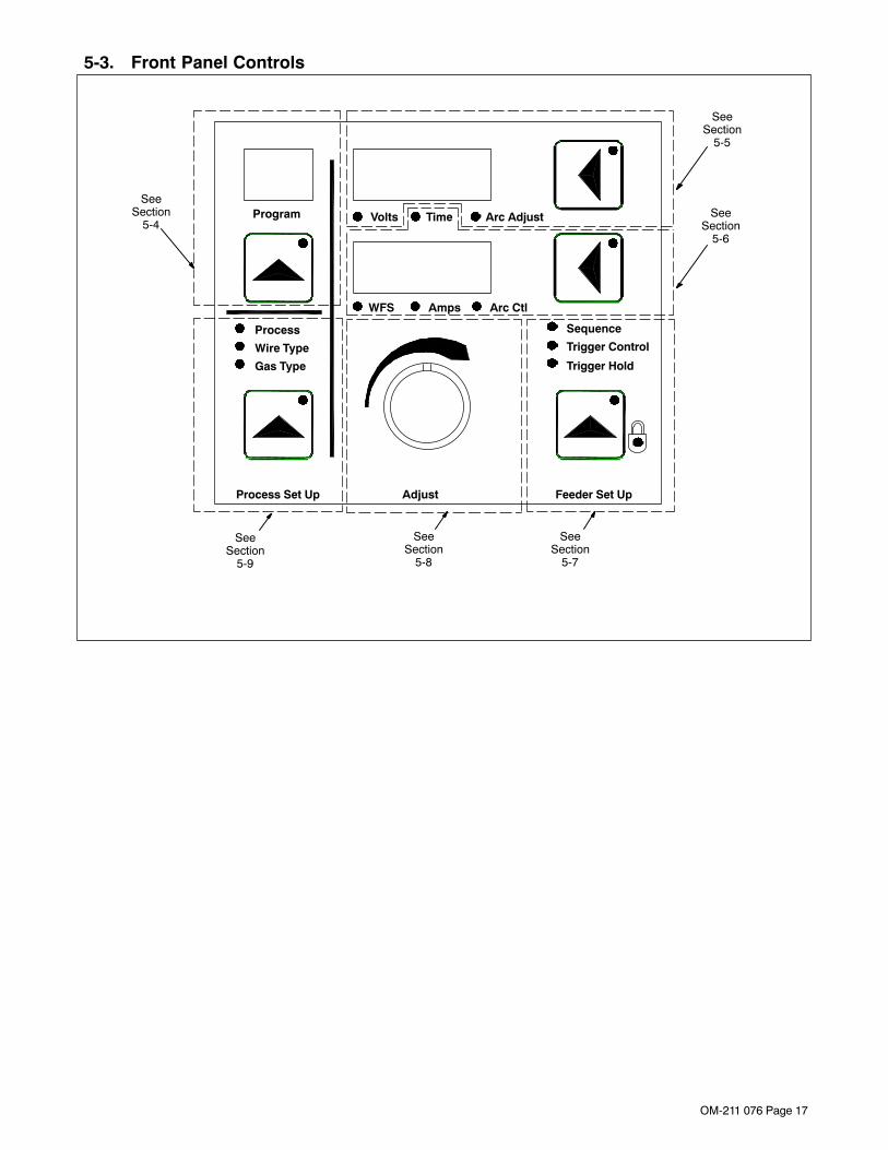
5-3. Front Panel Controls
SeeSection
5-5
SeeSection
5-6
SeeSection
5-9
SeeSection
5-8
SeeSection
5-7
SeeSection
5-4Program
Process
Wire Type
Gas Type
Trigger Control
Adjust
Volts Time
WFS Amps
Process Set Up Feeder Set Up
Trigger Hold
Arc Adjust
Arc Ctl
Sequence
OM-211 076 Page 18
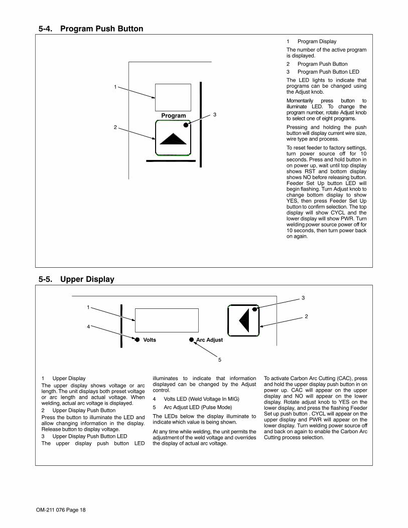
5-4. Program Push Button
1
3Program
2
1 Program Display
The number of the active programis displayed.
2 Program Push Button
3 Program Push Button LED
The LED lights to indicate thatprograms can be changed usingthe Adjust knob.
Momentarily press button toilluminate LED. To change theprogram number, rotate Adjust knobto select one of eight programs.
Pressing and holding the pushbutton will display current wire size,wire type and process.
To reset feeder to factory settings,turn power source off for 10seconds. Press and hold button inon power up, wait until top displayshows RST and bottom displayshows NO before releasing button.Feeder Set Up button LED willbegin flashing. Turn Adjust knob tochange bottom display to showYES, then press Feeder Set Upbutton to confirm selection. The topdisplay will show CYCL and thelower display will show PWR. Turnwelding power source power off for10 seconds, then turn power backon again.
5-5. Upper Display
2
1
4
3
1 Upper DisplayThe upper display shows voltage or arclength. The unit displays both preset voltageor arc length and actual voltage. Whenwelding, actual arc voltage is displayed.2 Upper Display Push ButtonPress the button to illuminate the LED andallow changing information in the display.Release button to display voltage.3 Upper Display Push Button LEDThe upper display push button LED
illuminates to indicate that informationdisplayed can be changed by the Adjustcontrol.
4 Volts LED (Weld Voltage In MIG)
5 Arc Adjust LED (Pulse Mode)
The LEDs below the display illuminate toindicate which value is being shown.
At any time while welding, the unit permits theadjustment of the weld voltage and overridesthe display of actual arc voltage.
To activate Carbon Arc Cutting (CAC), pressand hold the upper display push button in onpower up. CAC will appear on the upperdisplay and NO will appear on the lowerdisplay. Rotate adjust knob to YES on thelower display, and press the flashing FeederSet up push button . CYCL will appear on theupper display and PWR will appear on thelower display. Turn welding power source offand back on again to enable the Carbon ArcCutting process selection.
Volts Arc Adjust
5

OM-211 076 Page 19
5-6. Lower Display
21
5
4
3
WFS Amps Arc Ctl
6
Time7
1 Lower Display
The lower display shows WFS (wire feedspeed), AMPS (amperage), ARC CTL (arccontrol), or Time. The feeder displays onlypreset wire speed at idle (not welding). Whilewelding, the average amperage is displayed.The lower display shows welding sequencetime when the Time LED is illuminated.
2 WFS (Wire Feed Speed) LED
LED illuminates to indicate the preset wire feedvalue is being displayed and can be adjustedusing the Adjust knob.
3 Amps LED
LED illuminates to indicate the averageamperage is being displayed while weldingand for 3 seconds after welding is terminated.The amperage must be above a minimumvalue of 25 amps for this function to operate.
4 Arc Ctl (Arc Control) LEDLED illuminates to indicate that inductance(MIG) or ARC [Pulse, Accu-pulse, or RMD(optional)] is being displayed and can beadjusted using the Adjust knob.5 Time LEDLED illuminates to indicate that a time value isbeing displayed for a sequence function andcan be adjusted using the Adjust knob.6 Lower Display Push Button7 Lower Display Push Button LEDPressing the button illuminates the LED andselects either WFS or Arc Ctl value forchanging using the Adjust knob.To select Arc Ctl, press and hold lower displaybutton for 2 seconds. The top display will showeither INDU for a MIG program or ARC forPulse, Accu-pulse, or RMD (optional). To exitArc Ctl or INDU, either press the upper displaypush button or press and hold the lower displaypush button for 2 seconds.
During a welding program operation, it ispossible to change WFS (wire feed speed) byusing the Adjust knob regardless of the activeprogram sequence that appears on the dis-play.
When the Arc Ctl LED is illuminated, it ispossible to change values while welding byusing the Adjust knob. To return to actualvalues on the display, exit the Arc Ctl display.
� The lower display push button hasadditional functions when entering thesequence and trigger control functions(see Section 5-7).

OM-211 076 Page 20
5-7. Feeder Set Up Push Button
1 Feeder Set Up Push Button
2 Feeder Set Up Push Button LED
Press button to choose sequence, triggercontrol, or trigger hold.
3 Sequence LED
4 Trigger Control LED5 Trigger Hold LED
6 Lock LED (Access Allowed Only ByUsing An Optional PDA With FileManagement Software)
• When the Feeder Set Up button is pressedwhile in standby, the Feeder Set Up pushbutton LED illuminates and the top displaywill be active. Use the Adjust control toselect preflow (PRE), start (STRT), crater(CRTR), or postflow (POST) parameters.
• Press the lower display push button to allowthe bottom display to become active. Thetime LED will automatically begin flashing
and the unit will be in the time mode. Initially,all sequences will appear as off. Use theAdjust control display time and enable thetime sequence. Setting a time automaticallyenables a sequence. To turn off a sequence,change time setting to OFF.
• If the sequence has a voltage or arc adjustsetting, pressing the lower display pushbutton a second time will cause either voltsor arc adjust to appear on the display. Usethe Adjust control to set either parameter.
• If the sequence has a wire feed setting,pressing the lower display push button athird time will cause wfs to appear on thedisplay. Use the Adjust control to set wirespeed parameter.
• Press the lower display push button a fourthtime will cycle the display back to time.
• Press the Feeder Set Up button a secondtime to go to Trigger Control mode and allow
the top display to become active. Use theAdjust control to cycle through triggercontrol methods as follows: dual schedule,trigger hold, trigger dual schedule, programselect, 4T (see Section 5-1). The lowerdisplay will show the current state of eachtrigger control method as being either on oroff. Not all trigger control methods arecompatible with each other, and turning oncertain functions will cause other triggerfunctions to turn off.
• Press the lower display push button to allowthe bottom display to become active. Usethe Adjust control to turn selected triggercontrol methods on or off. If trigger hold isset to on, the trigger hold LED will illuminate.Note: if 4T is set to on, trigger hold willautomatically be set to on since thisparameter is necessary for the 4T function.
• Press the Feeder Set Up button a third timeto cycle back to standby mode.
16
3
4
Trigger Control
Feeder Set Up
Trigger Hold
Sequence
5
Welding Sequence Diagram
PreflowTime
StartTime
WeldTime Crater
Time
PostflowTime
2
5-8. Adjust Control
Adjust
1
1 Adjust Control
The Adjust control is used tochange various sequence parame-ters, and to select various se-quences. Refer to the section forthe function in question for informa-tion related to using the Adjust con-trol.

OM-211 076 Page 21
5-9. Process Set Up Push Button
• Press the Process Set Up push button thefirst time will illuminate the button LED andProcess LED above the button. Bothdisplays will show the current process and,if desired, these displays will be active toallow selecting a new process. Defaultprocesses are MIG, PULSE, and ACCUPULSE.
• Pressing the Process Set Up push button asecond time will illuminate the Wire TypeLED and the bottom display will show wiretypes available for the selected process. Tomake a selection, rotate the Adjust control.
• Pressing the Process Set Up push button athird time will keep Wire Type LED lit, but theupper display will be active and show wiresizes available for the current wire type. To
make a selection, rotate the Adjust control.
• Pressing the Process Set Up push button afourth time will illuminate the Gas Type LEDand both displays will show available gasselections for the process, and wire typeand wire size selection. To select an item,rotate the Adjust control.
• Pressing the Process Set Up push button afifth time will load the program that matchesthe selected parameters (process, wiretype, wire size, gas). The upper display willshow PROG and the lower display will showLOAD.
If no changes were made to any setup items,no program will be loaded, and unit will returnto standby mode.
If a custom program is loaded using anoptional PDA with File Management software,the upper display will show CUST and thelower display will show PROG. The Adjustcontrol remains active to allow loading astandard program in place of the customprogram.• Pressing and holding the Process Set Up
push button in on power up allows viewingthe software revisions of each circuit boardin the system. The top display shows theboard (PCM, UIM, WFCM, and AIM (auto-mated units only) and the lower displayshows the last 3 digits of the circuit boardpart number plus a letter designator. Pressthe flashing Feeder Set Up push button toexit the screen displays and continue thepower up process.
1
3
2
1 Process Set Up Push Button
2 Process Set Up LED
3 Program Selection LEDsProcess
Wire Type
Gas Type
Process Set Up
Table 5-1. Welding Wire And Gas Abbreviations*
Wire Description Wire Abbreviation Alloy Type Gas Type Gas Abbreviation
Steel STL E70, E100, E120 100% CO2,90% Argon/10% CO2,85% Argon/15% CO2,75% Argon/25% CO2,95% Argon/5% CO2,95% Argon /5% O2,98% Argon/2% O2
CO2C10C15C25C5
OX5OX2
Stainless Steel SS 308, 309, 312, 316 98% Argon, 2% O2(81Ar/18HE/1CO2
Accu-pulse)90HE/7-1/2Ar/2-1/2CO2MIG/RMD/Accu-pulse)
OX2Tri Gas
Tri Gas
Cored Tubular Wire MCOR 71, 76, 86R, 409,439
90% Argon/10% CO2 C10439 98% Argon/2% O2 OX2
Aluminum ALUM 4XXX, 5XXX 100% Argon ARGN
* Not all wire types may be available with your unit.

OM-211 076 Page 22
5-10. Jog/Purge
Pressing the Jog/Purge switch allows theoperator to jog wire without energizing theweld power or gas valve circuit.
• The unit provides the ability to jog the wirefeeder by means of the gun trigger or theJog/Purge switch. If the welding arc doesnot initiate in 3 seconds after the gun triggeris activated, the unit will perform a jogoperation for a maximum of 30 seconds. Ifthe gun trigger is still activated after 30seconds, the jog operation is terminated toprevent complete unspooling of the wire, inthe case of a damaged gun. The unit
displays the “ERR STRT“ message toinform the operator that the trigger isactivated.
• Jog speed can be adjusted by the Adjustcontrol when the unit is jogging wire. Theunit displays jog speed when the unit isbeing jogged.
• Jogging can also be accomplished bypressing the Jog/Purge button.
• Pressing the Jog/Purge button also allowsthe operator to purge gas lines before
welding and to preset gas pressure at theregulator.
• This unit is equipped with Auto Threadcapability. By rocking the switch from purgeto jog within 0.5 seconds will automaticallyfeed wire for a factory default setting of 192in (4877 mm) of wire before stopping. Thedefault feed rate is 700 ipm. These settingscan be changed using an optional PDA withFile Management software. Pressing theJog/Purge switch or gun trigger during AutoThreading will terminate the automatic feedoperation.
1
803 505-A
2
3
1 Jog/Purge Push Button
2 Adjust Control
3 Gun Trigger Receptacle

OM-211 076 Page 23
5-11. Reset Mode
198 993 / 803 504-A
� Reset mode is not active whenProgram Lock is enabled.
The reset mode allows the operator toreload factory program settings for alleight active programs in the unit.
� System configuration data will belost during the Reset operation.
Enter reset mode by turning power On and pressingthe Program Push Button until the RST NO messageis displayed. RST NO message will not display until
after the power-up sequence is completed(approximately 20 seconds).
Rotate Adjust knob to change NOto YES.
Program 1 Pulse.035 Mild Steel90% Argon, 10% CO2
Program 2 MIG.035 Mild Steel75% Argon, 25% CO2
Program 3 Accu-pulse.035 Mild Steel90% Argon, 10% O2
Program 4 Pulse.045 Mild Steel90% Argon, 10% CO2
Program 5 MIG.045 Mild Steel75% Argon, 25% CO2
Program 6 Accu-pulse.045 Mild Steel90% Argon, 10% O2
Program 7 Pulse.052 Mild Steel90% Argon, 10% CO2
Program 8 MIG.052 Mild Steel75% Argon, 25% CO2
Press the Arc Control button toconfirm the reset.
The reset message is displayed for2 seconds while factory program
settings are being reloaded.
During the reset mode the followingfactory default programs are loaded
into the unit:
Cycl Pwr message appears on the displaywhen programs complete loading.
Turn power off, wait 10 seconds, and turnpower back on again to complete the reset
operation.
� After Reset is complete, be sure to loadappropriate programs that contain thecorrect wire size, process, and shielding gasfor the welding operation
RST
NOTrigger Control
Program
ProcessWire TypeGas Type
Process Set up
Volts Time Arc Adjust
WFS Amps Arc CtlSequence
Trigger Hold
Adjust Feeder Set Up
Trigger Control
Program
ProcessWire TypeGas Type
Process Set up
Volts Time Arc Adjust
WFS Amps Arc CtlSequence
Trigger Hold
Adjust Feeder Set Up
RST
YESTrigger Control
Program
ProcessWire TypeGas Type
Process Set up
Volts Time Arc Adjust
WFS Amps Arc CtlSequence
Trigger Hold
Adjust Feeder Set Up
RST
YESTrigger Control
Program
ProcessWire TypeGas Type
Process Set up
Volts Time Arc Adjust
WFS Amps Arc CtlSequence
Trigger Hold
Adjust Feeder Set Up
CYCL
PWR

OM-211 076 Page 24
SECTION 6 − SETTING SEQUENCE PARAMETERS
6-1. Sequence Parameters In A Program
� For more information onSequence mode, see FeederSet Up Push Button in Section5-7.
If time is set to Off in Weldsequence, welding continues untilgun trigger is released.
If time is set to zero in any timedsequence except Weld, thesequence is skipped.
� Maximum IPM may actuallybe lower depending on wiresize and gas combination.
TriggerPressed
TriggerReleased
Time
StartTime
Preflow
Weld
CraterTime
Postflow
Start
Time Time
PostflowCraterWeld
Preflow
SequenceEnd
Volts/Trim IPM Seconds
2. Postflow Off-5.0
X = Setting available.
1. Preflow Off-5.0
Sequence Parameters
3. Start
4. Crater
Off-5.0
Off-5.0
10.0-44.0/0-99
40-1400/0-99
10.0-44.0/0-99
40-1400/0-99
OM-211 076 Page 25
SECTION 7 − MAINTENANCE
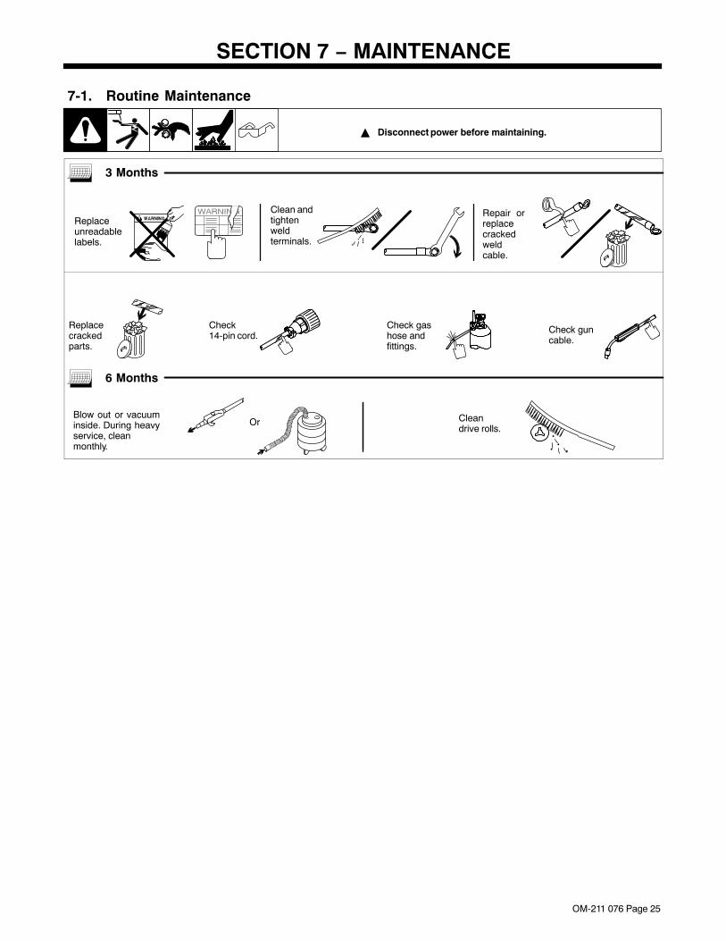
7-1. Routine Maintenance
� Disconnect power before maintaining.
3 Months
Replaceunreadablelabels.
Clean andtightenweldterminals.
Repair orreplacecrackedweldcable.
Check14-pin cord.
Check gashose andfittings.
Check guncable.
Replacecrackedparts.
6 Months
Blow out or vacuuminside. During heavyservice, cleanmonthly.
Or Cleandrive rolls.

OM-211 076 Page 26
7-2. Diagnostics
ERR SENS
• The voltage sense error indicates novoltage sensing feedback signal. Checkconnections at feeder and welding powersource. Press Jog/Purge button to clearerror.
ERR TACH
• The tach error occurs 2 seconds after theloss of tachometer feedback. The motorspeed is regulated through the monitoring ofvoltage and current. Press Jog/Purgebutton to clear error.
ERR MOTR
• The motor error indicates that the motorhas been drawing too much current for toolong. To remedy this, reduce the wire feedspeed or the wire feeder torque load/dutycycle. Press Jog/Purge button to clear error.
ERR WFS
• The wire feed speed error indicates actualwire feed speed does not match wire feedspeed command. Press Jog/Purge buttonto clear error.
ERR STRT• The start error occurs if the user has the
trigger held for more than two minuteswithout striking an arc, or if the user holdsthe trigger past the postflow phase in atimed weld. This error also occurs if thetrigger is held when the feeder is poweredup. The error may be cleared by releasingthe trigger, and pressing the Jog/Purgebutton.
ERR STOP• The stop error occurs as result of
obstructions in the wire feed system or afaulty wire drive system. Check wire feedand wire drive systems. Press Jog/Purgebutton to clear error.
ERR FLOW• The flow error indicates no gas flow to the
gun. The error may be reset byreestablishing gas flow to the gun, and thenpressing the Jog/Purge button.
ERR COOL• The cool error indicates no coolant flow in
water flow switch option. The error may bereset by reestablishing coolant flow to thegun, and then pressing the Jog/Purgebutton.
ERR FTP
• The file transfer error occurs if data doesnot transfer to the feeder correctly. PressJog/Purge button to clear error, and transferdata to feeder again.
ERR GND
• The ground current error occurs if weldcurrent is detected in the earth groundconnection. May be caused by a conductormaking contact with unit chassis. Checkand repair feeder weld connections. PressJog/Purge button to clear error.
ERR STUK
• The stuck error occurs if the welding wiresticks to the workpiece at the end of a weld.May be caused by poor weld conditions.The error may be cleared by cutting wirefrom workpiece, and pressing the Jog/Purge button.
ERR PSF
• The primary power error occurs if theprimary power circuit inside the feeder is notfunctioning correctly. Check feederconnections. Press Jog/Purge button toclear error.
ERR
SENS
ERR
TACH
ERR
MOTR
ERR
WFS
The following error messages are shown on theupper and lower displays to indicate specific errors.Explanations are in the text below:
ERR
STRT
ERR
STOPIndicates a voltagesense error.
Indicates atachometer error.
Indicates a motorerror.
Indicates a wirefeed speed error.
Indicates an arcstart error.
Indicates an arcstop error.
ERR
FLOW
ERR
COOL
ERR
FTP
ERR
GND
ERR
STUK
ERR
PSFIndicates a gasflow error.
Indicates a coolantflow error.
Indicates a filetransfer point error.
Indicates a groundcurrent error.
Indicates a wirestuck error.
Indicates a primarypower error.
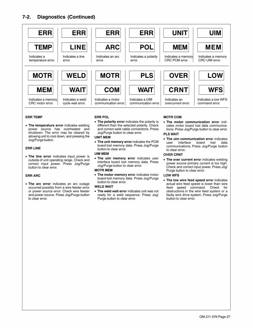
OM-211 076 Page 27
7-2. Diagnostics (Continued)
ERR TEMP
• The temperature error indicates weldingpower source has overheated andshutdown. The error may be cleared byallowing unit to cool down, and pressing theJog/Purge button.
ERR LINE
• The line error indicates input power isoutside of unit operating range. Check andcorrect input power. Press Jog/Purgebutton to clear error.
ERR ARC
• The arc error indicates an arc outageoccurred possibly from a wire feeder erroror power source error. Check wire feederand power source. Press Jog/Purge buttonto clear error.
ERR POL• The polarity error indicates the polarity is
different than the selected polarity. Checkand correct weld cable connections. PressJog/Purge button to clear error.
UNIT MEM• The unit memory error indicates the PCM
board lost memory data. Press Jog/Purgebutton to clear error.
UIM MEM• The uim memory error indicates user
interface board lost memory data. PressJog/Purge button to clear error.
MOTR MEM• The motor memory error indicates motor
board lost memory data. Press Jog/Purgebutton to clear error.
WELD WAIT• The weld wait error indicates unit was not
ready for a weld sequence. Press Jog/Purge button to clear error.
MOTR COM• The motor communication error indi-
cates motor board lost data communica-tions. Press Jog/Purge button to clear error.
PLS WAIT• The uim communication error indicates
user interface board lost datacommunications. Press Jog/Purge buttonto clear error.
OVER CRNT• The over current error indicates welding
power source primary current is too high.Check and correct input power. Press Jog/Purge button to clear error.
LOW WFS• The low wire feed speed error indicates
actual wire feed speed is lower than wirefeed speed command. Check forobstructions in the wire feed system or afaulty wire drive system. Press Jog/Purgebutton to clear error.
UNIT
MEM
UIM
MEM
MOTR
MEM
WELD
WAIT
MOTR
COM
PLS
WAIT
Indicates a memoryCRC PCM error.
Indicates a memoryCRC UIM error.
Indicates a memoryCRC motor error.
Indicates a weldcycle wait error.
Indicates a motorcommunication error.
Indicates a UIMcommunication error.
OVER
CRNT
LOW
WFSIndicates anovercurrent error.
Indicates a low WFScommand error.
ERR
TEMP
ERR
LINE
ERR
ARC
ERR
POLIndicates atemperature error.
Indicates a lineerror.
Indicates an arcerror.
Indicates a polarityerror.

OM-211 076 Page 28
7-2. Diagnostics (Continued)
RMD DONE
• The RMD done message indicates theRMD demo is completed. PressingJog/Purge button will change the screen toCYCL PWR on the display. Turn unit poweroff and back on again.
OVER AVER
• The over average error indicates thatcurrent is outside the average range for theset program parameters. Check and correctprogram parameters. Press Jog/Purgebutton to clear error.
UNIT COMM
• The unit communication error indicatesthe data bus on the PCM board is notfunctioning properly. Press Jog/Purgebutton to clear error.
REL TRIG
• The release trigger error indicates theuser held the gun trigger after a timed weldwas completed causing the contactor toremain on. Press Jog/Purge button to clearerror.
TRIG STUK
• The trigger stuck error indicates the userheld the gun trigger during power up. PressJog/Purge button to clear error.
ERR UNKN
• The unknown error indicates amalfunction in the system somewhere.Press Jog/Purge button to clear error.
UNIT
COMM
ERR
UNKNIndicates a CRCPCM bus error.
Indicates anunknown error.
RMD
DONE
OVER
AVERIndicates RMDdemo is done.
Indicates an overaverage current error.
REL
TRIGIndicates a contactoron error.
TRIG
STUKIndicates a triggerclosed error.

OM-211 076 Page 29
7-3. Troubleshooting
� Disconnect power before troubleshooting
Trouble Remedy
Wire feeds, shielding gas flows, butelectrode wire is not energized.
Check and secure weld cable connections (see Section 4-2).
Electrode wire feeding stops or feedserratically during welding
Check gun trigger connection. See gun Owner’s Manual.erratically during welding.
Check gun trigger. See gun Owner’s Manual.
Readjust hub tension and drive roll pressure (see Section 4-6).
Change to correct size drive roll (see Table 9-1).
Clean or replace dirty or worn drive roll.
Incorrect size or worn wire guides.
Replace contact tip or liner. See gun Owner’s Manual.
Remove weld spatter or foreign matter from around nozzle opening.
Have Factory Authorized Service Agency check drive motor or motor control board PC1.
Motor runs slowly. Check for correct input voltage.
Wire feeder power is on, displays lightup, but unit is inoperative.
Check welding gun trigger leads for continuity, and repair leads or replace gun.

OM-211 076 Page 30
SECTION 8 − ELECTRICAL DIAGRAM
Figure 8-1. Circuit Diagram
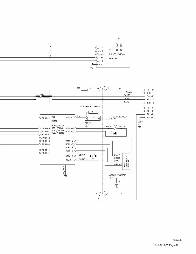
OM-211 076 Page 31
211 005-D
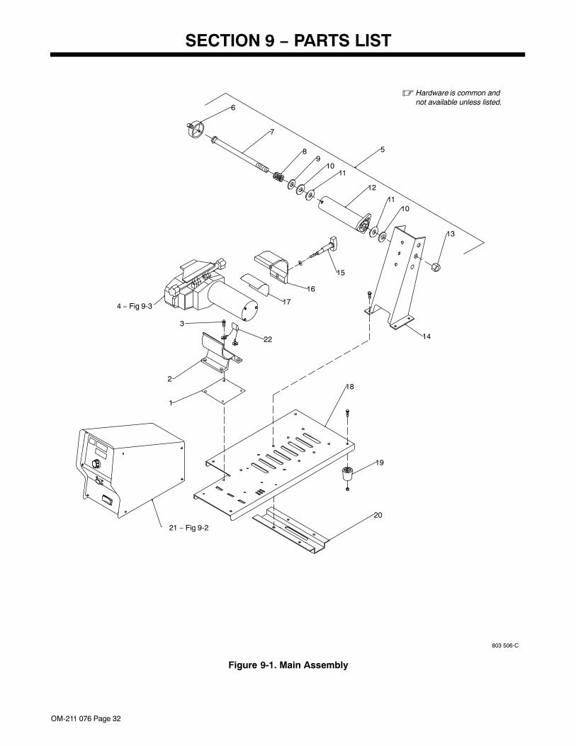
OM-211 076 Page 32
SECTION 9 − PARTS LIST
803 506-C
� Hardware is common andnot available unless listed.
12
18
20
2
1
3
16
17
7
15
8
11
910
6
19
14
1110
13
5
22
4 − Fig 9-3
21 − Fig 9-2
Figure 9-1. Main Assembly
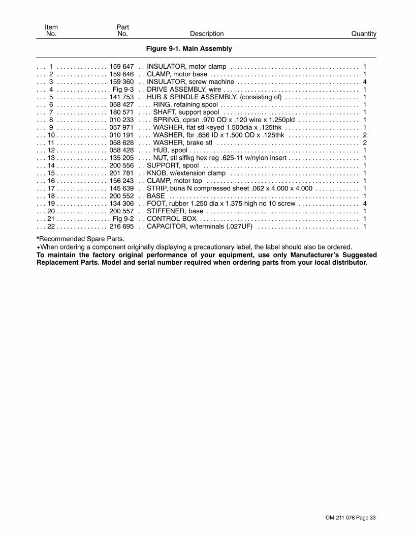
OM-211 076 Page 33
DescriptionPartNo.
ItemNo.
Figure 9-1. Main Assembly
Quantity
1 159 647 INSULATOR, motor clamp 1. . . . . . . . . . . . . . . . . . . . . . . . . . . . . . . . . . . . . . . . . . . . . . . . . . . . . . . . . . 2 159 646 CLAMP, motor base 1. . . . . . . . . . . . . . . . . . . . . . . . . . . . . . . . . . . . . . . . . . . . . . . . . . . . . . . . . . . . . . . . 3 159 360 INSULATOR, screw machine 4. . . . . . . . . . . . . . . . . . . . . . . . . . . . . . . . . . . . . . . . . . . . . . . . . . . . . . . . 4 Fig 9-3 DRIVE ASSEMBLY, wire 1. . . . . . . . . . . . . . . . . . . . . . . . . . . . . . . . . . . . . . . . . . . . . . . . . . . . . . . . . . . . . 5 141 753 HUB & SPINDLE ASSEMBLY, (consisting of) 1. . . . . . . . . . . . . . . . . . . . . . . . . . . . . . . . . . . . . . . . . . 6 058 427 RING, retaining spool 1. . . . . . . . . . . . . . . . . . . . . . . . . . . . . . . . . . . . . . . . . . . . . . . . . . . . . . . . . . . . . . . 7 180 571 SHAFT, support spool 1. . . . . . . . . . . . . . . . . . . . . . . . . . . . . . . . . . . . . . . . . . . . . . . . . . . . . . . . . . . . . . 8 010 233 SPRING, cprsn .970 OD x .120 wire x 1.250pld 1. . . . . . . . . . . . . . . . . . . . . . . . . . . . . . . . . . . . . . . . 9 057 971 WASHER, flat stl keyed 1.500dia x .125thk 1. . . . . . . . . . . . . . . . . . . . . . . . . . . . . . . . . . . . . . . . . . . .
10 010 191 WASHER, fbr .656 ID x 1.500 OD x .125thk 2. . . . . . . . . . . . . . . . . . . . . . . . . . . . . . . . . . . . . . . . . . . 11 058 628 WASHER, brake stl 2. . . . . . . . . . . . . . . . . . . . . . . . . . . . . . . . . . . . . . . . . . . . . . . . . . . . . . . . . . . . . . . . 12 058 428 HUB, spool 1. . . . . . . . . . . . . . . . . . . . . . . . . . . . . . . . . . . . . . . . . . . . . . . . . . . . . . . . . . . . . . . . . . . . . . . . 13 135 205 NUT, stl slflkg hex reg .625-11 w/nylon insert 1. . . . . . . . . . . . . . . . . . . . . . . . . . . . . . . . . . . . . . . . . . . 14 200 556 SUPPORT, spool 1. . . . . . . . . . . . . . . . . . . . . . . . . . . . . . . . . . . . . . . . . . . . . . . . . . . . . . . . . . . . . . . . . . 15 201 781 KNOB, w/extension clamp 1. . . . . . . . . . . . . . . . . . . . . . . . . . . . . . . . . . . . . . . . . . . . . . . . . . . . . . . . . . 16 156 243 CLAMP, motor top 1. . . . . . . . . . . . . . . . . . . . . . . . . . . . . . . . . . . . . . . . . . . . . . . . . . . . . . . . . . . . . . . . . 17 145 639 STRIP, buna N compressed sheet .062 x 4.000 x 4.000 1. . . . . . . . . . . . . . . . . . . . . . . . . . . . . . . . . 18 200 552 BASE 1. . . . . . . . . . . . . . . . . . . . . . . . . . . . . . . . . . . . . . . . . . . . . . . . . . . . . . . . . . . . . . . . . . . . . . . . . . . . 19 134 306 FOOT, rubber 1.250 dia x 1.375 high no 10 screw 4. . . . . . . . . . . . . . . . . . . . . . . . . . . . . . . . . . . . . . 20 200 557 STIFFENER, base 1. . . . . . . . . . . . . . . . . . . . . . . . . . . . . . . . . . . . . . . . . . . . . . . . . . . . . . . . . . . . . . . . . 21 Fig 9-2 CONTROL BOX 1. . . . . . . . . . . . . . . . . . . . . . . . . . . . . . . . . . . . . . . . . . . . . . . . . . . . . . . . . . . . . . . . . . . . 22 216 695 CAPACITOR, w/terminals (.027UF) 1. . . . . . . . . . . . . . . . . . . . . . . . . . . . . . . . . . . . . . . . . . . . . . . . . .
*Recommended Spare Parts.+When ordering a component originally displaying a precautionary label, the label should also be ordered.To maintain the factory original performance of your equipment, use only Manufacturer’s SuggestedReplacement Parts. Model and serial number required when ordering parts from your local distributor.
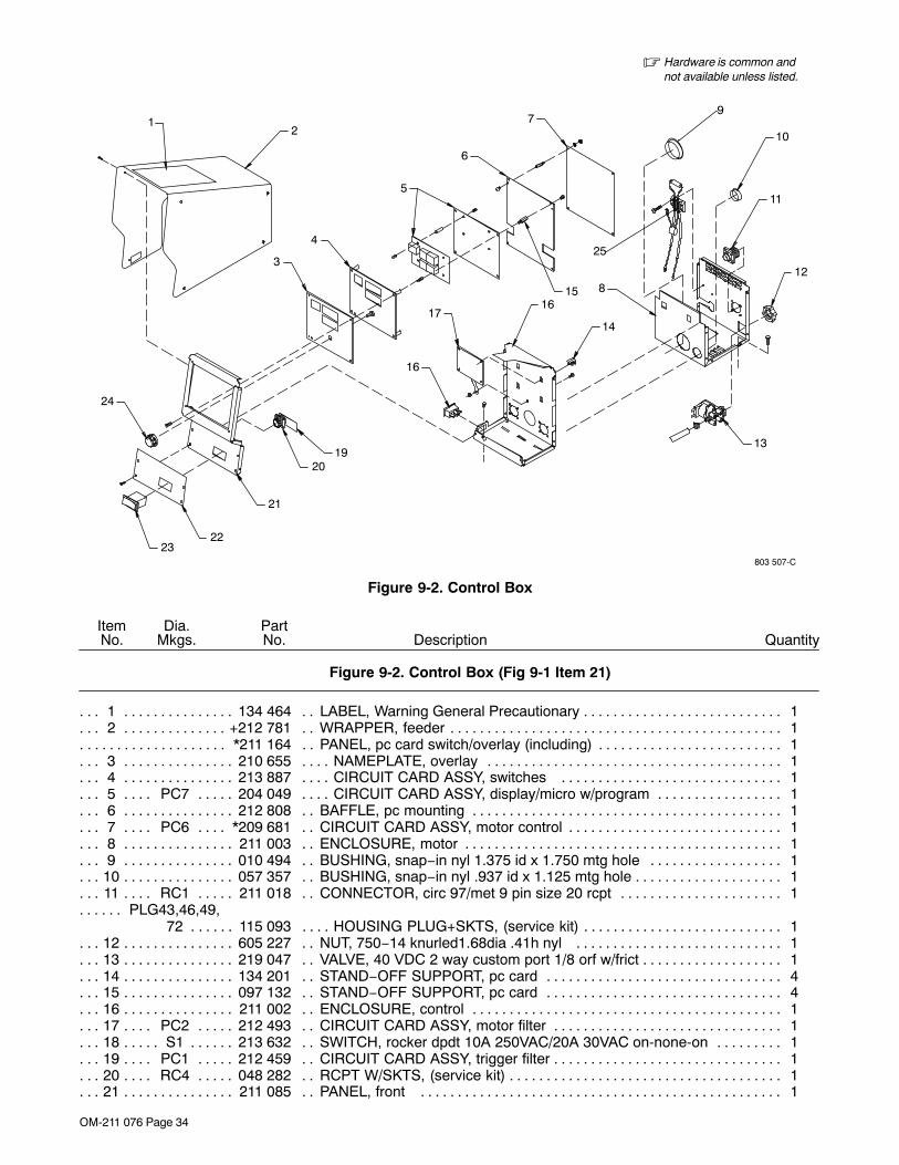
OM-211 076 Page 34
803 507-C
� Hardware is common andnot available unless listed.
2
3
4
5
6
79
10
11
812
13
14
1617
16
1920
21
2223
24
25
1
15
Figure 9-2. Control Box
DescriptionPartNo.
Dia.Mkgs.
ItemNo.
Figure 9-2. Control Box (Fig 9-1 Item 21)
Quantity
1 134 464 LABEL, Warning General Precautionary 1. . . . . . . . . . . . . . . . . . . . . . . . . . . . . . . . . . . . . . . . . . . . . . . 2 +212 781 WRAPPER, feeder 1. . . . . . . . . . . . . . . . . . . . . . . . . . . . . . . . . . . . . . . . . . . . . . . . . . . . . . . . . . . . . . . .
*211 164 PANEL, pc card switch/overlay (including) 1. . . . . . . . . . . . . . . . . . . . . . . . . . . . . . . . . . . . . . . . . . . . . . . 3 210 655 NAMEPLATE, overlay 1. . . . . . . . . . . . . . . . . . . . . . . . . . . . . . . . . . . . . . . . . . . . . . . . . . . . . . . . . . . . . . 4 213 887 CIRCUIT CARD ASSY, switches 1. . . . . . . . . . . . . . . . . . . . . . . . . . . . . . . . . . . . . . . . . . . . . . . . . . . . 5 PC7 204 049 CIRCUIT CARD ASSY, display/micro w/program 1. . . . . . . . . . . . . . . . . . . . . . . . . . . . . . . . . 6 212 808 BAFFLE, pc mounting 1. . . . . . . . . . . . . . . . . . . . . . . . . . . . . . . . . . . . . . . . . . . . . . . . . . . . . . . . . . . . . . 7 PC6 *209 681 CIRCUIT CARD ASSY, motor control 1. . . . . . . . . . . . . . . . . . . . . . . . . . . . . . . . . . . . . . . . . . 8 211 003 ENCLOSURE, motor 1. . . . . . . . . . . . . . . . . . . . . . . . . . . . . . . . . . . . . . . . . . . . . . . . . . . . . . . . . . . . . . . 9 010 494 BUSHING, snap−in nyl 1.375 id x 1.750 mtg hole 1. . . . . . . . . . . . . . . . . . . . . . . . . . . . . . . . . . . . . .
10 057 357 BUSHING, snap−in nyl .937 id x 1.125 mtg hole 1. . . . . . . . . . . . . . . . . . . . . . . . . . . . . . . . . . . . . . . . 11 RC1 211 018 CONNECTOR, circ 97/met 9 pin size 20 rcpt 1. . . . . . . . . . . . . . . . . . . . . . . . . . . . . . . . . . . .
PLG43,46,49,. . . . . . 72 115 093 HOUSING PLUG+SKTS, (service kit) 1. . . . . . . . . . . . . . . . . . . . . . . . . . . . . . . . . . . . .
12 605 227 NUT, 750−14 knurled1.68dia .41h nyl 1. . . . . . . . . . . . . . . . . . . . . . . . . . . . . . . . . . . . . . . . . . . . . . . . 13 219 047 VALVE, 40 VDC 2 way custom port 1/8 orf w/frict 1. . . . . . . . . . . . . . . . . . . . . . . . . . . . . . . . . . . . . . . 14 134 201 STAND−OFF SUPPORT, pc card 4. . . . . . . . . . . . . . . . . . . . . . . . . . . . . . . . . . . . . . . . . . . . . . . . . . . . 15 097 132 STAND−OFF SUPPORT, pc card 4. . . . . . . . . . . . . . . . . . . . . . . . . . . . . . . . . . . . . . . . . . . . . . . . . . . . 16 211 002 ENCLOSURE, control 1. . . . . . . . . . . . . . . . . . . . . . . . . . . . . . . . . . . . . . . . . . . . . . . . . . . . . . . . . . . . . . 17 PC2 212 493 CIRCUIT CARD ASSY, motor filter 1. . . . . . . . . . . . . . . . . . . . . . . . . . . . . . . . . . . . . . . . . . . . . 18 S1 213 632 SWITCH, rocker dpdt 10A 250VAC/20A 30VAC on-none-on 1. . . . . . . . . . . . . . . . . . . . . . . . . 19 PC1 212 459 CIRCUIT CARD ASSY, trigger filter 1. . . . . . . . . . . . . . . . . . . . . . . . . . . . . . . . . . . . . . . . . . . . . 20 RC4 048 282 RCPT W/SKTS, (service kit) 1. . . . . . . . . . . . . . . . . . . . . . . . . . . . . . . . . . . . . . . . . . . . . . . . . . . 21 211 085 PANEL, front 1. . . . . . . . . . . . . . . . . . . . . . . . . . . . . . . . . . . . . . . . . . . . . . . . . . . . . . . . . . . . . . . . . . . . .
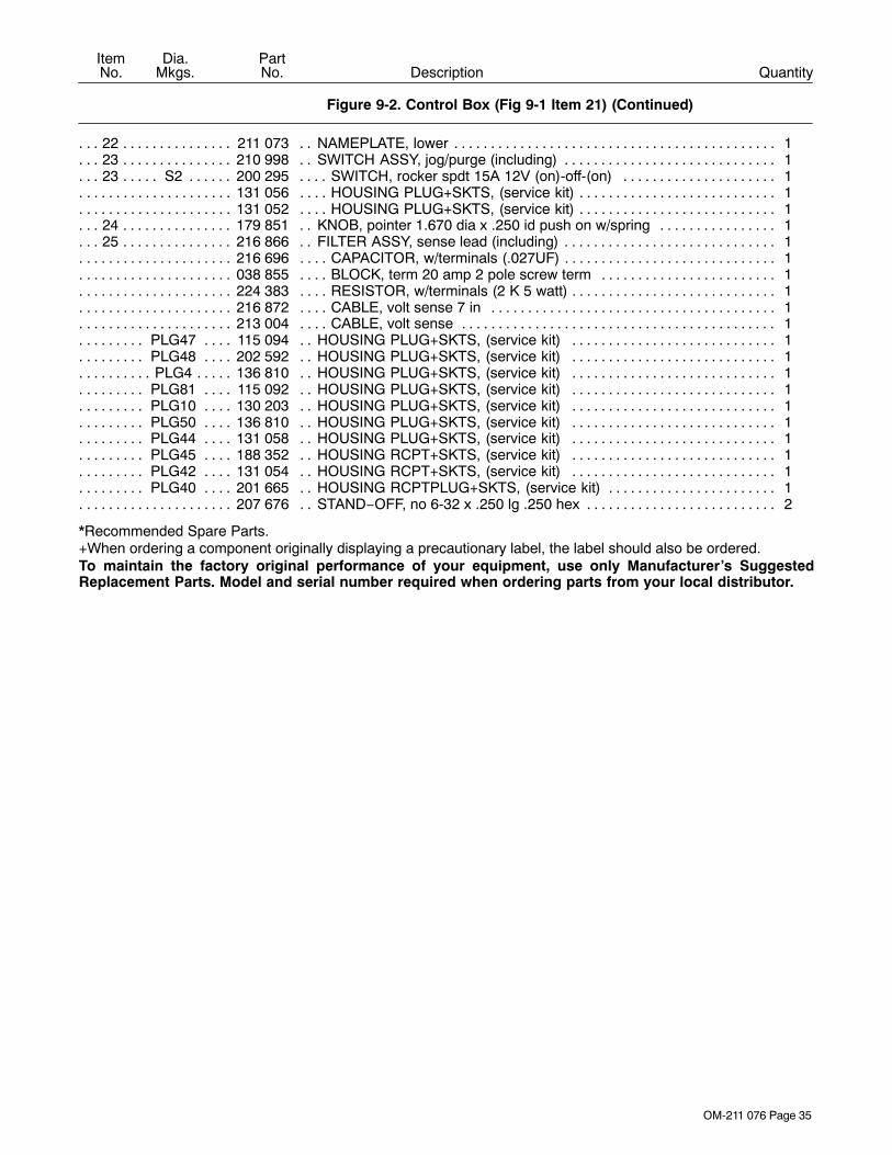
OM-211 076 Page 35
DescriptionPartNo.
Dia.Mkgs.
ItemNo.
Figure 9-2. Control Box (Fig 9-1 Item 21) (Continued)
Quantity
22 211 073 NAMEPLATE, lower 1. . . . . . . . . . . . . . . . . . . . . . . . . . . . . . . . . . . . . . . . . . . . . . . . . . . . . . . . . . . . . . . . 23 210 998 SWITCH ASSY, jog/purge (including) 1. . . . . . . . . . . . . . . . . . . . . . . . . . . . . . . . . . . . . . . . . . . . . . . . . 23 S2 200 295 SWITCH, rocker spdt 15A 12V (on)-off-(on) 1. . . . . . . . . . . . . . . . . . . . . . . . . . . . . . . . . . . . . . .
131 056 HOUSING PLUG+SKTS, (service kit) 1. . . . . . . . . . . . . . . . . . . . . . . . . . . . . . . . . . . . . . . . . . . . . . . . . . . . 131 052 HOUSING PLUG+SKTS, (service kit) 1. . . . . . . . . . . . . . . . . . . . . . . . . . . . . . . . . . . . . . . . . . . . . . . . . . . .
24 179 851 KNOB, pointer 1.670 dia x .250 id push on w/spring 1. . . . . . . . . . . . . . . . . . . . . . . . . . . . . . . . . . . . 25 216 866 FILTER ASSY, sense lead (including) 1. . . . . . . . . . . . . . . . . . . . . . . . . . . . . . . . . . . . . . . . . . . . . . . . .
216 696 CAPACITOR, w/terminals (.027UF) 1. . . . . . . . . . . . . . . . . . . . . . . . . . . . . . . . . . . . . . . . . . . . . . . . . . . . . . 038 855 BLOCK, term 20 amp 2 pole screw term 1. . . . . . . . . . . . . . . . . . . . . . . . . . . . . . . . . . . . . . . . . . . . . . . . . 224 383 RESISTOR, w/terminals (2 K 5 watt) 1. . . . . . . . . . . . . . . . . . . . . . . . . . . . . . . . . . . . . . . . . . . . . . . . . . . . . 216 872 CABLE, volt sense 7 in 1. . . . . . . . . . . . . . . . . . . . . . . . . . . . . . . . . . . . . . . . . . . . . . . . . . . . . . . . . . . . . . . . 213 004 CABLE, volt sense 1. . . . . . . . . . . . . . . . . . . . . . . . . . . . . . . . . . . . . . . . . . . . . . . . . . . . . . . . . . . . . . . . . . . .
PLG47 115 094 HOUSING PLUG+SKTS, (service kit) 1. . . . . . . . . . . . . . . . . . . . . . . . . . . . . . . . . . . . . . . . . . . PLG48 202 592 HOUSING PLUG+SKTS, (service kit) 1. . . . . . . . . . . . . . . . . . . . . . . . . . . . . . . . . . . . . . . . . . . PLG4 136 810 HOUSING PLUG+SKTS, (service kit) 1. . . . . . . . . . . . . . . . . . . . . . . . . . . . . . . . . . . . . . . . . . . . .
PLG81 115 092 HOUSING PLUG+SKTS, (service kit) 1. . . . . . . . . . . . . . . . . . . . . . . . . . . . . . . . . . . . . . . . . . . PLG10 130 203 HOUSING PLUG+SKTS, (service kit) 1. . . . . . . . . . . . . . . . . . . . . . . . . . . . . . . . . . . . . . . . . . . PLG50 136 810 HOUSING PLUG+SKTS, (service kit) 1. . . . . . . . . . . . . . . . . . . . . . . . . . . . . . . . . . . . . . . . . . . PLG44 131 058 HOUSING PLUG+SKTS, (service kit) 1. . . . . . . . . . . . . . . . . . . . . . . . . . . . . . . . . . . . . . . . . . . PLG45 188 352 HOUSING RCPT+SKTS, (service kit) 1. . . . . . . . . . . . . . . . . . . . . . . . . . . . . . . . . . . . . . . . . . . PLG42 131 054 HOUSING RCPT+SKTS, (service kit) 1. . . . . . . . . . . . . . . . . . . . . . . . . . . . . . . . . . . . . . . . . . . PLG40 201 665 HOUSING RCPTPLUG+SKTS, (service kit) 1. . . . . . . . . . . . . . . . . . . . . . . . . . . . . . . . . . . . . .
207 676 STAND−OFF, no 6-32 x .250 lg .250 hex 2. . . . . . . . . . . . . . . . . . . . . . . . . . . . . . . . . . . . . . . . . . . . . . . . .
*Recommended Spare Parts.+When ordering a component originally displaying a precautionary label, the label should also be ordered.To maintain the factory original performance of your equipment, use only Manufacturer’s SuggestedReplacement Parts. Model and serial number required when ordering parts from your local distributor.

OM-211 076 Page 36
See Table 9-1 For Drive Roll & Wire Guide Kits
� Hardware is common andnot available unless listed.
802 950-B
9
29
28
35
3031
32
27 34
26
33
2322
2524
21
1
432
5 6 87
45
1
23
6
16
15
20
10
15
1318
11
12
14
19
18
17
Figure 9-3. Drive Assembly, Wire
DescriptionPartNo.
Dia.Mkgs.
ItemNo.
Figure 9-3. Drive Assembly, Wire (Fig 9-1 Item 4)
Quantity
1 010 668 SCREW, cap stl sch .250-20 x 1.500 4. . . . . . . . . . . . . . . . . . . . . . . . . . . . . . . . . . . . . . . . . . . . . . . . . . 2 172 075 CARRIER, drive roll w/components 4. . . . . . . . . . . . . . . . . . . . . . . . . . . . . . . . . . . . . . . . . . . . . . . . . . . . 3 149 962 SPACER, carrier drive roll 4. . . . . . . . . . . . . . . . . . . . . . . . . . . . . . . . . . . . . . . . . . . . . . . . . . . . . . . . . . . . 4 149 486 PIN, rotation arm rocker 2. . . . . . . . . . . . . . . . . . . . . . . . . . . . . . . . . . . . . . . . . . . . . . . . . . . . . . . . . . . . . 5 132 750 ARM, pressure 2. . . . . . . . . . . . . . . . . . . . . . . . . . . . . . . . . . . . . . . . . . . . . . . . . . . . . . . . . . . . . . . . . . . . . 6 150 520 SPACER, flat stl .257 ID x .619 OD x .105 2. . . . . . . . . . . . . . . . . . . . . . . . . . . . . . . . . . . . . . . . . . . . . . 7 133 493 RING, retaining ext .250 shaft x .025thk 2. . . . . . . . . . . . . . . . . . . . . . . . . . . . . . . . . . . . . . . . . . . . . . . . 8 133 350 PIN, hinge 1. . . . . . . . . . . . . . . . . . . . . . . . . . . . . . . . . . . . . . . . . . . . . . . . . . . . . . . . . . . . . . . . . . . . . . . . . 9 M1 *213 005 MOTOR, gear 1. . . . . . . . . . . . . . . . . . . . . . . . . . . . . . . . . . . . . . . . . . . . . . . . . . . . . . . . . . . . . . . .
203 631 PRESSURE ARM (consisting of) 1. . . . . . . . . . . . . . . . . . . . . . . . . . . . . . . . . . . . . . . . . . . . . . . . . . . . . . . . . 10 182 415 PIN, cotter hair 1. . . . . . . . . . . . . . . . . . . . . . . . . . . . . . . . . . . . . . . . . . . . . . . . . . . . . . . . . . . . . . . . . . . . . . 11 203 640 KNOB, w/extension short pressure arm 1. . . . . . . . . . . . . . . . . . . . . . . . . . . . . . . . . . . . . . . . . . . . . . . . 12 203 641 WASHER, flat stl SAE No. 8 2. . . . . . . . . . . . . . . . . . . . . . . . . . . . . . . . . . . . . . . . . . . . . . . . . . . . . . . . . . 13 182 156 SPRING, cprsn 2. . . . . . . . . . . . . . . . . . . . . . . . . . . . . . . . . . . . . . . . . . . . . . . . . . . . . . . . . . . . . . . . . . . . . 14 182 155 SPRING 2. . . . . . . . . . . . . . . . . . . . . . . . . . . . . . . . . . . . . . . . . . . . . . . . . . . . . . . . . . . . . . . . . . . . . . . . . . . 15 132 746 BUSHING, spring 2. . . . . . . . . . . . . . . . . . . . . . . . . . . . . . . . . . . . . . . . . . . . . . . . . . . . . . . . . . . . . . . . . . . 16 203 633 SHAFT, spring 1. . . . . . . . . . . . . . . . . . . . . . . . . . . . . . . . . . . . . . . . . . . . . . . . . . . . . . . . . . . . . . . . . . . . . . 17 203 632 CARRIER, shaft 1. . . . . . . . . . . . . . . . . . . . . . . . . . . . . . . . . . . . . . . . . . . . . . . . . . . . . . . . . . . . . . . . . . . . 18 133 739 WASHER, flat buna .375 ID x .625 OD x .062thk 2. . . . . . . . . . . . . . . . . . . . . . . . . . . . . . . . . . . . . . . . 19 203 637 KNOB, w/extension long pressure arm 1. . . . . . . . . . . . . . . . . . . . . . . . . . . . . . . . . . . . . . . . . . . . . . . . . 20 �199 447 ENCODER, quadrature 500PPR incremental 5V shaftless 1. . . . . . . . . . . . . . . . . . . . . . . . . . . . . . .
604 311 GROMMET, rbr .250 ID x .375mtg hole .062 groove 1. . . . . . . . . . . . . . . . . . . . . . . . . . . . . . . . . . . . . . . . 603 115 WEATHER STRIPPING, adh .125 x .375 1. . . . . . . . . . . . . . . . . . . . . . . . . . . . . . . . . . . . . . . . . . . . . . . . .
21 167 387 SPACER, locating 2. . . . . . . . . . . . . . . . . . . . . . . . . . . . . . . . . . . . . . . . . . . . . . . . . . . . . . . . . . . . . . . . . . . 22 168 825 DRIVE, pinion 1. . . . . . . . . . . . . . . . . . . . . . . . . . . . . . . . . . . . . . . . . . . . . . . . . . . . . . . . . . . . . . . . . . . . . . 23 133 308 RING, retaining ext .375 shaft x .025thk 1. . . . . . . . . . . . . . . . . . . . . . . . . . . . . . . . . . . . . . . . . . . . . . . . 24 134 834 HOSE, SAE .187 ID x .410 OD (order by ft) 2ft. . . . . . . . . . . . . . . . . . . . . . . . . . . . . . . . . . . . . . . . . . .
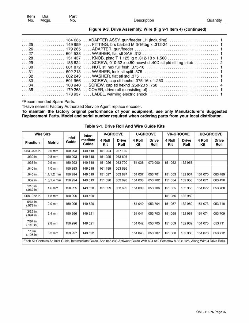
OM-211 076 Page 37
DescriptionPartNo.
Dia.Mkgs.
ItemNo.
Figure 9-3. Drive Assembly, Wire (Fig 9-1 Item 4) (continued)
Quantity
184 685 ADAPTER ASSY, gun/feeder LH (including) 1. . . . . . . . . . . . . . . . . . . . . . . . . . . . . . . . . . . . . . . . . . . . . . . 25 149 959 FITTING, brs barbed M 3/16tbg x .312-24 1. . . . . . . . . . . . . . . . . . . . . . . . . . . . . . . . . . . . . . . . . . . . . . 26 179 265 ADAPTER, gun/feeder 1. . . . . . . . . . . . . . . . . . . . . . . . . . . . . . . . . . . . . . . . . . . . . . . . . . . . . . . . . . . . . . . 27 604 538 WASHER, flat stl SAE .312 1. . . . . . . . . . . . . . . . . . . . . . . . . . . . . . . . . . . . . . . . . . . . . . . . . . . . . . . . . . . 28 151 437 KNOB, plstc T 1.125 lg x .312-18 x 1.500 1. . . . . . . . . . . . . . . . . . . . . . . . . . . . . . . . . . . . . . . . . . . . . . . 29 185 624 SCREW, 010-32 x o.50 hexwhd .40D stl pld slffmg trilob 2. . . . . . . . . . . . . . . . . . . . . . . . . . . . . . . . . . 30 601 872 NUT, stl hex full fnsh .375-16 1. . . . . . . . . . . . . . . . . . . . . . . . . . . . . . . . . . . . . . . . . . . . . . . . . . . . . . . . . 31 602 213 WASHER, lock stl split .375 1. . . . . . . . . . . . . . . . . . . . . . . . . . . . . . . . . . . . . . . . . . . . . . . . . . . . . . . . . . 32 602 243 WASHER, flat stl std .375 1. . . . . . . . . . . . . . . . . . . . . . . . . . . . . . . . . . . . . . . . . . . . . . . . . . . . . . . . . . . . 33 601 966 SCREW, cap stl hexhd .375-16 x 1.250 1. . . . . . . . . . . . . . . . . . . . . . . . . . . . . . . . . . . . . . . . . . . . . . . . 34 108 940 SCREW, cap stl hexhd .250-20 x .750 4. . . . . . . . . . . . . . . . . . . . . . . . . . . . . . . . . . . . . . . . . . . . . . . . . 35 179 263 COVER, drive roll (consisting of) 1. . . . . . . . . . . . . . . . . . . . . . . . . . . . . . . . . . . . . . . . . . . . . . . . . . . . . .
178 937 LABEL, warning electric shock 1. . . . . . . . . . . . . . . . . . . . . . . . . . . . . . . . . . . . . . . . . . . . . . . . . . . . . . . . . . .
*Recommended Spare Parts.�Have nearest Factory Authorized Service Agent replace encoder.To maintain the factory original performance of your equipment, use only Manufacturer’s SuggestedReplacement Parts. Model and serial number required when ordering parts from your local distributor.
Table 9-1. Drive Roll And Wire Guide Kits
Wire SizeInlet Inter- V-GROOVE U-GROOVE VK-GROOVE UC-GROOVE
Fraction MetricInlet
Guide
IntermediateGuide
4 RollKit
DriveRoll
4 RollKit
DriveRoll
4 RollKit
DriveRoll
4 RollKit
DriveRoll
.023-.025 in. 0.6 mm 150 993 149 518 151 024 087 130
.030 in. 0.8 mm 150 993 149 518 151 025 053 695
.035 in. 0.9 mm 150 993 149 518 151 026 053 700 151 036 072 000 151 052 132 958
.040 in. 1.0 mm 150 993 149 518 161 189 053 696
.045 in. 1.1/1.2 mm 150 994 149 519 151 027 053 697 151 037 053 701 151 053 132 957 151 070 083 489
.052 in. 1.3/1.4 mm 150 994 149 519 151 028 053 698 151 038 053 702 151 054 132 956 151 071 083 490
1/16 in.(.062 in.) 1.6 mm 150 995 149 520 151 029 053 699 151 039 053 706 151 055 132 955 151 072 053 708
.068-.072 in. 1.8 mm 150 995 149 520 151 056 132 959
5/64 in.(.079 in.) 2.0 mm 150 995 149 520 151 040 053 704 151 057 132 960 151 073 053 710
3/32 in.(.094 in.) 2.4 mm 150 996 149 521 151 041 053 703 151 058 132 961 151 074 053 709
7/64 in.(.110 in.) 2.8 mm 150 996 149 521 151 042 053 705 151 059 132 962 151 075 053 711
1/8 in.(.125 in.) 3.2 mm 159 997 149 522 151 043 053 707 151 060 132 963 151 076 053 712
Each Kit Contains An Inlet Guide, Intermediate Guide, And 045 233 Antiwear Guide With 604 612 Setscrew 8-32 x .125, Along With 4 Drive Rolls.

Notes

Warranty Questions?
Call1-800-4-A-MILLERfor your localMiller distributor.
miller_warr 1/05
Your distributor also givesyou ...
ServiceYou always get the fast,reliable response youneed. Most replacementparts can be in yourhands in 24 hours.
SupportNeed fast answers to thetough welding questions?Contact your distributor.The expertise of thedistributor and Miller isthere to help you, everystep of the way.
Effective January 1, 2005(Equipment with a serial number preface of “LF” or newer)This limited warranty supersedes all previous Miller warranties and is exclusive with no other
guarantees or warranties expressed or implied.
LIMITED WARRANTY − Subject to the terms and conditionsbelow, Miller Electric Mfg. Co., Appleton, Wisconsin, warrants toits original retail purchaser that new Miller equipment sold afterthe effective date of this limited warranty is free of defects inmaterial and workmanship at the time it is shipped by Miller.THIS WARRANTY IS EXPRESSLY IN LIEU OF ALL OTHERWARRANTIES, EXPRESS OR IMPLIED, INCLUDING THEWARRANTIES OF MERCHANTABILITY AND FITNESS.
Within the warranty periods listed below, Miller will repair orreplace any warranted parts or components that fail due to suchdefects in material or workmanship. Miller must be notified inwriting within thirty (30) days of such defect or failure, at whichtime Miller will provide instructions on the warranty claimprocedures to be followed.
Miller shall honor warranty claims on warranted equipmentlisted below in the event of such a failure within the warrantytime periods. All warranty time periods start on the date that theequipment was delivered to the original retail purchaser, or oneyear after the equipment is sent to a North American distributoror eighteen months after the equipment is sent to anInternational distributor.
1. 5 Years Parts — 3 Years Labor
* Original main power rectifiers* Inverters (input and output rectifiers only)
2. 3 Years — Parts and Labor
* Transformer/Rectifier Power Sources* Plasma Arc Cutting Power Sources* Semi-Automatic and Automatic Wire Feeders* Inverter Power Sources (Unless Otherwise Stated)* Water Coolant Systems (Integrated)* Intellitig* Maxstar 150* Engine Driven Welding Generators
(NOTE: Engines are warranted separately bythe engine manufacturer.)
3. 1 Year — Parts and Labor Unless Specified
* DS-2 Wire Feeder* Motor Driven Guns (w/exception of Spoolmate
Spoolguns)* Process Controllers* Positioners and Controllers* Automatic Motion Devices* RFCS Foot Controls* Induction Heating Power Sources and Coolers* Water Coolant Systems (Non-Integrated)* Flowgauge and Flowmeter Regulators (No Labor)* HF Units* Grids* Maxstar 85, 140* Spot Welders* Load Banks* Arc Stud Power Sources & Arc Stud Guns* Racks* Running Gear/Trailers* Plasma Cutting Torches (except APT & SAF
Models)* Field Options
(NOTE: Field options are covered under TrueBlue® for the remaining warranty period of theproduct they are installed in, or for a minimum ofone year — whichever is greater.)
4. 6 Months — Batteries
5. 90 Days — Parts
* MIG Guns/TIG Torches
* Induction Heating Coils and Blankets
* APT & SAF Model Plasma Cutting Torches
* Remote Controls
* Accessory Kits
* Replacement Parts (No labor)
* Spoolmate Spoolguns
* Canvas Covers
Miller’s True Blue® Limited Warranty shall not apply to:
1. Consumable components; such as contact tips,cutting nozzles, contactors, brushes, slip rings,relays or parts that fail due to normal wear. (Exception:brushes, slip rings, and relays are covered on Bobcat,Trailblazer, and Legend models.)
2. Items furnished by Miller, but manufactured by others,such as engines or trade accessories. These items arecovered by the manufacturer’s warranty, if any.
3. Equipment that has been modified by any party other thanMiller, or equipment that has been improperly installed,improperly operated or misused based upon industrystandards, or equipment which has not had reasonableand necessary maintenance, or equipment which hasbeen used for operation outside of the specifications for theequipment.
MILLER PRODUCTS ARE INTENDED FOR PURCHASE ANDUSE BY COMMERCIAL/INDUSTRIAL USERS ANDPERSONS TRAINED AND EXPERIENCED IN THE USE ANDMAINTENANCE OF WELDING EQUIPMENT.
In the event of a warranty claim covered by this warranty, theexclusive remedies shall be, at Miller’s option: (1) repair; or (2)replacement; or, where authorized in writing by Miller inappropriate cases, (3) the reasonable cost of repair orreplacement at an authorized Miller service station; or (4)payment of or credit for the purchase price (less reasonabledepreciation based upon actual use) upon return of the goods atcustomer’s risk and expense. Miller’s option of repair orreplacement will be F.O.B., Factory at Appleton, Wisconsin, orF.O.B. at a Miller authorized service facility as determined byMiller. Therefore no compensation or reimbursement fortransportation costs of any kind will be allowed.
TO THE EXTENT PERMITTED BY LAW, THE REMEDIESPROVIDED HEREIN ARE THE SOLE AND EXCLUSIVEREMEDIES. IN NO EVENT SHALL MILLER BE LIABLE FORDIRECT, INDIRECT, SPECIAL, INCIDENTAL ORCONSEQUENTIAL DAMAGES (INCLUDING LOSS OFPROFIT), WHETHER BASED ON CONTRACT, TORT ORANY OTHER LEGAL THEORY.
ANY EXPRESS WARRANTY NOT PROVIDED HEREIN ANDANY IMPLIED WARRANTY, GUARANTY ORREPRESENTATION AS TO PERFORMANCE, AND ANYREMEDY FOR BREACH OF CONTRACT TORT OR ANYOTHER LEGAL THEORY WHICH, BUT FOR THISPROVISION, MIGHT ARISE BY IMPLICATION, OPERATIONOF LAW, CUSTOM OF TRADE OR COURSE OF DEALING,INCLUDING ANY IMPLIED WARRANTY OFMERCHANTABILITY OR FITNESS FOR PARTICULARPURPOSE, WITH RESPECT TO ANY AND ALL EQUIPMENTFURNISHED BY MILLER IS EXCLUDED AND DISCLAIMEDBY MILLER.
Some states in the U.S.A. do not allow limitations of how long animplied warranty lasts, or the exclusion of incidental, indirect,special or consequential damages, so the above limitation orexclusion may not apply to you. This warranty provides specificlegal rights, and other rights may be available, but may varyfrom state to state.
In Canada, legislation in some provinces provides for certainadditional warranties or remedies other than as stated herein,and to the extent that they may not be waived, the limitationsand exclusions set out above may not apply. This LimitedWarranty provides specific legal rights, and other rights may beavailable, but may vary from province to province.

PRINTED IN USA © 2005 Miller Electric Mfg. Co. 1/05
Miller Electric Mfg. Co.An Illinois Tool Works Company1635 West Spencer StreetAppleton, WI 54914 USA
International Headquarters−USAUSA Phone: 920-735-4505 Auto-AttendedUSA & Canada FAX: 920-735-4134International FAX: 920-735-4125
European Headquarters −United KingdomPhone: 44 (0) 1204-593493FAX: 44 (0) 1204-598066
www.MillerWelds.com
Model Name Serial/Style Number
Purchase Date (Date which equipment was delivered to original customer.)
Distributor
Address
City
State Zip
Please complete and retain with your personal records.
Always provide Model Name and Serial/Style Number.
Contact a DISTRIBUTOR or SERVICE AGENCY near you.
Welding Supplies and Consumables
Options and Accessories
Personal Safety Equipment
Service and Repair
Replacement Parts
Training (Schools, Videos, Books)
Technical Manuals (Servicing Informationand Parts)
Circuit Diagrams
Welding Process Handbooks
Contact the Delivering Carrier to:
For Service
Owner’s Record
File a claim for loss or damage duringshipment.
For assistance in filing or settling claims, contactyour distributor and/or equipment manufacturer’sTransportation Department.
Contact your Distributor for:
To locate a Distributor or Service Agency visitwww.millerwelds.com or call 1-800-4-A-Miller