winnie lu - autonomous vehicle and risk assessment
TRANSCRIPT

AUTONOMOUS VEHICLE AND RISK ASSESSMENT
Winnie Lu | Division of Risk Management and Societal Safety LTH | Lund University

1
AutonomousVehicleandRiskAssessment
WinnieLu
Lund2021

2
Autonomous Vehicle and Risk Assessment Winnie Lu Number of pages: 71 Illustrations made by the author: 37 Keywords: Driverless, automated, crafts, safety, security, risk identification, risk analysis, risk evaluation, risk management Abstract Accidents with vehicles happen more often than they should, whether it is by road traffic accidents or maritime accidents out in the sea. One big contributing factor is human error. Distraction, influence of alcohol/drugs, carelessness and speeding are examples of factors that can lead to severe injuries for the passengers, the surrounding people and to infrastructure. By transferring human maneuvers to a more autonomous operation, it is believed that safety will increase. This is true for all vehicle types, such as cars, ships, drones and trains – which are the vehicles the thesis is focusing on. Autonomous vehicles are developing fast, and it is also the case of their risk assessment methods. Research in this field is new and a general applicable method that works on most systems and situations does not exist. Not even the industries have a clear image of how risk assessment should be done on such vehicles. At the same time, new security risk emerges. When a technology becomes less human reliant and have fewer manual functions, malicious attackers find new areas to strike. The risk assessment method must thus cover both safety and security perspectives. The thesis’ aim is to increase knowledge about risk assessment of autonomous vehicle and to analyze the found information in order to assemble a holistic risk assessment framework. A Scoping Study and consultative interviews were conducted to investigate the current knowledge about assessment methods and the results formed the RAAV framework. The RAAV framework is based on a customized S&S model.
© Copyright: Division of Risk Management and Societal Safety, Faculty of Engineering Lund University, Lund 2021 Avdelningen för Riskhantering och samhällssäkerhet, Lunds tekniska högskola, Lunds universitet, Lund 2021.
Division of Risk Management and Societal Safety Faculty of Engineering
Lund University P.O. Box 118
SE-221 00 Lund Sweden
http://www.risk.lth.se
Telephone: +46 46 222 73 60
Riskhantering och samhällssäkerhet Lunds tekniska högskola
Lunds universitet Box 118
221 00 Lund
http://www.risk.lth.se
Telefon: 046 - 222 73 60

3
Acknowledgement A big thanks to my supervisor Henrik Tehler for all the support and insightful comments. Your patience and your understanding of a student’s problems, such as being last-minute, without any signs of judgment but with lots of encouragement, have really made the process much easier for me. Gratitude should also be directed to Christian Martinsson and Jan Espen Presteng for helping with finding interviewees and assisting in other aspects, as well as to the interviewees that took time out of their schedule to enrich the thesis with their expertise. Lastly, I want to thank my family and friends for their endless support throughout my years in university. To my husband who has endured all of my worries and constantly brightens my day in silly ways; to my parents and siblings who invite me over for home-cooked dinners after exams; to my study buddy who takes turns with me to vent about school while studying long hours; to my cats for being furry balls of cuteness; to all my other friends and family who cheered me on in so many different ways – thank you so much. I am infinitely grateful for you all.

4
Table of Contents Acknowledgement ......................................................................................................... 3
Table of Contents .......................................................................................................... 4
List of Illustrations ........................................................................................................ 5
List of Tables .................................................................................................................. 6
List of Acronyms ........................................................................................................... 7
1 Introduction ................................................................................................................. 9
1.1 Rationale and Research Aim .......................................................................................... 9
1.2 Research Questions and Objectives ........................................................................... 10
1.3 Thesis Structure .............................................................................................................. 11
2 Background ............................................................................................................... 13
2.1 Current Status of Autonomous Vehicles .................................................................... 13
2.2 Risk Management ........................................................................................................... 14
2.3 Delimitation ...................................................................................................................... 16
3 Methodology ............................................................................................................. 17
3.1 Scoping Study ................................................................................................................. 17 3.1.1 Step 1: Identifying the Research Question ............................................................................ 17 3.1.2 Step 2: Identifying Relevant Articles ....................................................................................... 17 3.1.3 Step 3: Study Selection .............................................................................................................. 18 3.1.4 Step 4: Analysis ............................................................................................................................ 19 3.1.5 Limitations of Scoping Study .................................................................................................... 19
3.2 Consultative Interviews ................................................................................................. 20 3.2.1 Limitations of Consultative Interviews ................................................................................... 20
3.3 Framework Compilation ................................................................................................ 20
4 Scoping Study Results ............................................................................................ 21
4.1 Overall Analysis .............................................................................................................. 21 4.1.1 Vehicle Types ................................................................................................................................ 22 4.1.2 Risk Assessment Steps .............................................................................................................. 25 4.1.3 Risk Types ...................................................................................................................................... 26 4.1.4 Group 2 Subject in Focus ........................................................................................................... 27
4.2 In-Depth Analysis ............................................................................................................ 28 4.2.1 Context and System Description .............................................................................................. 29 4.2.2 Security Risk Methods ................................................................................................................ 32 4.2.3 Accident Risk Methods ............................................................................................................... 36 4.2.4 Combined Method ........................................................................................................................ 43 4.2.5 Identified Risks ............................................................................................................................. 44
5 Consultative Interviews Results ............................................................................ 47
5.1 Standards and Methods Used ...................................................................................... 47

5
5.2 The Risk Management Process .................................................................................... 48
6 Framework Compilation .......................................................................................... 49
6.2 Customized S&S ............................................................................................................. 49
6.3 The RAAV Framework .................................................................................................... 50
6.4 Benefits with the RAAV Framework ............................................................................. 52
6.5 Limitations with the RAAV Framework ....................................................................... 53
6.6 Recommendations for Future Development .............................................................. 54
7 Summary/Conclusion .............................................................................................. 55
7.1 Summary of Findings ..................................................................................................... 55
7.2 Conclusion ....................................................................................................................... 55
References ................................................................................................................... 57
Appendices .................................................................................................................. 62
A1 Standards ......................................................................................................................... 62
A2 System Models ................................................................................................................ 63
A3 Identified Attacks ............................................................................................................ 65
A4 Example of Using the RAAV Framework ..................................................................... 67
List of Illustrations Figure 1: Five eras of safety ............................................................................................. 10
Figure 2: Risk management process ................................................................................. 16
Figure 3: Scoping Study process ...................................................................................... 19
Figure 4: Publication year ................................................................................................. 21
Figure 5: Source type ....................................................................................................... 22
Figure 6: Vehicle type ...................................................................................................... 23
Figure 7: Driving automation levels ................................................................................... 24
Figure 8: Risk assessment steps covered ......................................................................... 26
Figure 9: Type of risk ....................................................................................................... 26
Figure 10: Subjects .......................................................................................................... 28
Figure 11: Risk models and frameworks ........................................................................... 28
Figure 12: Attack tree analysis ......................................................................................... 33
Figure 13: Automotive security taxonomy ......................................................................... 35
Figure 14: Bayesian defense graph .................................................................................. 36

6
Figure 15: STPA .............................................................................................................. 37
Figure 16: STECA ............................................................................................................ 38
Figure 17: Fault tree analysis ........................................................................................... 39
Figure 18: Funtional safety methodology .......................................................................... 40
Figure 19: Performance level required .............................................................................. 41
Figure 20: Bayesian network ............................................................................................ 41
Figure 21: Bayesian network probability ............................................................................ 42
Figure 22: S&S ................................................................................................................ 44
Figure 23: Malicious incident components ......................................................................... 45
Figure 24: Costumized S&S ............................................................................................. 50
Figure A1: System Model of Autonomous Car ................................................................... 63
Figure A2: Another System Model of Autonomous Car ...................................................... 64
Figure A3: System Model of Autonomous Ship ................................................................. 64
Figure A4: Framework Example Step 1 ............................................................................. 67
Figure A5: Framework Example Step 2 ............................................................................. 67
Figure A6: Framework Example Step 3 ............................................................................. 68
Figure A7: Framework Example Step 4 ............................................................................. 68
Figure A8: Framework Example Step 5 ............................................................................. 69
Figure A9: Framework Example Step 6 ............................................................................. 69
Figure A10: Framework Example Step 7 ........................................................................... 70
Figure A11: Framework Example Step 8 ........................................................................... 70
Figure A12: Framework Example Step 9 ........................................................................... 71
Figure A13: Framework Example Step 10 ......................................................................... 71
List of Tables Table 1: Autonomous component/function ........................................................................ 30
Table 2: Hazard sources .................................................................................................. 43
Table A1: Standards ........................................................................................................ 60
Table A2: Identified attacks .............................................................................................. 63

7
List of Acronyms AI Artificial Intelligence AM Amplitude Modulation ATA Attack Tree Analysis AUV Autonomous Underwater Vehicle BN Bayesian Network CCA Cause-Consequence Analysis CD Compact Disc ConOps Concept of Operations CPS Cyber-Physical System CVSS Common Vulnerability Scoring System CWE Common Weakness Enumeration DAB Digital Audio Broadcasting Def Stan UK Ministry of Defense’s Defense Standard DoS Disk Operating System DTDM Dynamic Tactical Decision Making ETA Event Tree Analysis FM Frequency Modulation FMEA Failure Mode and Effects Analysis FTA Fault Tree Analysis GNSS Global Navigation Satellite System GPS Global Positioning System H SystSäk Swedish Armed Forces’ Materiel Administration handbook of System Safety HARA Hazard Identification and Risk Assessment HazId Hazard Identification HazOp Hazard and Operability Study HCP Human-Cyber-Physical system IEC International Electrotechnical Commission IMO International Maritime Organization IoT Internet of Things ISO International Organization for Standardization LiDAR Light Detection and Ranging MiTM Man-In-The-Middle Attack NHTSA The National Highway Traffic Safety Administration OBD On-Board Diagnostics PACT Pilot Authorization and Control of Tasks PLr Performance Level Required RAAV Risk Assessment for Autonomous Vehicle RO Research Objective ROV Remotely Operated Underwater Vehicle RQ Research Question S&S Safety and Security Integration Method SAE Society of Automotive

8
SIL Safety Integrity Level SRA Society for Risk Analysis SSC Shore-Based Control Center STECA System Theoretic Early Concept Analysis STPA Systems-Theoretic Process Analysis
STRIDE Spoofing, Tampering, Repudiation, Information disclosure, Denial of service, Elevation of privileges
UAV Unmanned Aerial Vehicle UCA Unsafe Control Action USB Universal Serial Bus UTO Unattended Train Operation V2I Vehicle-to-Infrastructure V2V Vehicle-to-Vehicle V2X Vehicle-to-Everything

9
1 Introduction In this introductory chapter, the purpose behind the thesis and the overall approach are described. The rationale and research aim are presented first, followed by the research questions and objectives, and the chapter concludes with the thesis structure.
1.1 Rationale and Research Aim Every 23 seconds, one person dies from road traffic according to WHO (WHO, 2018). It is not only car users among these lost lives, but also cyclists, motorcyclists and pedestrians. One huge contribution to the 1.3 million road traffic deaths per year is human error. Factors such as speeding, alcohol influence, influence of other psychoactive substances, distracted driving and carelessness lead to unsafe road conditions. (WHO, 2021)
Accidents in the marine are fortunately not as vast as for the road, but still significant. In 2019, 3062 causalities and incidents were reported to the European Marine Casualty Information Platform. 54 percent of the contributing factors are due to human action. (EMSA, 2020).
Human influence on any traffic can thus be seen as a safety issue. Technology has for that reason developed features that assist the human driver with maneuvering, monitoring and even operating the vehicle. The US National Highway Traffic Safety Administration (NHTSA) defines five eras of safety (NHTSA, n.d.), as seen in Figure 1, and we are now in the era of Partially Automated Safety Features. Next phase would be going into full automation. This is true for self-driving cars, but also for other vehicle types. For instance, research in autonomous ship has increased significantly in the last few years (de Vos, Hekkenberga, & Valdez Banda, 2021), autonomous trucks are on their way (Fortos, 2017) and autonomous drones are becoming increasingly popular (Allouch, Koubâa, Khalgui, & Abbes, 2019). In conclusion, all types of vehicle are moving towards autonomous operations.
The benefits of autonomous vehicles are many. It can reduce lost lives, reduce pollution by i.e. more efficient route planning, create more time for humans to do other practices during commuting (Wang, Zhang, Huang, & Zhao, 2020), reducing human operation costs in i.e. ship crew (Tam & Jones, 2018), accessing areas too dangerous for humans with i.e. autonomous mining vehicles (Mining Technology, 2021), enhance transportation of goods with i.e. drone transportation (Allouch, Koubâa, Khalgui, & Abbes, 2019), among others. Autonomy is not a new concept but implementing the concept in vehicles forms new unpredictable hazards. It is important that the risks will be identified, analyzed and then evaluated. It is especially true for a new technology that might have a huge impact on the future transportation.
Autonomous vehicles are safety-critical systems, errors in the system can lead to fatal consequences. The vehicle must be considered sufficiently safe before it can be commercially or privately used. The contemporary research in that field is still struggling. For instance, there are still uncertainty issues when it comes to machine learning for artificial intelligence, which role is to identify patterns and make decisions (Shafaei, Kugele, Osman, & Knoll, 2018). The vehicle must also be prepared for all traffic scenarios – and there are many – which is a struggle for the testing phase (Wagner, Groh, Kühbeck, Dörfel, & Knoll, 2018). Moreover, going fully

10
autonomous opens up another aspect for malicious attackers. Cyber risk, sensors being jammed and hijacking the critical vehicular communication system, among others, are now an emerging security issue (Tam & Jones, 2018; Bouchelaghem, Bouabdallah, & Omar, 2021). Ensuring both safety and security are consequently a priority. How risk is assessed is an interesting and crucial part of the manufacturing and development phase of these self-operating vehicles.
The technology of autonomous vehicles is developing rapidly and the end goal might be in the close future. To stay up to date on the risk assessment development process which evolves side-by-side the vehicle can be troublesome, when new information emerges all the time. Currently, there exist no comprehensive overview of how risk should be dealt with autonomous vehicles, only scattered contributions from different researchers. To process all new incoming research and summarize it to something concrete can also pose as a challenge. This thesis will try to tackle this problem.
The research aim of the thesis is twofold. The first aim is to is to increase knowledge about how risks are assessed during the design and manufacturing phase of autonomous vehicle production. The second aim is to analyze the gathered knowledge and to assemble a risk assessment framework regarding autonomous vehicles that utilizes the compiled information but in a more holistic manner. The framework can be used as a starting point when assessing risk in autonomous vehicle and are in line with modern risk science.
Figure 1: The five eras of safety, figure adapted from NHTSA (n.d.).
1.2 Research Questions and Objectives The aim is met through three parts. First, a literary study is performed in order to find out the current research development, then exploring how industries are working with this subject by conducting consultative interviews, and lastly, compiling a framework of the discovered facts. The research questions and objectives to meet the aim are presented below.

11
Research Questions (RQ):
1. What is known in current literature and studies about risk assessment methods for autonomous vehicles during design and manufacturing phase and the context in which such methods are applied?
2. How do companies work with risk management regarding autonomous vehicles today?
3. How should the risk of autonomous vehicle be assessed during design and manufacturing phase based on modern risk science and current approaches?
Research Objectives (RO):
1. To investigate the current literature about risks and autonomous vehicles during design and manufacturing phase.
2. To conduct consultative interview with practitioners working with risk and autonomous vehicles.
3. To create a framework that may be used in the industry.
A Scoping Study method is conducted as the literary study, where RQ1 is answered. Next, the interviews give an insight to RQ2. These will then assist in answering RQ3 in the framework compilation part. Each research objective is formulated for each of the three respective steps in the thesis.
1.3 Thesis Structure The structure of the thesis is as follows:
• Chapter 2: Background
o Presents the current status of autonomous vehicles. The chapter also introduces the concept of risk management. Finally, it ends with the thesis’ delimitations.
• Chapter 3: Methodology
o Describes the methodology for the scoping study, the consultative interviews and the framework compilation.
• Chapter 4: Scoping Study Results
o The findings from the Scoping Study are presented as an overall analysis and an in-depth analysis.
• Chapter 5: Consultative Interviews Results
o The findings from the consultative interviews are presented.
• Chapter 6: Framework Compilation
o The framework is presented.

12
• Chapter 7: Discussion/conclusion
o Summarizes and discusses key findings.

13
2 Background This section provides a background on autonomous vehicles, risk management and the delimitations of the thesis.
2.1 Current Status of Autonomous Vehicles First of all, it is good to distinguish the word automated and autonomous, as they are oftentimes used interchangeably. Automated vehicles are vehicles which can monitor the environment and can operate by themselves most of the time but will need a human operator to regain control in certain situations. Autonomous vehicles, however, do not require any human interaction at all and could thus be considered as a higher level of automation. (Bouchelaghem, Bouabdallah, & Omar, 2021) There exist several classifications of the level of autonomy, i.e. by Society of Automotive Engineers (SAE) International (SAE, 2018), U.S. national Highway Traffic Safety Association (NHTSA, 2016) and Pilot Authorization and Control of Tasks (PACT) framework (Bonner, Taylor, Fletcher, & Miller, 2000). The classifications are constructed based on one specific type of vehicle, but the general concept of the automation levels can be applied to any vehicle.
On the topic of vehicle types, the Merriam-Webster Dictionary’s definition of a vehicle is “a means of carrying or transporting something (planes, trains, and other vehicles)” (Merriam-Webster, n.d.). Vehicle is thus not limited to motor vehicles like cars, but also other crafts such as aircrafts, spacecrafts, railed vehicles and watercrafts. All these vehicle types are included in the thesis but the main focus is on autonomous cars, ships and drones. This is due to the fact that these vehicle types were most commonly mentioned in the literary study.
Automated vehicles already exist in the open traffic to some degree. In the aviation industry, the autopilot function makes the operations highly automated, letting the human pilot have more time and freedom to oversee the overall status of the flight instead. The autopilot can read the environment, such as finding the current navigation position, and have actuators controlling the movement. (FAA, 2009) Manned automated flights are thus common, full autonomous operations are however not established yet (Johnsen & Evjemo, 2017). Automated functions in modern cars have also become more and more common. Cars nowadays are equipped with driving assistance such as lane keeping and cruise control (Maple, Bradbury, Le, & Ghirardello, 2019). Fully autonomous cars are in development right now, companies like Tesla (Tesla, n.d.), Google (Waymo, n.d.) and Volvo (Volvo, 2020) are in the leading edge of that field (Chakraborty, 2021), but not yet entirely ready. Autonomous vehicles are in other words up-and-coming and will probably be released in the near-future.
Safety and security issues are contributing factors that hinders the development process of autonomous vehicles (Wang, Zhang, Huang, & Zhao, 2020). Safety deals with accidental risk that arises from the system. Safety issues affect the environment, the system itself and humans. To create a safe system is done by reducing the risk of harm to an acceptable level. Security, on the other hand, is about antagonistic attacks and malicious risk. The attacks on the system are usually oriented from the environment, i.e. by an attacker. In order to become more secure, the risk related to confidentiality, integrity and availability must minimize. Safety and security

14
are of course interrelated with commonalities but also differences and are crucial for the development process of the vehicles. (Amro, Kavallieratos, Louzis, & Thieme, 2020)
There are standards that regulate the safety and security requirements. Some standards are broad and covers everything which is considered as a machine, which autonomous vehicles are, some standards are especially developed to a certain vehicle type, i.e. cars. The contents in the standards also vary from functional safety to cyber security. In Appendix A1, some standards regarding safety and/or security relevant to autonomous vehicles are presented.
2.2 Risk Management The science of risk management has evolved over the years. Traditionally, the performance of risk analysis is based on probabilities, and those probabilities were acquired through historic data and were the main source for deciding a risk level. This was especially true for the nuclear plant industry and the traditional perspective has proven to be quite successful for the majority of the time. However, when a set of worst case scenarios occur simultaneously, severe accidents have taken place. In complex environments, with many systems tightly coupled, disasters have found ways to creep in. Realizing that the traditional way of managing risk was not enough, a new perspective has evolved. This new outlook is characterized by uncertainty rather than probability, the definition of risk has broadened and the focus is not only on what should be done to prevent risk, but also on how the operations are managed now. (Aven, 2018; Tehler, 2020)
There are many varieties of definition of risk. The new risk perspective’s definitions normally accentuate uncertainty and the severity of events or consequences. Probability, on the other hand, is only one way of describing and quantizing uncertainty. Uncertainty is a situation where true or false are unknown, in other words is that it is unknown if an event could possibly affect harm or not. It also covers the unknown consequences and unknown severity. (Aven, 2018; Tehler, 2020) With the modern risk perspective, risk scientists have found a distinction between fundamental risk analysis and applied risk analysis. The fundamental can be considered as the general type of analysis, where the practices are generic and are not bound to any subject or situation. Conversely, applied risk is like having one foot in risk science and the other in another science field and then combining them. Even though there is a distinction between the two analysis fields, they have strong interaction with each other. The fundamental risk analysis should assist in creating an applied analysis, and the applied analysis should provide with new insights to develop the fundamental one. (Aven & Flage, 2020)
Two organizations that have high influence on risk management are the International Organization for Standardization (ISO) and Society for Risk Analysis (SRA). ISO develops and publishes worldwide technical, industrial and commercial standards, including risk management standards (ISO, n.d.). SRA is a learned society for anyone interested in risk analysis, where information and methodologies about risk are discussed, risk knowledge are being promoted and collaborations about risk management between organizations are encouraged (SRA, 2021).

15
ISO defines risk management process as Figure 2. Risk assessment is a part of the whole management and consist of three main steps; Risk Identification, Risk Analysis and Risk Evaluation. These are to be performed iteratively and systematically. (ISO, 2018)
The aim of risk identification is to recognize hazards or undesired events that could hinder the achievement of goals, in order to be able to further perform an analysis. Important to remember during this step is to include all types of hazards, even seemingly insignificant ones, as it may be difficult to determine the triggered consequences. (Coppola, 2011) Additionally, before starting this step, the scope of the risk management activities should be decided, the context of the system described and the criteria of what type of risks and the amount of what the system can take should be specified. (ISO, 2018)
In the step of risk analysis, the purpose is to characterize risk. The characterization should consider risk sources, consequences, scenarios, uncertainties, complexity, connectivity, and if possible, likeliness. It is possible to conduct a solely qualitative analysis, or quantitative, but could also be combined. (ISO, 2018) Conducting quantitatively usually expresses the risk as a probability distribution, while qualitatively uses other types of qualitative measures, such as characterizing risk into classes without using likelihoods or frequencies (Aven & Renn, 2010).
The last step of the risk assessment, as per the ISO-standard, is risk evaluation. The evaluation is performed in accordance with an established risk criteria and can lead to decisions such as doing nothing further, treating risks or to reconsider objectives (ISO, 2018). Evaluation is the last step before treating the risk, which concludes the risk management process.
Risk management is a time-consuming and extensive process. Not all new technologies have been able to form an elaborate methodology for each step, which gives an insight to the readiness of the product. The three risk assessment steps could be used as a landmark of how far a technology has developed.

16
Figure 2: Risk management process by ISO, figure adapted from ISO (2018).
2.3 Delimitation Autonomous vehicle have the possibilities of becoming a life changing technology that might form new living conditions in the future. With that comes risks. Risks with autonomous vehicle can stretch from the initial design phase to the testing phase, then the usage phase and even the decay phase. Delimitations of risks that will be included in the thesis must be drawn. Only risk that belongs to and arises from the manufacturing and design phase of autonomous vehicles is considered. Risk about pollution due to a potential higher number of vehicles in use, job loss for chauffeurs and pilots, laws and policies, economics and the creation of connected and smart cities, which are all factors to be considered in the testing and usage phase, are beyond the scope of the thesis.

17
3 Methodology This chapter explains the methodology behind the scoping study, consultative interviews and the construction of the framework.
3.1 Scoping Study Scoping study is a method for reviewing literature. It is especially adapted to search broad topics to address what kind of papers and studies that exist within the subject. At the same time, it is a tool for identifying research gaps in existing literatures. The aim of conducting such a study is to gain a full systematic review on the topic. (Arksey & O'Malley, 2005) Arksey and O’Malley (2005) presents a scoping study framework consisting of six steps. This thesis will utilize the first four steps, which are described in the following subsections.
3.1.1 Step 1: Identifying the Research Question The first step is to set a research question for the scoping study. It should be broad to not exclude any useful information. (Arksey & O'Malley, 2005) The question the thesis research is as follows:
What is known from scientific literature about risk assessment regarding autonomous vehicles?
It is important to clarify any ambiguous terms in the question (Arksey & O'Malley, 2005). Risk assessment and vehicles may come across as ambiguous. The definitions of these terms are described in chapter 2 Background.
3.1.2 Step 2: Identifying Relevant Articles The purpose of this step is to identify articles that are relevant to the research question. This could be done in two parts; database selection and search query identification (Beerens & Tehler, 2016).
Database Selection There are different sources to gather material, the most feasible for this thesis is using electronic databases. Scopus, owned by Elsevier, is the sole database for the article search in the thesis because of its wide range of research fields (Beerens & Tehler, 2016). No grey literature was explored due to the suspicion of companies’ non-willingness to publish well detailed publications about their up-and-coming driverless vehicles.
Search Query Identification In order to perform an efficient search, a search string could be convenient. The search string was based on a Boolean approach and included keywords and their synonyms (Beerens & Tehler, 2016). Three main keywords were determined; “Autonomous”, “Vehicle” and “Risk”. Together with their synonyms, the search string consisted of:

18
1. Autonomous OR Self-Driving OR Driverless;
2. Vehicle OR Transport OR Craft;
3. Risk OR Safety OR Danger OR Hazard.
The three keywords and their synonyms were strung together with an AND operator. Initially, there was a lot of different synonyms for “Vehicle”, such as automobile, ship, train and so on. But after making a search with only the three words in the list above, it was found that it generated a huge number of findings that also covered other vehicle types other than cars. Satisfied with this result, all other synonyms were neglected.
It should also be pointed out that “safety” might not be considered as a synonym of “risk”, as the word “risk” usually has a negative connotation. These words were paired anyway due to the reason that they both could relate to risk assessment practices.
3.1.3 Step 3: Study Selection With the search query identification, a total of 10087 documents results was found. Not all documents were in English nor met the requirements of being peer reviewed, which is the initial criteria. By being peer reviewed, the article can be considered as more scientifically valid and is ensured to hold a higher standard (Moberg, 2015).
Initial Criteria:
• Peer reviewed;
• English.
Duplicates, according to their title, were removed with the help of Microsoft Excel. Thereafter, the title analysis could begin. To conduct the analysis, an inclusion and exclusion criteria were formed and are presented below. The same criteria formed the basis of the next step, which is the abstract analysis. Some documents were unable to open or obtain. The general steps and findings are illustrated in Figure 3.
Inclusion Criteria:
• Article focuses on autonomous vehicle(s);
• Article addresses aspect(s) of risk assessment or identified risks.
Exclusion Criteria:
• Article emphasizes on risk outside the design and manufacturing phase of autonomous vehicles, such as pedestrian movement, hazardous road routes or environmental impacts;
• Article emphasizes on legislations or policies.
After the abstract analysis, 41 documents fit the scoping study’s research question. These were categorized into two groups, group 1 and 2. Group 1 consists of articles that present any type

19
of risk assessment model or presents identified risks that have a holistic view, whilst group 2 has articles that present risk assessment with specific functions or areas within autonomous vehicles and are too detailed to be read as thoroughly as group 1, but still give insight to the overall research field in the subject.
Figure 3: The Scoping Study process.
3.1.4 Step 4: Analysis The analysis is performed in two separate steps; an overall analysis and an in-depth analysis. The overall analysis presents diagrams of interesting facts such as the articles publication year, what type of vehicle they relate to, the risk assessment steps covered and more. It gives the reader an overall insight of the findings from the articles. The in-depth analysis presents details of risk assessment method steps and some identified risks.
3.1.5 Limitations of Scoping Study There are certain limitations when conducting a scoping study. Human factor is one of great importance. Which articles that are considered as relevant are based on the inclusion and exclusion criteria written in 3.1.3 Step 3: Study Selection, yet due to the human factor, it is

20
possible to miss relevant articles – especially when there are over two thousand titles to go over. To combat this, the titles were checked twice and if a title was on the borderline of being included or not, it would always pass forward to the next analysis phase just in case.
To filter documents based on their title is essential, it would otherwise be very time consuming. Relevant articles may however get filtered out due to non-explanatory titles. Because of this fact, short titles that includes at least one inclusion criteria, and none of the exclusion criteria, got passed to the abstract analysis.
Charting the articles by their abstracts has shown to be challenging, a few were hard to be defined into one group. Some adjustments and re-categorization had to be made after a thorough read-through of the articles.
In the analysis step, some articles did not explain interesting details thoroughly and seem to assume that the reader already has that knowledge. In those cases, external sources had to be brought in. Thus, the scoping study results include some sources beyond the articles found from the search in Elsevier.
3.2 Consultative Interviews Two interviews were carried out. The interviewees were selected through personal connections. One of the interviews was held through a phone call and was semi-structured. The other interview was conducted as a written questionnaire, which the interviewee could elaborate the answers further upon request. The interviews serve as an insight on how industries are assessing risk on autonomous vehicles.
3.2.1 Limitations of Consultative Interviews As the thesis was written during summer vacation period, it has been difficult to book interviews. Several requests have been sent out but few replies have been received. The number of interviews for the thesis is thus limited. This has led to more emphasis being placed on the Scoping Study for the Framework Construction, whilst the interviews supports certain segments. The interviews held are still answering RQ2 and achieve RO2, but to a slightly lesser extent than initially desired.
3.3 Framework Compilation The results from the Scoping Study and the Consultative Interviews were compared and analyzed. The creation of the framework took inspiration of the results and the goal of the framework is to be as comprehensive as possible.

21
4 Scoping Study Results This chapter presents the results from the Scoping Study. The subchapter Overall Analysis examines articles from both Group 1 and 2, whereas the subchapter In-Depth Analysis dive into risk assessment methods and identified risk found in Group 1 articles.
4.1 Overall Analysis The findings from the Scoping Study resulted in 41 articles, of which 16 are from Group 1 and 25 articles from Group 2. Figure 4 shows the publication year of the articles. When performing the search, no limitations of publication year was set. Even though, all of them are published at present time, from 2016 and forward – showing that risk assessment for autonomous vehicles is a relatively new field. The peak of the publication year is in the last two years and we can expect that 2021 and the years ahead will continue to explore this area.
Figure 4: The publication year for articles from Group 1 and Group 2.
Beyond the 41 found articles, other sources from other articles, documents and websites have been added to the Scoping Study results. These are called external sources, as seen in Figure 5. The purpose of the external sources is to cover or reenforce the Scoping Study articles with information they are considered lacking for the In-Depth Analysis and as a way to compensate for the limited number of interviews. Some of the external sources were found through the references of group 1 and 2 or through searching more information about a subject if it is considered lacking in the original article.
0
2
4
6
8
10
12
14
2016 2017 2018 2019 2020 2021
Publication Year
Group 1 Group 2

22
Figure 5: The three source types.
The overall analysis continues in the next subsections covering vehicle types addressed in the Scoping Study articles, the risk analysis steps, risk types and which subject the articles from Group 2 focuses on. 4.1.1 Vehicle Types There were only four vehicle types that were brought up in the articles, the majority was cars. The word vehicle is often loosely translated to automobile, which could be one of the reasons behind it. Although, the search string also included “craft” and “transport”. When filtering the articles, there seem to be a larger proportion of other vehicle types than cars compared to the final findings, but not many got passed through the filtering due to their lack of focus on the risk assessment process.
Autonomous cars could also be more popular, as they are more likely to be used in the private sector than the other vehicle types. It does not necessarily mean that autonomous cars have come further in the development process, just that they are a more interesting research topic.
The four mentioned types of vehicles were cars, vessels, unmanned aerial vehicles and trains. How many of which are illustrated in Figure 6.
16
25
9
Source Type
Group 1 Group 2 External

23
Figure 6: The four vehicle types found in Group 1 and Group 2.
Autonomous Cars Some degree of automation in cars are already in the open road, such as cars with electronic driver assistance system, advanced emergency braking system, adaptive cruise control and automatic parking (Ivanov & Shadrin, 2018). Fully autonomous cars are however not quite there yet, although they are emerging (Maple, Bradbury, Le, & Ghirardello, 2019). There are several ways of classifying driving automation, however, the most common definition comes from SAE. SAE International is a global association in the aerospace, automotive and commercial-vehicle industries and classifies the driving automation in five levels, as seen in Figure 7 (SAE, 2021).
0
5
10
15
20
25
Cars Vessels UAVs Trains
Vehicle Type
Group 1 Group 2
24
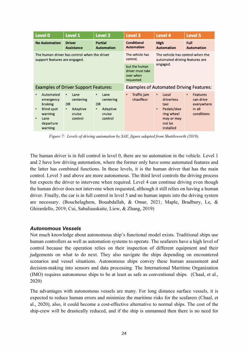
Figure 7: Levels of driving automation by SAE, figure adapted from Shuttleworth (2019).
The human driver is in full control in level 0, there are no automation in the vehicle. Level 1 and 2 have low driving automation, where the former only have some automated features and the latter has combined functions. In these levels, it is the human driver that has the main control. Level 3 and above are more autonomous. The third level controls the driving process but expects the driver to intervene when required. Level 4 can continue driving even though the human driver does not intervene when requested, although it still relies on having a human driver. Finally, the car is in full control in level 5 and no human inputs into the driving system are necessary. (Bouchelaghem, Bouabdallah, & Omar, 2021; Maple, Bradbury, Le, & Ghirardello, 2019; Cui, Sabaliauskaite, Liew, & Zhang, 2019)
Autonomous Vessels Not much knowledge about autonomous ship’s functional model exists. Traditional ships use human controllers as well as automation systems to operate. The seafarers have a high level of control because the operation relies on their inspection of different equipment and their judgements on what to do next. They also navigate the ships depending on encountered scenarios and vessel situations. Autonomous ships convey these human assessment and decision-making into sensors and data processing. The International Maritime Organization (IMO) requires autonomous ships to be at least as safe as conventional ships. (Chaal, et al., 2020)
The advantages with autonomous vessels are many. For long distance surface vessels, it is expected to reduce human errors and minimize the maritime risks for the seafarers (Chaal, et al., 2020), also, it could become a cost-effective alternative to normal ships. The cost of the ship-crew will be drastically reduced, and if the ship is unmanned then there is no need for

25
facilities to support humans. Storage room for the transportation goods will thus increase. (Tam & Jones, 2018)
Unmanned Aerial Vehicles Unmanned aerial vehicle (UAV), commonly known as drones, are usually remotely controlled by humans but could also be autonomous (Johnsen, Hoem, Jenssen, & Moen, 2019). Drones have the potential to provide important applications to society, such as surveillance, medical delivery, disaster management, patrolling and agricultural aid (Johnsen & Evjemo, 2017). To date, autonomous UAV are still limited in use for civilian purposes, this is mainly due to safety questions for people or properties. In addition, there is a lack of regulations and policies that govern safe usage and operation. (Allouch, Koubâa, Khalgui, & Abbes, 2019) One security issue UAV has that does not apply to other vehicle types is the sizing of the drones. They are so small that it is possible to pick it up and steal it. (Johnsen, Hoem, Jenssen, & Moen, 2019)
Automated Train Automated trains are rail systems which have no conductor nor any accompanying staff. It is also called Unattended Train Operation (UTO). These automated trains have already been in motion since 1980 and have 48 lines across 32 cities. They require substantial infrastructure cost, but will in the long run lower operation cost, increase reliability, increase capacity and are energy efficient. Data has also showed that they have exceptionally high safety, very few incidents per person per kilometer have been reported and never any loss of lives or significant harm. (Johnsen, Hoem, Jenssen, & Moen, 2019)
4.1.2 Risk Assessment Steps As described in chapter 2.2 Risk Assessment, the risk assessment process contains of three steps; Identification, Analysis and Evaluation. Figure 8 shows which part of the steps the articles attended to. Some articles covered more than one step. As seen, not even one article evaluated the analysis results. In a few articles, the word “risk evaluation” did occur, but their definition of evaluating the risk did not include comparison to a risk criterion or propose any method of charting the risk. Although, some articles did suggest treatment and mitigation strategies for identified risk areas.
Seeing that no articles did ask the question if the risk is at an acceptable level or not, it indicates that the risk management process in this field is not yet fully mature. Many systems of autonomous vehicles are still new, to understand such a complex system and to identify all potential risk takes time. The development of evaluation models might still need a little bit of time.

26
Figure 8: The three risk assessment steps covered in articles from Group 1 and Group 2.
4.1.3 Risk Types Risk assessment on autonomous vehicles usually either focus on risk due to attacks or due to accidents, called security risk or safety risk respectively. Sometimes articles also address the connection between them. Both security and safety are of course vital for vehicle development. Figure 9 illustrates which type of risk the articles from each group address, note that some address both types. A total of 18 articles were about attacks and 24 about accidents.
Figure 9: The type of risk covered in the articles from Group 1 and Group 2.
8 7
10
19
1
Identification Analysis Evaluation N/A0
5
10
15
20
25
30
Risk Assessment Steps Covered
Group 1 Group 2
6 8
12
16
0
5
10
15
20
25
30
Attack Accident
Type of Risk
Group 1 Group 2

27
4.1.4 Group 2 Subject in Focus Articles from Group 2 discuss one or more risk assessment steps for an autonomous vehicle, what divides them from Group 1 is that they focus on one particular vehicular area. Group 1, on the other hand, have a holistic view of the vehicle. Some risk assessment methods or frameworks used in Group 2 are too specific to be used in this thesis, i.e. a model that treats severity of information leakage and its recovery time due to cyber attacks (He, Meng, & Qu, 2020) and another about how well the perception layer for deep learning is working (McAllister, et al., 2017). As the thesis’s aim is to have a holistic view of the risk assessment process, the models in Group 2 are consequently considered to be beyond the scope of this paper.
Nevertheless, the subject in focus in Group 2 are presented in Figure 10. Tactical Safety Reasoning concerns the automated driving decisions and how to plan safe maneuvering (Serban, Poll, & Visser, 2018). Within this category, the ethical aspects of decision-making are also included. For example, some accidents will unavoidably cause harm to somebody or to infrastructure, who or what the victim should be to harm is a moral dilemma. One risk analysis method is using cost function algorithm. (Geisslinger, Poszler, Betz, Lütge, & Lienkamp, 2021) Machine Learning is a part of artificial intelligence (AI), which is in turn a technology that will become more widely installed in vehicles, especially autonomous ones. Its task is to learn from data, identify patterns and make real-time decisions (Deng, et al., 2021). Autonomous vehicle industry will need a lot of testing systems, and three articles from Group 2 addressed the development and risk assessment of Testing. Other articles focused on crashing safely, which is the category of Collision. Cyber Security is a hot topic, as becoming more autonomous opens up more potential attack surfaces (Bolbot, Theotokatos, Boulougouris, & Vassalos, 2020). IoT stands for Internet of Things, and is a network that connects vehicle components with each over the internet and exchanges data (Le, Maple, & Watson, 2018). Cyber-Physical Systems (CPS) is an engineered system which integrate software and hardware components to influence physical processes (Guzman, Kufoalor, Kozine, & Lundteigen, 2019). The one article that focused on Software particularly researched the integration of components’ software (McAllister, et al., 2017). Communication System and Radar are components in autonomous vehicles. The article about Societal Acceptance identifies the perceived risks the public feels with autonomous cars (Howard, Kral, Janoskova, & Suler, 2020). The last category, Human-Cyber-Physical system (HCP) is about the cyber-physical system’s interaction with humans (Sadigh, Sastry, & Seshia, 2019).

28
Figure 10: Subject in focus for articles in Group 2.
4.2 In-Depth Analysis Articles from Group 1 did either treat risk identification or risk analysis, some included both. Many also provided a system description of the vehicle. Creating an appropriate detailed system description should be concretized before conducting a risk assessment. Figure 11 shows the collected risk models found in Group 1. Some models are not as publicity available as others, as those were a part of the authors own constructed frameworks.
Figure 11: Risk models and frameworks presented in articles from Group 1.
0
1
2
3
4
5
6
Tacti
cal S
afety
Reaso
ning
Machine Le
arning
Testi
ng
Collision
Cyber
Secu
rity IoT
CPS
Softw
are
Communicatio
n Syste
mRad
ar
Socie
tal Acce
ptance HCP
Subjects
0
1
2
3
4
5
6
7
8
STRIDE
ATA
Literat
ure Review HazI
dHazO
pFM
EAET
AFT
ACCA
STPA
Taxo
nomyS&
S
Defense Graph
CVSS BNDTD
MHARA
STEC
A
Functi
onal Sa
fety
Risk Models and Frameworks

29
Some models included both risk identification and risk analysis, some even mentioned risk evaluation even though none provided any method of actually evaluating the risk. Models can thus be cross-sectional when it comes to risk assessment’s three distinguished steps. However, analysis models either appear in safety analysis or security, if it does not explicitly say that it is a combined method. Safety and security are almost always treated differently with different methods. The following subchapters are hence divided according to safety risk methods, security risk methods and combined methods. Before that, a chapter describing the context and system of autonomous vehicle will be presented first.
Models which are included in safety risk methods are STPA, STECA, FTA, Functional Safety Methodology and Bayesian Network. The security models that will be explained are ATA, STRIDE, CVSS, Taxonomy and Defense Graph. The only combined method is S&S. The other methods in Figure 11 which are not explained in detail in further subchapters will be provided with a brief explanation below.
Literature Review is one of the most used risk identification method found in the research papers. Authors have simply searched other literature to provide for their own studies. As this method is quite fundamental, it will thus not need to be explained further. Hazard Identification (HazId), Hazard and Operability Study (HazOp), Failure Mode and Effects Analysis (FMEA), Event Tree Analysis (ETA) and Cause-Consequence (CCA) were briefly mentioned by Gleirscher (2017) as models that can be used to identify risk. HazId is a well-known systematic identification method which uses brainstorming in a multi-disciplinary team to find potential hazards (Vista Oil & Gas, 2019), whereas HazOp identifies hazards through deviations from the system’s design or operating intentions by using sets of “guide words” (PQRI, 2015). FMEA is a step-by-step approach for identifying failures in a design, manufacturing or assembly process. The FMEA method guides the performing analysis team to find functions and their failure modes. (ASQ, 2021) An ETA is an inductive procedure that maps out the possible outcomes resulting from an accidental event (Rausand, 2005) and the aim of a CCA is to create a logical diagram of possible outcomes arising from a combination of selected input events (Saud & Israni, 2012).
The last two models that this thesis will not cover is Hazard Identification and Risk Assessment (HARA) and Dynamic Tactical Decision Making (DTDM). The basis of HARA is to identify potential hazards and categorize them according to severity, probability and controllability (Chomicz, 2017). DTDM is a framework based on HARA but with a more dynamic approach (Khastgir, et al., 2017).
The reason behind that some methods are explained more and some less is based on their relevance for the thesis and how well described they are in their respective article. Those not included are either just briefly mentioned, are too fundamental or not relevant.
4.2.1 Context and System Description There are several ways of describing the system and context. Many authors have different names for this step of the risk assessment, i.e. reference architecture (Maple, Bradbury, Le, & Ghirardello, 2019) and basic technical principles (Hu, 2020). All these, however, aim to

30
describe autonomous vehicle systems in a tangible way by modularizing the system into components.
When generating a system model, many authors collect clusters of components and form them into subsystems. Each subsystem has a main function to provide to the vehicle. Bhavsar et al. (2019) are classifying the system into four major groups; hardware, software, communication and human-machine interface. Hardware includes all types of sensors in order to perceive the environment correctly, this could be camera, LiDAR (stands for Light Detection and Ranging and is an optical measuring instrument) and thermometers. Software consists of data collection and processing procedures. Communication includes Vehicle-to-Everything (V2X) Communication, which could for example be Vehicle-to-Vehicle or Vehicle-to-Infrastructure, but also Wi-Fi and cellular communication. Lastly, human-machine interface consists of personal assistant system, which could i.e. be voice recognition. (Bhavsar, Das, Paugh, Dey, & Chowdhury, 2017; Maple, Bradbury, Le, & Ghirardello, 2019)
Hu (2020) and Wang et al. (2020) have three major levels; Perception Layer, Decision Layer and Control/Action Layer. The perception layer includes all the components that make the system possible to detect, trace and localize the vehicle itself and the environment around it. This layer includes data receiving and data processing within software, but also sensors and actuators. Next, the Decision Layer is the layer that plans the maneuvering, with i.e. steering and acceleration, based on a situational assessment from the Perception Layer. Lastly is the Control/Action Layer, which regulate actuators to throttle, brake, park, etc. (Wang, Zhang, Huang, & Zhao, 2020; Hu, 2020)
Yet another way to define subsystems is made by Maple et al. (2019). They split the system into seven categories; Functional, Communication, Implementation, Enterprise, Usage, Information and Physical. The Functional subsystem regards the component’s tasks, Communication about their interaction, Implementation is about the implementation of the components, Enterprise regards the relation between organizations and users, Usage is about the expected usage of the system, Information regards the information handled by the system and Physical is about the physical objects in the system and their connections. Functional, Communication and Implementation are the core categories when creating an overviewing system description, as these cover the most essential measures for the system’s operations. (Maple, Bradbury, Le, & Ghirardello, 2019)
As seen, there are several ways to describe a complex system such as an autonomous vehicle. The tightly-coupled networks between components are another aspect which could be necessary to incorporate into the system description, depending on the detailing of the risk analysis. There exists no standard model for an autonomous vehicle, regardless if it is a car or ship, it thus important to create one suitable for the risk assessment. Too detailed system model could create confusion and making the risk assessment more difficult than it has to be, and too little details could lead to an incomplete risk assessment that does not cover even the most essential parts. Hence, the system description should be designed after the risk assessment goals.

31
Some articles presented their version of a system model. Those who are deemed as multifunctional and have a holistic approach have been compiled and can be viewed in Appendix A2. Furthermore, Table 1 includes a few autonomous vehicle components and functions and their description of operation.
Table 1: Description of operation of some autonomous vehicle components and functions. This table is summarized from Maple et al. (2019).
Component/Function Description of operation
Wireless Communications Vehicles could be equipped with antennas for
i. AM, FM and/or DAB radio ii. Wi-Fi
iii. V2X communications iv. Cellular communications v. IoT
Wireless communications are vital for cooperation with other vehicles and with the vehicle’s users.
Physical Input/Outputs Consists of ports contained within the vehicle, such as
i. USB ii. OBD-II
iii. Audio connections Vehicle Sensors Used to obtain the state of the environment
and to build a model of the world. Example of sensors:
i. GNSS ii. LiDAR
iii. Wheel rotation sensors iv. Parking cameras v. Thermometers
vi. Hygrometers Data Storage For storing data such as
i. Firmware and software ii. Maps and navigation information
iii. Music and videos for the entertainment system
Usually stored in multiple locations locally, but also utilizes the Cloud and the Edge.

32
Data Analysis Data acquired from sensors and to process stored data will need analyzation. Some parameters which will be needing data analysis are:
i. Localization ii. Object identification
iii. Sensor fusion iv. Action engine
Energy System Charges energy and supplies it to the vehicle. Ensuring that the vehicle’s batteries are consumed safely.
Actuators Components which actions impact the physical world, such as
i. Applying the brakes ii. Operating air conditioning
iii. Unlocking car doors Monitoring Verifies and analyzes different functions to
ensure adequate operations.
Infotainment Manage the information and entertainment system.
Human-Machine Interface Devices that allows a person to actively interact with the system, such as
i. Steering wheel ii. Brake or accelerator pedal
iii. Dashboard controls
4.2.2 Security Risk Methods This section describes the security risk assessment methods found.
Attack Tree Analysis The vulnerable components are called attack surfaces and the actions of performing the threat are attack paths (Bouchelaghem, Bouabdallah, & Omar, 2021; Maple, Bradbury, Le, & Ghirardello, 2019; Sommer, Dürrwang, & Kriesten, 2019). One method to map out attack surfaces for a potential threat is by creating an attack tree (Maple, Bradbury, Le, & Ghirardello, 2019). Attack Tree Analysis (ATA) is a Risk Identification method that traces the attack path or a threat to specific components. Conducting an ATA consists of five steps, which is illustrated in Figure 12 and explained below (Maple, Bradbury, Le, & Ghirardello, 2019):

33
1. The basis of the tree is the attacker’s goal. This is the node that generates the whole analysis.
2. The tree branches out to determine the attack functions, in other words the components that ultimately need to be compromised for the goal to be achieved.
3. The next outbranching is to find the attack surfaces and entry points that the attackers could exploit.
4. Determining the assets that could be affected is the next step. The possible attacks on these assets should also be defined.
5. The last step is to consider the attackers capabilities, but also resources and presence. If there are paths that are considered too unlikely to happen during the construction of the tree, prune these branches. The tree should only include paths that have a chance of happening.
Important to note when creating the attack tree is that a component is rarely attacked by itself, but attacked simultaneously or being used as an aid to further attack other components (Maple, Bradbury, Le, & Ghirardello, 2019).
Figure 12: A generic attack tree, figure adapted from Maple et al. (2019).
STRIDE A way to classify the threats of an attacker is by using STRIDE (Bouchelaghem, Bouabdallah, & Omar, 2021). STRIDE stands for of Spoofing, Tampering, Repudiation, Information disclosure, Denial of service and Elevation of privileges. Spoofing, in autonomous vehicles, is when an attacker masquerades a legitimate vehicle and/or disseminates fake information. An

34
attacker is Tampering when the messages exchanged between vehicle, sensor data and electronic control unit’s firmware are being altered. If a vehicle falsely starts to deny having performed a certain action or having been involved in a reported event, it has undergone a Repudiation. Information disclosure when an attacker gets unauthorized access to exchanged messages or to sensitive information. If sensor data acquisition or timely message dissemination, i.e. warnings, are being prevented to performed, an attacker could have performed a Denial of Service. The last classification, Elevation of privileges, is when improper commands are being sent to the navigation system and the attacker gains unprivileged access to the vehicle’s critical functions. (Bouchelaghem, Bouabdallah, & Omar, 2021).
STRIDE is usually used in the Risk Identification step. The aim of STRIDE is to define and group similar attacks into classes.
CVSS Common Vulnerability Scoring System (CVSS) is a risk estimation method within Risk Analysis that quantifies and prioritize the risks of identified threats. It is based on six metrics, which will be rated. The metrics are as follows (Bouchelaghem, Bouabdallah, & Omar, 2021):
• Access Vector – Regards the accessibility the attacker has to the attack surface. The more remote an attacker can be, the higher the vulnerability score;
• Access Complexity – Regards the complexity required to perform the attack. The lower the complexity, the higher the vulnerability score;
• Confidentiality Impact – Regards the impact on confidentiality of a successful attack. The higher the impact, the higher the vulnerability score;
• Integrity Impact – Regards the impact on integrity of a successful attack. The higher the impact, the higher the vulnerability score;
• Availability Impact – Regards the impact on availability of a successful attack. The higher the impact, the higher the vulnerability score;
• Collateral Damage Potential – Regards the damage of the attack. The more life-threatening and damage on property, the higher the vulnerability score.
Starting off with an identified threat, each metric will be rated from 0 to 10 when applied to the threat. The average score of the metrics corresponds to a level of severity. Low severity has scores ranging 0.0-3.9, medium between 4.0-6.9 and high between 7.0-10.0. (Bouchelaghem, Bouabdallah, & Omar, 2021)
Automotive Security Taxonomy After identifying security issues with the system, the research should be stored in a way that is retrievable and contains all necessary information. Structuring the Risk Identification step in an efficient way will decrease future work when this step needs to be revised. Automotive Security Taxonomy is a classification method for filing existing attacks. A classification of

35
attacks is valuable for conducting a security testing process and also for the development phase, in order to have knowledge about past threats and attack paths. (Sommer, Dürrwang, & Kriesten, 2019)
Figure 13 shows the categories that were suggested to be included in the taxonomy and an explanation is provided for each category. The authors considered these categories as comprehensive, all necessary information for future usage is covered within this taxonomy. Furthermore, the authors assume that the accident to be documented is found by literature reviews, hence the category Reference and Year. (Sommer, Dürrwang, & Kriesten, 2019) CWE, which appears in the category Vulnerability, stands for Common Weakness Enumeration and is a community-developed list of common software and hardware weakness types. It is being used for categorizing vulnerability. CVSS is a way of evaluating the threat level of a vulnerability, whilst CWE prioritizes them. (CWE, 2021)
Figure 13: An explanatory figure of what content the respective categories should include in the Automotive Security Taxonomy, figure composed from Sommer, Dürrwang & Kriesten (2019).
Bayesian Defense Graphs A Defense Graph is a representation of an attack and all paths through the system that lead to a countermeasure. A Bayesian Defense Graph supplement further with likelihood estimations. Creating one consists of three main steps (Behfarnia & Eslami, 2018):
1. Forming a defense graph – The vulnerable components, which are the ones that could jeopardize the security of the vehicle, are to be defined. In order to prevent exploitation of these components, a set of defense techniques are formed. Afterwards, a defense

36
graph can be created. The attack surfaces should be equipped with defense techniques, also called countermeasure, together with the elements which make the techniques possible.
2. Threat identification and risk assessment – Even though countermeasures are implemented for a vulnerable component, the component can still be successfully exploited. It is therefore important to identify all threats. Risk assessment pursues once the threats are identified. The two fundamental parts of a risk assessment, according to the authors, are severity and likelihood of the threats. Severity is defined by the harm of the stakeholders and likelihood is based on the probability of a successful attack.
3. Bayesian network analysis – It is a graphical method of probabilistic interference of relationships between a set of variables, in this case the components and countermeasures. A network of the countermeasures’ functionality and their cause-effect relationships are captured, as illustrated in Figure 14. C is representing a vulnerable component and A and B are countermeasures. To yield a successful attack on C, the threat must bypass A and B without being detected first. Figure 14 indicates a conditional probability table, where D stands for detected and ND for not detected. True (T) signifies a successful detection and false (F) an unsuccessful detection, 𝜃 stands for probability ranging from 0-1.
Figure 14: Bayesian network analysis, figure adapted from Behfarnia & Eslami (2018).
4.2.3 Accident Risk Methods This section describes the safety risk assessment methods found.
STPA Systems-theoretic process analysis (STPA) is a risk management framework. It has a systemic outlook and is an iterative process, making it suitable for the vehicle’s development and design phase (Chaal, et al., 2020). Its point of departure is in the accident scenario, the accident process which includes design errors and component interaction factors in the analysis. Eventually, it will lead to controlling the vehicle’s safety constraints. (Hu, 2020; Valdez Banda, et al., 2019)

37
Figure 15: STPA process steps, figure adapted from Hu (2020).
Figure 15 illustrates the steps of conducting a STPA and a brief explanation of the process is provided below (Hu 2020; Valdez Banda, et al., 2019; Chaal, et al., 2020):
1. Accident – The specific accidents that will be covered in the analysis are defined.
2. Danger – The hazards which could lead to the accident are identified. There might exist a certain set of conditions that are dangerous in that particular state. Severity and consequences of the dangerous events should also be investigated.
3. System Safety Constraint – The system behavior requirements for it to avoid or mitigate the identified hazards are defined. The mitigation actions can be divided into four categories:
a. Attempts to reduce the consequences of the accident;
b. Attempts to reduce the likelihood that the hazard will turn in to an accident;
c. Attempts to reduce the likelihood of the hazard occurrence;
d. Attempts to eliminate the hazard occurrence.
4. System Control Structure – The control system is established and the controls that have a significant effect on the safety of the vehicle are identified. The control structure is a functional model of the vehicle, composed of control loops. There are five main elements within the structure:
a. The controllers;
b. The controlled processes;
c. The control actions;
d. The feedback;
e. Other inputs and outputs from components.
5. Unsafe Control Behavior – The unsafe control behavior or unsafe control action (UCA) that could lead to a hazardous state is detected.
6. Cause Analysis – Define why and how the UCA can occur.
7. Controlling Security Constraints – Ascertain how the control behavior could stay within the established constraints and ensure that they are.

38
STECA In the early conceptual design phase when there is limited knowledge about the vehicle’s functional system, it might be difficult to establish the system control structure as needed in many risk assessment frameworks. System Theoretic Early Concept Analysis (STECA) is a method attempting to tackle this issue. In a nutshell, it uses the Concept of Operations (ConOps) document to create a safety control structure of the system concept. (Chaal, et al., 2020) A ConOps describes the system’s operations and its characteristics from an operational perspective, in order to facilitate an understanding of the system’s goals. The six steps of STECA in Figure 16 should be done iteratively. Identifying system hazards is about mapping out accident and hazards the system be found in. The system safety constraints that can be violated through the hazards should thus be studied. Next, to identify the control concepts, the ConOps document needs to be examined in order to establish the safety requirement for each entity in the control loop. The step of identify hazardous scenarios and casual factors is to detect all the paths the accident can propagate successfully through. Afterwards, it is not enough to label components either as “safe” or “unsafe”, but to reason prevention and mitigation methods for the identified hazardous scenarios. This is done when deriving refined safety constraints. The last step, to refine, modify control structure is basically refining and modifying the system based on findings from previous steps. (Fleming & Leveson, 2015)
Figure 16: The steps of STECA, figure adapted from Chaal et al. (2020).
Fault Tree Analysis Fault Tree Analysis (FTA) is a method of identifying the hierarchical failure of a system and is used to estimate risk. The tree starts off with a top-level event and its estimated failure probability, then it branches out and divides up the different factors, called basic events, contributing to the top-level failure. Each step is provided with a failure probability. The hierarchical sequence of events, that is the top-level event to one of the bottom-level events, is a cut-set. These cut-sets and their probabilities could be ranked against each other to create a risk hierarchy. Thus, it is a method for prioritizing areas in order to improve the safety

39
performance. (Bhavsar, Das, Paugh, Dey, & Chowdhury, 2017) Figure 17 illustrates a basic FTA.
A fault tree could be validated in two ways; qualitatively and quantitatively. The qualitative method studies the basic events and their connection to the top-level event. The quantitative method considers the failure probabilities, i.e. comparing it to real-world data. (Bhavsar, Das, Paugh, Dey, & Chowdhury, 2017)
Figure 17: A generic Fault Tree without probabilities, where the dotted line marks a cut-set.
Functional Safety Methodology The functional safety methodology is based on ISO 12100 and ISO 13849. The steps, which are illustrated in Figure 18, are described below (Allouch, Koubâa, Khalgui, & Abbes, 2019):
1. System Limits Specification – The first step of the risk analysis. The authors suggested limitations such as physical, temporal, environmental, behavioral and networking limits.
2. Hazard Identification – The hazards could be categorized as internal and external. It could be constructed with the help of reactive methods, which are incident and accident databases, survey or maintenance report.
3. Risk Estimation – Needs to be determined by severity and probability. There exists four qualitative severity levels ranging from negligible, marginal, critical and catastrophic, and five qualitative probability levels ranging from improbable, remote, occasional, probable and frequent. Using a risk assessment matrix, an estimation of the risk can be made, ranging from low, medium, serious and high risk.
4. Risk Evaluation – If all of the risks are acceptable, then nothing needs to be done. If not, there is a need to proceed.
5. Risk Reduction Measures – To reduce the non-acceptable risks, three steps could be followed:

40
a. Inherently Safe Design – Follow safe design approaches to reduce risk to an acceptable level in the design phase, including prototyping, verification and inspection before usage.
b. Safeguarding and Protective Measures – If the risk cannot be eliminated, measures should be implemented to mitigate the consequences of the risk.
c. Information For Use – This is a safety measure in the form of spreading information about the potential risk to the user in order to keep it to an acceptable level.
6. Safety Functions Identification – The safety function is best identified from the previous step.
7. Performance Level Required Determination – The performance level required to attain the risk reduction for each safety function. It is determined by the severity of possible injury, frequency of exposed hazard and the possibilities of avoiding the hazard. The performance level, based on the three parameters, can be graded a-e, see Figure 19. The performance of the safety must be higher with higher risk.
Figure 18: The steps of the Functional Safety Methodology, figure adapted from Allouch et al. (2019).

41
Figure 19: The calculation of performance level required, figure adapted from Allouch et al. (2019).
Bayesian Network Bayesian Network (BN) is a quantitative risk analysis method. Steps are described below (Allouch, Koubâa, Khalgui, & Abbes, 2019):
1. Topology – A BN is frequently represented with a target, observable and intermediate nodes. The target node is the targeted accident (i.e. a crash), intermediate nodes are clusters of main causes of the accident (i.e. crash due to external causes and internal causes) and observable nodes are the directly observable faults (i.e. GPS loss, loss of electrical power, component failure, weather, etc.) . Figure 20 illustrates a BN topology.
Figure 20: A Bayesian Network Topology, figure adapted from Allouch et al. (2019).

42
2. Data Collection – Each observable node will have two states, YES or NO, measured by a probability. YES corresponds to the fault is present, and NO to absent faults. This step aims to collect the necessary data to assign the probabilities for each observable fault. The intermediate nodes will then have a probability output of four states; frequent, probable, occasional and remote. Lastly, the target node will have five states; neglectable, low, medium, high and very high probability of occurrence.
Figure 21: Probability for the nodes in a Bayesian Network analysis, figure adapted from Allouch et al. (2019).
Note that the probabilities in the figure is just an example and the calculation is not true.
3. Updating Data – Data should be up to date and if the probability changes in any of the nodes, the target node should also be updated consequently.
4. Scenario Analysis – By projecting different scenarios, like the accident is taking place under a specific external condition, and changing probabilities for different nodes accordingly, the parameters that have high impact on the risk can be identified.
5. Sensitivity Analysis – Sensitivity analysis is a great overview of the nodes that have the highest contribution on the target node.

43
4.2.4 Combined Method In only one article did safety and security appear together in a model. All other models treated them separately and was explicitly design for either accident or attack. Some models however, such as attack tree and fault tree, are basically the same. Still, they are distinguished from each other as they specialize in different fields of risk. This subchapter presents the only combined method found about current research on risk assessment on autonomous vehicle.
S&S Safety and Security Integration method (S&S) is a model which incorporates safety and security in a risk matrix (Cui, Sabaliauskaite, Liew, & Zhang, 2019). The matrix, which is illustrated in Figure 22, contains six hierarchies:
1. Functions (F) – The identified functions of the system.
2. Structure (S) – The identified components that form the system’s hierarchical structure. Matrix SF corresponds to the relationship between the system’s functions and structure. The marking on the SF matrix means that there is a relationship between the elements.
3. Failures (B) – The identified failures of the system. Matrix BS corresponds to the impact of the failures on the structural component. The impact is regarded as high, medium or none. Matrix BF can be obtained by BF=BS∙SF.
4. Attacks (A) – The identified attacks that can lead to a system failure. Matrix AB determines which failures that could outbreak due to a successful attack, also regarded as high, medium or no impact. The attack’s impact on the structure can be obtained by AS=AB∙BS and the impact on the functions from AF=AS∙SF.
5. Safety countermeasures (X) – The identified safety countermeasures that can prevent or mitigate failures. Matrix XB corresponds to the failures that are covered by the safety measures, the coverage is ranging from full, partial and none. The safety measure coverage by attacks can be obtained by XA=XB∙ABT, where ABT is the transposed matrix of AB. The coverage of the safety measures on the structure can be obtained by XS=XB∙BS and the functions by XF=XS∙SF.
6. Security countermeasures (Z) – The identified security countermeasures that can prevent or mitigate attacks. Matrix ZX corresponds to the interdependencies between the security and safety measures. There are three categories of interdependency; complement (one countermeasure complement or support another), conflict (one countermeasure conflict or diminish another), independence (two countermeasures are mutually independent). Matrix ZA corresponds to the attack that are covered by the security measures, the coverage is ranging from full, partial and none. The coverage of failures by security measures can be obtained by ZB=ZA∙AB. The coverage of structure by security measures can be obtained by ZS=ZA∙AS and functions by ZF=ZS∙SF.

44
Figure 22: Safety and Security integration method matrices, figure adapted from Cui et al. (2019).
4.2.5 Identified Risks This subchapter presents the identified risks mentioned in the articles from Group 1. These risks are also divided between safety and security risks. Safety risk usually originates due to hazards or unwanted situations, the situations can elaborate and become accidents if there are faults in the vehicle system or if the system is lacking the ability to properly manage the hazard (Amro, Kavallieratos, Louzis, & Thieme, 2020). Table 2 lists identified hazard sources that could take place during the design and manufacturing phase of autonomous vehicles and cause accidents. All hazards described in Table 2 are generic, as it is very system dependent and it thus hard to pinpoint the exact cause factor.
Table 2: Some hazard sources for autonomous vehicle, table adapted from Allouch et al. (2019).
Hazard Example
Mechanical hazard Mechanical fastener failure, motor failure, actuation failure
Thermal hazard Freeze, explosion
Electronic hazard Power loss, saturation, overflow
Algorithmic hazard Verification error, decision-making error, delayed responses
Technical hazard Battery depletion, loss of control, loss of transmission

45
Software Control system failure, autopilot error, bugs in code
Hardware Sensor failure, processor failure
Interference Electromagnetic interference
Security risks are caused by incidents involving attackers. The attackers usually use a variety of tools, locate an area that is vulnerable, and then perform a malicious action on a chosen target (Sommer, Dürrwang, & Kriesten, 2019). Figure 23 presents roles of attackers, the common tools used, vulnerability areas, attacker’s common actions and targeted areas, as well as the results and objectives the attackers strive to achieve.
Figure 23: A chart of a malicious incident’s components, figure adapted from Sommer et al. (2019).

46
Security issues are more standardized than safety issues. As attacks are set up from the outside, it can be performed in any vulnerable system. Safety issues, however, are harder to ascertain until an accident takes place. (Amro, Kavallieratos, Louzis, & Thieme, 2020) Hence, there exists a lot more documented potential attacks than potential accidents. A list of possible attacks on different autonomous vehicle components can be viewed in Appendix A3.

47
5 Consultative Interviews Results Two interviews have been held, one with a consultant working with System Safety and one with a senior advisor working with safety for governmental and industrial projects. One interviewee has worked with Remotely Operated Underwater Vehicle (ROV) and Autonomous Underwater Vehicle (AUV). Both ROV and AUV do not require a human operator in the vehicle, as they are used to access difficult underwater areas. ROV can operate differently, one way is to monitor the environment which the operator can see with the help of i.e. cameras and then the operator maneuvers the vehicle through a console. Another way is by commanding navigation points where the ROV will travel to. The other interviewee has worked with autonomous functions and automated systems, which will execute operations that are pre-programmed such as UAV navigating a route based on commands, but not with fully autonomous systems.
5.1 Standards and Methods Used The consultant stated that when working in System Safety, security issues are not considered as this field is another department’s business. The safety risk methods and standards the consultant has worked with regarding autonomous vehicles are US military standard MIL-STD-882, the UK Ministry of Defense’s Defense Standard (Def Stan) 00-56, Swedish Armed Forces’ Materiel Administration handbook of System Safety (H SystSäk), the International Electrotechnical Commission (IEC) standard IEC61508 for Functional Safety, Safety Integrity Level (SIL) and regulations for CE marking. The first three standards and handbook can be used as a guidance for developing and implementing a system safety program for military purposes (DOD, 1993; Ministry of Defence, 2007; Försvarsmakten, 2011). The IEC standard covers electrical and electronic safety-related systems, of what should be considered when those systems are in use in order to carry safety functions (SiS, 2010), and a CE marking signifies that the product meets high safety, health and environmental requirements (EC, n.d.). Last but not least, SIL is a measure of safety system performance and classifies safety into four classes, where a high level represents high safety. The measurement of safety is dependent on probability of failure on demand. (MSA, n.d.)
The senior advisor proposes STPA as a risk assessment method to work with complex systems, as autonomous vehicles are, due to the fact that the method covers different safety perspectives like the technical system, the autonomous control system, the environmental perspective and human factor. Autonomous systems can learn and change through experience, to adapt to the new situation or environment, which makes it hard to perform risk assessment on due to the everchanging system. Normally, if an accident takes place, it is possible to backtrack and realize where the mistake originated from, which is not as possible for a changing system. This is something that STPA could cover.
To present results to the consultant’s clients, a Risk Matrix is normally used. The Risk Matrix is composed of likelihood on one axis and consequences on the other. It is the clients that select which combination that categorizes as “acceptable”, “limited acceptable” and “unacceptable”. The consequences are usually based on the severity of afflicted harm to people, harm to

48
properties and sometimes harm to the environment. Likelihood can be estimated qualitatively or quantitively, Fault Tree Analysis is the primary quantitative method according to the consultant.
5.2 The Risk Management Process Being involved early in the product’s project plan is ideal, in order to influence the initial design and concept according to safety concerns. Moreover, a safety management plan can be implemented as well. Such a plan establishes a continuous safety management work, making it possible to compile a risk log or hazard log and to follow up on safety measures. Documenting in a risk/hazard log can be useful for other similar projects. Less time needs to be spent on identifying risk from start, instead, the logs can be used as “Lessons Learned”.
However, not all projects are ideal. The consultant mentioned that they sometimes receive an inquiry to perform safety check after a product’s release due to a hazard, even though it is not as common. Widespread modifications are not possible at that stage. A few things that can mitigate or reduce the identified risk is to i.e. include a warning segment in the product’s manual, provide recommendations of the product’s usage (maximal depth and allowed sea state) and if possible, make smaller design alterations.

49
6 Framework Compilation Safety and security risk are often divided as two separate fields, as seen in both scientific papers and in the industry. But are they really that different from each other?
Traditional definition of risk is mostly based on probabilities and frequency – measurements not quite suitable for describing a terrorist attack but works well for safety risk. Security risk definition, on the other hand, rests in three factors; assets/values, threats and vulnerabilities. A combination of the three creates a security issue. However, uncertainty is a component that permeates all malicious attacks and is thus fundamental for security as it is for safety. (Amundrud, Aven, & Flage, 2017) Uncertainty is, as mentioned in a previous chapter, the foundation for the new risk perspective. The new definition of risk in SRA Glossary includes both safety and security (SRA, 2018). Security and safety have been seen as separate fields before but are nowadays considered interlinked due to the new risk perspective, they should thus not be treated in isolation from each other. It is possible that a security issue originates from the same problem area as another safety issue. Consequently, to perform a comprehensive risk assessment in a system, the connection between safety and security must be present.
As seen from the results of the Scoping Study, the development of risk assessment methods for autonomous vehicle is scattered. Many different methods were mentioned but none of these appeared as an apparent option to use in this kind of context. From the SRA Glossary, modern definition of risk is dependent on consequences, uncertainty and the background knowledge for the risk (SRA, 2018). Some of these traits are not evidently included in the articles and strong connection to risk science has not been found. Moreover, the risk assessment for autonomous vehicle is an applied risk analysis, due to the fact that it addresses both risk science and the science of autonomous vehicle, it should thus be supported by a fundamental risk analysis and also provide back to it with new insights. This is not currently achieved. If a framework could incorporate this and also include the three traits from SRA Glossary, a stronger connection to modern risk science can be made. Establishing a strong connection to risk science can in turn facilitate the integration with other risk management aspects, such as risk aggregation (Bjørnsen & Aven, 2019), continuity management (Hassel & Cedergren, 2019) and resilience (Aven, 2018).
This framework will treat both safety and security risk and have a more present connection to risk science. It will also include all three steps of the risk assessment process per the definition from ISO; Risk Identification, Risk Analysis and Risk Evaluation. One risk model that has the potential to cover all these points is S&S. On that account, the S&S model will be set as the point of departure for the proposed framework – with some elaboration and adaption, of course.
6.2 Customized S&S First of all, countermeasures are regarded as a part of Risk Treatment according to ISO, it does not belong in the Risk Assessment process (ISO, 2018). The matrices belonging to Safety Countermeasures and Security Countermeasures are thus beyond the scope of the proposed framework. Figure 24 is the result of this.

50
Functions and Structures describe the context and system and are essential to have identified before conducting the assessment. How the vehicle’s functions and structures should be defined is based on the particular vehicle in question, there is no general rule. Some enlightenment of how other researchers have done it and some components and functions to look after are presented in subchapter 4.2.1 Context and System Description and in Appendix A2. Important to note when mapping out the functions and structures is to be thorough, but at the same time to filter out unnecessary details. The more important functions and structures identified, the more comprehensive the assessment will be and also more time-consuming. It is a trade-off.
Figure 24: The customized S&S matrices.
The proposed framework, which is the network of matrices in Figure 24, will focus on the category Failures and Attacks and propose methods of identifying them and analyzing the impact on the vehicle. When all components to the four categories in Figure 24 have been established and the relationships within the matrices have been defined, the framework proposes a way of evaluating the results.
6.3 The RAAV Framework The Framework of conducting a Risk Assessment on Autonomous Vehicle (RAAV) consists of 11 steps. An example of the framework being used can be found in Appendix A4. The main structure of the RAAV Framework follows Figure 24. The steps are described below:
1. Identify Functions (F) – Identify the essential functions. Add as many as needed for the assessment’s scope.
2. Identify Structures (S) – Identify the essential components that form the system’s structure. Add as many as needed for the assessment’s scope.

51
3. Create SF Matrix – If the function’s components and the structure’s components influence each other, mark it in the matrix with a Connection dot, see Caption in Figure 24. The SF matrix facilitates the creation of the BF and AF matrices in the following steps.
4. Identify Failures (B) – Failures in the system can be identified through different methods. The framework proposes FTA, which is a safety identification method for locating failures through accidents/incidents. Its advantages are that it is suited for any system, the failures are identified through bigger events and the Fault Tree can be made as broad and profound as needed. Other methods such as HazOp, CCA and FMEA can also be used. They have a different approach than FTA even though they are also used to identify safety issues, but they also have their own advantages and whichever that is the most suited for the project can be used.*
5. Create BS Matrix – Find out which structure component might get affected by the failures. Analyze the impact. The framework proposes PLr from the Functional Safety Methodology for the analysis. Another method that can be used is Risk Matrix. Both the PLr and Risk Matrix can be performed qualitatively and quantitatively, they can cover a lot of aspects and can be used for ranking. The failures which affect the system structure severely are marked with a High Impact triangle and with Medium Impact triangle for less severe impact. It is possible to add additional impact levels if desired. As autonomous vehicle is a new field and data required to estimate the impact levels might be restricted, relying on assumptions and using other similar technology as a benchmark might induce uncertainties. Uncertainty Analysis is recommended to perform. Two uncertainty analysis methods suggested by the framework is Monto Carlo simulation and Sensitivity Analysis (Rausand, 2011).
6. Create BF Matrix – Create BF matrix by BF=BS∙SF. 7. Identify Attacks (A) – The framework proposes to use STRIDE to identify the attacks,
as this method is designed to cover different types of threats and Behfarnia and Eslami (2018) claim that STRIDE has proven to work well for autonomous vehicle (specifically cars).*
8. Create AS Matrix - Find out which structure component might get affected by the attacks. Analyze the impact. The framework proposes CVSS for the analysis. CVSS’ six metrics are designed to cover the essential aspects of the definition of security, which again are assets/values, threats and vulnerabilities. It can also be used for ranking. Note that the AS matrix is independent of the AB matrix. The original S&S method suggests to first create AB, which is the correlation between attacks and failures, and then form AS matrix based on AB. This way, only the structures that are affected by attacks which have a relationship with a failure will show. The attacks which do not affect any failures and are marked as Nil in the AB matrix, but might have high impact on the system structure, will thus be neglected. Consequently, the framework suggests to form the AS matrix independently. As with step 5, uncertainties in the selection of parameters for the impact levels might be present and Uncertainty Analysis is again recommended to perform.
9. Create AF Matrix – Create AF matrix by AF=AS∙SF.

52
10. Create AB Matrix – Find out which failures that could be triggered through an attack. Rate the impact level. The Framework proposes to base the rating on likelihood that the attack could trigger a failure. Uncertainty Analysis is also recommended.
11. Evaluate Risk – Risk evaluation is asking the question if the risk is acceptable and comparing it with a criterion. If there are several unacceptable risks, it is included in the evaluation to determine which one that should be treated first. (Aven & Renn, 2010) BF and AF are the two most important matrices to examine when performing the evaluation, as these two cover consequences that affect both structures and functions of the vehicle. To determine the most vulnerable functions, the two matrices can be added, AF+BF. While there exists no collective risk standard for autonomous vehicle in order to be determined as safe and secure, the framework proposes that the criterion for acceptable risk should be set as “at least as safe and secure as a conventional vehicle of the same type”. It is the same benchmark that IMO has set for autonomous ships. There are various risk metrics to determine this criterion, i.e. with Fatal Accident Rate, Expected Economic Loss or Individual Risk (Johansen & Rausand, 2014), to be used to compare autonomous vehicle to conventional vehicle. With the criterion defined, the matrix AF+BF can be evaluated if any risk needs further treatment or is considered acceptable. The Uncertainty Analysis should also be included in the evaluation. If a risk is considered unacceptable and the same function component is affected by both a failure and an attack, those risks should be placed high on the prioritization list. AS and BS are next to be evaluated and the unacceptable risks from the evaluation should be added to the prioritization list as less pressing, as these risks only affect the structure and not functions. The AB matrix is also helpful to the evaluation process. The attacks which can trigger failures should be automatically be ranked as more pressing when prioritizing than those attacks which have no correlation with any functions.
* Identified failures and attacks should be logged, the RAAV Framework proposes a registry similar to the Automotive Security Taxonomy. Categories can be removed and added as it deems fit. Moreover, categories should convert to fit safety concerns too. A taxonomy can be a support for future work or for other similar projects.
6.4 Benefits with the RAAV Framework The original S&S method was constructed for autonomous cars (Cui, Sabaliauskaite, Liew, & Zhang, 2019). It has however been applied on other vehicle types by other researchers. Amro et al. (2020) have used the S&S method successfully on an autonomous passenger ship to find out the impact cyber security has on safety. The RAAV Framework is thus also tailored to work on any autonomous vehicle. Additionally, as some industries separate security and safety into two different departments, it is possible to divide the framework’s process to be worked on separately. The safety department can identify failures and create the BS and BF matrices, and the security department can do the same with attacks. Although the framework forces some collaboration between departments, it is considered more as an advantage than disadvantage for the vehicle’s development process.

53
The RAAV Framework’s different matrices provide a thorough evaluation. The evaluation is built on many aspects such as the vastness of impact, the impact’s snowball effect on the systems various components and the snowball effect on safety and security. This can be valuable during the next step of finding countermeasures and treatments.
Lastly, the framework has a stronger connection to modern risk science. The three traits from the SRA Glossary’s definition of risk are all present. Background knowledge for the risk can be found in steps 1-4 and step 7, where the context of the vehicle is examined. Steps 5-6 and 8-10 tie the background knowledge to the consequences. Within these steps, uncertainty is present. Furthermore, the framework make use of other risk management aspects, such as uncertainty analysis and risk metrics for evaluation. This argues for the framework’s attempt at being more connected to risk science. Having a strong connection is advantageous, it will facilitate the development of risk assessment for autonomous vehicles as it is has a link to up-to-date risk science knowledge and can thus update according to it. Being an applied risk analysis, it can provide back to the fundamental aspect of risk analysis with insights about complex systems that constantly learn new things and evolves quickly.
6.5 Limitations with the RAAV Framework The first limitation with the RAAV framework is of course that is has not been tried. It is adapted from S&S, which has been applied on different autonomous vehicle successfully, but the framework’s proposed identification, analysis and evaluation methods have not been tested if they actually fit the customized S&S model. Another fundamental limitation is that the framework requires a good understanding of the autonomous vehicle system in order to identify the structures and functions needed. It might pose as a challenge if the development process is still new. The framework is consequently not suitable for very early development phase.
Aspects such as the reason behind failures, in other words the hazard that causes failures to erupt, are neglected in the framework. Same with the reason behind attacker’s attempts are out of the scope of the RAAV framework. As important as the aspects are, they might primarily influence the discovery of treatment and countermeasures. Aspects of this nature should needless to say be included in the overall risk management process, but might not always be needed in the risk assessment itself, except for using it as a starting point to identify i.e. failures. It is recommended to not base the Risk Treatment process solely on the RAAV framework, but also combine it with i.e. STPA, BN and ATA in order to identify attacker’s goal and capabilities, as well as defining probability for a certain accident and to investigate if certain set of conditions can outbreak an accident. The RAAV framework and the mentioned models complement each other.
The criterion set for the evaluation, “at least as safe and secure as a conventional vehicle of the same type”, is vague in details. Safety and security can be compared in different ways. Safety can be measured in the numbers of errors, or human injuries, or crashes, and more. Security can be hard to compare as new types of attacks have evolved to perform on autonomous vehicle that would not work on conventional ones. The technical definitions for the criterion are not provided in the framework.

54
6.6 Recommendations for Future Development To continue developing the RAAV framework, it has to be applied to a real case in order to identify all shortcomings of the framework. Also, the technicalities of the risk criteria has to be further developed, a more precise criteria must be defined. The criteria should be set according to the industry’s objectives and be aided by research, but will have to follow legislations and policies, required standards for product marking, environmental regulations, etc.

55
7 Summary/Conclusion This chapter concludes the thesis with a summary of findings and a conclusion.
7.1 Summary of Findings The aim of the thesis is to increase knowledge about risk assessment of autonomous vehicle and to analyze the found information in order to assemble a holistic risk assessment framework. Three research questions and three research objectives were set in accordance with the aim. To achieve RQ1 and RO1, a Scoping Study was conducted. Two interviews were held to answer RQ2 and RO2, and lastly, a framework compilation have been made to meet the requirements of RQ3 and RO3.
The Scoping Study gave a picture of how far the risk assessment for autonomous vehicle has developed in the scientific research field. Identified safety and security risks were also presented at the end. The results show that risk assessment for autonomous vehicle is still new, the research in this area arose and grew in the last five years and has not been able to process every aspect of the risk assessment steps yet. Several assessment models were presented but none were recommended significantly more than others, indicating that a consensus has not been reached about a well-functioning model. Again, this fact strengthens the theory of that the research about autonomous vehicle and risk assessment is still in the initial phase and will continue to be further studied. Many authors have however proposed models that are well thought through. Interestingly, the models were explicitly separated into security risk models versus safety models.
The two interviews gave an understanding of the industry’s risk management process with autonomous vehicles. The number of interviews were limited, but the content was insightful. It confirmed that the industry too separate security and safety, even though the two fields might originate from common grounds or are able to influence each other. The interviews provided several standards that formed the basis of their risk management work, mostly from a military perspective. STPA got recommended. Even though the number of interviews held was few, the information gathered has enriched the thesis and supported the thesis’ aim.
The last part of the aim of the thesis was met through a compilation of the RAAV framework, where inspiration was picked up from the Scoping Study as well as from the interviews. The framework based the method on the S&S model, customized it to only contain the three risk assessment steps. Initially, the S&S model was presented in a generic tone. No suggestion on how the identification step should be performed was made, nor for the analysis nor evaluation. The framework proposed model(s) to each step and also made a more apparent connection to modern risk science. At the end, the benefits and limitations were discussed.
7.2 Conclusion Autonomous vehicle is an interesting and emerging technology which society will see more of in the future. In order for this to happen, the vehicle must attain certain safe and secure standards. The management and assessment of risk will have to continue to be researched and

56
elaborated, as it is not at its peak at the moment. A lot of work has been put in already, it is only a matter of time until autonomous vehicle will be the new means of transportation.

57
References Allouch, A., Koubâa, A., Khalgui, M., & Abbes, T. (2019). Qualitative and Quantitative Risk
Analysis and Safety Assessment of Unmanned Aerial Vehicles Missions Over the Internet. IEEE Access, vol. 7.
Amro, A., Kavallieratos, G., Louzis, K., & Thieme, C. (2020). Impact of cyber risk on the safety of the MilliAmpere2 Autonomous Passenger Ship. IOP Conf. Series: Materials Science and Engineering 929.
Amundrud, Ø., Aven, T., & Flage, R. (2017). How the definition of security risk can be made compatible with safety definitions. Proc IMechE Part O: J Risk and Reliability, Vol. 231(3).
Arksey, H., & O'Malley, L. (2005). Scoping Studies: Towards a Methodological Framework. International Journal of Social Research Methodology, 8:1, 19-32.
ASQ. (2021). Failure Mode and Effects Analysis (FMEA). American Society for Quality. https://asq.org/quality-resources/fmea#Procedure (Retrieved July 2021).
Aven, T. (2018). The Call for a Shift from Risk to Resilience: What Does it Mean? Risk Analysis, Vol. 39.
Aven, T., & Flage, R. (2020). Foundational Challenges for Advancing the Field and Discipline of Risk Analysis. Special Anniversary Issue: Risk Analysis at 40: Progress and Promise, Vol. 40.
Aven, T., & Renn, O. (2010). Risk Management and Governance. Springer.
Beerens, R., & Tehler, H. (2016). Scoping the field of disaster exercise evaluation - A literature overview and analysis. International Journal of Disaster Risk Reduction 19.
Behfarnia, A., & Eslami, A. (2018). Risk Assessment of Autonomous Vehicles Using Bayesian Defense Graphs. 2018 IEEE 88th Vehicular Technology Conference (VTC-Fall).
Bhavsar, P., Das, P., Paugh, M., Dey, K., & Chowdhury, M. (2017). Risk Analysis of Autonomous Vehicles in Mixed Traffic Streams. Transportation Research Record: Journal of the Transportation Research Board.
Bjørnsen, K., & Aven, T. (2019). Risk aggregation: What does it really mean? Reliability Engineering and System Safety 191.
Bolbot, V., Theotokatos, G., Boulougouris, E., & Vassalos, D. (2020). A novel cyber-risk assessment method for ship systems. Safety Science 131.
Bonner, M., Taylor, R., Fletcher, K., & Miller, C. (2000). Adaptive automation and decision aiding in the military fast jet domain. Proceedings of the Conference on Human Performance, Situation Awareness and Automation: User Centered Design for the New Millennium.
Bouchelaghem, S., Bouabdallah, A., & Omar, M. (2021). Autonomous Vehicle Security: Literature Review of Real Attack Experiments. The 15th International Conference on Risks and Security of Internet and Systems.

58
Chaal, M., Valdez Banda, O., Glomsrud, J., Basnet, S., Hirdaris, S., & Kujala, P. (2020). A framework to model the STPA hierarchical control structure of an autonomous ship. Safety Science vol. 132.
Chakraborty, M. (2021). Top 5 Self Driving Car Companies to Watch Out in 2021. Analytics Insight. https://www.analyticsinsight.net/top-5-self-driving-car-companies-to-watch-out-in-2021/ (Retrieved July 2021).
Chomicz, P. (2017). Towards the Use of Controlled Natural Languages in Hazard Analysis and Risk Assessment. Rwth Aachen University.
Coppola, D. (2011). Introduction to International Disaster Management. Elsevier Inc.
Cui, J., Sabaliauskaite, G., Liew, L., & Zhang, B. (2019). Collaborative Analysis Framework of Safety and Security for Autonomous Vehicles. IEEE Access, vol. 7.
CWE. (2021). About CWE. Common Weakness Enumeration. https://cwe.mitre.org/about/index.html (Retrieved June 2021).
de Vos, J., Hekkenberga, R., & Valdez Banda, O. (2021). The Impact of Autonomous Ships on Safety at Sea – A Statistical Analysis. Reliability Engineering & System Safety Volume 210.
DOD. (1993). Military Standard: System Safety Program Requirements. Department of Defence.
EC. (n.d.). CE Marking. European Commission. https://ec.europa.eu/growth/single-market/ce-marking_en (Retrieved July 2021).
EMSA. (2020). Annual Overview Of Marine Casualties and Incidents 2020. European Maritime Safety Agency.
Försvarsmakten. (2011). H SystSäk. Försvarsmaktens handbok.
FAA. (2009). Advanced Avionics Handbook. Federal Aviation Administration.
Fleming, C., & Leveson, N. (2015). Including Safety during Early Development Phases of Future Air Traffic Management Concepts. Eleventh USA/Europe Air Traffic Management Research and Development Seminar.
Fortos. (2017). How autonomous trucks will impact the logistics industry. Fortos Management Consulting AB.
Geisslinger, M., Poszler, F., Betz, J., Lütge, C., & Lienkamp, M. (2021). Autonomous Driving Ethics: from Trolley Problem to Ethics of Risk. Philosophy & Technology.
Gleirscher, M. (2017). Run-Time Risk Mitigation in Automated Vehicles: A Model for Studying Preparatory Steps. EPTCS 257.
Guzman, N., Kufoalor, D., Kozine, I., & Lundteigen, M. (2019). Combined safety and security risk analysis using the UFoI-E method: A case study of an autonomous surface vessel. Proceedings of the 29th European Safety and Reliability Conference.

59
Hassel, H., & Cedergren, A. (2019). Exploring the Conceptual Foundation of Continuity Management in the Context of Societal Safety. Risk Analysis, Vol. 39.
He, Q., Meng, X., & Qu, R. (2020). Towards a Severity Assessment Method for Potential Cyber Attacks to Connected and Autonomous Vehicles. Journal of Advanced Transportation, Vol. 2020.
Howard, F., Kral, P., Janoskova, K., & Suler, P. (2020). Risk Perception and Societal Acceptance of Autonomous Vehicle Technologies. Contemporary Readings in Law and Social Justice 12(1).
Hu, Z. (2020). Analysis of Autonomous Vehicle Safety Constraints Based on Systems- Theoretic Process Analysis. J. Phys.: Conf. Ser. 1650.
ISO. (2018). ISO 31000:2018(en) Risk management — Guidelines. ISO Online Browsing Platform. https://www.iso.org/obp/ui/#iso:std:iso:31000:ed-2:v1:en (Retrieved July 2021).
ISO. (n.d.). About Us. International Organization for Standardization. https://www.iso.org/about-us.html (Retrieved July 2021).
Ivanov, A., & Shadrin, S. (2018). Development of autonomous vehicles’ testing system. IOP Conf. Ser.: Mater. Sci. Eng. 315.
Johansen, I., & Rausand, M. (2014). Foundations and choice of risk metrics. Safety Science 62.
Johnsen, S., & Evjemo, T. (2017). State of the art of unmanned aircraft transport systems in industry related to risks, vulnerabilities and improvement of safety. IEEE/AIAA 36th Digital Avionics Systems Conference.
Johnsen, S., Hoem, Å., Jenssen, G., & Moen, T. (2019). Experiences of main risks and mitigation in autonomous transport systems. J. Phys.: Conf. Ser. 1357.
Le, A., Maple, C., & Watson, T. (2018). A Profile-driven Dynamic Risk Assessment Framework for Connected and Autonomous Vehicles. Proceedings of Living in the Internet of Things: Cybersecurity of the IoT.
Lima, A., Rocha, F., Völp, M., & Esteves-Verissimo, P. (2016). Towards Safe and Secure Autonomous and Cooperative Vehicle Ecosystems. CPS-SPC '16: Proceedings of the 2nd ACM Workshop on Cyber-Physical Systems Security and Privacy.
Maple, C., Bradbury, M., Le, A., & Ghirardello, K. (2019). A Connected and Autonomous Vehicle Reference Architecture for Attack Surface Analysis. Warwick Manufacturing Group, University of Warwick.
McAllister, R., Gal, Y., Kendall, A., van der Wilk, M., Shah, A., Cipolla, R., & Weller, A. (2017). Concrete Problems for Autonomous Vehicle Safety: Advantages of Bayesian Deep Learning. Proceedings of the Twenty-Sixth International Joint Conference on Artificial Intelligence.
Merriam-Webster. (n.d.). Vehicle. Merriam-Webster. https://www.merriam-webster.com/dictionary/vehicle (Retrieved July 2021).

60
Ministry of Defence. (2007). Safety Management Requirements for Defence Systems - Part 1.
Moberg, K. (2015). Är artikeln peer reviewed? Karolinska Institutet. https://kib.ki.se/whatsup/blog/ar-artikeln-peer-reviewed 1 (Retrieved June 2021).
MSA. (n.d.). What Safety Integrity Level (SIL) Means and How to Calculate It. Mine Safety Appliances. https://blog.msasafety.com/what-safety-integrity-level-means/ (Retrieved July 2021).
NHTSA. (2016). Preliminary Statement of Policy Concerning Automated Vehicles. National Highway Traffic Safety Administration .
NHTSA. (n.d.). The Evolution of Automated Safety Technologies. National Highway Traffic Safety Administration. https://www.nhtsa.gov/technology-innovation/automated-vehicles-safety (Retrieved July 2021).
PQRI. (2015). Hazard & Operability Analysis (HAZOP). Manufacturing Technology Committee – Risk Management Working Group.
Rausand, M. (2005). System Analysis Event Tree Analysis. Norwegian University of Science and Technology.
Rausand, M. (2011). Risk Assessment: Theory, Methods, and Applications. Hoboken: Wiley.
Sadigh, D., Sastry, S., & Seshia, S. (2019). Verifying Robustness of Human-Aware Autonomous Cars. IFAC PapersOnLine 51-34.
SAE. (2018). SAE International Releases Updated Visual Chart for Its “Levels of Driving Automation” Standard for Self-Driving Vehicles. SAE International. https://www.sae.org/news/press-room/2018/12/sae-international-releases-updated-visual-chart-for-its-%E2%80%9Clevels-of-driving-automation%E2%80%9D-standard-for-self-driving-vehicles (Retrieved July 2021).
SAE. (2021). About SAE International. SAE International. https://www.sae.org/about/ 2 (Retrieved June 2021).
Saud, Y., & Israni, C. (2012). Applications of Cause-Consequence Diagrams in Operational Risk Assessment. ASSE Professional Development Conference and Exposition.
Serban, A., Poll, E., & Visser, J. (2018). Tactical Safety Reasoning. A Case for Autonomous Vehicles. 2018 IEEE 87th Vehicular Technology Conference (VTC Spring).
Shafaei, S., Kugele, S., Osman, M., & Knoll, A. (2018). Uncertainty in Machine Learning: A Safety Perspective on Autonomous Driving. Lecture Notes in Computer Science Volume 11094.
SiS. (2010). Functional safety of electrical/electronic/programmable electronic safety-related systems - Part 1: General requirements. Svenska Institutet för Standarder. https://www.sis.se/produkter/miljo-och-halsoskydd-sakerhet/maskinsakerhet/iec6150812010/ (Retrieved July 2021).

61
Sommer, F., Dürrwang, J., & Kriesten, R. (2019). Survey and Classification of Automotive Security Attacks. Institute of Energy Efficient Mobility (IEEM), University of Applied Sciences.
SRA. (2018). Society for Risk Analysis Glossary. Society for Risk Analysis.
SRA. (2021). What is the Society for Risk Analysis? Society for Risk Analysis. https://www.sra.org/ (Retrieved July 2021).
Tam, K., & Jones, K. (2018). Cyber-Risk Assessment for Autonomous Ships. 2018 International Conference on Cyber Security and Protection of Digital Services (Cyber Security).
Tesla. (n.d.). Artificial Intelligence & Autopilot. Tesla Inc. https://www.tesla.com/autopilotAI (Retrieved July 2021).
Wagner, S., Groh, K., Kühbeck, T., Dörfel, M., & Knoll, A. (2018). Using Time-to-React based on Naturalistic Traffic Object Behavior for Scenario-Based Risk Assessment of Automated Driving. 2018 IEEE Intelligent Vehicles Symposium.
Wang, J., Zhang, L., Huang, Y., & Zhao, J. (2020). Safety of Autonomous Vehicles. Journal of Advanced Transportation, Volume 2020.
Waymo. (n.d.). We’re building the World’s Most Experienced Driver. Waymo LLC. https://waymo.com/ (Retrieved July 2021).
WHO. (2018). Deaths on the road. World Health Organization. https://extranet.who.int/roadsafety/death-on-the-roads/ (Retrieved July 2021).
WHO. (2021). Road traffic injuries. World Health Organization. https://www.who.int/news-room/fact-sheets/detail/road-traffic-injuries (Retrieved July 2021).
Vista Oil & Gas. (2019). Hazard Identification (HAZID) Studies D): Terms of Reference.
Volvo. (2020). Autonomous Drive. Volvo Cars. https://group.volvocars.com/company/innovation/autonomous-drive (Retrieved July 2021).

62
Appendices A1 Standards
Table A1 is adapted and cited from Allouch et al. (2019) and Cui et al. (2019).
Table A1: Some standards related to autonomous vehicles and risk.
Standard Brief Description IEC 61508 Functional safety of electrical/electronic/
programmable electronic safety-related systems.
ISO 61511 Functional safety, safety instrumented systems for the process industry sector.
EN ISO 13849 Safety of machinery, safety-related parts of control systems, general principles for design.
EN 954-1 Safety of machinery, safety-related parts of control systems, general principles for design.
EN 62061 Safety of machinery, functional safety of safety-related electrical, electronic and programmable.
ISO 26262 Road Vehicles functional safety, providing an automotive safety lifecycle (includes management, development, production, operation, service, decommissioning) and supports tailoring the necessary activities during these phases.
ISO 121006 Applies to everything that is defined as a machine under the European Machinery Directive. It is used for machines for which there is no standard dedicated to the specific product or machine under consideration.
ISO 13849 Performance Level focused standard. It is a standard that can cover most, if not all, concerns of the machine manufacturer in factory automation safety controls.
SAE J3061 A cyber security guidebook for vehicle systems, which defines lifecycle process framework and provides guiding principles.

63
A2 System Models
Maple et al. (2019) present a system model as Figure A1. The model displays components that are in connection with the functional system and communication.
Figure A1: A system model of an autonomous car, figure adapted from Maple et al. (2019).

64
Hu (2020) presented a system model in accordance with Figure A2.
Figure A2: Another system model of an autonomous car, figure adapted from Hu (2020).
Chaal et al. (2020) presented a model of the control structure of an autonomous ship at a high level of abstraction, see Figure A3. The shore-based control center supervises the autonomous functions and can take control of the ship depending on the autonomy level. (Chaal, et al., 2020)
Figure A3: A system model of an autonomous ship, figure adapted from Chaal et al. (2020).

65
A3 Identified Attacks
Table A2 contains identified attacks found in articles from Group 1.
Table A2: Identified attacks for selected components and functions, table constructed from Maple et al. (2019), Lima et al. (2016) and Bouchelaghem et al. (2021).
Component/Function Attacks
Wireless Communications
• Eavesdrop • MiTM Intercept • Incorrect handling of malicious packets (e.g., DAB) leading
to RCE • Context information leakage (e.g., location, identity) • Sybil attacks • Colluding to defeat agreement protocols • Wormhole (relay) attack • DoS V2X communications • Replay • Forgery • Identity attack • Jamming attack on V2X communications
In-Vehicle Network • Eavesdrop • Replay • Spoofing • Theft • Cause injury
Physical Input/Outputs
• Cause electrical damage • Install malicious software (e.g., by firmware updates on
CDs or USB sticks) Vehicle Sensors • Induce misleading readings (spoof, replay, delay)
• Blind, jam • Tamper (disable, replace)
Data Storage • Violate integrity (manipulate data) • Violate confidentiality (extract data) • Violate availability (delete data) • Violate non-repudiation (delete logs) • Remote firmware update
Data Analysis • Induce bad analysis • Obtain analysis • Malicious input to put analysis into infinitive loop (DoS)
Energy System • Overcharge battery to damage it

66
• Drain power Actuators • Disable
Monitoring • No longer forensically valid • Extract data
Infotainment • Arbitrary code execution (via browser) • Arbitrary code execution (via crafted audio/video files)
Human-Machine Interface/Mobile Applications
• Spoofing vehicle status • Intercept commands

67
A4 Example of Using the RAAV Framework Note that this example is made-up for illustrative purposes. The RAAV framework has not been tried on an actual autonomous vehicle system.
Figure A4: Three functions for illustrative purposes are identified first (Step 1).
Figure A5: Three structure components are then identified (Step 2).

68
Figure A6: Matrix SF is created and where the structure and function has a influence on each other, it is
marked with a Connect dot (Step 3).
Figure A7: Three failures are identified, these in the figure are made-up but the framework has recommended
method(s) for identification (Step 4).

69
Figure A8: Matrix BS is created. The framework has recommended method(s) for determining impact level.
Uncertainty Analysis is to be performed separately (Step 5).
.
Figure A9: Matrix BF is created through matrix multiplication (Step 6).

70
Figure A10: Three attacks are identified, these in the figure are made-up but the framework has recommended
method(s) for identification (Step 7).
Figure A11: Matrix AS is created. The framework has recommended method(s) for determining impact level.
Uncertainty Analysis is to be performed separately (Step 8).

71
Figure A12: Matrix AF is created through matrix multiplication (Step 9).
Figure A13: Matrix AB is created. Uncertainty Analysis is to be performed separately (Step 10).
The last step is evaluation the risk, which the Uncertainty Analysis contributes to (Step 11).