windows server 2012 hyper-v network virtualization with...
TRANSCRIPT

Test Lab Guide: Windows Server 2012 R2 Hyper-V Network Virtualization with System Center 2012 R2 VMM
Microsoft Corporation
Published: September, 2013
AbstractThis Microsoft Test Lab Guide (TLG) provides you with step-by-step instructions to create the Windows Server 2012 R2 Network Virtualization with System Center 2012 R2 Virtual Machine Manager (VMM) test lab, using computers running Windows Server 2012 R2. This test lab is based on four physical computers, each hosting multiple virtual machines.

Copyright InformationThis document is provided for informational purposes only and Microsoft makes no warranties, either express or implied, in this document. Information in this document, including URL and other Internet Web site references, is subject to change without notice. The entire risk of the use or the results from the use of this document remains with the user. Unless otherwise noted, the example companies, organizations, products, domain names, e-mail addresses, logos, people, places, and events depicted herein are fictitious, and no association with any real company, organization, product, domain name, e-mail address, logo, person, place, or event is intended or should be inferred. Complying with all applicable copyright laws is the responsibility of the user. Without limiting the rights under copyright, no part of this document may be reproduced, stored in or introduced into a retrieval system, or transmitted in any form or by any means (electronic, mechanical, photocopying, recording, or otherwise), or for any purpose, without the express written permission of Microsoft Corporation.
Microsoft may have patents, patent applications, trademarks, copyrights, or other intellectual property rights covering subject matter in this document. Except as expressly provided in any written license agreement from Microsoft, the furnishing of this document does not give you any license to these patents, trademarks, copyrights, or other intellectual property.
© 2013 Microsoft Corporation. All rights reserved.
Date of last update: December 10, 2013
Microsoft, Windows, Active Directory, Internet Explorer, and Windows Server are either registered trademarks or trademarks of Microsoft Corporation in the United States and/or other countries.
All other trademarks are property of their respective owners.

Contents
Introduction....................................................................................................................................7In this guide.................................................................................................................................7Test lab overview........................................................................................................................8Hardware and software requirements......................................................................................12
Steps for Configuring the Hosternet subnet.................................................................................12Step 1: Configure HNVHOST1....................................................................................................12
Install the operating system on HNVHOST1...........................................................................13Configure TCP/IP properties on HNVHOST1...........................................................................13Rename the computer to HNVHOST1....................................................................................14Configure HNVHOST1 as a domain controller and DNS server...............................................15Create a user account in Active Directory on HNVHOST1......................................................16Install the Hyper-V server role on HNVHOST1.......................................................................18
Step 2: Configure HNVHOST2....................................................................................................18Install the operating system on HNVHOST2...........................................................................19Configure TCP/IP properties on HNVHOST2...........................................................................19Rename the computer to HNVHOST2 and join the hnv.adatum.com domain.......................20Install the Hyper-V server role on HNVHOST2.......................................................................21
Steps for Configuring the Internet Subnet....................................................................................22Step 1: Configure HNVHOST4....................................................................................................22
Install the operating system on HNVHOST4...........................................................................23Configure TCP/IP properties on HNVHOST4...........................................................................23Rename the computer to HNVHOST4....................................................................................24Install the Hyper-V server role on HNVHOST4.......................................................................25Create virtual switches on HNVHOST4...................................................................................26Create virtual machines on HNVHOST4.................................................................................27
Step 2: Configure INET1.............................................................................................................28Install the operating system on INET1...................................................................................29Configure TCP/IP properties on INET1...................................................................................29Rename the computer to INET1.............................................................................................30Install the DNS Server and Web Server (IIS) server roles on INET1........................................31Create DNS records on INET1.................................................................................................32Install and configure DHCP on INET1.....................................................................................33Configure the NCSI web site on INET1...................................................................................35
Step 3: Configure HNVHOST3....................................................................................................36

Install the operating system on HNVHOST3...........................................................................36Configure network connections on HNVHOST3.....................................................................36Rename the computer to HNVHOST3 and join the hnv.adatum.com domain.......................38Install the Hyper-V server role on HNVHOST3.......................................................................39
Steps for Configuring the Contoso Corpnet Subnet......................................................................40Step 1: Configure DC1...............................................................................................................40
Install the operating system on DC1......................................................................................41Configure TCP/IP properties on DC1......................................................................................41Configure DC1 as a domain controller and DNS server..........................................................43Install and configure DHCP on DC1........................................................................................44Create a user account in Active Directory on DC1.................................................................46
Step 2: Configure APP1..............................................................................................................47Install the operating system on APP1....................................................................................47Configure TCP/IP properties on APP1....................................................................................47Join APP1 to the CORP domain..............................................................................................49Install the Web Server (IIS) role on APP1...............................................................................50Create a shared folder on APP1.............................................................................................50
Step 3: Configure EDGE1...........................................................................................................51Install the operating system on EDGE1..................................................................................52Configure TCP/IP properties on EDGE1..................................................................................52Join EDGE1 to the CORP domain............................................................................................54
Step 4: Test access to resources on APP1..................................................................................55
Steps for Configuring the Fabrikam Corpnet Subnet....................................................................56Step 1: Configure DC1...............................................................................................................56
Install the operating system on DC1......................................................................................57Configure TCP/IP properties on DC1......................................................................................57Configure DC1 as a domain controller and DNS server..........................................................58Install and configure DHCP on DC1........................................................................................60Create a user account in Active Directory on DC1.................................................................61
Step 2: Configure APP1..............................................................................................................62Install the operating system on APP1....................................................................................63Configure TCP/IP properties on APP1....................................................................................63Join APP1 to the CORP domain..............................................................................................64Install the Web Server (IIS) role on APP1...............................................................................65Create a shared folder on APP1.............................................................................................66
Step 3: Configure EDGE1...........................................................................................................67Install the operating system on EDGE1..................................................................................67Configure TCP/IP properties on EDGE1..................................................................................67

Join EDGE1 to the CORP domain............................................................................................70Step 4: Test access to resources on APP1..................................................................................71
Steps for Installing and Configuring System Center 2012 R2 Virtual Machine Manager..............71Step 1: Install Windows Assessment and Deployment Kit (ADK)...............................................72
Install Windows Assessment and Deployment Kit (ADK) on HNVHOST2...............................72Step 2: Install and configure SQL Server 2012...........................................................................72
Install SQL Server 2012 on HNVHOST2...................................................................................73Step 3: Install and configure System Center 2012 R2 Virtual Machine Manager......................74
Install System Center Virtual Machine Manager on HNVHOST2............................................74Configure System Center Virtual Machine Manager on HNVHOST2......................................77
Step 5: Install and configure the Microsoft Software Gateway.................................................93Configure the HNVHOST3 server as a dedicated gateway host.............................................93Install the gateway as a network service...............................................................................93Create Tenant VM Networks..................................................................................................94Create IP Pools for the VM Networks....................................................................................97
Step 6: Install and configure IPAM on HNVHOST2....................................................................98Install the IPAM feature.........................................................................................................98Deploy IP Address Management............................................................................................99Add the User1 account to the IPAM Administrators local group.........................................100Deploy the IPAM VMM plugin.............................................................................................101Access the virtualized address space in IPAM......................................................................102
Steps for Implementing and Testing Hyper-V Network Virtualization and HNV Gateway..........102Step 1: Establish site-to-site VPN connections........................................................................103
Install RRAS on Contoso EDGE1 and create a site-to-site VPN connection to GatewayVM1 running on HNVHOST3.....................................................................................................103
Install RRAS on Fabrikam EDGE1 and create a site-to-site VPN connection to HNVHOST3. 106View the site-to-site VPN connections on GatewayVM1.....................................................108
Step 2: Deploy Tenant Virtual Machines.................................................................................110Deploy the APP2 tenant virtual machines on the datacenter VMM host............................110Verify network connectivity for the APP2 virtual machines.................................................113
Step 3: Relocate Virtual Machines to the Service Provider Network.......................................115Shut down VMs on HNVHOST4 and move VHD files to HNVHOST2.....................................115Deploy the APP1 tenant virtual machines on the datacenter VMM host............................116
Step 4: Test Connectivity and HNV S2S VPN Operation...........................................................118Test access from Contoso APP1 to the Contoso Corpnet.....................................................119Test access from Fabrikam APP1 to the Fabrikam Corpnet.................................................119Test access to Contoso APP1 from the Contoso Corpnet.....................................................120Test access to Fabrikam APP1 from the Fabrikam Corpnet.................................................120
Step 5: Demonstrate HNV Gateway NAT connectivity to Internet resources..........................121Create a new host record on Contoso DC1..........................................................................121Access an Internet web resource from Contoso APP1.........................................................122Create a NAT rule to publish the Contoso APP1 web server................................................122Determine the NAT external IP address assigned to the Contoso VM Network..................123Test access to Contoso APP1 from the Internet subnet.......................................................124
Step 6: Demonstrate HNV Forwarding Gateway.....................................................................124Configure and deploy a VMM service template for GatewayVM2.......................................125Configure network connections on GatewayVM2...............................................................126Connect the third virtual adapter on GatewayVM2.............................................................127Install GatewayVM2 as a network service...........................................................................128Create a VM network for the Adatum service provider.......................................................129Create an IP Pool for the Adatum VM Network...................................................................130Deploy a VM in the virtualized Adatum VM network...........................................................130Create a route to the CA space through the forwarding gateway.......................................131Test network connectivity between physical and virtual address spaces............................132
Additional Resources..................................................................................................................133
Appendix.....................................................................................................................................133Create a Windows Server 2012 R2 virtual hard disk................................................................133Install Windows ADK on an offline computer..........................................................................135

IntroductionServer virtualization enables multiple server instances to run concurrently on a single physical host; yet server instances are isolated from each other. Each virtual machine essentially operates as if it is the only server running on the physical computer. Network virtualization provides a similar capability, in which multiple virtual network infrastructures run on the same physical network (potentially with overlapping IP addresses), and each virtual network infrastructure operates as if it is the only virtual network running on the shared network infrastructure.
Hyper-V Network Virtualization (HNV) provides “virtual networks” to virtual machines similar to how server virtualization (hypervisor) provides “virtual machines” to the operating system. Network virtualization decouples virtual networks from the physical network infrastructure and removes the constraints of VLAN and hierarchical IP address assignment from virtual machine provisioning. This flexibility makes it easy for customers to move to IaaS clouds and efficient for service providers and datacenter administrators to manage their infrastructure, while maintaining the necessary multi-tenant isolation, security requirements, and supporting overlapping Virtual Machine (VM) IP addresses.
The Windows platform provides public APIs for datacenter management software to manage Hyper-V Network Virtualization. Microsoft System Center Virtual Machine Manager (VMM) is one such datacenter management product. The management software contains all of the Hyper-V Network Virtualization policies. Because the virtual machine manager must be aware of virtual machines and more importantly provisions virtual machines and complete customer virtual networks in the datacenter and must be multi-tenant aware, managing Hyper-V Network Virtualization policy is a natural extension for policy-based networking.
In this guideThis document contains instructions for setting up the Windows Server 2012 R2 Hyper-V Network Virtualization with System Center 2012 R2 VMM test lab by deploying four (4) physical server computers running Windows Server 2012 R2 and twelve (12) virtual machines running Windows Server 2012 R2. The resulting configuration simulates two customer private intranets, one simulated service provider datacenter environment, and the Internet.
Note: The Windows Server 2012 R2 Hyper-V Network Virtualization with System Center 2012 R2 VMM test lab can be built using the "Steps for Configuring the Corpnet Subnet" and "Steps for Configuring the Internet Subnet" sections of the Test Lab Guide: Windows Server 2012 R2 Base Configuration as its base. If you have already built the Windows Server 2012 R2 Base Configuration using virtual machines, you can use the INET1, DC1, EDGE1, and APP1 computers for the Internet and Contoso Corpnet subnets. Instructions for configuring these virtual machines are also
7

included in this document where appropriate.
Important The following instructions are for configuring the Windows Server 2012 R2 Hyper-V Network Virtualization with System Center 2012 R2 VMM test lab. Individual computers are needed to separate the services provided on the network and to clearly show the desired functionality. This configuration is neither designed to reflect best practices nor does it reflect a desired or recommended configuration for a production network. The configuration, including IP addresses and all other configuration parameters, is designed only to work on a separate test lab network.
Note: If you are able to work from a computer-based copy of this document during the lab exercises, leverage the Hyper-V clipboard integration feature to paste commands. This will minimize potential errors with mistyped command strings.
Highlight and right-click a command from this document listed in bold text. Click Copy. From the virtual machine menu bar, click Clipboard, and then click Type
clipboard text.
Test lab overviewThe Windows Server 2012 R2 Hyper-V Network Virtualization with System Center 2012 R2 VMM test lab consists of the following:
One physical server computer running Windows Server 2012 R2 named HNVHOST1 that is configured as a Hyper-V host, Domain Controller and DNS Server for the simulated service provider datacenter domain, hnv.adatum.com. HNVHOST1 is also configured to host the following virtual machines in the simulated service provider datacenter:
One virtual machine computer running Windows Server 2012 R2 named APP1 that is configured as a datacenter hosted application and web server for the Contoso tenant network.
One virtual machine computer running Windows Server 2012 R2 named APP1 that is configured as a datacenter hosted application and web server for the Fabrikam tenant network.
One virtual machine computer running Windows Server 2012 R2 named APP1 that is configured as an Adatum service provider application server hosted using Hyper-V Network Virtualization within the service provider datacenter.
8

One physical server computer running Windows Server 2012 R2 named HNVHOST2 that is configured as a Hyper-V host, SQL server, IPAM server, and System Center 2012 R2 Virtual Machine Manager. HNVHOST2 is also configured to host and manage the virtual network environment in the simulated service provider datacenter, and to host the following virtual machines in the simulated service provider datacenter:
One virtual machine computer running Windows Server 2012 R2 named APP2 that is configured as a datacenter hosted application and web server for the Contoso tenant network.
One virtual machine computer running Windows Server 2012 R2 named APP2 that is configured as a datacenter hosted application and web server for the Fabrikam tenant network.
One physical server computer running Windows Server 2012 R2 named HNVHOST3 that is configured as a Hyper-V Network Virtualization Gateway. HNVHOST3 is also configured to host the following virtual machines in the simulated service provider datacenter:
One virtual machine computer running Windows Server 2012 R2 named GatewayVM1 that is configured as a cross-premise Site-to-Site (S2S) VPN and NAT gateway for the hosted tenant networks.
One virtual machine computer running Windows Server 2012 R2 named GatewayVM2 that is configured as a HNV forwarding gateway for the Adatum service provider datacenter.
One physical server computer running Windows Server 2012 R2 named HNVHOST4 that is configured as a Hyper-V host. HNVHOST4 is also configured to host the following virtual machines in the simulated Internet and simulated customer on-premises networks:
One virtual machine computer running Windows Server 2012 R2 named INET1 that is configured as an Internet Domain Name System (DNS) server and web server.
One virtual machine computer running Windows Server 2012 R2 named DC1 that is configured as a Contoso customer private intranet domain controller and DNS server.
One virtual machine computer running Windows Server 2012 R2 named APP1 that is configured as a general application and web server for the Contoso domain.
One virtual machine computer running Windows Server 2012 R2 named EDGE1 that is configured as an Internet edge server for the Contoso domain.
9

One virtual machine computer running Windows Server 2012 R2 named DC1 that is configured as a Fabrikam customer private intranet domain controller and DNS server.
One virtual machine computer running Windows Server 2012 R2 named APP1 that is configured as a general application and web server for the Fabrikam domain.
One virtual machine computer running Windows Server 2012 R2 named EDGE1 that is configured as an Internet edge server for the Fabrikam domain.
The Windows Server 2012 R2 Hyper-V Network Virtualization with System Center 2012 R2 VMM test lab consists of seven subnets that simulate the following:
The Internet, referred to as the Internet subnet (131.107.0.0/24).
An intranet, referred to as the Hosternet subnet (192.168.0.1/24) connected to the Internet subnet via a second network adapter on the HNV Gateway server HNVHOST3.
An intranet, referred to as the Contoso Corpnet subnet (10.0.0.0/24), separated from the Internet subnet by Contoso EDGE1.
An intranet, referred to as the Fabrikam Corpnet subnet (10.0.0.0/24), separated from the Internet subnet by Fabrikam EDGE1.
A Hyper-V Network Virtualization virtual network, referred to as the Contoso VM Network (10.0.1.0/24), hosted on the simulated service provider datacenter servers HNVHOST1 and HNVHOST2.
A Hyper-V Network Virtualization virtual network, referred to as the Fabrikam VM Network (10.0.1.0/24), hosted on the simulated service provider datacenter servers HNVHOST1 and HNVHOST2.
A Hyper-V Network Virtualization virtual network, referred to as the Adatum VM Network (10.0.1.0/24), hosted on the simulated service provider datacenter server HNVHOST1
Computers on each subnet connect using a physical hub, switch, or virtual switch. See the following figure for the configuration of the Windows Server 2012 R2 Hyper-V Network Virtualization with System Center 2012 R2 VMM test lab.
10
Figure 1 Windows Server 2012 R2 Hyper-V Network Virtualization with System Center 2012 R2 VMM test lab
This document describes how to build out the Windows Server 2012 R2 Hyper-V Network Virtualization with System Center 2012 R2 VMM test lab in six sections:
Steps for configuring the Hosternet subnet (HNVHOST1, HNVHOST2)
Steps for configuring the Internet subnet (INET1 on HNVHOST4, and HNVHOST3)
Steps for configuring the Contoso Corpnet subnet (DC1, APP1, and EDGE1 on HNVHOST4)
Steps for configuring the Fabrikam Corpnet subnet (DC1, APP1, and EDGE1 on HNVHOST4)
Steps for installing and configuring System Center 2012 R2 Virtual Machine Manager (HNVHOST2)
Steps for implementing and testing Hyper-V Network Virtualization and HNV Gateway
This test lab demonstrates operation of Hyper-V Network Virtualization in a simulated service provider datacenter using Hyper-V virtualization and System Center 2012 R2 Virtual Machine Manager. Simulated on-premises customer networks are used to demonstrate access to hosted cloud resources over a simulated Internet connection. The two customer networks share the same computer names and IP addresses to demonstrate the secure isolation provided by Hyper-V Network Virtualization. A third
11

virtual network also shares this address space, and is used to demonstrate secure isolation of resources within the service provider datacenter.
Hardware and software requirementsThe following are the minimum required components of the test lab:
The product disc or files for Windows Server 2012 R2.
The Windows Assessment and Deployment Kit (ADK) 8.1 source files. Windows ADK is available at the Microsoft Download Center. To install the Windows ADK on a computer that does not have Internet access, first download the installer files and copy them to the offline computer. Then run ADKSetup.exe using either the GUI or the command line.
The product disc or files for Microsoft SQL Server 2012.
The product disc or files for Microsoft System Center 2012 R2 Virtual Machine Manager.
Four computers that meet the minimum hardware requirements for Windows Server 2012 R2 and that support Windows Server 2012 R2 64-bit virtual machines. The server hardware must support the amount of RAM required to run the virtual operating systems included in the test lab.
Important Run Windows Update on all computers or virtual machines either during the installation or
immediately after installing the operating systems. After running Windows Update, you can isolate your physical or virtual test lab from your production network.
Note You must be logged on as a member of the Domain Admins group or a member of the local Administrators group on each computer to complete the tasks described in this guide.
Steps for Configuring the Hosternet subnetThere are two steps to setting up the Hosternet subnet of the Windows Server 2012 R2 Hyper-V Network Virtualization with System Center 2012 R2 VMM Test Lab.
1. Configure HNVHOST1.
2. Configure HNVHOST2.
Step 1: Configure HNVHOST1HNVHOST1 is a physical server configured as a Windows Server 2012 R2 Hyper-V host, Domain Controller and DNS Server for the simulated service provider datacenter domain, hnv.adatum.com,
12

connected to a shared physical switch used to simulate a service provider datacenter connection. HNVHOST1 configuration consists of the following:
Install the operating system
Configure TCP/IP
Rename the computer
Configure HNVHOST1 as a DC and DNS server for hnv.adatum.com
Create a user account for User1
Install the Hyper-V server role
Install the operating system on HNVHOST1
To install the operating system on HNVHOST1
1. Start the installation of Windows Server 2012 R2 Datacenter (Server with a GUI).
2. Follow the instructions to complete the installation, specifying a strong password for the local Administrator account. Log on using the local Administrator account.
3. Connect HNVHOST1 to a network that has Internet access and run Windows Update to install the latest updates for Windows Server 2012 R2.
4. Connect HNVHOST1 to a shared physical switch to which HNVHOST2 is also connected. This connection will be used to simulate the Hosternet subnet.
Configure TCP/IP properties on HNVHOST1
To configure TCP/IP properties on HNVHOST1
1. In Server Manager, click Local Server in the console tree. Click the link next to Ethernet in the Properties tile.
2. Rename the Ethernet connection connected to the shared physical switch to Hosternet.
3. In the Network Connections window, right-click Hosternet, and then click Properties.
4. Click Internet Protocol Version 4 (TCP/IPv4), and then click Properties.
13

5. Select Use the following IP address. In IP address, type 192.168.0.1. In Subnet mask, type 255.255.255.0. In Preferred DNS server, type 127.0.0.1.
6. Click Advanced, and then click the DNS tab.
7. In DNS suffix for this connection, type hnv.adatum.com, and then click OK.
8. Click OK twice to close the Hosternet Properties dialog box.
9. Close the Network Connections window.
10. From the Tools menu in Server Manager, click Windows PowerShell.
11. To disable the Windows Firewall on HNVHOST1, type the following command and press ENTER.
Set-NetFirewallProfile -Profile Domain,Public,Private -Enabled False
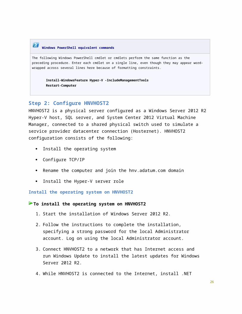
Windows PowerShell equivalent commands
The following Windows PowerShell cmdlet or cmdlets perform the same function as the preceding procedure. Enter each cmdlet on a single line, even though they may appear word-wrapped across several lines here because of formatting constraints.
Rename the interface connected to the shared physical switch to Hosternet prior to running the cmdlets below.
New-NetIPAddress -InterfaceAlias Hosternet -IPAddress 192.168.0.1 -AddressFamily IPv4 -PrefixLength 24Set-DnsClientServerAddress -InterfaceAlias Hosternet -ServerAddresses 192.168.0.1Set-DnsClient -InterfaceAlias Hosternet -ConnectionSpecificSuffix hnv.adatum.com Set-NetFirewallProfile -Profile Domain,Public,Private -Enabled False
Rename the computer to HNVHOST1
To rename the computer to HNVHOST1
1. In Server Manager, click Local Server in the console tree. Click the link next to Computer name in the Properties tile.
2. In the System Properties dialog box, click the Computer Name tab. On the Computer
14

Name tab, click Change.
3. In Computer Name, type HNVHOST1. Click OK.
4. When you are prompted that you must restart the computer, click OK.
5. On the System Properties dialog box, click Close.
6. When you are prompted to restart the computer, click Restart Now.
7. After the computer restarts, log on with the local administrator account.
Windows PowerShell equivalent commands
The following Windows PowerShell cmdlet or cmdlets perform the same function as the preceding procedure. Enter each cmdlet on a single line, even though they may appear word-wrapped across several lines here because of formatting constraints.
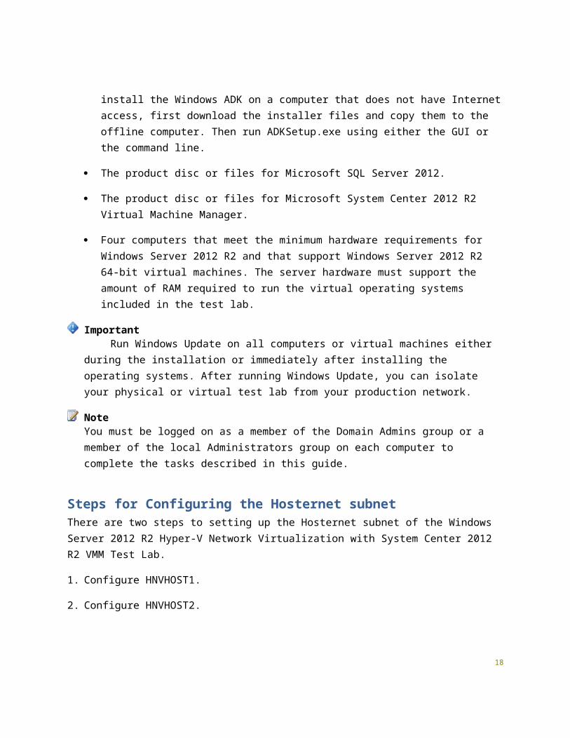
Rename-Computer -NewName HNVHOST1Restart-Computer
Configure HNVHOST1 as a domain controller and DNS serverNext, configure HNVHOST1 as a domain controller and DNS server for the hnv.adatum.com domain.
To configure HNVHOST1 as a domain controller and DNS server
1. Launch Server Manager.
2. On the Dashboard screen, under Configure this local server, click Add roles and features.
3. Click Next three times to get to the server role selection screen.
4. In the Select Server Roles dialog, select Active Directory Domain Services. Click Add Features when prompted, and then click Next.
5. In the Select features dialog, click Next.
6. In the Active Directory Domain Services dialog, click Next.
7. In the Confirm installation selections dialog, click Install. Wait for the installation to complete.
15

8. In the Installation Progress dialog, click the Promote this server to a domain controller link.
Note: If you close the "Installation Progress" dialog before it presents the promotion link, click the gray Tasks flag in the upper right section of Server Manager. When the installation is complete you will see the Promote this server to a Domain Controller link.
9. In the Deployment Configuration dialog, select Add a new forest. In the Root domain name field, type hnv.adatum.com. Click Next.
10. In the Domain Controller Options dialog, leave the default values, specify a strong DSRM password twice, and then click Next four times to accept default settings for DNS, NetBIOS, and directory paths.
11. In the Review Options dialog, review your selections and then click Next.
12. In the Prerequisites Check dialog, allow the validation to complete and verify that no errors are reported. Since this is the first DNS server deployment in the forest, you can safely ignore all warnings regarding DNS delegation. Click Install to start the domain controller promotion. Allow the installation to complete.
13. Allow the domain controller to restart. After the server restarts, logon using the HNV\Administrator credentials.
Windows PowerShell equivalent commands
The following Windows PowerShell cmdlet or cmdlets perform the same function as the preceding procedure. Enter each cmdlet on a single line, even though they may appear word-wrapped across several lines here because of formatting constraints.
Install-WindowsFeature AD-Domain-Services -IncludeManagementToolsInstall-ADDSForest -DomainName hnv.adatum.com
Create a user account in Active Directory on HNVHOST1Next, create a user account in Active Directory that will be used when logging in to HNV domain member computers.
16
To create a user account in Active Directory
1. From Server Manager, click the Tools menu item, and then click Active Directory Administrative Center.
2. In the console tree, click the arrow to expand HNV (local), and then double-click Users. This adds Users as a recent navigation link in the console tree.
3. In the Tasks pane, click New, and then click User.
4. In the Create User dialog, type User1 next to Full name and type User1 next to User SamAccountName logon: HNV\.
5. In Password, type the password that you want to use for this account, and in Confirm password, type the password again.
6. Under Password options, select Other password options, and select Password never expires.
7. Scroll down to access the Member of section of the Create User dialog, and click Add. Type Domain Admins; Enterprise Admins, and then click OK.
8. Click OK to close the Create User dialog.
9. Exit the Active Directory Administrative Center.
Windows PowerShell equivalent commands
The following Windows PowerShell cmdlet or cmdlets perform the same function as the preceding procedure. Enter each cmdlet on a single line, even though they may appear word-wrapped across several lines here because of formatting constraints.
Note that the first command results in a prompt to supply the user password.
New-ADUser -SamAccountName User1 -AccountPassword (read-host "Set user password" -assecurestring) -name "User1" -enabled $true -PasswordNeverExpires $true -ChangePasswordAtLogon $false
Add-ADPrincipalGroupMembership -Identity "CN=User1,CN=Users,DC=HNV,DC=adatum,DC=com" -MemberOf "CN=Enterprise Admins,CN=Users,DC=HNV,DC= adatum,DC=com","CN=Domain Admins,CN=Users,DC=HNV,DC= adatum,DC=com"
17

Install the Hyper-V server role on HNVHOST1Next, install the Hyper-V role on HNVHOST1, which will act as a host for virtual machines that are connected to the virtualized Contoso and Fabrikam tenant networks.
To install the Hyper-V server role
1. On the Server Manager Dashboard screen, under Configure this local server, click Add roles and features.
2. Click Next three times to get to the server role selection screen.
3. On the Select Server Roles page, select Hyper-V and click Add Features when prompted.
4. Click Next six times to accept the default settings for features and Hyper-V, and then click Install.
5. Verify that the installation was successful, and then click Close.
6. Restart the HNVHOST1 server after Hyper-V installation completes. After the computer restarts, click the Switch User arrow icon, then click Other User and log on to the HNV domain with the User1 account.
Windows PowerShell equivalent commands
The following Windows PowerShell cmdlet or cmdlets perform the same function as the preceding procedure. Enter each cmdlet on a single line, even though they may appear word-wrapped across several lines here because of formatting constraints.
Install-WindowsFeature Hyper-V -IncludeManagementToolsRestart-Computer
Step 2: Configure HNVHOST2HNVHOST2 is a physical server configured as a Windows Server 2012 R2 Hyper-V host, SQL server, and System Center 2012 Virtual Machine Manager, connected to a shared physical switch used to simulate a service provider datacenter connection (Hosternet). HNVHOST2 configuration consists of the following:
Install the operating system
Configure TCP/IP
18

Rename the computer and join the hnv.adatum.com domain
Install the Hyper-V server role
Install the operating system on HNVHOST2
To install the operating system on HNVHOST2
1. Start the installation of Windows Server 2012 R2.
2. Follow the instructions to complete the installation, specifying a strong password for the local Administrator account. Log on using the local Administrator account.
3. Connect HNVHOST2 to a network that has Internet access and run Windows Update to install the latest updates for Windows Server 2012 R2.
4. While HNVHOST2 is connected to the Internet, install .NET 3.5 by running the following command from an elevated Windows PowerShell prompt:
Install-WindowsFeature -Name NET-Framework-Core
Note: If HNVHOST2 does not have an Internet connection, you can install .NET framework from the Windows source files by using the following command:DISM /Online /Enable-Feature /FeatureName:NetFx3 /All /LimitAccess /Source:E:\sources\sxs
5. Connect HNVHOST2 to a shared physical switch to which HNVHOST1 is also connected. This connection will be used to simulate the Hosternet subnet.
Configure TCP/IP properties on HNVHOST2
To configure TCP/IP properties on HNVHOST2
1. In Server Manager, click Local Server in the console tree. Click the link next to Ethernet in the Properties tile.
2. Rename the network adapter connected to the Hosternet shared physical switch to Hosternet.
3. In the Network Connections window, right-click Hosternet, and then click Properties.
4. Click Internet Protocol Version 4 (TCP/IPv4), and then click Properties.
5. Select Use the following IP address. In IP address, type 192.168.0.2. In Subnet mask,
19

type 255.255.255.0. In Preferred DNS server, type 192.168.0.1.
6. Click Advanced, and then click the DNS tab.
7. In DNS suffix for this connection, type hnv.adatum.com, and then click OK.
8. Click OK three times to close the Hosternet Properties dialog box.
9. Close the Network Connections window.
10. From the Tools menu in Server Manager, click Windows PowerShell.
11. To disable the Windows Firewall on HNVHOST2, type the following command and press ENTER.
Set-NetFirewallProfile -Profile Domain,Public,Private -Enabled False
Windows PowerShell equivalent commands
The following Windows PowerShell cmdlet or cmdlets perform the same function as the preceding procedure. Enter each cmdlet on a single line, even though they may appear word-wrapped across several lines here because of formatting constraints.
Rename the interface connected to the shared physical switch to Hosternet prior to running the cmdlets below.
New-NetIPAddress -InterfaceAlias Hosternet -IPAddress 192.168.0.2 -AddressFamily IPv4 -PrefixLength 24Set-DnsClientServerAddress -InterfaceAlias Hosternet -ServerAddresses 192.168.0.1Set-DnsClient -InterfaceAlias Hosternet -ConnectionSpecificSuffix hnv.adatum.com Set-NetFirewallProfile -Profile Domain,Public,Private -Enabled False
Rename the computer to HNVHOST2 and join the hnv.adatum.com domain
To rename the computer to HNVHOST2 and join the hnv.adatum.com domain
1. In Server Manager, click Local Server in the console tree. Click the link next to Computer name in the Properties tile.
2. In the System Properties dialog box, click the Computer Name tab. On the Computer Name tab, click Change.
3. In Computer Name, type HNVHOST2. Under Member of, click Domain, and then type
20
hnv.adatum.com.
4. Click OK.
5. When you are prompted for a user name and password, type User1 and its password, and then click OK.
6. When you see a dialog box welcoming you to the hnv.adatum.com domain, click OK.
7. When you are prompted that you must restart the computer, click OK.
8. On the System Properties dialog box, click Close.
9. When you are prompted to restart the computer, click Restart Now.
10. After the computer restarts, click the Switch User arrow icon, then click Other User and log on to the HNV domain with the User1 account.
Windows PowerShell equivalent commands
The following Windows PowerShell cmdlet or cmdlets perform the same function as the preceding procedure. Enter each cmdlet on a single line, even though they may appear word-wrapped across several lines here because of formatting constraints.
Supply the credentials for the User1 domain account when prompted after running the first command.
Add-Computer -NewName HNVHOST2 -DomainName hnv.adatum.comRestart-Computer
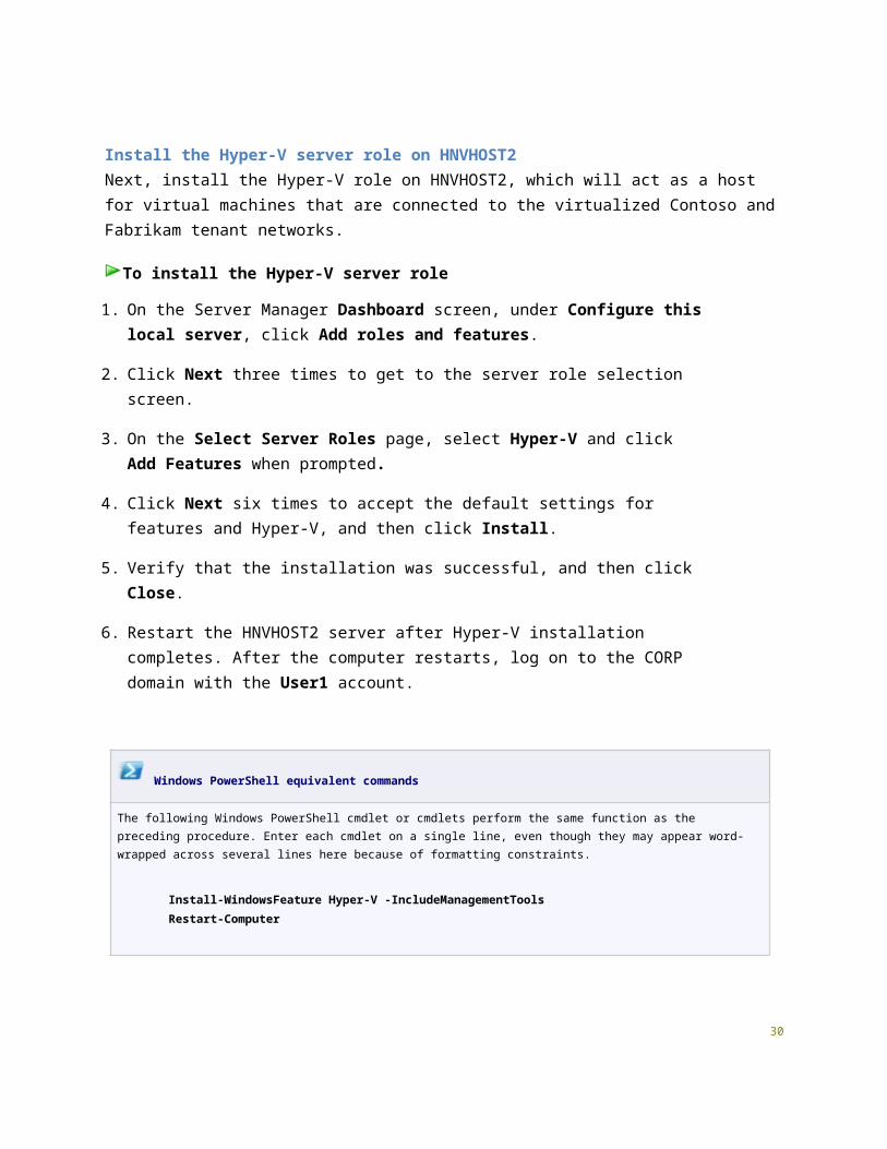
Install the Hyper-V server role on HNVHOST2Next, install the Hyper-V role on HNVHOST2, which will act as a host for virtual machines that are connected to the virtualized Contoso and Fabrikam tenant networks.
To install the Hyper-V server role
1. On the Server Manager Dashboard screen, under Configure this local server, click Add roles and features.
2. Click Next three times to get to the server role selection screen.
3. On the Select Server Roles page, select Hyper-V and click Add Features when
21

prompted.
4. Click Next six times to accept the default settings for features and Hyper-V, and then click Install.
5. Verify that the installation was successful, and then click Close.
6. Restart the HNVHOST2 server after Hyper-V installation completes. After the computer restarts, log on to the CORP domain with the User1 account.
Windows PowerShell equivalent commands
The following Windows PowerShell cmdlet or cmdlets perform the same function as the preceding procedure. Enter each cmdlet on a single line, even though they may appear word-wrapped across several lines here because of formatting constraints.
Install-WindowsFeature Hyper-V -IncludeManagementToolsRestart-Computer
Steps for Configuring the Internet SubnetThere are four steps to setting up the Internet subnet of the Windows Server 2012 R2 Hyper-V Network Virtualization with System Center 2012 R2 VMM Test Lab.
1. Configure HNVHOST4.
2. Configure INET1.
3. Configure HNVHOST3.
Step 1: Configure HNVHOST4HNVHOST4 is a physical server configured as a Windows Server 2012 R2 Hyper-V host connected to a physical switch used to simulate an Internet connection. Virtual machines running on HNVHOST4 are used to simulate customer on-premises resources for the Contoso and Fabrikam corporate networks. HNVHOST4 configuration consists of the following:
Install the operating system
Configure TCP/IP
Rename the computer
22

Install the Hyper-V server role
Create a Hyper-V external virtual switch to simulate a connection to the Internet
Create two Hyper-V internal virtual switches to simulate the Contoso and Fabrikam corporate networks
Create virtual machines on HNVHOST4 for INET1, Contoso DC1, Contoso APP1, Contoso EDGE1, Fabrikam DC1, Fabrikam APP1, and Fabrikam EDGE1
Install the operating system on HNVHOST4
To install the operating system on HNVHOST4
1. Start the installation of Windows Server 2012 R2.
2. Follow the instructions to complete the installation, specifying a strong password for the local Administrator account. Log on using the local Administrator account.
3. Connect HNVHOST4 to a network that has Internet access and run Windows Update to install the latest updates for Windows Server 2012 R2.
4. Connect HNVHOST4 a shared physical switch to which HNVHOST3 is also connected. This connection will be used to simulate the Internet subnet.
Configure TCP/IP properties on HNVHOST4
To configure TCP/IP properties on HNVHOST4
1. In Server Manager, click Local Server in the console tree. Click the link next to Ethernet in the Properties tile.
2. Rename the adapter that is connected to the shared physical switch to Internet.
3. In the Network Connections window, right-click Internet, and then click Properties.
4. Click Internet Protocol Version 4 (TCP/IPv4), and then click Properties.
5. Select Use the following IP address. In IP address, type 131.107.0.40. In Subnet mask, type 255.255.255.0. In Preferred DNS server, type 131.107.0.1.
6. Click Advanced, and then click the DNS tab.
7. In DNS suffix for this connection, type isp.example.com, and then click OK.
23

8. Click OK twice to close the Internet Properties dialog box.
9. Close the Network Connections window.
10. From the Tools menu in Server Manager, click Windows PowerShell.
11. To configure the firewall to allow ICMPv4 ping packets, type the following commands and press ENTER after each command.
New-NetFirewallRule –DisplayName “Allow ICMPv4-In” –Protocol ICMPv4
New-NetFirewallRule –DisplayName “Allow ICMPv4-Out” –Protocol ICMPv4 –Direction Outbound
12. Close the Windows PowerShell window.
Windows PowerShell equivalent commands
The following Windows PowerShell cmdlet or cmdlets perform the same function as the preceding procedure. Enter each cmdlet on a single line, even though they may appear word-wrapped across several lines here because of formatting constraints.
Note: Prior to running the following commands, name the network connection attached to the shared physical switch Internet.
New-NetIPAddress -InterfaceAlias Internet -IPAddress 131.107.0.40 -AddressFamily IPv4 -PrefixLength 24Set-DnsClientServerAddress -InterfaceAlias Internet -ServerAddresses 131.107.0.1Set-DnsClient -InterfaceAlias Internet -ConnectionSpecificSuffix isp.example.com New-NetFirewallRule –DisplayName “Allow ICMPv4-In” –Protocol ICMPv4New-NetFirewallRule –DisplayName “Allow ICMPv4-Out” –Protocol ICMPv4 –Direction Outbound
Rename the computer to HNVHOST4
To rename the computer to HNVHOST4
1. In Server Manager, click Local Server in the console tree. Click the link next to Computer name in the Properties tile.
2. In the System Properties dialog box, click the Computer Name tab. On the Computer Name tab, click Change.
24
3. In Computer Name, type HNVHOST4. Click OK.
4. When you are prompted that you must restart the computer, click OK.
5. On the System Properties dialog box, click Close.
6. When you are prompted to restart the computer, click Restart Now.
7. After the computer restarts, log on with the local administrator account.
Windows PowerShell equivalent commands
The following Windows PowerShell cmdlet or cmdlets perform the same function as the preceding procedure. Enter each cmdlet on a single line, even though they may appear word-wrapped across several lines here because of formatting constraints.
Rename-Computer -NewName HNVHOST4Restart-Computer
Install the Hyper-V server role on HNVHOST4Next, install the Hyper-V role on HNVHOST4, which will act as a host for virtual machines that are connected to the Contoso Corpnet, Fabrikam Corpnet, and Internet subnets.
To install the Hyper-V server role
1. On the Server Manager Dashboard screen, under Configure this local server, click Add roles and features.
2. Click Next three times to get to the server role selection screen.
3. On the Select Server Roles page, select Hyper-V and click Add Features when prompted.
4. Click Next six times to accept the default settings for features and Hyper-V, and then click Install.
5. Verify that the installation was successful, and then click Close.
25

Windows PowerShell equivalent commands
The following Windows PowerShell cmdlet or cmdlets perform the same function as the preceding procedure. Enter each cmdlet on a single line, even though they may appear word-wrapped across several lines here because of formatting constraints.
Install-WindowsFeature Hyper-V -IncludeManagementToolsRestart-Computer
Create virtual switches on HNVHOST4
To create Internet, Contoso Corpnet, and Fabrikam Corpnet virtual switches on HNVHOST4
1. From Server Manager, click the Tools menu item, and then click Hyper-V Manager.
2. In Hyper-V Manager console, select HNVHOST4, and then click Virtual Switch Manager in the Actions pane.
3. Verify that External is selected, and then click Create Virtual Switch.
4. Under Name, type Internet. Under External network, select the adapter connected to the Internet physical switch. Select the checkbox for Allow management operating system to share this network adapter. Click Apply.
5. In the Virtual Switch Manager window, click New virtual network switch. Under What type of virtual switch do you want to create?, select Private, and then click Create Virtual Switch.
6. Under Name, type Contoso_Corpnet, and then click Apply.
7. In the Virtual Switch Manager window, click New virtual network switch. Under What type of virtual switch do you want to create?, select Private, and then click Create Virtual Switch.
8. Under Name, type Fabrikam_Corpnet, and then click Apply.
9. Click OK to close Virtual Switch Manager.
Windows PowerShell equivalent commands
The following Windows PowerShell cmdlet or cmdlets perform the same function as the preceding procedure. 26

Enter each cmdlet on a single line, even though they may appear word-wrapped across several lines here because of formatting constraints.
New-VmSwitch -Name Internet -AllowManagementOS 1 -NetAdapterName InternetNew-VmSwitch -Name Contoso_Corpnet -SwitchType PrivateNew-VmSwitch -Name Fabrikam_Corpnet -SwitchType Private
Create virtual machines on HNVHOST4
To create Internet, Contoso Corpnet, and Fabrikam Corpnet virtual machines on HNVHOST4
1. In Hyper-V Manager console Actions pane, point to New, and then click Virtual Machine.
2. The New Virtual Machine Wizard opens. Click Next.
3. Name the new virtual machine INET1. Click Next.
4. Select Generation 1 as the virtual machine generation, and then click Next.
5. Assign memory to allocate to the new VM, and then click Next.
6. On the Configure Networking page select a connection to the Internet virtual switch. Click Next.
7. On the Connect Virtual Hard Disk page, select an option to create a new virtual hard disk or specify a path to an existing virtual hard disk for INET1. Click Next.
8. On the Installation Options page, select the appropriate options to access the operating system setup media. Click Next.
9. On the Summary page, click Finish.
10. Repeat the previous steps to create additional virtual machines as listed in the following table:
Virtual Machine Name Network Connections
INET1 One virtual adapter connected to the Internet virtual switch
Contoso_DC1 One virtual adapter connected to the Contoso_Corpnet virtual switch
Contoso_APP1 One virtual adapter connected to the Contoso_Corpnet virtual 27

switch
Contoso_EDGE1 Two virtual adapters, one connected to the Contoso_Corpnet virtual switch, one connected to the Internet virtual switch
Fabrikam_DC1 One virtual adapter connected to the Fabrikam_Corpnet virtual switch
Fabrikam_APP1 One virtual adapter connected to the Fabrikam_Corpnet virtual switch
Fabrikam_EDGE1 Two virtual adapters, one connected to the Fabrikam_Corpnet virtual switch, one connected to the Internet virtual switch
Step 2: Configure INET1
Note: The Windows Server 2012 R2 Hyper-V Network Virtualization with System Center 2012 VMM test lab can be built using the "Steps for Configuring the Corpnet Subnet" and "Steps for Configuring the Internet Subnet" sections of the Test Lab Guide: Windows Server 2012 R2 Base Configuration as its base. If you have already built the Windows Server 2012 R2 Base Configuration using virtual machines, you can use the INET1 computer for the Internet subnet in place of the instructions below.
INET1 configuration consists of the following:
Install the operating system
Configure TCP/IP
Rename the computer
Install the Web Server (IIS) and DNS server roles
Create DNS records
Install DHCP
Configure the NCSI web site
28
Install the operating system on INET1
To install the operating system on INET1
1. Start the installation of Windows Server 2012 R2.
2. Follow the instructions to complete the installation, specifying a strong password for the local Administrator account. Log on using the local Administrator account.
3. Connect INET1 to a network that has Internet access and run Windows Update to install the latest updates for Windows Server 2012 R2.
4. Connect the INET1 virtual machine to the Internet virtual switch on HNVHOST4.
Configure TCP/IP properties on INET1
To configure TCP/IP properties on INET1
1. In Server Manager, click Local Server in the console tree. Click the link next to Ethernet in the Properties tile.
2. In the Network Connections window, right-click Ethernet, and then click Properties.
3. Click Internet Protocol Version 4 (TCP/IPv4), and then click Properties.
4. Select Use the following IP address. In IP address, type 131.107.0.1. In Subnet mask, type 255.255.255.0. In Preferred DNS server, type 127.0.0.1.
5. Click Advanced, and then click the DNS tab.
6. In DNS suffix for this connection, type isp.example.com, and then click OK.
7. Click OK twice to close the Ethernet Properties dialog box.
8. Close the Network Connections window.
9. From the Tools menu in Server Manager, click Windows PowerShell.
10. To configure the firewall to allow ICMPv4 ping packets, type the following commands and press ENTER after each command.
New-NetFirewallRule –DisplayName “Allow ICMPv4-In” –Protocol ICMPv4
New-NetFirewallRule –DisplayName “Allow ICMPv4-Out” –Protocol ICMPv4 –
29

Direction Outbound
11. Close the Windows PowerShell window.
Windows PowerShell equivalent commands
The following Windows PowerShell cmdlet or cmdlets perform the same function as the preceding procedure. Enter each cmdlet on a single line, even though they may appear word-wrapped across several lines here because of formatting constraints.
Note that the "Ethernet" interface name may be different on your computer. Use ipconfig /all to list out the interfaces.
New-NetIPAddress -InterfaceAlias Ethernet -IPAddress 131.107.0.1 -AddressFamily IPv4 -PrefixLength 24Set-DnsClientServerAddress -InterfaceAlias Ethernet -ServerAddresses 127.0.0.1Set-DnsClient -InterfaceAlias Ethernet -ConnectionSpecificSuffix isp.example.com New-NetFirewallRule –DisplayName “Allow ICMPv4-In” –Protocol ICMPv4New-NetFirewallRule –DisplayName “Allow ICMPv4-Out” –Protocol ICMPv4 –Direction Outbound
Rename the computer to INET1
To rename the computer to INET1
1. In Server Manager, click Local Server in the console tree. Click the link next to Computer name in the Properties tile.
2. In the System Properties dialog box, click the Computer Name tab. On the Computer Name tab, click Change.
3. In Computer Name, type INET1. Click OK.
4. When you are prompted that you must restart the computer, click OK.
5. On the System Properties dialog box, click Close.
6. When you are prompted to restart the computer, click Restart Now.
7. After the computer restarts, log on with the local administrator account.
30

Windows PowerShell equivalent commands
The following Windows PowerShell cmdlet or cmdlets perform the same function as the preceding procedure. Enter each cmdlet on a single line, even though they may appear word-wrapped across several lines here because of formatting constraints.
Rename-Computer -NewName INET1Restart-Computer
Install the DNS Server and Web Server (IIS) server roles on INET1Next, install role services for INET1, which will act as an Internet web and DNS server for computers that are connected to the Internet subnet.
To install the IIS and DNS server roles
1. On the Server Manager Dashboard screen, under Configure this local server, click Add roles and features.
2. Click Next three times to get to the server role selection screen.
3. On the Select Server Roles page, select DNS Server and click Add Features when prompted.
4. Select Web Server (IIS) and then click Next.
5. Click Next four times to accept the default DNS server and web server settings, and then click Install.
6. Verify that the installations were successful, and then click Close.
Windows PowerShell equivalent commands
The following Windows PowerShell cmdlet or cmdlets perform the same function as the preceding procedure. Enter each cmdlet on a single line, even though they may appear word-wrapped across several lines here because of formatting constraints.
Install-WindowsFeature DNS -IncludeManagementToolsInstall-WindowsFeature Web-WebServer -IncludeManagementTools
31

Create DNS records on INET1Next, create DNS records for the INET1 and EDGE1 IPv4 addresses on the Internet subnet and for the Network Connectivity Status Indicator (NCSI).
To create A records
1. From Server Manager, click the Tools menu item, and then click DNS.
2. In the console tree of DNS Manager, expand INET1, and click Forward Lookup Zones.
3. Right-click Forward Lookup Zones, click New Zone, and then click Next.
4. On the Zone Type page, click Next.
5. On the Zone Name page, type isp.example.com, and then click Next.
6. Click Next twice to accept defaults for zone file and dynamic update, and then click Finish.
7. In the console tree, expand Forward Lookup Zones, right click isp.example.com, and then click New Host (A or AAAA).
8. In Name, type INET1. In IP address, type 131.107.0.1. Click Add Host.
9. Click OK, and then click Done.
10. In the console tree, right-click Forward Lookup Zones, click New Zone, and then click Next.
11. On the Zone Type page, click Next.
12. On the Zone Name page, type contoso.com, and then click Next.
13. Click Next twice to accept defaults for zone file and dynamic update, and then click Finish.
14. In the console tree, right click contoso.com, and then click New Host (A or AAAA).
15. In Name, type EDGE1. In IP address, type 131.107.0.2.
16. Click Add Host. Click OK.
17. In the console tree, right-click Forward Lookup Zones, click New Zone, and then click Next.
18. On the Zone Type page, click Next.
19. On the Zone Name page, type msftncsi.com, and then click Next.
20. Click Next twice to accept defaults for zone file and dynamic update, and then click Finish.
32

21. In the console tree, right click msftncsi.com, and then click New Host (A or AAAA).
22. In Name, type www. In IP address, type 131.107.0.1.
23. Click Add Host. Click OK.
24. In Name, type dns. In IP address, type 131.107.255.255. Click Add Host. Click OK. Click Done.
24. Close the DNS Manager console.
Windows PowerShell equivalent commands
The following Windows PowerShell cmdlet or cmdlets perform the same function as the preceding procedure. Enter each cmdlet on a single line, even though they may appear word-wrapped across several lines here because of formatting constraints.
Add-DnsServerPrimaryZone -Name isp.example.com -ZoneFile isp.example.com.dnsAdd-DnsServerResourceRecordA -ZoneName isp.example.com -Name inet1 -IPv4Address 131.107.0.1Add-DnsServerPrimaryZone -Name contoso.com -ZoneFile contoso.com.dnsAdd-DnsServerResourceRecordA -ZoneName contoso.com -Name edge1 -IPv4Address 131.107.0.2Add-DnsServerPrimaryZone -Name msftncsi.com -ZoneFile msftncsi.com.dnsAdd-DnsServerResourceRecordA -ZoneName msftncsi.com -Name www -IPv4Address 131.107.0.1Add-DnsServerResourceRecordA -ZoneName msftncsi.com -Name dns -IPv4Address 131.107.255.255
Install and configure DHCP on INET1Next, configure INET1 as a DHCP server so that DHCP clients can automatically configure themselves when connecting to the Internet subnet.
To install and configure the DHCP server role on INET1
1. On the Server Manager Dashboard screen, under Configure this local server, click Add roles and features.
2. Click Next three times to get to the server role selection screen.
3. In the Select Server Roles dialog, select DHCP Server, click Add Features when prompted, and then click Next.
4. In the Select features dialog, click Next.
33

5. Click Next on the Introduction screen, and then click Install.
6. Allow the installation to complete, and then in the Installation progress window, click the link for Complete DHCP configuration.
7. In the DHCP Post-Install configuration wizard, click Commit, and then click Close.
8. In the Installation progress window, click Close.
9. From the Tools menu in Server Manager, click DHCP.
10. In the DHCP console tree, expand INET1. Right-click IPv4, and click New Scope.
11. Click Next in the New Scope Wizard.
12. Type Internet for scope name, and then click Next.
13. Next to Start IP Address, type 131.107.0.100, next to End IP Address, type 131.107.0.150, and next to Subnet Mask, type 255.255.255.0.
14. Click Next four times to accept default settings for exclusions, delay and lease duration.
15. On the Router (Default Gateway) dialog, type 131.107.0.1. Click Add, and then click Next.
16. On the Domain Name and DNS Servers page, next to Parent domain, type isp.example.com. Under IP address, type 131.107.0.1. Click Add, and then click Next.
17. On the WINS Servers page, click Next.
18. On the Activate Scope page, click Next, and then click Finish.
19. Close the DHCP Manager console.
Windows PowerShell equivalent commands
The following Windows PowerShell cmdlet or cmdlets perform the same function as the preceding procedure. Enter each cmdlet on a single line, even though they may appear word-wrapped across several lines here because of formatting constraints.
Install-WindowsFeature DHCP -IncludeManagementToolsAdd-DhcpServerv4Scope -name "Internet" -StartRange 131.107.0.100 -EndRange 131.107.0.150 -SubnetMask 255.255.255.0Set-DhcpServerv4OptionValue -DnsDomain isp.example.com -DnsServer 131.107.0.1 -Router 131.107.0.1
34

Configure the NCSI web site on INET1Windows clients attempt to connect to the URL http://www.msftncsi.com/ncsi.txt and resolve the name dns.msftncsi.com to determine if they have Internet connectivity. In the following procedure, you create the ncsi.txt file and place it in the WWWROOT directory on INET1.
To configure the NCSI web site on INET1
1. On INET1, launch File Explorer, and then navigate to C:\inetpub\wwwroot.
2. In the details pane, right click an empty area, point to New, and then click Text Document.
3. Rename the document to ncsi.
4. Double-click on ncsi.
5. In the Notepad window, type Microsoft NCSI and do not press ENTER to add a new line.
6. Click File, and then click Exit. In the Notepad dialog box, click Save.
7. Close the Windows Explorer window.
Windows PowerShell equivalent commands
The following PowerShell commands perform the same steps to write the Ncsi.txt file without a new line after the "Microsoft NCSI" string:
$filename = "C:\inetpub\wwwroot\ncsi.txt"$text = "Microsoft NCSI"[System.IO.File]::WriteAllText($fileName, $text)
Step 3: Configure HNVHOST3HNVHOST3 is a physical server configured to host Hyper-V Network Virtualization Gateway virtual machines, with two network adapters. One adapter is connected to a physical switch used to simulate an Internet connection, and the second adapter is connected to a physical switch used to simulate a service provider datacenter connection (Hosternet). HNVHOST3 configuration consists of the following:
Install the operating system35

Configure network connections
Rename the computer and join the hnv.adatum.com domain
Install the Hyper-V server role
Install the operating system on HNVHOST3
To install the operating system on HNVHOST3
1. Start the installation of Windows Server 2012 R2.
2. Follow the instructions to complete the installation, specifying a strong password for the local Administrator account. Log on using the local Administrator account.
3. Connect HNVHOST3 to a network that has Internet access and run Windows Update to install the latest updates for Windows Server 2012 R2.
4. Connect one adapter on HNVHOST3 a shared physical switch to which HNVHOST2 is also connected. This connection will be used to simulate the Hosternet subnet.
5. Connect one adapter on HNVHOST3 a shared physical switch to which HNVHOST4 is also connected. This connection will be used to simulate the Internet subnet.
Configure network connections on HNVHOST3
To configure network connection properties on HNVHOST3
1.In Server Manager, click Local Server in the console tree. Click the link next to Ethernet in the Properties tile.
2.In Network Connections, right-click the network connection that is connected to the shared physical switch to which HNVHOST4 is also connected, and then click Rename.
3.Type Internet, and then press ENTER.
4.In the Network Connections window, right-click Internet, and then click Properties.
5.Click Internet Protocol Version 4 (TCP/IPv4), and then click Properties.
6.Select Use the following IP address. In IP address, type 131.107.0.30. In Subnet mask, type 255.255.255.0. In Preferred DNS server, type 131.107.0.1.
7.Click Advanced, and then click the DNS tab.
36

8.In DNS suffix for this connection, type isp.example.com, and then click OK.
9.Click OK twice to close the Internet Properties dialog box.
10. In Network Connections, right-click the network connection that is connected to the shared physical switch to which HNVHOST2 is also connected, and then click Rename.
11. Type Hosternet, and then press ENTER.
12. In the Network Connections window, right-click Hosternet, and then click Properties.
13. Click Internet Protocol Version 4 (TCP/IPv4), and then click Properties.
14. Select Use the following IP address. In IP address, type 192.168.0.3. In Subnet mask, type 255.255.255.0. In Preferred DNS server, type 192.168.0.1.
15. Click Advanced, and then click the DNS tab.
16. In DNS suffix for this connection, type hnv.adatum.com, and then click OK.
17. Click OK three times to close the Hosternet Properties dialog box.
18. Close the Network Connections window.
19. From the Tools menu in Server Manager, click Windows PowerShell.
20. To disable the Windows Firewall on HNVHOST3, type the following command and press ENTER.
Set-NetFirewallProfile -Profile Domain,Public,Private -Enabled False
21. Type ping 131.107.0.1 and press ENTER to verify connectivity to INET1 from HNVHOST3.
22. Type ping 192.168.0.2 and press ENTER to verify connectivity to HNVHOST2 from HNVHOST3.
Windows PowerShell equivalent commands
The following Windows PowerShell cmdlet or cmdlets perform the same function as the preceding procedure. Enter each cmdlet on a single line, even though they may appear word-wrapped across several lines here because of formatting constraints.
Ensure that the interfaces have been renamed to Hosternet and Internet prior to running the following 37

commands.
New-NetIPAddress -InterfaceAlias Internet -IPAddress 131.107.0.30 -AddressFamily IPv4 -PrefixLength 24Set-DnsClientServerAddress -InterfaceAlias Internet -ServerAddresses 131.107.0.1Set-DnsClient -InterfaceAlias Internet -ConnectionSpecificSuffix isp.example.com New-NetIPAddress -InterfaceAlias Hosternet -IPAddress 192.168.0.3 -AddressFamily IPv4 -PrefixLength 24Set-DnsClientServerAddress -InterfaceAlias Hosternet -ServerAddresses 192.168.0.1Set-DnsClient -InterfaceAlias Hosternet -ConnectionSpecificSuffix hnv.adatum.com Set-NetFirewallProfile -Profile Domain,Public,Private -Enabled False
Rename the computer to HNVHOST3 and join the hnv.adatum.com domain
To rename the computer to HNVHOST3 and join the hnv.adatum.com domain
1. In Server Manager, click Local Server in the console tree. Click the link next to Computer name in the Properties tile.
2. In the System Properties dialog box, click the Computer Name tab. On the Computer Name tab, click Change.
3. In Computer Name, type HNVHOST3. Under Member of, click Domain, and then type hnv.adatum.com.
4. Click OK.
5. When you are prompted for a user name and password, type User1 and its password, and then click OK.
6. When you see a dialog box welcoming you to the hnv.adatum.com domain, click OK.
7. When you are prompted that you must restart the computer, click OK.
8. On the System Properties dialog box, click Close.
9. When you are prompted to restart the computer, click Restart Now.
10. After the computer restarts, click the Switch User arrow icon, then click Other User and log on to the HNV domain with the User1 account.
Windows PowerShell equivalent commands
38

The following Windows PowerShell cmdlet or cmdlets perform the same function as the preceding procedure. Enter each cmdlet on a single line, even though they may appear word-wrapped across several lines here because of formatting constraints.
Add-Computer -NewName HNVHOST3 -DomainName hnv.adatum.comRestart-Computer
Install the Hyper-V server role on HNVHOST3Next, install the Hyper-V role on HNVHOST3, which will act as a host for a gateway virtual machine that is connected to the Internet for site-to-site routing to the Contoso Corpnet and Fabrikam Corpnet subnets, and a second gateway virtual machine that provides direct routing to the service provider network.
To install the Hyper-V server role
1. On the Server Manager Dashboard screen, under Configure this local server, click Add roles and features.
2. Click Next three times to get to the server role selection screen.
3. On the Select Server Roles page, select Hyper-V and click Add Features when prompted.
4. Click Next six times to accept the default settings for features and Hyper-V, and then click Install.
5. Verify that the installation was successful, and then click Close.
6. Restart the HNVHOST3 server after Hyper-V installation completes.
Windows PowerShell equivalent commands
The following Windows PowerShell cmdlet or cmdlets perform the same function as the preceding procedure. Enter each cmdlet on a single line, even though they may appear word-wrapped across several lines here because of formatting constraints.
Install-WindowsFeature Hyper-V -IncludeManagementToolsRestart-Computer
39

Steps for Configuring the Contoso Corpnet SubnetThe Contoso Corpnet subnet is used to simulate a customer on-premises network infrastructure. A cross-premises VPN connection will be established later in order to access the cloud service provider network. There are four steps to setting up the Contoso Corpnet subnet on HNVHOST4.
1. Configure DC1.
2. Configure APP1.
3. Configure EDGE1.
4. Test access to resources on APP1.
The following sections provide details about how to perform these steps.
Note: The Windows Server 2012 R2 Hyper-V Network Virtualization with System Center 2012 VMM test lab can be built using the "Steps for Configuring the Corpnet Subnet" and "Steps for Configuring the Internet Subnet" sections of the Test Lab Guide: Windows Server 2012 R2 Base Configuration as its base. If you have already built the Windows Server 2012 R2 Base Configuration using virtual machines, you can use the DC1, EDGE1, and APP1 computers for the Contoso Corpnet subnet in place of the instructions below.
Step 1: Configure DC1DC1 is a virtual machine running on the HNVHOST4 server. DC1 provides the following services:
A domain controller for the corp.contoso.com Active Directory Domain Services (AD DS) domain
A DNS server for the corp.contoso.com DNS domain
A DHCP server for the Corpnet subnet
DC1 configuration consists of the following:
Install the operating system
Configure TCP/IP
Install Active Directory and DNS
Install DHCP
Create a user account in Active Directory
40

Install the operating system on DC1First, install Windows Server 2012 R2 as a standalone server.
To install the operating system on DC1
1. Start the installation of Windows Server 2012 R2.
2. Follow the instructions to complete the installation, specifying Windows Server 2012 R2 Datacenter (Server with a GUI) and a strong password for the local Administrator account. Log on using the local Administrator account.
3. Connect DC1 to a network that has Internet access and run Windows Update to install the latest updates for Windows Server 2012 R2.
4. Connect DC1 to the Contoso_Corpnet virtual switch on HNVHOST4.
Configure TCP/IP properties on DC1Next, configure the TCP/IP protocol with a static IP address of 10.0.0.1 and the subnet mask of 255.255.255.0.
To configure TCP/IP on DC1
1. In Server Manager, click Local Server in the console tree. Click the link next to Ethernet.
Note The link may not immediately appear. Wait for the network interfaces to be enumerated.
2. In Network Connections, right-click Ethernet, and then click Properties. Note that the "Ethernet" interface name may be different on your computer.
3. Click Internet Protocol Version 4 (TCP/IPv4), and then click Properties.
4. Select Use the following IP address. In IP address, type 10.0.0.1. In Subnet mask, type 255.255.255.0. In Default gateway, type 10.0.0.2. Select Use the following DNS server addresses. In Preferred DNS server, type 127.0.0.1.
5. Click OK and then close the Ethernet Properties dialog.
6. Close the Network Connections window.
7. From the Tools menu in Server Manager, click Windows PowerShell.
8. To configure the firewall to allow ICMPv4 ping packets, type the following commands and
41

press ENTER after each command.
New-NetFirewallRule –DisplayName “Allow ICMPv4-In” –Protocol ICMPv4
New-NetFirewallRule –DisplayName “Allow ICMPv4-Out” –Protocol ICMPv4 –Direction Outbound
9. Close the Windows PowerShell window.
10. In Server Manager, click Local Server in the console tree. Click the link next to Computer name in the Properties tile.
11. On the Computer Name tab of the System Properties dialog, click Change.
12. In Computer name, type DC1, click OK twice, and then click Close. When you are prompted to restart the computer, click Restart Now.
13. After restarting, login using the local Administrator account.
Windows PowerShell equivalent commands
The following Windows PowerShell cmdlet or cmdlets perform the same function as the preceding procedure. Enter each cmdlet on a single line, even though they may appear word-wrapped across several lines here because of formatting constraints.
Note that the "Ethernet" interface name may be different on your computer. Use the ipconfig /all command to list all the interfaces.
New-NetIPAddress -InterfaceAlias Ethernet -IPAddress 10.0.0.1 -AddressFamily IPv4 -PrefixLength 24 -DefaultGateway 10.0.0.2Set-DnsClientServerAddress -InterfaceAlias Ethernet -ServerAddresses 127.0.0.1New-NetFirewallRule –DisplayName “Allow ICMPv4-In” –Protocol ICMPv4New-NetFirewallRule –DisplayName “Allow ICMPv4-Out” –Protocol ICMPv4 –Direction OutboundRename-Computer DC1Restart-Computer
Configure DC1 as a domain controller and DNS serverNext, configure DC1 as a domain controller and DNS server for the corp.contoso.com domain.
42

To configure DC1 as a domain controller and DNS server
1. Launch Server Manager.
2. On the Dashboard screen, under Configure this local server, click Add roles and features.
3. Click Next three times to get to the server role selection screen.
4. In the Select Server Roles dialog, select Active Directory Domain Services. Click Add Features when prompted, and then click Next.
5. In the Select features dialog, click Next.
6. In the Active Directory Domain Services dialog, click Next.
7. In the Confirm installation selections dialog, click Install. Wait for the installation to complete.
8. In the Installation Progress dialog, click the Promote this server to a domain controller link.
Note: If you close the "Installation Progress" dialog before it presents the promotion link, click the gray Tasks flag in the upper right section of Server Manager. When the installation is complete you will see the Promote this server to a Domain Controller link.
9. In the Deployment Configuration dialog, select Add a new forest. In the Root domain name field, type corp.contoso.com. Click Next.
10. In the Domain Controller Options dialog, leave the default values, specify a strong DSRM password twice, and then click Next four times to accept default settings for DNS, NetBIOS, and directory paths.
11. In the Review Options dialog, review your selections and then click Next.
Note: You can also click the View script button to review and save the PowerShell commands that Server Manager will run during DC Promotion.
12. In the Prerequisites Check dialog, allow the validation to complete and verify that no errors are reported. Since this is the first DNS server deployment in the forest, you can safely ignore all warnings regarding DNS delegation. Click Install to start the domain controller promotion. Allow the installation to complete.
43

13. Allow the domain controller to restart. After the server restarts, logon using the CORP\Administrator credentials.
Windows PowerShell equivalent commands
The following Windows PowerShell cmdlet or cmdlets perform the same function as the preceding procedure. Enter each cmdlet on a single line, even though they may appear word-wrapped across several lines here because of formatting constraints.
Install-WindowsFeature AD-Domain-Services -IncludeManagementToolsInstall-ADDSForest -DomainName corp.contoso.com
Install and configure DHCP on DC1Next, configure DC1 as a DHCP server so that remote computers can automatically obtain an IP address when establishing site-to-site VPN connections.
To install and configure the DHCP server role on DC1
1. In the Dashboard console of Server Manager, under Configure this local server, click Add roles and features.
2. Click Next three times to get to the server role selection screen.
3. In the Select server roles dialog, select DHCP Server, click Add Features when prompted, and then click Next.
4. In the Select features dialog, click Next.
5. Click Next on the DHCP Server screen, and then click Install.
6. Allow the installation to complete, and then in the Results window, click the link for Complete DHCP configuration.
7. In the DHCP Post-Install configuration wizard, click Next, and then click Commit.
8. On the Summary page, click Close.
9. In the Add Roles and Features Wizard, click Close.
10. From the Tools menu in Server Manager, click DHCP.
11. In the DHCP console tree, expand dc1.corp.contoso.com, and click IPv4. Right-click IPv4, 44

and click New Scope.
12. Click Next in the New Scope Wizard.
13. Type Corpnet for scope name, and then click Next.
14. Next to Start IP Address, type 10.0.0.100, next to End IP Address, type 10.0.0.200, and next to Subnet Mask, type 255.255.255.0.
15. Click Next eight times to accept all scope option default settings, and then click Finish.
16. Close the DHCP Manager console.
Windows PowerShell equivalent commands
The following Windows PowerShell cmdlet or cmdlets perform the same function as the preceding procedure. Enter each cmdlet on a single line, even though they may appear word-wrapped across several lines here because of formatting constraints.
Install-WindowsFeature DHCP -IncludeManagementToolsNetsh DHCP add securitygroupsAdd-DhcpServerInDC -DnsName dc1.corp.contoso.comAdd-DhcpServerv4Scope -name "Corpnet" -StartRange 10.0.0.100 -EndRange 10.0.0.200 -SubnetMask 255.255.255.0Set-DhcpServerv4OptionValue -DnsDomain corp.contoso.com -DnsServer 10.0.0.1
Create a user account in Active Directory on DC1Next, create a user account in Active Directory that will be used when logging in to CORP domain member computers.
To create a user account in Active Directory
1. From the Tools menu in Server Manager, click Active Directory Administrative Center.
2. In the console tree, click the arrow to expand corp (local), and then double-click Users. This adds Users as a recent navigation link in the console tree.
3. In the Tasks pane, click New, and then click User.
4. In the Create User dialog, type User1 next to Full name and type User1 next to User SamAccountName logon: corp\.
5. In Password, type the password that you want to use for this account, and in Confirm 45

password, type the password again.
6. Under Password options, select Other password options, and select Password never expires.
7. Scroll down to access the Member of section of the Create User dialog, and click Add. Type Domain Admins; Enterprise Admins, and then click OK.
8. Click OK to close the Create User dialog.
9. Exit the Active Directory Administrative Center.
10. Sign out of DC1 as the Administrator user, and then sign in using the User1 account.
Windows PowerShell equivalent commands
The following Windows PowerShell cmdlet or cmdlets perform the same function as the preceding procedure. Enter each cmdlet on a single line, even though they may appear word-wrapped across several lines here because of formatting constraints.
Note that the first command results in a prompt to supply the user password.
New-ADUser -SamAccountName User1 -AccountPassword (read-host "Set user password" -assecurestring) -name "User1" -enabled $true -PasswordNeverExpires $true -ChangePasswordAtLogon $false
Add-ADPrincipalGroupMembership -Identity "CN=User1,CN=Users,DC=corp,DC=contoso,DC=com" -MemberOf "CN=Enterprise Admins,CN=Users,DC=corp,DC=contoso,DC=com","CN=Domain Admins,CN=Users,DC=corp,DC=contoso,DC=com"
Step 2: Configure APP1APP1 is a virtual machine running on the HNVHOST4 server. APP1 provides web and file sharing services. APP1 configuration consists of the following:
Install the operating system.
Configure TCP/IP.
Join the computer to the domain.
Install the Web Server (IIS) role.46

Create a shared folder.
Install the operating system on APP1
To install the operating system on APP1
1. Start the installation of Windows Server 2012 R2.
2. Follow the instructions to complete the installation, specifying a strong password for the local Administrator account. Log on using the local Administrator account.
3. Connect APP1 to a network that has Internet access and run Windows Update to install the latest updates for Windows Server 2012 R2.
4. Connect APP1 to the Contoso_Corpnet virtual switch on HNVHOST4.
Configure TCP/IP properties on APP1
To configure TCP/IP properties on APP1
1. In Server Manager, click Local Server in the console tree. Click the link next to Ethernet in the Properties tile.
2. In Network Connections, right-click Ethernet, and then click Properties. Note that the "Ethernet" interface name may be different on your computer.
3. Click Internet Protocol Version 4 (TCP/IPv4), and then click Properties.
4. Select Use the following IP address. In IP address, type 10.0.0.3. In Subnet mask, type 255.255.255.0.
5. Select Use the following DNS server addresses. In Preferred DNS server, type 10.0.0.1.
6. Click OK, and then click Close. Close the Network Connections window.
7. From the Tools menu in Server Manager, click Windows PowerShell.
8. To configure the firewall to allow ICMPv4 ping packets, type the following commands and press ENTER after each command.
New-NetFirewallRule –DisplayName “Allow ICMPv4-In” –Protocol ICMPv4
New-NetFirewallRule –DisplayName “Allow ICMPv4-Out” –Protocol ICMPv4 –Direction Outbound
47

9. To check name resolution and network communication between APP1 and DC1, type ping dc1.corp.contoso.com in the command prompt window and press ENTER.
10. Verify that there are four replies from 10.0.0.1.
11. Close the Windows PowerShell window.
Windows PowerShell equivalent commands
The following Windows PowerShell cmdlet or cmdlets perform the same function as the preceding procedure. Enter each cmdlet on a single line, even though they may appear word-wrapped across several lines here because of formatting constraints.
Note that the "Ethernet" interface name may be different on your computer. Use ipconfig /all to list out the interfaces.
New-NetIPAddress -InterfaceAlias Ethernet -IPAddress 10.0.0.3 -AddressFamily IPv4 -PrefixLength 24Set-DnsClientServerAddress -InterfaceAlias Ethernet -ServerAddresses 10.0.0.1New-NetFirewallRule –DisplayName “Allow ICMPv4-In” –Protocol ICMPv4New-NetFirewallRule –DisplayName “Allow ICMPv4-Out” –Protocol ICMPv4 –Direction Outbound
Join APP1 to the CORP domain
To join APP1 to the CORP domain
1. In Server Manager, click Local Server in the console tree. Click the link next to Computer name in the Properties tile.
2. In the System Properties dialog box, click the Computer Name tab. On the Computer Name tab, click Change.
3. In Computer Name, type APP1. Under Member of, click Domain, and then type corp.contoso.com.
4. Click OK.
5. When you are prompted for a user name and password, type User1 and its password, and then click OK.
48

6. When you see a dialog box welcoming you to the corp.contoso.com domain, click OK.
7. When you are prompted that you must restart the computer, click OK.
8. On the System Properties dialog box, click Close.
9. When you are prompted to restart the computer, click Restart Now.
10. After the computer restarts, click the Switch User arrow icon, then click Other User and log on to the CORP domain with the User1 account.
Windows PowerShell equivalent commands
The following Windows PowerShell cmdlet or cmdlets perform the same function as the preceding procedure. Enter each cmdlet on a single line, even though they may appear word-wrapped across several lines here because of formatting constraints.
Note that you must supply domain credentials after entering the Add-Computer command below.
Add-Computer -NewName APP1 -DomainName corp.contoso.comRestart-Computer
Install the Web Server (IIS) role on APP1Next, install the Web Server (IIS) role to make APP1 a web server.
To install the Web Server (IIS) server role
1. In the Dashboard console of Server Manager, click Add roles and features.
2. Click Next three times to get to the server role selection screen.
3. In the Select Server Roles dialog, select Web Server (IIS), and then click Next.
4. Click Next three times to accept the default Web Server role settings, and then click Install.
5. Allow the installation to complete, and then click Close.
49

Windows PowerShell equivalent commands
The following Windows PowerShell cmdlet or cmdlets perform the same function as the preceding procedure. Enter each cmdlet on a single line, even though they may appear word-wrapped across several lines here because of formatting constraints.
Install-WindowsFeature Web-WebServer -IncludeManagementTools
Create a shared folder on APP1Next, create a shared folder and a text file within the folder.
To create a shared folder
1. From the desktop taskbar, click File Explorer.
2. Expand This PC, and then double-click Local Disk (C:).
3. Right-click in the details pane, point to New, and then click Folder.
4. Type Files, and then press ENTER. Leave the Local Disk window open.
5. From the Start screen, click the down arrow for the All Apps link, and then type Notepad. Right-click Notepad, and then click Run as administrator.
6. In the Untitled – Notepad window, type This is a shared file.
7. Click File, click Save, double-click This PC, double-click Local Disk (C:), and then double-click the Files folder.
8. In File name, type Example.txt, and then click Save. Close the Notepad window.
9. In the Local Disk window, right-click the Files folder, point to Share with, and then click Specific people.
10. Click Share, and then click Done.
11. Close the Local Disk window.
Windows PowerShell equivalent commands
50

The following Windows PowerShell cmdlet or cmdlets perform the same function as the preceding procedure. Enter each cmdlet on a single line, even though they may appear word-wrapped across several lines here because of formatting constraints.
New-Item -path c:\Files -type directoryWrite-Output "This is a shared file." | out-file c:\Files\example.txtNew-SmbShare -name files -path c:\Files -changeaccess CORP\User1
Step 3: Configure EDGE1EDGE1 is a virtual machine running on the HNVHOST4 server. EDGE1 configuration consists of the following:
Install the operating system.
Configure TCP/IP.
Join the computer to the domain.
EDGE1 must have two network adapters installed. Connect one adapter to the Contoso_Corpnet virtual switch on HNVHOST4, and connect the second adapter to the Internet virtual switch on HNVHOST4.
Install the operating system on EDGE1First, install Windows Server 2012 R2 as a standalone server.
To install the operating system on EDGE1
1. Start the installation of Windows Server 2012 R2.
2. Follow the instructions to complete the installation, specifying Windows Server 2012 R2 (full installation) and a strong password for the local Administrator account. Log on using the local Administrator account.
3. Connect EDGE1 to a network that has Internet access and run Windows Update to install the latest updates for Windows Server 2012 R2.
4. Connect one network adapter to the Contoso_Corpnet subnet and the other to the Internet subnet.
Configure TCP/IP properties on EDGE1Configure the TCP/IP protocol with static IP addresses on both interfaces.
51

To configure TCP/IP properties on the Corpnet adapter
1. In Server Manager, click Local Server in the console tree. Click the link next to Ethernet in the Properties tile.
2. In Network Connections, right-click the network connection that is connected to the Corpnet subnet, and then click Rename.
3. Type Corpnet, and then press ENTER.
4. Right-click Corpnet, and then click Properties.
5. Click Internet Protocol Version 4 (TCP/IPv4), and then click Properties.
6. Select Use the following IP address. In IP address, type 10.0.0.2. In Subnet mask, type 255.255.255.0.
7. Select Use the following DNS server addresses. In Preferred DNS server, type 10.0.0.1.
8. Click Advanced, and then the DNS tab.
9. In DNS suffix for this connection, type corp.contoso.com, and then click OK three times to close the network properties dialog.
10. In the Network Connections window, right-click the network connection that is connected to the Internet subnet, and then click Rename.
11. Type Internet, and then press ENTER.
12. Right-click Internet, and then click Properties.
13. Click Internet Protocol Version 4 (TCP/IPv4), and then click Properties.
14. Select Use the following IP address. In IP address, type 131.107.0.2. In Subnet mask, type 255.255.255.0.
15. Select Use the following DNS server addresses. In Preferred DNS server, type 131.107.0.1.
16. Click Advanced. On the IP Settings tab, click Add under IP Addresses. In the TCP/IP Address section, type 131.107.0.3 in IP address, type 255.255.255.0 in Subnet mask, and then click Add.
17. Click the DNS tab.
18. In DNS suffix for this connection, type isp.example.com, and then click OK three times to
52

close the network properties dialog.
19. Close the Network Connections window.
20. From the Tools menu in Server Manager, click Windows PowerShell.
21. To configure the firewall to allow ICMPv4 ping packets, type the following commands and press ENTER after each command.
New-NetFirewallRule –DisplayName “Allow ICMPv4-In” –Protocol ICMPv4
New-NetFirewallRule –DisplayName “Allow ICMPv4-Out” –Protocol ICMPv4 –Direction Outbound
22. To check name resolution and network communication between EDGE1 and DC1, type ping dc1.corp.contoso.com in the command prompt window and press ENTER.
23. Verify that there are four responses from 10.0.0.1.
24. Close the Windows PowerShell window.
Windows PowerShell equivalent commands
The following Windows PowerShell cmdlet or cmdlets perform the same function as the preceding procedure. Enter each cmdlet on a single line, even though they may appear word-wrapped across several lines here because of formatting constraints.
Note: Prior to executing these commands, rename the network connections to Corpnet and Internet according to their associated subnets.
New-NetIPAddress -InterfaceAlias "Corpnet" -IPAddress 10.0.0.2 -AddressFamily IPv4 -PrefixLength 24Set-DnsClientServerAddress -InterfaceAlias "Corpnet" -ServerAddresses 10.0.0.1Set-DnsClient -InterfaceAlias "Corpnet" -ConnectionSpecificSuffix corp.contoso.comNew-NetIPAddress -InterfaceAlias "Internet" -IPAddress 131.107.0.2 -AddressFamily IPv4 -PrefixLength 24New-NetIPAddress -InterfaceAlias "Internet" -IPAddress 131.107.0.3 -AddressFamily IPv4 -PrefixLength 24Set-DnsClientServerAddress -InterfaceAlias "Internet" -ServerAddresses 131.107.0.1Set-DnsClient -InterfaceAlias "Internet" -ConnectionSpecificSuffix isp.example.comNew-NetFirewallRule –DisplayName “Allow ICMPv4-In” –Protocol ICMPv4New-NetFirewallRule –DisplayName “Allow ICMPv4-Out” –Protocol ICMPv4 –Direction Outbound
53

Join EDGE1 to the CORP domain
To join EDGE1 to the CORP domain
1. In Server Manager, click Local Server in the console tree. Click the link next to Computer name in the Properties tile.
2. In the System Properties dialog box, click the Computer Name tab. On the Computer Name tab, click Change.
3. In Computer Name, type EDGE1. Under Member of, click Domain, and then type corp.contoso.com.
4. Click OK.
5. When you are prompted for a user name and password, type User1 and its password, and then click OK.
6. When you see a dialog box welcoming you to the corp.contoso.com domain, click OK.
7. When you are prompted that you must restart the computer, click OK.
8. On the System Properties dialog box, click Close.
9. When you are prompted to restart the computer, click Restart Now.
10. After the computer restarts, click the Switch User arrow icon, then click Other User and log on to the CORP domain with the User1 account.
Windows PowerShell equivalent commands
The following Windows PowerShell cmdlet or cmdlets perform the same function as the preceding procedure. Enter each cmdlet on a single line, even though they may appear word-wrapped across several lines here because of formatting constraints.
Note that you must supply domain credentials after entering the Add-Computer command below.
Add-Computer -NewName EDGE1 -DomainName corp.contoso.comRestart-Computer
54

Step 4: Test access to resources on APP1Test connectivity to file and web resources on APP1 from DC1 while APP1 is directly connected to the Contoso Corpnet subnet. Later, APP1 will be moved to the simulated service provider datacenter.
To test access to file and web resources on APP1
1. Sign in to DC1 using the CORP\User1 domain account.
2. From the desktop taskbar, click the File Explorer icon.
3. In the address bar, type \\app1\Files, and then press ENTER.
4. You should see a folder window with the contents of the Files shared folder.
5. In the Files shared folder window, double-click the Example.txt file. You should see the contents of the Example.txt file.
6. Close the Example - Notepad window.
7. Close File Explorer.
8. In Server Manager, select Local Server in the console tree.
9. Under Properties for DC1, next to IE Enhanced Security Configuration, click On.
10. Change the IE ESC option to Off for Administrators. Click OK.
11. Start Internet Explorer.
12. In the address bar, type http://app1.corp.contoso.com and then press ENTER.
13. Verify that the default Internet Information Services web page is displayed from APP1.
14. Close Internet Explorer.
Steps for Configuring the Fabrikam Corpnet SubnetThe Fabrikam Corpnet subnet is used to simulate a customer on-premises network infrastructure. A cross-premises VPN connection will be established later in order to access the cloud service provider network. There are four steps to setting up the Fabrikam Corpnet subnet on HNVHOST4.
1. Configure DC1.
2. Configure APP1.
55
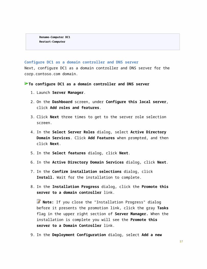
3. Configure EDGE1.
4. Test access to resources on APP1.
The following sections provide details about how to perform these steps.
Step 1: Configure DC1DC1 is a virtual machine running on the HNVHOST4 physical server. DC1 provides the following services:
A domain controller for the corp.fabrikam.com Active Directory Domain Services (AD DS) domain
A DNS server for the corp.fabrikam.com DNS domain
A DHCP server for the Fabrikam Corpnet subnet
DC1 configuration consists of the following:
Install the operating system
Configure TCP/IP
Install Active Directory and DNS
Install DHCP
Create a user account in Active Directory
Install the operating system on DC1First, install Windows Server 2012 R2 as a standalone server.
To install the operating system on DC1
1. Start the installation of Windows Server 2012 R2.
2. Follow the instructions to complete the installation, specifying Windows Server 2012 R2 (full installation) and a strong password for the local Administrator account. Log on using the local Administrator account.
3. Connect DC1 to a network that has Internet access and run Windows Update to install the latest updates for Windows Server 2012 R2.
4. Connect DC1 to the Fabrikam_Corpnet virtual switch on HNVHOST4.
56

Configure TCP/IP properties on DC1Next, configure the TCP/IP protocol with a static IP address of 10.0.0.1 and the subnet mask of 255.255.255.0.
To configure TCP/IP on DC1
1. In Server Manager, click Local Server in the console tree. Click the link next to Ethernet.
2. In Network Connections, right-click Ethernet, and then click Properties.
3. Click Internet Protocol Version 4 (TCP/IPv4), and then click Properties.
4. Select Use the following IP address. In IP address, type 10.0.0.1. In Subnet mask, type 255.255.255.0. In Default gateway, type 10.0.0.2. Select Use the following DNS server addresses. In Preferred DNS server, type 127.0.0.1.
5. Click OK and then close the Ethernet Properties dialog.
6. Close the Network Connections window.
7. From the Tools menu in Server Manager, click Windows PowerShell.
8. To configure the firewall to allow ICMPv4 ping packets, type the following commands and press ENTER after each command.
New-NetFirewallRule –DisplayName “Allow ICMPv4-In” –Protocol ICMPv4
New-NetFirewallRule –DisplayName “Allow ICMPv4-Out” –Protocol ICMPv4 –Direction Outbound
9. Close the Windows PowerShell window.
10. In Server Manager, click Local Server in the console tree. Click the link next to Computer name in the Properties tile.
11. On the Computer Name tab of the System Properties dialog, click Change.
12. In Computer name, type DC1, click OK twice, and then click Close. When you are prompted to restart the computer, click Restart Now.
13. After restarting, login using the local Administrator account.
57

Windows PowerShell equivalent commands
The following Windows PowerShell cmdlet or cmdlets perform the same function as the preceding procedure. Enter each cmdlet on a single line, even though they may appear word-wrapped across several lines here because of formatting constraints.
New-NetIPAddress -InterfaceAlias Ethernet -IPAddress 10.0.0.1 -AddressFamily IPv4 -PrefixLength 24 -DefaultGateway 10.0.0.2Set-DnsClientServerAddress -InterfaceAlias Ethernet -ServerAddresses 127.0.0.1New-NetFirewallRule –DisplayName “Allow ICMPv4-In” –Protocol ICMPv4New-NetFirewallRule –DisplayName “Allow ICMPv4-Out” –Protocol ICMPv4 –Direction OutboundRename-Computer DC1Restart-Computer
Configure DC1 as a domain controller and DNS serverNext, configure DC1 as a domain controller and DNS server for the corp.fabrikam.com domain.
To configure DC1 as a domain controller and DNS server
1. Launch Server Manager.
2. On the Dashboard screen, under Configure this local server, click Add roles and features.
3. Click Next three times to get to the server role selection screen.
4. In the Select Server Roles dialog, select Active Directory Domain Services. Click Add Features when prompted, and then click Next.
5. In the Select features dialog, click Next.
6. In the Active Directory Domain Services dialog, click Next.
7. In the Confirm installation selections dialog, click Install. Wait for the installation to complete.
8. In the Installation Progress dialog, click the Promote this server to a domain controller link.
Note: If you close the "Installation Progress" dialog before it presents the promotion link, click the gray Tasks flag in the upper right section of Server Manager. When the installation is complete you will see the Promote this server to a Domain Controller
58

link.
9. In the Deployment Configuration dialog, select Add a new forest. In the Root domain name field, type corp.fabrikam.com. Click Next.
10. In the Domain Controller Options dialog, leave the default values, specify a strong DSRM password twice, and then click Next four times to accept default settings for DNS, NetBIOS, and directory paths.
11. In the Review Options dialog, review your selections and then click Next.
Note: You can also click the View script button to review and save the PowerShell commands that Server Manager will run during DC Promotion.
12. In the Prerequisites Check dialog, allow the validation to complete and verify that no errors are reported. Since this is the first DNS server deployment in the forest, you can safely ignore all warnings regarding DNS delegation. Click Install to start the domain controller promotion. Allow the installation to complete.
13. Allow the domain controller to restart. After the server restarts, logon using the CORP\Administrator credentials.
Windows PowerShell equivalent commands
The following Windows PowerShell cmdlet or cmdlets perform the same function as the preceding procedure. Enter each cmdlet on a single line, even though they may appear word-wrapped across several lines here because of formatting constraints.
Install-WindowsFeature AD-Domain-Services -IncludeManagementToolsInstall-ADDSForest -DomainName corp.fabrikam.com
Install and configure DHCP on DC1Next, configure DC1 as DHCP server so that remote computers can automatically obtain an IP address when establishing site-to-site VPN connections.
To install and configure the DHCP server role on DC1
1. In the Dashboard console of Server Manager, under Configure this local server, click Add roles and features.
59

2. Click Next three times to get to the server role selection screen.
3. In the Select server roles dialog, select DHCP Server, click Add Features when prompted, and then click Next.
4. In the Select features dialog, click Next.
5. Click Next on the DHCP Server screen, and then click Install.
6. Allow the installation to complete, and then in the Results window, click the link for Complete DHCP configuration.
7. In the DHCP Post-Install configuration wizard, click Next, and then click Commit.
8. On the Summary page, click Close.
9. In the Add Roles and Features Wizard, click Close.
10. From the Tools menu in Server Manager, click DHCP.
11. In the DHCP console tree, expand dc1.corp.fabrikam.com, and click IPv4. Right-click IPv4, and click New Scope.
12. Click Next in the New Scope Wizard.
13. Type Corpnet for scope name, and then click Next.
14. Next to Start IP Address, type 10.0.0.100, next to End IP Address, type 10.0.0.200, and next to Subnet Mask, type 255.255.255.0.
15. Click Next eight times to accept all scope option default settings, and then click Finish.
16. Close the DHCP Manager console.
Windows PowerShell equivalent commands
The following Windows PowerShell cmdlet or cmdlets perform the same function as the preceding procedure. Enter each cmdlet on a single line, even though they may appear word-wrapped across several lines here because of formatting constraints.
Install-WindowsFeature DHCP -IncludeManagementToolsNetsh DHCP add securitygroupsAdd-DhcpServerInDC -DnsName dc1.corp.fabrikam.comAdd-DhcpServerv4Scope -name "Corpnet" -StartRange 10.0.0.100 -EndRange 10.0.0.200 -
60

SubnetMask 255.255.255.0Set-DhcpServerv4OptionValue -DnsDomain corp.fabrikam.com -DnsServer 10.0.0.1
Create a user account in Active Directory on DC1Next, create a user account in Active Directory that will be used when logging in to CORP domain member computers.
To create a user account in Active Directory
1. From the Tools menu in Server Manager, click Active Directory Administrative Center.
2. In the console tree, click the arrow to expand corp (local), and then double-click Users. This adds Users as a recent navigation link in the console tree.
3. In the Tasks pane, click New, and then click User.
4. In the Create User dialog, type User1 next to Full name and type User1 next to User SamAccountName logon: corp\.
5. In Password, type the password that you want to use for this account, and in Confirm password, type the password again.
6. Under Password options, select Other password options, and select Password never expires.
7. Scroll down to access the Member of section of the Create User dialog, and click Add. Type Domain Admins; Enterprise Admins, and then click OK.
8. Click OK to close the Create User dialog.
9. Exit the Active Directory Administrative Center.
10. Sign out of DC1 as the Administrator user, and then sign in using the User1 account.
Windows PowerShell equivalent commands
The following Windows PowerShell cmdlet or cmdlets perform the same function as the preceding procedure. Enter each cmdlet on a single line, even though they may appear word-wrapped across several lines here because of formatting constraints.
Note that the first command results in a prompt to supply the user password.
61

New-ADUser -SamAccountName User1 -AccountPassword (read-host "Set user password" -assecurestring) -name "User1" -enabled $true -PasswordNeverExpires $true -ChangePasswordAtLogon $false
Add-ADPrincipalGroupMembership -Identity "CN=User1,CN=Users,DC=corp,DC=fabrikam,DC=com" -MemberOf "CN=Enterprise Admins,CN=Users,DC=corp,DC=fabrikam,DC=com","CN=Domain Admins,CN=Users,DC=corp,DC=fabrikam,DC=com"
Step 2: Configure APP1APP1 is a virtual machine running on the HNVHOST4 server. APP1 provides web and file sharing services. APP1 configuration consists of the following:
Install the operating system.
Configure TCP/IP.
Join the computer to the domain.
Install the Web Server (IIS) role.
Create a shared folder.
Install the operating system on APP1
To install the operating system on APP1
1. Start the installation of Windows Server 2012 R2.
2. Follow the instructions to complete the installation, specifying a strong password for the local Administrator account. Log on using the local Administrator account.
3. Connect APP1 to a network that has Internet access and run Windows Update to install the latest updates for Windows Server 2012 R2.
4. Connect APP1 to the Fabrikam_Corpnet virtual switch on HNVHOST4.
Configure TCP/IP properties on APP1
To configure TCP/IP properties on APP1
1. In Server Manager, click Local Server in the console tree. Click the link next to Ethernet in the
62
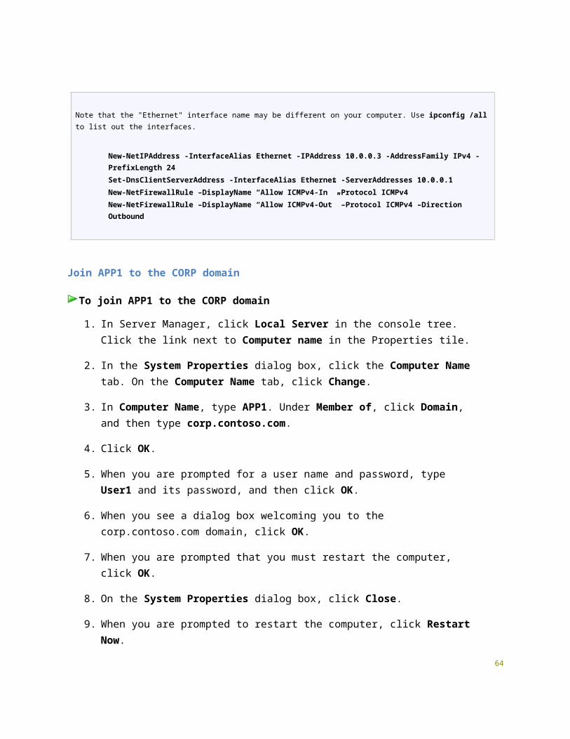
Properties tile.
2. In Network Connections, right-click Ethernet, and then click Properties.
3. Click Internet Protocol Version 4 (TCP/IPv4), and then click Properties.
4. Select Use the following IP address. In IP address, type 10.0.0.3. In Subnet mask, type 255.255.255.0.
5. Select Use the following DNS server addresses. In Preferred DNS server, type 10.0.0.1.
6. Click OK, and then click Close. Close the Network Connections window.
7. From the Tools menu in Server Manager, click Windows PowerShell.
8. To configure the firewall to allow ICMPv4 ping packets, type the following commands and press ENTER after each command.
New-NetFirewallRule –DisplayName “Allow ICMPv4-In” –Protocol ICMPv4
New-NetFirewallRule –DisplayName “Allow ICMPv4-Out” –Protocol ICMPv4 –Direction Outbound
9. To check name resolution and network communication between APP1 and DC1, type ping dc1.corp.fabrikam.com in the command prompt window and press ENTER.
10. Verify that there are four replies from 10.0.0.1.
11. Close the Windows PowerShell window.
Windows PowerShell equivalent commands
The following Windows PowerShell cmdlet or cmdlets perform the same function as the preceding procedure. Enter each cmdlet on a single line, even though they may appear word-wrapped across several lines here because of formatting constraints.
New-NetIPAddress -InterfaceAlias Ethernet -IPAddress 10.0.0.3 -AddressFamily IPv4 -PrefixLength 24Set-DnsClientServerAddress -InterfaceAlias Ethernet -ServerAddresses 10.0.0.1New-NetFirewallRule –DisplayName “Allow ICMPv4-In” –Protocol ICMPv4New-NetFirewallRule –DisplayName “Allow ICMPv4-Out” –Protocol ICMPv4 –Direction Outbound
63

Join APP1 to the CORP domain
To join APP1 to the CORP domain
1. In Server Manager, click Local Server in the console tree. Click the link next to Computer name in the Properties tile.
2. In the System Properties dialog box, click the Computer Name tab. On the Computer Name tab, click Change.
3. In Computer Name, type APP1. Under Member of, click Domain, and then type corp.fabrikam.com.
4. Click OK.
5. When you are prompted for a user name and password, type User1 and its password, and then click OK.
6. When you see a dialog box welcoming you to the corp.fabrikam.com domain, click OK.
7. When you are prompted that you must restart the computer, click OK.
8. On the System Properties dialog box, click Close.
9. When you are prompted to restart the computer, click Restart Now.
10. After the computer restarts, click the Switch User arrow icon, then click Other User and log on to the CORP domain with the User1 account.
Windows PowerShell equivalent commands
The following Windows PowerShell cmdlet or cmdlets perform the same function as the preceding procedure. Enter each cmdlet on a single line, even though they may appear word-wrapped across several lines here because of formatting constraints.
Note that you must supply domain credentials after entering the Add-Computer command below.
Add-Computer -NewName APP1 -DomainName corp.fabrikam.comRestart-Computer
Install the Web Server (IIS) role on APP1Next, install the Web Server (IIS) role to make APP1 a web server.
64

To install the Web Server (IIS) server role
1. In the Dashboard console of Server Manager, click Add roles and features.
2. Click Next three times to get to the server role selection screen.
3. In the Select Server Roles dialog, select Web Server (IIS), and then click Next.
4. Click Next three times to accept the default Web Server role settings, and then click Install.
5. Allow the installation to complete, and then click Close.
Windows PowerShell equivalent commands
The following Windows PowerShell cmdlet or cmdlets perform the same function as the preceding procedure. Enter each cmdlet on a single line, even though they may appear word-wrapped across several lines here because of formatting constraints.
Install-WindowsFeature Web-WebServer -IncludeManagementTools
Create a shared folder on APP1Next, create a shared folder and a text file within the folder.
To create a shared folder
1. From the desktop taskbar, click File Explorer.
2. Expand This PC, and then double-click Local Disk (C:).
3. Right-click in the details pane, point to New, and then click Folder.
4. Type Files, and then press ENTER. Leave the Local Disk window open.
5. From the Start screen, click the down arrow for the All Apps link, and then type Notepad. Right-click Notepad, and then click Run as administrator.
6. In the Untitled – Notepad window, type This is a shared file.
7. Click File, click Save, double-click This PC, double-click Local Disk (C:), and then double-
65

click the Files folder.
8. In File name, type Example.txt, and then click Save. Close the Notepad window.
9. In the Local Disk window, right-click the Files folder, point to Share with, and then click Specific people.
10. Click Share, and then click Done.
11. Close the Local Disk window.
Windows PowerShell equivalent commands
The following Windows PowerShell cmdlet or cmdlets perform the same function as the preceding procedure. Enter each cmdlet on a single line, even though they may appear word-wrapped across several lines here because of formatting constraints.
New-Item -path c:\Files -type directoryWrite-Output "This is a shared file." | out-file c:\Files\example.txtNew-SmbShare -name files -path c:\Files -changeaccess CORP\User1
Step 3: Configure EDGE1EDGE1 is a virtual machine running on the HNVHOST4 server. EDGE1 configuration consists of the following:
Install the operating system.
Configure TCP/IP.
Join the computer to the domain.
EDGE1 must have two network adapters installed. Connect one adapter to the Fabrikam_Corpnet virtual switch on HNVHOST4, and connect the second adapter to the Internet virtual switch on HNVHOST4.
Install the operating system on EDGE1First, install Windows Server 2012 R2 as a standalone server.
To install the operating system on EDGE1
1. Start the installation of Windows Server 2012 R2.
2. Follow the instructions to complete the installation, specifying Windows Server 2012 R2
66
(full installation) and a strong password for the local Administrator account. Log on using the local Administrator account.
3. Connect EDGE1 to a network that has Internet access and run Windows Update to install the latest updates for Windows Server 2012 R2.
4. Connect one network adapter to the Fabrikam_Corpnet virtual switch and the other to the Internet virtual switch on HNVHOST4.
Configure TCP/IP properties on EDGE1Configure the TCP/IP protocol with static IP addresses on both interfaces.
To configure TCP/IP properties on the Corpnet adapter
1. In Server Manager, click Local Server in the console tree. Click the link next to Ethernet in the Properties tile.
2. In Network Connections, right-click the network connection that is connected to the Corpnet subnet, and then click Rename.
3. Type Corpnet, and then press ENTER.
4. Right-click Corpnet, and then click Properties.
5. Click Internet Protocol Version 4 (TCP/IPv4), and then click Properties.
6. Select Use the following IP address. In IP address, type 10.0.0.2. In Subnet mask, type 255.255.255.0.
7. Select Use the following DNS server addresses. In Preferred DNS server, type 10.0.0.1.
8. Click Advanced, and then the DNS tab.
9. In DNS suffix for this connection, type corp.fabrikam.com, and then click OK three times to close the network properties dialog.
10. In the Network Connections window, right-click the network connection that is connected to the Internet subnet, and then click Rename.
11. Type Internet, and then press ENTER.
12. Right-click Internet, and then click Properties.
13. Click Internet Protocol Version 4 (TCP/IPv4), and then click Properties.
67

14. Select Use the following IP address. In IP address, type 131.107.0.5. In Subnet mask, type 255.255.255.0.
15. Select Use the following DNS server addresses. In Preferred DNS server, type 131.107.0.1.
16. Click Advanced. Click the DNS tab.
17. In DNS suffix for this connection, type isp.example.com, and then click OK three times to close the network properties dialog.
18. Close the Network Connections window.
19. From the Tools menu in Server Manager, click Windows PowerShell.
20. To configure the firewall to allow ICMPv4 ping packets, type the following commands and press ENTER after each command.
New-NetFirewallRule –DisplayName “Allow ICMPv4-In” –Protocol ICMPv4
New-NetFirewallRule –DisplayName “Allow ICMPv4-Out” –Protocol ICMPv4 –Direction Outbound
21. To check name resolution and network communication between EDGE1 and DC1, type ping dc1.corp.fabrikam.com in the command prompt window and press ENTER.
22. Verify that there are four responses from 10.0.0.1.
23. Close the Windows PowerShell window.
Windows PowerShell equivalent commands
The following Windows PowerShell cmdlet or cmdlets perform the same function as the preceding procedure. Enter each cmdlet on a single line, even though they may appear word-wrapped across several lines here because of formatting constraints.
Note: Prior to executing these commands, rename the network connections to Corpnet and Internet according to their associated subnets.
New-NetIPAddress -InterfaceAlias "Corpnet" -IPAddress 10.0.0.2 -AddressFamily IPv4 -PrefixLength 24Set-DnsClientServerAddress -InterfaceAlias "Corpnet" -ServerAddresses 10.0.0.1Set-DnsClient -InterfaceAlias "Corpnet" -ConnectionSpecificSuffix corp.fabrikam.comNew-NetIPAddress -InterfaceAlias "Internet" -IPAddress 131.107.0.5 -AddressFamily IPv4 -PrefixLength 24
68

Set-DnsClientServerAddress -InterfaceAlias "Internet" -ServerAddresses 131.107.0.1Set-DnsClient -InterfaceAlias "Internet" -ConnectionSpecificSuffix isp.example.comNew-NetFirewallRule –DisplayName “Allow ICMPv4-In” –Protocol ICMPv4New-NetFirewallRule –DisplayName “Allow ICMPv4-Out” –Protocol ICMPv4 –Direction Outbound
Join EDGE1 to the CORP domain
To join EDGE1 to the CORP domain
1. In Server Manager, click Local Server in the console tree. Click the link next to Computer name in the Properties tile.
2. In the System Properties dialog box, click the Computer Name tab. On the Computer Name tab, click Change.
3. In Computer Name, type EDGE1. Under Member of, click Domain, and then type corp.fabrikam.com.
4. Click OK.
5. When you are prompted for a user name and password, type User1 and its password, and then click OK.
6. When you see a dialog box welcoming you to the corp.fabrikam.com domain, click OK.
7. When you are prompted that you must restart the computer, click OK.
8. On the System Properties dialog box, click Close.
9. When you are prompted to restart the computer, click Restart Now.
10. After the computer restarts, click the Switch User arrow icon, then click Other User and log on to the CORP domain with the User1 account.
Windows PowerShell equivalent commands
The following Windows PowerShell cmdlet or cmdlets perform the same function as the preceding procedure. Enter each cmdlet on a single line, even though they may appear word-wrapped across several lines here because of formatting constraints.
69

Note that you must supply domain credentials after entering the Add-Computer command below.
Add-Computer -NewName EDGE1 -DomainName corp.fabrikam.comRestart-Computer
Step 4: Test access to resources on APP1Test connectivity to file and web resources on APP1 from DC1 while APP1 is directly connected to the Fabrikam Corpnet subnet. Later, APP1 will be moved to the simulated service provider datacenter.
To test access to file and web resources on APP1
1. Sign in to DC1 using the CORP\User1 domain account.
2. From the desktop taskbar, click the File Explorer icon.
3. In the address bar, type \\app1\Files, and then press ENTER.
4. You should see a folder window with the contents of the Files shared folder.
5. In the Files shared folder window, double-click the Example.txt file. You should see the contents of the Example.txt file.
6. Close the Example - Notepad window.
7. Close File Explorer.
8. In Server Manager, select Local Server in the console tree.
9. Under Properties for DC1, next to IE Enhanced Security Configuration, click On.
10. Change the IE ESC option to Off for Administrators. Click OK.
11. Launch Internet Explorer.
12. In the address bar, type http://app1.corp.fabrikam.com and then press ENTER.
13. Verify that the default Internet Information Services web page is displayed from APP1.
14. Close Internet Explorer.
70

Steps for Installing and Configuring System Center 2012 R2 Virtual Machine Manager There are six steps to installing and configuring System Center 2012 R2 Virtual Machine Manager on the HNVHOST2 server.
1. Install Windows Assessment and Deployment Kit (ADK) 8.1
2. Install and configure SQL Server 2012.
3. Install and configure System Center 2012 R2 Virtual Machine Manager.
4. Configure a Gateway VM on HNVHOST3.
5. Deploy the Microsoft Software Gateway.
6. Install and configure IPAM on HNVHOST2.
Step 1: Install Windows Assessment and Deployment Kit (ADK)HNVHOST2 is a physical server configured as a Windows Server 2012 R2 Hyper-V host and simulated service provider network hnv.adatum.com domain member. The next step is to install Windows Assessment and Deployment Kit (ADK) on HNVHOST2 in preparation for installation of System Center 2012 R2 Virtual Machine Manager. Windows ADK is available at the Microsoft Download Center. If HNVHOST2 has Internet access, you can run the installation using ADKSetup.exe. ADK Setup downloads installation packages from the Internet while it runs. If HNVHOST2 does not have Internet access, copy the offline installation package to HNVHOST2. For instruction on installing Windows ADK on an offline computer, see the Appendix section of this document.
Install Windows Assessment and Deployment Kit (ADK) on HNVHOST2
To install the Windows ADK on HNVHOST2
1. Right-click ADKSetup.exe, and then click Run as administrator.
2. Click Install the Assessment and Deployment Kit to this computer, specify the location where you want to install the Windows ADK features, and then click Next.
3. On the CEIP screen, click Next.
4. Click Accept to accept the license agreement.
5. On the feature selection screen, select Deployment Tools and Windows Preinstallation Environment (Windows PE). ). Clear the check boxes for the other default ADK installation features. Click Install.
71
6. Wait for the installation to complete, and then click Close.
Step 2: Install and configure SQL Server 2012The next step is to install SQL Server 2012 on HNVHOST2 in preparation for installation of System Center Virtual Machine Manager.
Install SQL Server 2012 on HNVHOST2
To install SQL Server 2012 on HNVHOST2
1. Insert the SQL Server installation media. From the root folder, double-click Setup.exe. To install from a network share, locate the root folder on the share, and then double-click Setup.exe.
2. The Installation Wizard runs the SQL Server Installation Center. To create a new installation of SQL Server, click Installation in the left-hand navigation area, and then click New SQL Server stand-alone installation or add features to an existing installation.
3. The System Configuration Checker runs a discovery operation. To continue, click OK. You can view the details on the screen by clicking Show Details, or as an HTML report by clicking View detailed report.
4. On the Product Key page, select an option to indicate whether you are installing a free edition of SQL Server, or a production version of the product that has a PID key.
5. To continue, click Next.
6. On the License Terms page, review the license agreement, select the I accept the license terms check box, and then click Next. To help improve SQL Server, you can also enable the feature usage option and send reports to Microsoft.
7. On the Product Updates page, the latest available SQL Server product updates are displayed. If you don't want to include the updates, clear the Include SQL Server product updates check box. If no product updates are discovered, SQL Server Setup does not display this page and auto advances to the Install Setup Files page.
8. On the Install Setup files page, Setup provides the progress of downloading, extracting, and installing the Setup files. If an update for SQL Server Setup is found, and is specified to be included, that update will also be installed.
9. On the Setup Support Rules page, click Next.
72
10. On the Setup Role page, select SQL Server Feature Installation, and then click Next.
11. On the Feature Selection page, under Instance Features, select Database Engine Services. Click Next to continue.
12. On the Installation Rules page, Setup verifies the system state of your computer before Setup continues. Click Next to continue.
13. On the Instance Configuration page, specify Default instance. Click Next to continue.
14. Click Next on the Disk Space Requirements page.
15. On the Server Configuration page, click Next.
16. On the Server Configuration tab of the Database Engine Configuration page, click Add Current User to specify a SQL Server administrator, and then click Next.
17. On the Error Reporting page, specify the information that you want to send to Microsoft that will help improve SQL Server. Click Next.
18. The System Configuration Checker will run a set of rules to validate your computer configuration with the SQL Server features that you have specified. Click Next.
19. The Ready to Install page shows a tree view of installation options that were specified during Setup. On this page, Setup indicates whether the Product Update feature is enabled or disabled and the final update version. To continue, click Install. SQL Server Setup will first install the required prerequisites for the selected features followed by the feature installation.
20. During installation, the Installation Progress page provides status so that you can monitor installation progress as Setup continues.
21. After installation, the Complete page provides a link to the summary log file for the installation and other important notes. To complete the SQL Server installation process, click Close.
Step 3: Install and configure System Center 2012 R2 Virtual Machine Manager
Install System Center Virtual Machine Manager on HNVHOST2HNVHOST2 configuration consists of the following:
Install System Center 2012 R2 Virtual Machine Manager (VMM).
Configure System Center VMM.73

To install System Center Virtual Machine Manager on HNVHOST2
1. To start the Virtual Machine Manager Setup Wizard, on your installation media, right-click setup.exe, and then click Run as administrator.
Note Before beginning the installation of VMM, close any open programs and ensure that there are no pending restarts on the computer. For example, if you have installed a server role by using Server Manager or have applied a security update, you may need to restart the computer and then log on to the computer with the same user account to finish the installation of the server role or the security update.
2. On the main setup page, click Install.
3. If you have not installed Microsoft .NET Framework, VMM will prompt you to install now.
4. On the Select features to install page, select the VMM management server check box, and then click Next.
Note The VMM console is automatically installed when you install a VMM management server.
5. On the Product registration information page, provide the appropriate information, and then click Next.
6. On the Please read this license agreement page, review the license agreement, select the I have read, understood, and agree with the terms of the license agreement check box, and then click Next.
7. On the Join the Customer Experience Improvement Program (CEIP) page, select either option and then click Next.
8. On the Microsoft Update page, select whether to deliver VMM updates automatically, and then click Next.
9. On the Installation location page, use the default path or type a different installation path for the VMM program files, and then click Next.
10. The computer on which you are installing the VMM management server will be checked to ensure that the appropriate hardware and software requirements are met. If a prerequisite is not met, a page will appear with information about which prerequisite has not been met and how to resolve the issue. If all prerequisites have been met, the
74

Database configuration page appears.
11. On the Database configuration page, do the following:
Specify HNVHOST2 as the server name.
Leave the Port box empty.
Select New database, and accept the default name VirtualManagerDB.
Click Next.
12. On the Configure service account and distributed key management page, select Local System account. Click Next.
13. On the Port configuration page, use the default port numbers, and then click Next.
Important The ports that you assign during the installation of a VMM management server cannot be changed without uninstalling and reinstalling the VMM management server.
14. On the Library configuration page, ensure that Create a new library share is selected, and then click Next.
Note The default library share created by VMM is named MSSCVMMLibrary and the folder is located at %SYSTEMDRIVE%\ProgramData\Virtual Machine Manager Library Files. ProgramData is a hidden folder.
After the VMM management server is installed, you can add library shares and additional library servers by using the VMM console or by using the VMM command shell.
15. On the Installation summary page, review your selections and then click Install to install the VMM management server.
16. After you click Install, the Installing features page appears and installation progress is displayed. On the Setup completed successfully page, click Close to finish the installation.
17. To open the VMM console, ensure that the Open the VMM console when this wizard closes check box is selected.
Note
If there is a problem with setup completing successfully, consult the log files in the 75

%SYSTEMDRIVE%\ProgramData\VMMLogs folder. ProgramData is a hidden folder.
Configure System Center Virtual Machine Manager on HNVHOST2HNVHOST2 is a physical server configured as a Windows Server 2012 R2 Hyper-V host, SQL server, and System Center 2012 R2 Virtual Machine Manager, connected to a shared physical switch used to simulate a service provider datacenter connection (Hosternet). Configuration of System Center 2012 R2 VMM on HNVHOST2 consists of the following:
Add HNVHOST1, HNVHOST2 and HNVHOST3 as VMM Hosts
Define the Management logical network
Create an IP pool associated with the Management logical network
Define the Internet logical network
Create an IP pool associated with the Internet logical network
Define the Back End (NetVirt) logical network
Create an IP pool associated with the Back End (NetVirt) logical network
Define VM networks for Management and Internet
Create port profiles and logical switches
Assign logical networks, virtual switches, and virtual adapters to the VMM host servers
First, add the test lab Hyper-V host servers as VMM hosts, so that they can host tenant VMs using network virtualization.
To add HNVHOST1, HNVHOST2 and HNVHOST3 as VMM Hosts
1. Restart both HNVHOST1 and HNVHOST2 servers to ensure that no pending restarts will prevent adding them as VMM-managed hosts.
2. From the desktop shortcut on HNVHOST2, click Virtual Machine Manager Console.
3. Click Connect.
4. Open the Fabric workspace.
76

5. In the Fabric pane, expand Servers, and then select All Hosts.
6. On the Home tab, in the Add group, click Add Resources, and then click Hyper-V Hosts and Clusters. The Add Resource Wizard starts.
7. On the Resource location page, click Windows Server computers in a trusted Active Directory domain, and then click Next.
8. On the Credentials page, next to Run As account, click Browse.
9. In the Select a Run As Account dialog, click Create Run As Account. Next to name, type Adatum User1. Next to User name, type HNV\User1. Type the password for User1, and then confirm the password. Click OK.
10. In the Select a Run As Account dialog, select Adatum User1, and then click OK.
11. On the Credentials page, click Next.
12. On the Discovery Scope page, click Specify Windows Server computers by names. In the Computer names box, enter HNVHOST1, HNVHOST2, and HNVHOST3. Type each server name on its own line in the entry window. Click Next.
13. On the Target resources page, click Select all to select HNVHOST1.hnv.adatum.com, HNVHOST2.hnv.adatum.com, and HNVHOST3.hnv.adatum.com, and then click Next. Click OK in the resultant dialog prompt.
14. On the Host settings page, click Next.
15. On the Summary page, confirm the settings, and then click Finish.
16. The Jobs dialog box appears to show the job status. Make sure that the job has a status of Completed w/ Info, and then close the dialog box.
17. To verify that the host servers were successfully added, in the Fabric pane, select All Hosts, and then in the Hosts pane, verify that the host status for each server is listed as OK.
Define logical networks with associated IP poolsA logical network, together with one or more associated network sites, is a user-defined named grouping of IP subnets, VLANs, or IP subnet/VLAN pairs that is used to organize and simplify network assignments. Define logical networks with associated network sites and IP pools in VMM for Management, Internet, and Back End (NetVirt). Then define VM networks for Management and Internet.
77

To define the Management logical network
1. In the Fabric pane, expand Networking, and then click Logical Networks. Logical networks represent an abstraction of the underlying physical network infrastructure. By default, when you add a Hyper-V host to VMM management, VMM automatically creates logical networks that match the first DNS suffix label of the connection-specific DNS suffix on each host network adapter. Since we added connection-specific DNS suffixes to the host adapters, they are easily identified in this interface.
2. In the Logical Networks detail pane, right-click the logical network named HNV, and then click Properties.
3. Change the Name value to Management. Click Network Site. Under Network sites, click Add.
4. Under Host groups that can use this network site, select All Hosts.
5. Under Associated VLANs and IP subnets, click Insert row. Type 192.168.0.0/24 under IP subnet. Click OK.
To create an IP pool for the Management logical network
1. In the Fabric pane, expand Networking, and then click Logical Networks.
2. Right-click Management, and then click Create IP Pool.
3. The Create Static IP Address Pool Wizard opens.
4. On the Name page, enter Management IP Pool as the name. Click Next.
5. In the Network Site page, verify that Use an existing network site is selected, and that Management_0 is selected with IP subnet 192.168.0.0/24.
6. Click Next.
7. On the IP address range page, change the Starting IP address to 192.168.0.100. Change Ending IP address to 192.168.0.200. Click Next.
8. On the Gateway page, click Next.
9. On the DNS page, next to DNS server address, click Insert. Type a DNS Server address of 192.168.0.1. Next to DNS suffix, click Insert. Type a DNS suffix of hnv.adatum.com. Click Next.
78

10. On the WINS page, click Next.
11. On the Summary page, click Finish.
To define the Internet logical network
1. In the Logical Networks detail pane, right-click the logical network named isp, and then click Properties.
2. Change the Name value to Internet. Next to Description, type External Networks.
3. Click Network Site. Under Network sites, click Add.
4. Under Host groups that can use this network site, select All Hosts.
5. Under Associated VLANs and IP subnets, click Insert row. Type 131.107.0.0/24 under IP subnet. Click OK.
To create an IP pool for the Internet logical network
1. Right-click Internet, and then click Create IP Pool.
2. The Create Static IP Address Pool Wizard opens.
3. On the Name page, enter Internet IP Pool as the name. Click Next.
4. In the Network Site page, verify that Use an existing network site is selected, and that Internet_0 is selected with IP subnet 131.107.0.0/24.
5. Click Next.
6. On the IP address range page, change the Starting IP address to 131.107.0.15. Change Ending IP address to 131.107.0.29. Click Next.
7. On the Gateway page, click Next.
8. On the DNS page, next to DNS server address, click Insert. Type a DNS Server address of 131.107.0.1. Next to DNS suffix, click Insert. Type a DNS suffix of isp.example.com. Click Next.
9. On the WINS page, click Next.
10. On the Summary page, click Finish.
79

To define the Back End (NetVirt) logical network
1. Right-click Logical Networks, and then click Create Logical Network. The Create Logical Network wizard launches.
2. Next to Name, type Back End (NetVirt). Next to Description, type Tenant Networks. Under One connected network, select the checkbox box Allow new VM networks created on this logical network to use network virtualization.
3. Click Next. Under Network sites, click Add.
4. Under Host groups that can use this network site, select All Hosts.
5. Under Associated VLANs and IP subnets, click Insert row. Type 172.16.1.0/24 under IP subnet. Click Next.
6. On the Summary page, click Finish.
To create an IP pool for the Back End (NetVirt) logical network
1. In the Fabric pane, expand Networking, and then click Logical Networks.
2. Right-click Back End (NetVirt), and then click Create IP Pool.
3. The Create Static IP Address Pool Wizard opens.
4. On the Name page, enter NetVirt IP Pool as the name. Next to Logical network, select Back End (NetVirt). Click Next.
5. In the Network Site page, verify that Use an existing network site is selected, and that Back End (NetVirt)_0 is selected with IP subnet 172.16.1.0/24.
6. Click Next.
7. On the IP address range page, change the Starting IP address to 172.16.1.100. Change Ending IP address to 172.16.1.200. Click Next.
8. On the Gateway page, click Next.
9. On the DNS page, click Next.
10. On the WINS page, click Next.
11. On the Summary page, click Finish.
80

Define VM networks VM networks offer the ability to use network virtualization, which extends the concept of server virtualization to make it possible for you to deploy multiple virtual networks on the same physical network. Define VM networks in VMM for Management and Internet.
To define VM networks for Management and Internet
1. Open the VMs and Services workspace.
2. Under VMs and Services, select VM Networks.
3. Right-click the VM Network named HNV, and then click Properties.
4. On the Name page, change the name to Management, and then in the Logical network list, select Management. Click OK.
5. Right-click the VM Network named isp, and then click Properties.
6. On the Name page, change the name to Internet, and then in the Logical network list, select Internet. Click OK.
Create port profiles and logical switchesIn Virtual Machine Manager (VMM) in System Center 2012 R2, you can consistently configure identical capabilities for network adapters across multiple hosts by using port profiles and logical switches. Port profiles and logical switches act as containers for the properties or capabilities that you want your network adapters to have. Instead of configuring individual properties or capabilities for each network adapter, you can specify the capabilities in port profiles and logical switches, which you can then apply to the appropriate adapters.
To create port profiles for Hosternet and External
1. In Virtual Machine Manager Console on HNVHOST2, open the Fabric workspace.
2. Expand Networking in the console tree.
3. Right-click Port Profiles, and then click Create Hyper-V Port Profile. The Create Hyper-V Port Profile wizard opens.
4. Next to Name, type External.
5. Select Uplink port profile, and then click Next.
6. On the Network configuration screen, select Internet_0 as the network site supported
81

by this uplink port profile, and then click Next.
7. On the Summary page, click Finish.
8. The Jobs dialog box appears to show the job status. Make sure that the job has a status of Completed, and then close the dialog box.
9. Right-click Port Profiles, and then click Create Hyper-V Port Profile. The Create Hyper-V Port Profile wizard opens.
10. Next to Name, type Hosternet.
11. Select Uplink port profile, and then click Next.
12. On the Network configuration screen, select both Back End (NetVirt)_0 and Management_0 as the network sites supported by this uplink port profile. Select the checkbox for Enable Hyper-V Network Virtualization. Click Next.
Note The checkbox for Enable Hyper-V Network Virtualization is only required when applied to a Windows Server 2012 Hyper-V host, and it enables the HNV filter driver for the adapter to which this port profile applies. In Windows Server 2012 R2, the HNV driver is now part of the virtual switch, and does not need to be bound to individual physical adapters.
13. On the Summary page, click Finish.
14. The Jobs dialog box appears to show the job status. Make sure that the job has a status of Completed, and then close the dialog box.
15. Right-click Port Profiles, and then click Create Hyper-V Port Profile. The Create Hyper-V Port Profile wizard opens.
16. Next to Name, type HNVNIC.
17. Select Virtual network adapter port profile, and then click Next.
18. On the Offload Settings screen, click Next.
19. On the Security Settings screen, verify that Allow guest specified IP addresses (only available for virtual machines on Windows Server 2012 R2) is selected, and then click Next.
20. On the Bandwidth Settings screen, click Next.
82

21. On the Summary screen, click Finish.
To create logical switches for Internet (Front End), and Hosternet (Back End)
1. In Virtual Machine Manager Console on HNVHOST2, open the Fabric workspace.
2. Expand Networking in the console tree.
3. Right-click Logical Switches, and then click Create Logical Switch. The Create Logical Switch wizard opens. Click Next.
4. On the General screen, name the logical switch Internet (Front End). Next to Description, type Switch used to provide S2S VPN connectivity, and then click Next.
5. On the Extensions screen, click Next.
6. On the Uplink screen, click Add. In the Select a port profile dialog, select External from the drop-down list, and then click OK. Click Next.
7. On the Virtual Port screen, click Next.
8. On the Summary screen, click Finish.
9. The Jobs dialog box appears to show the job status. Make sure that the job has a status of Completed, and then close the dialog box.
10. Right-click Logical Switches, and then click Create Logical Switch. The Create Logical Switch wizard opens. Click Next.
11. On the General screen, name the logical switch Hosternet (Back End). Next to Description, type Switch used for HNV tenant networks, and then click Next.
12. On the Extensions screen, click Next.
13. On the Uplink screen, click Add. In the Select a port profile dialog, select Hosternet from the drop-down list, and then click OK. Click Next.
14. On the Virtual Port screen, click Add. In the Configure the virtual port screen, next to Port classification, click Browse. Click Guest Dynamic IP, and then click OK.
15. In the Configure the virtual port screen, select the checkbox for Include a virtual network adapter port profile in this virtual port. Next to Native virtual network adapter port profile, select HNVNIC from the dropdown list. Click OK.
83

16. On the Virtual Port screen, click Next.
17. On the Summary screen, click Finish.
18. The Jobs dialog box appears to show the job status. Make sure that the job has a status of Completed, and then close the dialog box.
Assign logical networks, virtual switches, and virtual adapters to the VMM host serversTo associate the logical networks, virtual switches and virtual adapters with the VMM host servers, assign the appropriate virtual switch settings to each physical adapter by editing the properties of the VMM hosts.
To assign logical networks, virtual switches and virtual adapters to the HNVHOST3 VMM host server
1. Open the Fabric workspace.
2. In the Fabric pane, expand Servers, and then select All Hosts.
3. Right-click HNVHOST3 in the details pane, and then click Properties.
4. Click Virtual Switches.
5. Click New Virtual Switch, and then click New Logical Switch.
6. Next to Logical switch, select Hosternet (Back End). Under Physical adapters, select the physical adapter connected to the Hosternet network on HNVHOST3 from the dropdown list of adapters. Select the Hosternet Uplink Port Profile.
7. Click New Virtual Network Adapter. Next to Name, type Hosternet. Verify that a new virtual adapter is added and connected to the Management VM Network, and that This virtual network adapter inherits settings from the physical management adapter is selected.
8. Click New Virtual Switch, and then click New Logical Switch.
9. Next to Logical switch, select Internet (Front End). Under Physical adapters, select the physical adapter connected to the Internet network on HNVHOST3 from the dropdown list of adapters. Select the External Uplink Port Profile.
10. Click New Virtual Network Adapter. Next to Name, type Internet. Verify that a new virtual adapter is added for Internet, and that This virtual network adapter inherits settings from the physical management adapter is selected.
84

11. Click OK to close the HNVHOST3 properties window, and click OK to acknowledge the warning dialog.
To assign logical networks, virtual switches and virtual adapters to the HNVHOST2 VMM host server
1. Right-click HNVHOST2, and then click Properties.
2. Click Virtual Switches.
3. Click New Virtual Switch, and then click New Logical Switch.
4. Next to Logical switch, select Hosternet (Back End). Under Physical adapters, select the physical adapter connected to the Hosternet network on HNVHOST2 from the dropdown list of adapters. Select the Hosternet Uplink Port Profile.
5. Click New Virtual Network Adapter. Next to Name, type Hosternet. Verify that a new virtual adapter is added and connected to the Management VM Network, and that This virtual network adapter inherits settings from the physical management adapter is selected.
6. Click OK to close the HNVHOST2 properties window, and click OK to acknowledge the warning dialog.
To assign logical networks, virtual switches and virtual adapters to the HNVHOST1 VMM host server
1. Right-click HNVHOST1, and then click Properties.
2. Click Virtual Switches.
3. Click New Virtual Switch, and then click New Logical Switch.
4. Next to Logical switch, select Hosternet (Back End). Under Physical adapters, select the physical adapter connected to the Hosternet network on HNVHOST1 from the dropdown list of adapters. Select the Hosternet Uplink Port Profile.
5. Click New Virtual Network Adapter. Next to Name, type Hosternet. Verify that a new virtual adapter is added and connected to the Management VM Network, and that This virtual network adapter inherits settings from the physical management adapter is selected.
85

6. Click OK to close the HNVHOST1 properties window, and click OK to acknowledge the warning dialog.
Step 4: Configure GatewayVM1 on HNVHOST3GatewayVM1 is a virtual machine configured as a Hyper-V Network Virtualization Gateway for Site-to-Site (S2S) VPN and NAT. GatewayVM1 must be configured with three virtual network adapters. One adapter is connected to the external virtual switch on HNVHOST3 used to simulate an Internet connection, and the other two adapters are connected to the external virtual switch on HNVHOST3 used to simulate a service provider datacenter connection (Hosternet). GatewayVM1 configuration consists of the following:
Add a virtual hard disk for the Gateway virtual machine to the VMM library
Create a VM Template for the Gateway virtual machine
Create and deploy a Service Template for the Gateway virtual machine
Configure network connections on GatewayVM1
Connect the third virtual adapter on GatewayVM1
Add a virtual hard disk for the GatewayVM virtual machine to the VMM libraryIn the next step, you will deploy a gateway virtual machine on the HNVHOST3 server. The gateway consists of a Windows Server 2012 R2 VM performing basic routing, VPN and NAT. This gateway can serve multiple tenants through isolated compartments. The gateway VM runs on a Windows Server 2012 R2 Hyper-V host that is dedicated to network virtualization gateway functionality. The gateway host performs encapsulation and decapsulation of the NVGRE packets. This procedure requires a generalized virtual hard disk stored in the VMM Library. If you already have a generalized Windows Server 2012 R2 VHD to use, name the VHD file Server2012R2Base.vhd, and copy it to the %SYSTEMDRIVE%\ProgramData\Virtual Machine Manager Library Files\VHDs directory on the HNVHOST2 server.
Note The default library share created by VMM is named MSSCVMMLibrary and the folder is located at %SYSTEMDRIVE%\ProgramData\Virtual Machine Manager Library Files. ProgramData is a hidden folder. To browse to this location in File Explorer, you must change the View options to display hidden folders.
For instruction on how to create a generalized hard disk file on HNVHOST2, see the Appendix section of this document.
86

Create a VM Template for the Gateway virtual machineYou can manually create and configure a gateway virtual machine, or you can use VMM to automate the deployment. Use the following process to use a VM Template and Service Template to deploy the gateway VM.
To create a VM Template for the Gateway virtual machine
1. In Virtual Machine Manager Console on HNVHOST2, open the Library workspace.
2. Expand Templates in the console tree.
3. Right-click VM Templates, and then click Create VM Template. The Create VM Template wizard opens.
4. Select Use an existing VM template or a virtual hard disk stored in the library, and then click Browse.
5. Select the Server2012R2Base.vhd, and then click OK.
6. On the Select Source screen, verify that Server2012R2Base.vhd is selected, and then click Next.
7. On the Identity screen, type GatewayVM as the VM Template name, and then click Next.
8. On the Configure Hardware screen, click Processor. Change the number of processors to 2.
9. Click Memory. Click Dynamic, and then set a startup memory value of 1024 MB, and a maximum of 4096 MB.
10. Under Network Adapters, click Network Adapter 1. Select Connected to a VM network under Connectivity, and then click Browse. Click Internet, and then click OK. Under IP address, click Static IP (from a static IP pool).
11. Click New, and then click Network adapter to add a second network adapter.
12. Select Connected to a VM network under Connectivity, and then click Browse. Click Management, and then click OK. Under IP address, click Static IP (from a static IP pool).
13. Click New, and then click Network adapter to add a third network adapter.
14. Leave Network Adapter 3 Not connected for now. Click Next.
15. On the Configure Operating System screen, next to Guest OS profile, select Create new
87

Windows operating system customization settings.
16. Click Operating System, and then select Windows Server 2012 R2 Datacenter.
17. Click Admin Password. Click Select a Run As account for the local administrator account. Click Browse, click Adatum User1, and then click OK.
18. Under Roles and Features, click Roles. Select Remote Access, select DirectAccess and VPN (RAS), and select Routing.
19. Under Roles and Features, click Features. Under Remote Server Administration Tools, Role Administration Tools, select Remote Access Management Tools, select Remote Access GUI and Command-Line Tools, and select Remote Access module for Windows PowerShell.
20. Under Networking, click Domain / Workgroup. Click Domain, and then type hnv.adatum.com.
21. Click Select the Run As account to use for joining the domain, click Browse, click Adatum User1, and then click OK. Click Next.
22. On the Application configuration screen, select Windows Server 2012 R2 Datacenter, and then click Next.
23. On the SQL Server configuration screen, click Next.
24. On the Summary screen, click Create.
25. The Jobs dialog box appears to show the job status. Make sure that the job has a status of Completed, and then close the dialog box.
Create and deploy a Service Template for the VPN and NAT Gateway virtual machine
To create a Service Template for the Gateway virtual machine
1. In Virtual Machine Manager Console on HNVHOST2, open the Library workspace.
2. Expand Templates in the console tree.
3. Right-click Service Templates, and then click Create Service Template. The New Service Template wizard opens.
4. Click Single Machine (v1.0), and then click OK.
88

5. Click New Service Template 1, and change the name to VPN and NAT Gateway VM Template.
6. Click the GatewayVM template under VM Templates, then drag and drop it onto the Single Tier canvas.
7. Right-click GatewayVM - Machine Tier 1, and then click Properties.
8. Click OS Configuration, and then click Identity Information. Type GatewayVM1 under Computer name.
9. Click OK to close the GatewayVM properties dialog.
10. In Virtual Machine Manager Service Template Designer, click Configure Deployment.
11. In the Select name and destination dialog, type Gateway1 next to Name, and then click OK.
12. Initially the Deploy Service dialog will show a red error indicating "No suitable host." Click the Refresh Preview button to re-run intelligent placement until the placement host is listed as HNVHOST3.
13. Click Deploy Service, and then click Deploy in the resulting dialog prompt.
14. The Jobs dialog box appears to show the job status. Make sure that the job has a status of Completed, and then close the dialog box. Deployment may take 30-40 minutes depending on the size of the VHD image for the OS and the speed of the hardware used.
15. After the job completes successfully, switch to the HNVHOST3 server.
Configure network connections on GatewayVM1GatewayVM1 has three virtual adapters, with one connected to the Internet virtual switch and two connected to the Hosternet virtual switch. To configure and name the connections appropriately, you must first determine which adapter is connected to the Internet virtual switch.
To determine the Internet network connection on GatewayVM1
1. Connect to the GatewayVM1 virtual machine, and sign in using the User1 Adatum domain account. Verify that the RRAS role was installed by the VMM Service Template.
2. From the Tools menu in Server Manager, click Windows PowerShell.
3. Type ipconfig /all and press ENTER to display the Windows IP Configuration on GatewayVM1. Note the name of the adapter to which it is assigned the IP address
89

131.107.0.15.
4. In Server Manager on GatewayVM1, click Local Server in the console tree. Click the link next to Ethernet in the Properties tile.
5. In Network Connections, right-click the network connection that is connected to the Internet virtual switch (determined by its IP address previously), and then click Rename.
6. Type Internet, and then press ENTER.
7. In the Network Connections window, right-click Internet, and then click Properties.
8. Click Internet Protocol Version 4 (TCP/IPv4), and then click Properties.
9. Verify that the VMM deployment assigned the static IP address 131.107.0.15, and the DNS server address 131.107.0.1.
10. Click OK and then close the Internet Properties dialog box.
11. In Network Connections, right-click the network adapter connected to hnv.adatum.com, and then click Rename.
12. Type Management, and then press ENTER.
13. In Network Connections, right-click the remaining network connection (not connected), and then click Rename.
14. Type Back End, and then press ENTER.
15. In the Network Connections window, right-click Back End, and then click Properties.
16. Click Internet Protocol Version 4 (TCP/IPv4), and then click Properties.
17. Select Use the following IP address. In IP address, type 172.16.1.15. In Subnet mask, type 255.255.255.0.
18. Click OK twice to close the Back End Properties dialog box.
19. Close the Network Connections window.
20. From the Tools menu in Server Manager, click Windows PowerShell.
21. To disable the Windows Firewall on GatewayVM1, type the following command and press ENTER.
90

Set-NetFirewallProfile -Profile Domain,Public,Private -Enabled False
22. Type ping inet1.isp.example.com and press ENTER to verify name resolution and connectivity over the simulated Internet. You should receive four replies from 131.107.0.1.
23. Type ping HNVHOST2.hnv.adatum.com and press ENTER to verify name resolution and connectivity over the management network. You should receive four replies from 192.168.0.2.
24. Perform a graceful shutdown of the GatewayVM1 virtual machine. Ensure that the GatewayVM1 VM is turned off before performing the next step.
Connect the third virtual adapter on GatewayVM1
To connect the third adapter on GatewayVM1
1. In Virtual Machine Manager Console on HNVHOST2, open the VMs and Services workspace.
2. Expand All Hosts, and then click HNVHOST3 in the console tree.
3. In the details pane, right click the GatewayVM1 VM, and then click Properties.
4. Click Hardware Configuration, and then click Network Adapter 3.
5. Select Connected to a VM Network, and then click Browse.
6. In the Select a VM Network dialog, click Clear selection, and then click OK.
7. Next to Standard switch, connect the adapter to Hosternet (Back End).
8. Verify that Connected to a VM Network is now selected, with VM network listed as None, and that the adapter is connected to the Standard switch Hosternet (Back End).
9. Click OK to close the GatewayVM1 Properties window.
10. Once the Job Status displays as Completed, start the GatewayVM1 virtual machine (right-click GatewayVM1, and then click Power On). Wait for the VM to start completely before continuing.
91

Step 5: Install and configure the Microsoft Software Gateway Windows Server 2012 R2 includes a new inbox network virtualization gateway provider that integrates with System Center 2012 R2 VMM. The Microsoft Software Gateway configuration for S2S and NAT gateway functionality consists of the following:
Configure the HNVHOST3 server as a dedicated gateway host
Install the gateway as a VMM Network Service
Create tenant VM Networks
Create IP Pools for the VM Networks
Configure the HNVHOST3 server as a dedicated gateway host
To add HNVHOST3 as a dedicated gateway host
1. In Virtual Machine Manager Console on HNVHOST2, open the Fabric workspace.
2. In the Fabric pane, expand Servers, and then select All Hosts.
3. Right-click HNVHOST3 in the details pane, and then click Properties.
4. Click Host Access in the console tree. Select the checkbox for This host is a dedicated network virtualization gateway, as a result it is not available for placement of virtual machines requiring network virtualization.
5. Click OK to close the HNVHOST3 properties window.
Install the gateway as a network service
To add the Microsoft Software Gateway Provider
1. In Virtual Machine Manager Console on HNVHOST2, open the Fabric workspace.
2. In the Fabric pane, expand Networking, and then select Network Service.
3. Right-click Network Service and then click Add Network Service. The Add Network Service Wizard launches.
4. In Name, type Gateway1, and then click Next.
5. On the Manufacturer and Model page, select Microsoft as the Manufacturer and Microsoft Windows Server Gateway as the Model, and then click Next.
92

6. On the Credentials page, click Browse. Select the Adatum User1 account, and then click OK. Click Next.
7. On the Connection String page, type VMHost=HNVHOST3.hnv.adatum.com;GatewayVM=GatewayVM1.hnv.adatum.com;BackendSwitch=Hosternet and then click Next.
8. On the Certificates page, click Next.
9. On the Provider page, click Test.
10. Verify that no failures are recorded, and then click Next.
11. On the Host Group page, select All Hosts, and then click Next.
12. On the Summary page, click Finish. Wait for the Jobs dialog to display the Add network service device status as Completed. Close the Jobs dialog.
13. In the Fabric pane, select Network Service.
14. Verify that Gateway1 is listed in the details pane. Right-click Gateway1, and then click Properties.
15. Click Connectivity in the console tree.
16. Select Enable front end connection. Next to Front end network adapter, select Internet. Next to Front end network site, select Internet_0.
17. Select Enable back end connection. Next to Back end network adapter, select Back End. Next to Back end network site, select Back End (NetVirt)_0.
18. Click OK to close the Gateway1 Properties dialog.
19. Switch to the Jobs workspace and wait for the Add connection to network service device job to complete.
Create Tenant VM Networks
To create tenant VM networks on the Back End (NetVirt) logical network
First, create a tenant VM network for the Contoso tenant hosted resources.
1. Open the VMs and Services workspace.
93

2. In the VMs and Services pane, click VM Networks.
3. On the Home tab, in the Create group, click Create VM Network.
4. The Create VM Network Wizard opens.
5. On the Name page, enter Contoso VM Network, and then in the Logical network list, select Back End (NetVirt). Click Next.
6. On the Isolation page, select Isolate using Hyper-V network virtualization, and then click Next.
7. On the VM Subnets page, click Add, enter Contoso VM Subnet as the name for the IP subnet and specify the subnet by using CIDR notation 10.0.1.0/24. Click Next.
8. On the Connectivity page, select Connect to another network through a VPN tunnel, and select Connect directly to an additional logical network using Network address translation (NAT). Verify that Gateway1 is selected as the Gateway device, and then click Next.
9. On the VPN Connections page, next to Subnet, type 10.254.254.0/29. Under Specify VPN connections, click Add.
10. Next to Name, type Contoso VPN.
11. Next to Remote endpoint, type 131.107.0.2.
12. Click Authentication. Select Authenticate using the following credentials, and then click Browse.
13. In the Select a Run As account dialog, click Create Run As Account.
14. In the Create Run As Account dialog, Next to Name, type Contoso User1 Account. Next to User name, type [email protected], and then type and confirm the password for User1. Clear the checkbox for Validate domain credentials, and then click OK.
15. In the Select a Run As account dialog, verify that Contoso User1 Account is selected, and click OK.
16. Click Routes, and then click Add. Type 10.0.0.0/24, under Subnet, and then click Next.
17. On the Network address translation (NAT) screen, click Next.
18. On the Summary page, click Finish.
19. The Jobs dialog box appears to show the job status. Make sure that the job has a status of
94

Completed, and then close the dialog box.
Next, create a tenant VM network for the Fabrikam tenant hosted resources.
1. In the VMs and Services pane, click VM Networks.
2. On the Home tab, in the Create group, click Create VM Network.
3. The Create VM Network Wizard opens.
4. On the Name page, enter Fabrikam VM Network, and then in the Logical network list, select Back End (NetVirt). Click Next.
5. On the Isolation page, select Isolate using Hyper-V network virtualization, and then click Next.
6. On the VM Subnets page, click Add, enter Fabrikam VM Subnet as the name for the IP subnet and specify the subnet by using CIDR notation 10.0.1.0/24. Click Next.
7. On the Connectivity page, select Connect to another network through a VPN tunnel, and select Connect directly to an additional logical network using Network address translation (NAT). Verify that Gateway1 is selected as the Gateway device, and then click Next.
8. On the VPN Connections page, next to Subnet, type 10.254.254.0/29. Under Specify VPN connections, click Add.
9. Next to Name, type Fabrikam VPN.
10. Next to Remote endpoint, type 131.107.0.5.
11. Click Authentication. Select Authenticate using the following credentials, and then click Browse.
12. In the Select a Run As account dialog, click Create Run As Account.
13. In the Create Run As Account dialog, Next to Name, type Fabrikam User1 Account. Next to User name, type [email protected], and then type and confirm the password for User1. Clear the checkbox for Validate domain credentials, and then click OK.
14. In the Select a Run As account dialog, verify that Fabrikam User1 Account is selected, and click OK.
15. Click Routes, and then click Add. Type 10.0.0.0/24, and then click Next.
95

16. On the Network address translation (NAT) screen, click Next.
17. On the Summary page, click Finish.
18. The Jobs dialog box appears to show the job status. Make sure that the job has a status of Completed, and then close the dialog box.
19. Verify that the VM networks Contoso VM Network and Fabrikam VM Network appear in the VM Networks and IP Pools pane.
Create IP Pools for the VM Networks
To create IP pools associated with the VM networks
1. Open the VMs and Services workspace.
2. On the Home tab, in the Show group, click VM Networks.
3. Right-click Contoso VM Network, and then click Create IP Pool.
4. The Create IP Pool Wizard opens.
5. In Name, type Contoso IP Pool. Select Contoso VM Network and Contoso VM Subnet (10.0.1.0/24). Click Next.
6. On the IP address range page, change Starting IP address to 10.0.1.100, change Ending IP address to 10.0.1.200, and then click Next.
7. On the Gateway page, click Next.
8. On the DNS page, next to DNS server address, click Insert. Type a DNS Server address of 10.0.0.1. Next to DNS suffix, click Insert. Type a DNS suffix of corp.contoso.com. Click Next.
9. On the WINS server page, click Next.
10. On the Summary page, click Finish.
11. The Jobs dialog box appears to show the job status. Make sure that the job has a status of Completed, and then close the dialog box.
12. Right-click Fabrikam VM Network, and then click Create IP Pool.
13. The Create IP Pool Wizard opens.
96

14. In Name, type Fabrikam IP Pool. Select Fabrikam VM Network and Fabrikam VM Subnet (10.0.1.0/24). Click Next.
15. On the IP address range page, change Starting IP address to 10.0.1.100, change Ending IP address to 10.0.1.200, and then click Next.
16. On the Gateway page, click Next.
17. On the DNS page, next to DNS server address, click Insert. Type a DNS Server address of 10.0.0.1. Next to DNS suffix, click Insert. Type a DNS suffix of corp.fabrikam.com. Click Next.
18. On the WINS server page, click Next.
19. On the Summary page, click Finish.
20. The Jobs dialog box appears to show the job status. Make sure that the job has a status of Completed, and then close the dialog box.
21. Verify that the VM networks Contoso VM Network and Fabrikam VM Network appear in the VM Networks and IP Pools pane with associated IP pools of 10.0.1.0/24.
Step 6: Install and configure IPAM on HNVHOST2Windows Server 2012 R2 IPAM provides virtualized address space management through a VMM plugin. Install and deploy the IPAM feature on HNVHOST2 so that it can interact with the VMM installation. IPAM configuration on HNVHOST2 consists of the following steps.
Install the IPAM feature
Deploy IP Address Management on HNVHOST2
Deploy the IPAM VMM plugin
Add the User1 domain account to IPAM Administrators
Access the virtualized address space in IPAM
Install the IPAM feature
To install the IPAM feature on HNVHOST2
1. On HNVHOST2, in the Dashboard console of Server Manager, click Add roles and
97

features.
2. Click Next four times to get to the Features selection screen.
3. In the Select features dialog, select IP Address Management (IPAM) Server, click Add Features when prompted, and then click Next.
4. On the Confirmation screen, click Install.
5. Allow the installation to complete, and then click Close.
Windows PowerShell equivalent commands
The following Windows PowerShell cmdlet or cmdlets perform the same function as the preceding procedure. Enter each cmdlet on a single line, even though they may appear word-wrapped across several lines here because of formatting constraints.
Install-WindowsFeature IPAM -IncludeManagementTools
Deploy IP Address ManagementUse the Automated Deployment method to deploy IP Address Management on HNVHOST2.
To deploy IPAM
1. On the Server Manager menu, click Tools and then click Windows PowerShell.
2. Type the following command at the Windows PowerShell prompt, and then press ENTER.
Invoke-IpamGpoProvisioning -Domain hnv.adatum.com -GpoPrefixName IPAMGPO -DelegatedGpoUser User1 -IpamServerFqdn HNVHOST2.hnv.adatum.com -Force
3. In Server Manager on HNVHOST2, click IPAM in the console tree.
4. Verify that you are connected to HNVHOST2.hnv.adatum.com.
5. Click Provision the IPAM server.
6. In the Provision IPAM wizard, click Next.
7. On the Configure database screen, leave Windows Internal Database selected, and click
98
Next.
8. On the Select provisioning method screen, select Group Policy Based, and next to GPO name prefix, type IPAMGPO. Click Next.
9. On the Summary screen, click Apply.
10. In the Completion dialog box, confirm that IPAM provisioning completed successfully, and then click Close.
11. Under IPAM Server Tasks, click Configure server discovery.
12. In the Configure Discovery Settings wizard, next to (root domain) hnv.adatum.com, click Add.
13. Click OK to apply the discovery scope.
14. Under IPAM Server Tasks, click Start server discovery.
15. Click Server Inventory in the console tree. When the discovery process completes, the console should show HNVHOST1 as a discovered server. Note that Manageability Status is displayed as Unspecified, and IPAM access status is Blocked. In order to apply the GPO setting configured previously, you must set manageability status for the server.
16. Right-click the entry for HNVHOST1, and click Edit Server.
17. In the Add or Edit Server dialog, change Manageability status to Managed. Click OK.
18. The IPAM settings will be applied the next time group policy is applied to HNVHOST1. To speed up this process, you can switch to HNVHOST1 and run gpupdate or restart the server.
19. After updating policy on HNVHOST1, right-click HNVHOST1 in the IPAM Server Inventory console, and then click Refresh Server Access Status.
20. Once IPAM Access Status shows as Unblocked, right-click the HNVHOST1 entry and click Retrieve All Server Data.
Add the User1 account to the IPAM Administrators local groupAlthough the User1 Adatum domain account is a member of Domain Admins and Enterprise Admins, it does not have sufficient rights to deploy the IPAM plugin for VMM. You must explicitly add the account to the local IPAM Administrators group on the IPAM server to allow access to VMM.
99

To add User1 to IPAM Administrators
1. From the Tools menu in Server Manager, click Computer Management.
2. Expand Local Users and Groups, and then click Groups.
3. Right-click IPAM Administrators and then click Properties.
4. Click Add, type User1, and then click OK.
5. Click OK to close the IPAM Administrators Properties window.
6. Close Computer Management console.
Deploy the IPAM VMM pluginIPAM integration with System Center 2012 R2 VMM is enabled as a network service. Configure the IPAM network service on HNVHOST2.
To configure the IPAM VMM plugin on HNVHOST2
1. In Virtual Machine Manager Console on HNVHOST2, open the Fabric workspace.
2. In the Fabric pane, expand Networking, and then select Network Service.
3. Right-click Network Service, and then click Add Network Service. The Add Network Service Wizard launches.
4. In Name, type IPAM, and then click Next.
5. On the Manufacturer and Model page, select Microsoft as the Manufacturer and Microsoft Windows Server IP Address Management as the Model, and then click Next.
6. On the Credentials page, click Browse. Select the Adatum User1 account, and then click OK.
7. Click Next.
8. On the Connection String page, type HNVHOST2.hnv.adatum.com, and then click Next.
9. On the Provider page, click Test. In the test results pane, verify that Connection API, Capability discovery API, and Retrieve system info API are shown as Implemented, and that no tests failed. Click Next.
10. On the Host Group page, select All Hosts, and then click Next.
100

11. On the Summary page, click Finish.
Access the virtualized address space in IPAM
To use IPAM to view the virtualized address space
1. In Server Manager on HNVHOST2, click IPAM in the console tree.
2. In the IPAM console, click Virtualized IP Address Space.
3. Examine the IP address ranges for the virtualized address space. These address ranges were automatically imported to the IPAM database from VMM. Note that the Customer and Provider address spaces are identified by Network Type.
4. Click Provider IP Address Space under the IPv4 node. Click the Management address space (192.168.0.0/24) and examine the configuration details displayed in the Details View. Click the Back End (NetVirt) address space (172.16.1.0/24) and examine the configuration details displayed in the Details View.
5. Click Customer IP Address Space under the IPv4 node. Click the Contoso VM Network address space and examine the configuration details displayed in the Details View. Click the Fabrikam VM Network address space and examine the configuration details displayed in the Details View. Although the networks these tenant networks are identical (10.0.1.0/24), they are not in conflict since they exist in isolated Customer Address spaces.
Steps for Implementing and Testing Hyper-V Network Virtualization and HNV GatewayThere are six steps to implementing and testing Hyper-V Network Virtualization in the System Center 2012 R2 Virtual Machine Manager test lab.
1. Establish site-to-site VPN connections between the simulated customer on-premises environments running on HNVHOST4 and the Network Virtualization Gateway running on HNVHOST3.
2. Deploy tenant virtual machines to a VMM host to leverage Hyper-V Network Virtualization and cross-premises VPN connectivity.
101

3. Move the Contoso and Fabrikam APP1 virtual machines from the simulated customer on-premises environments running on HNVHOST4 to the simulated service provider datacenter network running on HNVHOST2.
4. Test connectivity from customer networks to cloud hosted resources over HNV S2S VPN gateway.
5. Demonstrate HNV gateway NAT functionality
6. Demonstrate HNV forwarding gateway functionality
Step 1: Establish site-to-site VPN connectionsIn this step, you will install and configure RRAS on the EDGE1 servers for both Contoso and Fabrikam. These servers will be used to establish cross-premise VPN connections to make hosted cloud resources available to the on-premises customer corpnet environments.
Configuration in this step consists of the following:
Install RRAS on Contoso EDGE1 and create a site-to-site VPN connection to GatewayVM1 running on HNVHOST3
Install RRAS on Fabrikam EDGE1 and create a site-to-site VPN connection to GatewayVM1
View and initialize the site-to-site VPN connections on GatewayVM1
Install RRAS on Contoso EDGE1 and create a site-to-site VPN connection to GatewayVM1 running on HNVHOST3
To install RRAS on EDGE1
1. On the HNVHOST4 server, connect to the Contoso EDGE1 virtual machine.
2. Sign in as CORP\User1.
3. On the Server Manager Dashboard screen, under Configure this local server, click Add roles and features.
4. Click Next three times to get to the server role selection screen.
5. On the Select Server Roles page, select Remote Access and then click Next.
6. On the Features selection screen, click Next.
7. On the Remote Access screen, click Next.
8. On the Role Services selection screen, click to select the DirectAccess and VPN (RAS)
102

and the Routing role services. Click Add Features when prompted, and then click Next.
9. Click Next twice to accept the default settings for Web Server Role and Role Services, and then click Install.
10. Verify that the installation was successful, and then click Close.
Windows PowerShell equivalent commands
The following Windows PowerShell cmdlet or cmdlets perform the same function as the preceding procedure. Enter each cmdlet on a single line, even though they may appear word-wrapped across several lines here because of formatting constraints.
Run the following commands on the EDGE1 server.
Install-WindowsFeature RemoteAccess -IncludeManagementToolsAdd-WindowsFeature -Name Routing -IncludeManagementTools
To establish a site-to-site VPN connection between EDGE1 and GatewayVM1
1. On the Contoso EDGE1 server running on HNVHOST4, click Tools in Server Manager, and then click Routing and Remote Access.
2. In Routing and Remote Access, right-click EDGE1 (local) in the console tree, and then click Configure and Enable Routing and Remote Access.
3. The Routing and Remote Access Server Setup Wizard appears. Click Next.
4. On the Configuration page, select Secure connection between two private networks. Connect this network to a remote network such as a branch office, and then click Next.
5. On the Demand-Dial Connections page, verify that Yes is selected, and then click Next.
6. On the IP Address Assignment page, select Automatically. Click Next.
7. Click Finish.
8. The Demand-Dial Interface Wizard will start. Click Next.
103

9. On the Interface Name page, type GatewayVM. Click Next.
10. On the Connection Type page, select Connect using virtual private networking (VPN). Click Next.
11. On the VPN Type page, select IKEv2. Click Next.
12. On the Destination Address page, type 131.107.0.15, and then click Next.
13. On the Protocols and Security page, select Route IP packets on this interface. Click Next.
14. On the Static Routes for Remote Networks page, click Add. In Destination, type 10.0.1.0. In Network Mask, type 255.255.255.0. In Metric, type 1. Click OK, and then click Next.
15. On the Dial-Out Credentials page, click Next.
16. On the Completing the Demand-Dial Interface Wizard page, click Finish.
17. In the Routing and Remote Access console, expand EDGE1 (local), and then click Network Interfaces.
18. Right-click the GatewayVM demand dial interface listed in the details pane, and then click Properties.
19. Select the Security tab, and then under Authentication, select Use preshared key for authentication. Type your administrator password next to Key (this is the administrator password used for the CORP\User1 account).
20. Click OK to close the GatewayVM Properties window.
21. In the Routing and Remote Access console, expand IPv4, and then click Static Routes. Verify that a static route exists for the 10.0.1.0 destination. If the route is not listed, create it manually using the following steps:
22. Right-click Static Routes and then click New Static Route.
a. Next to Interface, select GatewayVM.
b. Next to Destination, type 10.0.1.0.
c. Next to Network mask, type 255.255.255.0.
d. Click OK to close the IPv4 Static Route entry window.
104

Windows PowerShell equivalent commands
The following Windows PowerShell cmdlet or cmdlets perform the same function as the preceding procedure. Enter each cmdlet on a single line, even though they may appear word-wrapped across several lines here because of formatting constraints.
NOTE: Replace Password1 with your password string for the shared secret
Install-RemoteAccess -VpnType VpnS2SAdd-VpnS2SInterface -Protocol IKEv2 -AuthenticationMethod PSKOnly -NumberOfTries 3 -ResponderAuthenticationMethod PSKOnly -Name GatewayVM -Destination 131.107.0.15 -IPv4Subnet 10.0.1.0/24:1 -SharedSecret Password1
Install RRAS on Fabrikam EDGE1 and create a site-to-site VPN connection to HNVHOST3
To install RRAS on EDGE1
1. On the HNVHOST4 server, connect to the Fabrikam EDGE1 virtual machine.
2. Sign in as CORP\User1.
3. On the Server Manager Dashboard screen, under Configure this local server, click Add roles and features.
4. Click Next three times to get to the server role selection screen.
5. On the Select Server Roles page, select Remote Access and then click Next.
6. On the Features selection screen, click Next.
7. On the Remote Access screen, click Next.
8. On the Role Services selection screen, click to select the DirectAccess and VPN (RAS) and the Routing role services. Click Add Features when prompted, and then click Next.
9. Click Next twice to accept the default settings for Web Server Role and Role Services, and then click Install.
10. Verify that the installation was successful, and then click Close.
105

Windows PowerShell equivalent commands
The following Windows PowerShell cmdlet or cmdlets perform the same function as the preceding procedure. Enter each cmdlet on a single line, even though they may appear word-wrapped across several lines here because of formatting constraints.
Run the following commands on the EDGE1 server.
Install-WindowsFeature RemoteAccess -IncludeManagementToolsAdd-WindowsFeature -Name Routing -IncludeManagementTools
To establish a site-to-site VPN connection between EDGE1 and GatewayVM1
1. On the Fabrikam EDGE1 server running on HNVHOST4, click Tools in Server Manager, and then click Routing and Remote Access.
2. In Routing and Remote Access, right-click EDGE1 (local) in the console tree, and then click Configure and Enable Routing and Remote Access.
3. The Routing and Remote Access Server Setup Wizard appears. Click Next.
4. On the Configuration page, select Secure connection between two private networks. Connect this network to a remote network such as a branch office, and then click Next.
5. On the Demand-Dial Connections page, verify that Yes is selected, and then click Next.
6. On the IP Address Assignment page, select Automatically. Click Next.
7. Click Finish.
8. The Demand-Dial Interface Wizard will start. Click Next.
9. On the Interface Name page, type GatewayVM. Click Next.
10. On the Connection Type page, select Connect using virtual private networking (VPN). Click Next.
11. On the VPN Type page, select IKEv2. Click Next.
12. On the Destination Address page, type 131.107.0.15, and then click Next.
13. On the Protocols and Security page, select Route IP packets on this interface. Click
106

Next.
14. On the Static Routes for Remote Networks page, click Add. In Destination, type 10.0.1.0. In Network Mask, type 255.255.255.0. In Metric, type 1. Click OK, and then click Next.
15. On the Dial-Out Credentials page, click Next.
16. On the Completing the Demand-Dial Interface Wizard page, click Finish.
17. In the Routing and Remote Access console, expand EDGE1 (Local), and then click Network Interfaces.
18. Right-click the GatewayVM demand dial interface listed in the details pane, and then click Properties.
19. Select the Security tab, and then under Authentication, select Use preshared key for authentication. Type your administrator password next to Key (this is the administrator password used for the CORP\User1 account).
20. Click OK to close the GatewayVM Properties window.
21. In the Routing and Remote Access console, expand IPv4, and then click Static Routes. Verify that a static route exists for the 10.0.1.0 destination. If the route is not listed, create it manually using the following steps:
22. Right-click Static Routes and then click New Static Route.
a. Next to Interface, select GatewayVM.
b. Next to Destination, type 10.0.1.0.
c. Next to Network mask, type 255.255.255.0.
d. Click OK to close the IPv4 Static Route entry window.
Windows PowerShell equivalent commands
The following Windows PowerShell cmdlet or cmdlets perform the same function as the preceding procedure. Enter each cmdlet on a single line, even though they may appear word-wrapped across several lines here because of formatting constraints.NOTE: Replace Password1 with your password string for the shared secret
Install-RemoteAccess -VpnType VpnS2S
107

Add-VpnS2SInterface -Protocol IKEv2 -AuthenticationMethod PSKOnly -NumberOfTries 3 -ResponderAuthenticationMethod PSKOnly -Name GatewayVM -Destination 131.107.0.15 -IPv4Subnet 10.0.1.0/24:1 -SharedSecret Password1
View the site-to-site VPN connections on GatewayVM1After you configure GatewayVM1 as a multitenant S2S VPN server using VMM, it cannot be managed from the RRAS user interface on GatewayVM1. You can use the following Windows PowerShell commands to display the multitenant routing compartment and RRAS configuration.
To view the S2S VPN connections on GatewayVM1
1. On the HNVHOST3 server, connect to the GatewayVM1 virtual machine. Sign in as HNV\User1.
2. From the Server Manager console Tools menu, click Windows PowerShell.
3. In the Windows PowerShell window, type the following commands followed by ENTER to display the network routing compartments configured for each Routing Domain, and the network information associated with the HNV adapter network compartments.
Get-NetCompartment
ipconfig /allcompartments
4. Notice that the 10.254.254.2 address is assigned to the Contoso VM Network compartment as well as the Fabrikam one. This address is used to route packets between the VM network and the physical network. It is accessible within the VM Network compartments but not in the default compartment. To verify this, type the following command to test connectivity in the default compartment:
Ping 10.254.254.2
You should receive transmit failed errors indicating a general failure.
5. Ping in Windows Server 2012 R2 includes a new switch to direct ICMP to specific compartments. Type the following commands to verify connectivity to the 10.254.254.2 address within compartments 2 and 3:
Ping 10.254.254.2 -c 2
Ping 10.254.254.2 -c 3
6. Type the following command and press ENTER to display the VPN S2S connections
108

configured by VMM as part of the tenant VM Network creation steps.
Get-VpnS2SInterface | fl
Note that there are two VPN interfaces created, one for the Contoso Routing Domain, and one for the Fabrikam Routing Domain. The packets sent and received over these VPN interfaces are securely isolated within their respective network routing compartments.
7. Examine the name of the Contoso VM Network connection displayed in the output of Get-VpnS2SInterface. VMM creates the name of the VPN connection using the target IP address followed by a GUID, such as 131.107.0.2b5697edd-ffbf-4bbb-9ecf-c2e851d2ae9f{a4eb3246-482e-4299-8ee4-e1cb4d80724e}. Select this name in the Windows PowerShell window, and then right-click to copy it to the Windows clipboard.
8. Type the following command to connect the Contoso VPN, paste the name value from the clipboard to replace <guid>, and then press ENTER. Depending on the length of the connection name, it may wrap to the next line of the Windows PowerShell window, so ensure that you select the entire string ending with a close bracket (}) character.
Connect-VpnS2SInterface -Name "<guid>"
9. Repeat steps 5 and 6 using the name of the Fabrikam VPN connection to establish the Fabrikam S2S tunnel.
10. Type Get-VpnS2SInterface | fl and then press ENTER. Verify that both VPN connections are now listed as Connected.
Step 2: Deploy Tenant Virtual MachinesIn this step, you will deploy customer tenant VMs in the simulated datacenter environment. Contoso APP2 and Fabrikam APP2 will be deployed on HNVHOST2, where they will have a single connection to their respective tenant VM networks. Although the VMs will have the same names and IP addresses, they will be securely isolated from each other while maintaining access to their respective on-premises domain environments over the Internet.
Configuration in this step consists of the following:
Deploy APP2 tenant virtual machines on the service provider datacenter host HNVHOST2
Verify network connectivity for the APP2 virtual machines through the multitenant S2S gateway
109

Deploy the APP2 tenant virtual machines on the datacenter VMM host
To deploy the APP2 virtual machines on HNVHOST2
1. In Virtual Machine Manager Console, open the VMs and Services workspace.
2. On the Home tab, in the Create group, click Create Virtual Machine. The Create Virtual Machine Wizard will launch.
3. On the Select Source screen, click Browse.
4. Double-click the VHD file Server2012R2Base.vhd to select it, and then click Next.
5. Type Contoso APP2 for virtual machine name, and then click Next.
6. On the Configure hardware screen, provide settings for memory, and then select the Network Adapter 1 setting in the console tree.
7. Under Connectivity, select Connected to a VM network, and then click Browse.
8. Select Contoso VM Network, and then click OK.
9. Next to VM subnet, select Contoso VM Subnet.
10. Select the checkbox for Enable guest specified IP addresses.
11. Click Next.
12. On the Select Destination screen, select Place the virtual machine on a host, and then click Next.
13. On the Select Host screen, select HNVHOST2.hnv.adatum.com, and then click Next.
14. On the Configure Settings screen, click Next.
15. Review the options on the Add properties screen and adjust settings as desired, then click Next.
16. On the Summary page, select Start the virtual machine after deploying it, and then click Create.
17. The Jobs dialog box appears. Make sure that the job has a status of Completed, and then close the dialog box.
18. Verify that Contoso APP2 is now running on HNVHOST2.
110

19. Right-click HNVHOST2, and then click Create Virtual Machine. The Create Virtual Machine Wizard will launch.
20. On the Select Source screen, click Browse.
21. Double-click the VHD file Server2012R2Base.vhd to select it, and then click Next.
22. Type Fabrikam APP2 for virtual machine name, and then click Next.
23. On the Configure hardware screen, provide settings for memory, and then select the Network Adapter 1 setting in the console tree.
24. Under Connectivity, select Connected to a VM network, and then click Browse.
25. Select Fabrikam VM Network, and then click OK.
26. Next to VM subnet, select Fabrikam VM Subnet.
27. Click Next.
28. On the Select Destination screen, select Place the virtual machine on a host, and then click Next.
29. On the Select Host screen, select HNVHOST2.hnv.adatum.com, and then click Next.
30. On the Configure Settings screen, click Next.
31. Review the options on the Add properties screen and adjust settings as desired, then click Next.
32. On the Summary page, select Start the virtual machine after deploying it, and then click Create.
33. The Jobs dialog box appears. Make sure that the job has a status of Completed, and then close the dialog box.
34. Verify that Fabrikam APP2 is now running on HNVHOST2.
35. Launch an elevated Windows PowerShell window on HNVHOST2.
36. Type Get-NetVirtualizationLookupRecord and press ENTER. The mapping of Customer and Provider addresses is shown. Note that both Contoso APP2 and Fabrikam APP2 virtual machines have the same CustomerAddress value of 10.0.1.100. The common Customer Addresses are isolated from one another by means of their unique CustomerID and VirtualSubnetID values. Note that each tenant network also has a virtualized
111

instance of a gateway at the Customer Address of 10.0.1.1. There are two Provider Addresses, one for each tenant, automatically assigned by VMM in the 172.16.1.100-200 IP address range. These addresses were assigned by the DHCP extension running on HNVHOST2 from the Back End (NetVirt) IP Pool.
37. Locate the lookup record for the Contoso APP2 virtual machine, and then note the value of VirtualSubnetID assigned to it by VMM. This VSID is what differentiates it from the same Customer Address in use by Fabrikam APP2. Find the gateway Customer Address (10.0.1.1) lookup record that corresponds to the same VSID assigned to Contoso APP2. This is the gateway interface assigned to the Contoso APP2 virtual machine. Select the MACAddress value associated with this gateway interface in the Windows PowerShell window, and then right-click to copy it to the Windows clipboard.
38. Windows Server 2012 R2 includes support for a new Windows PowerShell cmdlet, Test-VMNetworkAdapter, to give users a scriptable way to troubleshoot VM connectivity quickly. Test-VMNetworkAdapter is also known as “CA ping”. It runs on a Hyper-V host, and works for both HNV networks and non-HNV (i.e. VLAN) based networks. Datacenter administrators can use this cmdlet to verify connectivity for tenant VMs without having access to the actual VM. Type the following command to test connectivity from Contoso APP2 through the Gateway VM, over the Contoso S2S VPN tunnel, and to the Contoso DC1 server, pasting the MACAddress value from the clipboard to replace <MAC>, and then press ENTER.
Test-VMNetworkAdapter -VMName "Contoso APP2" -SenderIPAddress 10.0.1.100 -ReceiverIPAddress 10.0.0.1 -SequenceNumber 1 -Sender -NextHopMacAddress <MAC>
You should receive output indicating the round trip time it took to complete the connection.
39. Type Get-NetVirtualizationCustomerRoute and press ENTER. The gateway addresses assigned to each VM correspond to the HNV Gateway-managed address of 10.254.254.2.
40. Type Get-SCIPAddress and press ENTER. Information is displayed for each Provider Address and Customer Address allocated by the IP Pools defined in VMM.
41. Switch to the HNV Gateway host server HNVHOST3. From an elevated Windows PowerShell prompt, run Get-NetVirtualizationLookupRecord and then run Get-NetVirtualizationCustomerRoute. Examine the mapping of Customer and Provider addresses published to the gateway server by the VMM server HNVHOST2.
112

Verify network connectivity for the APP2 virtual machinesThe Contoso APP2 and Fabrikam APP2 virtual machines are both hosted on the HNVHOST2 server. Although they share the same IP address, they are securely isolated from one another in the datacenter using network virtualization. Verify that these virtual machines have network connectivity to remote resources in their respective customer on-premises environments over the Internet through the multitenant S2S gateway running on HNVHOST3.
To verify network connectivity on APP2 virtual machines and join the customer domains
1. On the HNVHOST2 server, connect to the Contoso APP2 virtual machine.
2. Complete the mini-setup process when starting the VM for the first time, and then sign in as the local Administrator.
3. From the Server Manager console Tools menu, click Windows PowerShell.
4. In the Windows PowerShell window, type ipconfig /all to display the Windows IP configuration. Note that the address 10.0.1.100 was assigned automatically by the SCVMM DHCP Server component running on HNVHOST2. Note that the first IP address in the VM Subnet range, 10.0.1.1, was automatically assigned by VMM as the default gateway.
5. It is now possible to ping the VMM-assigned default gateway in order to validate connectivity. Type ping 10.0.1.1 and press ENTER to test the virtual gateway connection. You should receive four replies from 10.0.1.1.
6. Next, verify connection to the remote customer on-premises network. Windows Server 2012 R2 includes a new network utility Windows PowerShell cmdlet named Test-NetConnection.Type Test-NetConnection edge1.corp.contoso.com -TraceRoute -InformationLevel Detailed and press ENTER to verify connectivity to the internal interface on Contoso EDGE1 through the datacenter physical network, the virtualization gateway, and the cross-premises VPN connection over the Internet. The results of the Ping/ICMP test should indicate that the test succeeded to 10.0.0.2.
7. Type ping dc1.corp.contoso.com and then press ENTER to verify name resolution and connectivity across the virtual customer address space, the datacenter provider address space, the VPN connection over the Internet, and the RRAS gateway into the Corpnet subnet. You should receive four replies from 10.0.0.1.
8. Add APP2 to the customer on-premises CORP domain by typing the following command followed by ENTER.
113

Add-Computer -NewName APP2 -DomainName corp.contoso.com
9. When you are prompted for credentials, enter the CORP\User1 user name and password. Restart APP2 and then sign in as the CORP\User1 domain account.
10. Connect to the Fabrikam APP2 virtual machine.
11. Complete the mini-setup process when starting the VM for the first time, and then sign in as the local Administrator.
12. From the Server Manager console Tools menu, click Windows PowerShell.
13. In the Windows PowerShell window, type ipconfig /all to display the Windows IP configuration. Note that the address 10.0.1.100 was also assigned automatically to this VM.
14. Type Test-NetConnection edge1.corp.fabrikam.com -TraceRoute -InformationLevel Detailed to verify connectivity to the internal interface on Fabrikam EDGE1 through the datacenter physical network, the virtualization gateway, and the cross-premises VPN connection over the Internet. The results of the Ping/ICMP test should indicate that the test succeeded.
15. Type ping dc1.corp.fabrikam.com and then press ENTER to verify name resolution and connectivity across the virtual customer address space, the datacenter provider address space, the VPN connection over the Internet, and the RRAS gateway into the Corpnet subnet. You should receive four replies from 10.0.0.1.
16. Add APP2 to the customer on-premises CORP domain by typing the following command followed by ENTER.
Add-Computer -NewName APP2 -DomainName corp.fabrikam.com
17. When you are prompted for credentials, enter the CORP\User1 user name and password.
18. Restart APP2 and then sign in using the CORP\User1 domain account.
Step 3: Relocate Virtual Machines to the Service Provider NetworkThe Contoso and Fabrikam simulated corpnet environments both contain a virtual machine named APP1 with IP address 10.0.0.3 that functions as an intranet file and web server. In this step, you will move the APP1 virtual machines for both Contoso and Fabrikam to the simulated service provider datacenter
114

environment on HNVHOST2 to simulate the transfer of customer on-premises resources to a hosted cloud provider.
Configuration in this step consists of the following:
Move virtual machines from customer on-premises networks to the service provider datacenter
Deploy the tenant virtual machines on the datacenter VMM host HNVHOST2
Shut down VMs on HNVHOST4 and move VHD files to HNVHOST2First, shut down the APP1 virtual machines running on HNVHOST4, and move the virtual hard disk files for the APP1 VMs to the HNVHOST2 server. Then, import the virtual hard disk files into the VMM Library on HNVHOST2.
To move the APP1 VMs
1. On HNVHOST4, close all open windows and perform a graceful shutdown on the virtual machines Contoso APP1 and Fabrikam APP1.
2. Locate the virtual hard disk (.vhd) files for Contoso APP1 and Fabrikam APP1 in the file system on HNVHOST4. By default, Hyper-V stores virtual hard disk files in the C:\Users\Public\Documents\Hyper-V\Virtual Hard Disks\ directory.
3. Copy or move the hard disk files for Contoso APP1 and Fabrikam APP1 from HNVHOST4 to the library share on HNVHOST2. The default location for the VHD library share in System Center VMM 2012 R2 is C:\ProgramData\Virtual Machine Manager Library Files\VHDs\.
Note The default library share created by VMM is named MSSCVMMLibrary and the folder is located at %SYSTEMDRIVE%\ProgramData\Virtual Machine Manager Library Files. ProgramData is a hidden folder. To browse to this location in File Explorer, you must change the View options to display hidden folders.
4. Launch Virtual Machine Manager Console.
5. Open the Library workspace.
6. Expand Library Servers, expand HNVHOST2.hnv.adatum.com, expand MSSCVMMLibrary, and select VHDs.
7. Verify that the imported VHD files are listed under Physical Library Objects. To manually refresh the list of library objects, right-click VHDs and then click Refresh.
115

Deploy the APP1 tenant virtual machines on the datacenter VMM host
To deploy the APP1 virtual machines on HNVHOST1
1. In Virtual Machine Manager Console, open the VMs and Services workspace.
2. On the Home tab, in the Create group, click Create Virtual Machine. The Create Virtual Machine Wizard will launch.
3. On the Select Source screen, click Browse.
4. Double-click CONTOSO_APP1.vhd to select it, and then click Next.
5. Type Contoso APP1 for virtual machine name, and then click Next.
6. On the Configure hardware screen, provide settings for memory, and then select the Network Adapter 1 setting in the console tree.
7. Under Connectivity, select Connected to a VM network, and then click Browse.
8. Select Contoso VM Network, and then click OK.
9. Next to VM subnet, select Contoso VM Subnet.
10. Select the checkbox for Enable guest specified IP addresses.
11. Click Next.
12. On the Select Destination screen, select Place the virtual machine on a host, and then click Next.
13. On the Select Host screen, select HNVHOST1.hnv.adatum.com, and then click Next.
14. On the Configure Settings screen, click Next.
15. Review the options on the Add properties screen and adjust settings as desired, then click Next.
16. On the Summary page, select Start the virtual machine after deploying it, and then click Create.
17. The Jobs dialog box appears. Make sure that the job has a status of Completed, and then close the dialog box.
18. Verify that Contoso APP1 is now running on HNVHOST1.
116

19. Right-click HNVHOST1, and then click Create Virtual Machine. The Create Virtual Machine Wizard will launch.
20. On the Select Source screen, click Browse.
21. Double-click FABRIKAM_APP1.vhd to select it, and then click Next.
22. Type Fabrikam APP1 for virtual machine name, and then click Next.
23. On the Configure hardware screen, provide settings for memory, and then select the Network Adapter 1 setting in the console tree.
24. Under Connectivity, select Connected to a VM network, and then click Browse.
25. Select Fabrikam VM Network, and then click OK.
26. Next to VM subnet, select Fabrikam VM Subnet.
27. Click Next.
28. On the Select Destination screen, select Place the virtual machine on a host, and then click Next.
29. On the Select Host screen, select HNVHOST1.hnv.adatum.com, and then click Next.
30. On the Configure Settings screen, click Next.
31. Review the options on the Add properties screen and adjust settings as desired, then click Next.
32. On the Summary page, select Start the virtual machine after deploying it, and then click Create.
33. The Jobs dialog box appears. Make sure that the job has a status of Completed, and then close the dialog box.
34. Verify that Fabrikam APP1 is now running on HNVHOST1.
35. From the desktop taskbar on HNVHOST1, launch an elevated Windows PowerShell window.
36. Type Get-NetVirtualizationLookupRecord and press ENTER. The mapping of Customer and Provider addresses is shown. Note that both Contoso APP1 and Fabrikam APP1 virtual machines have the same CustomerAddress value of 10.0.1.101. The common Customer Addresses are isolated from one another by means of their unique
117

CustomerID and VirtualSubnetID values. Note that each tenant network also has a virtualized instance of a gateway at the Customer Address of 10.0.1.1.
37. Type Get-NetVirtualizationCustomerRoute and press ENTER. The gateway addresses assigned to each VM correspond to the HNV Gateway-managed address of 10.254.254.2, which is the GW-External address assigned by VMM on the subnet used to route packets out of the VM network. You defined this subnet during creation of the tenant VM networks.
38. Switch to the HNV Gateway host server HNVHOST3. From a Windows PowerShell prompt, run Get-NetVirtualizationLookupRecord and then run Get-NetVirtualizationCustomerRoute. Examine the mapping of Customer and Provider addresses published to the gateway server by the VMM server HNVHOST2.
Step 4: Test Connectivity and HNV S2S VPN OperationTest connectivity to resources on the APP1 server to and from both Contoso and Fabrikam customer networks.
Configuration in this step consists of the following:
Test access from Contoso APP1 to the Contoso Corpnet
Test access from Fabrikam APP1 to the Fabrikam Corpnet
Test access to Contoso APP1 from the Contoso Corpnet
Test access to Fabrikam APP1 from the Fabrikam Corpnet
Test access from Contoso APP1 to the Contoso Corpnet
To test access to the Contoso domain from APP1 hosted on HNVHOST1
1. On HNVHOST1, connect to the Contoso APP1 virtual machine.
2. Sign in using the CORP\User1 account.
3. On Contoso APP1, from the Server Manager Tools menu, click Windows PowerShell.
4. In the Windows PowerShell window, type ping DC1 and press ENTER.
5. Verify that DC1 resolves to dc1.corp.contoso.com, and that you receive four replies from 10.0.0.1.
118

6. To update the DNS record on DC1 with the new hosted virtual network address of APP1, type ipconfig /registerdns, and then press ENTER.
7. To verify that APP1 has a functional connection to the Contoso domain, type gpupdate and press ENTER. Verify that Computer and User policy update completes successfully.
Test access from Fabrikam APP1 to the Fabrikam Corpnet
To test access to the Fabrikam domain from APP1 hosted on HNVHOST1
1. On HNVHOST1, connect to the Fabrikam APP1 virtual machine.
2. Sign in using the CORP\User1 account.
3. On Fabrikam APP1, from the Server Manager Tools menu, click Windows PowerShell.
4. In the Windows PowerShell window, type ping DC1 and press ENTER.
5. Verify that DC1 resolves to dc1.corp.fabrikam.com, and that you receive four replies from 10.0.0.1.
6. To update the DNS record on DC1 with the new hosted virtual network address of APP1, type ipconfig /registerdns, and then press ENTER.
7. To verify that APP1 has a functional connection to the Fabrikam domain, type gpupdate and press ENTER. Verify that Computer and User policy update completes successfully.
Test access to Contoso APP1 from the Contoso Corpnet
To test access to file and web resources on APP1
1. Sign in to the Contoso DC1 virtual machine running on HNVHOST4 using the CORP\User1 domain account.
2. From the desktop taskbar, click the File Explorer icon.
3. In the address bar, type \\app1\Files, and then press ENTER.
4. You should see a folder window with the contents of the Files shared folder.
5. In the Files shared folder window, double-click the Example.txt file. You should see the contents of the Example.txt file.
119

6. Close the Example - Notepad window.
7. Close File Explorer.
8. Launch Internet Explorer.
9. In the address bar, type http://app1.corp.contoso.com and then press ENTER.
10. Verify that the default Internet Information Services web page is displayed from APP1, which is now running in the service provider virtual network.
11. Close Internet Explorer.
Test access to Fabrikam APP1 from the Fabrikam Corpnet
To test access to file and web resources on APP1
1. Sign in to the Fabrikam DC1 virtual machine running on the HNVHOST4 server using the CORP\User1 domain account.
2. From the desktop taskbar, click the File Explorer icon.
3. In the address bar, type \\app1\Files, and then press ENTER.
4. You should see a folder window with the contents of the Files shared folder.
5. In the Files shared folder window, double-click the Example.txt file. You should see the contents of the Example.txt file.
6. Close the Example - Notepad window.
7. Close File Explorer.
8. Launch Internet Explorer.
9. In the address bar, type http://app1.corp.fabrikam.com and then press ENTER.
10. Verify that the default Internet Information Services web page is displayed from APP1, which is now running in the service provider virtual network.
11. Close Internet Explorer.
120

Step 5: Demonstrate HNV Gateway NAT connectivity to Internet resources The HNV gateway in Windows Server 2012 R2 can be used to simultaneously provide hosted VMs with access to remote customer on-premises resources over S2S VPN as well as direct NAT access to the Internet. VMM allows publishing of NAT rules to allow access from the Internet to HNV hosted resources as part of VM Network provisioning.
In this step, you will create a name resolution record for a simulated Internet web site and then demonstrate connectivity to the Internet resource from a hosted VM. You will then publish and test a NAT rule for web access to the hosted VM, Contoso APP1.
Configuration in this step consists of the following:
Create a new host record on Contoso DC1
Access an Internet web resource from Contoso APP1
Create a NAT rule to publish the Contoso APP1 web server
Determine the NAT external IP address assigned to the Contoso VM Network
Test access to Contoso APP1 from the Internet subnet
Create a new host record on Contoso DC1Create a resource record for www.isp.example.com on the DC1 server that resolves to the Internet address 131.107.0.1.
To create the host record on Contoso DC1
1. Sign in to the Contoso DC1 virtual machine running on HNVHOST4 using the CORP\User1 domain account.
2. From the Tools menu in Server Manager, click Windows PowerShell.
3. To create a new host record to resolve www.isp.example.com, type the following commands and press ENTER.
Add-DnsServerPrimaryZone -Name isp.example.com -ZoneFile isp.example.com.dns
Add-DnsServerResourceRecordA -ZoneName isp.example.com -Name www -IPv4Address 131.107.0.1
Access an Internet web resource from Contoso APP1Contoso APP1 is a VM located in the Adatum service provider datacenter, but is resolving DNS names from Contoso DC1 over the Contoso VPN connection. This test will have the APP1 server resolve the
121

www.isp.example.com name to its Internet address using the VPN tunnel, and then connect to the web site directly on the Internet using the HNV NAT gateway. This demonstrates simultaneous VPN and NAT functionality for HNV hosted VMs.
To test connectivity from Contoso APP1
1. On HNVHOST1, connect to the Contoso APP1 virtual machine, and sign in using the Contoso User1 account.
2. Open Internet Explorer, type www.isp.example.com in the address bar, and then press ENTER.
3. Verify that the default Internet Information Services web page is displayed from INET1, which is the simulated Internet DNS and web server running on the Internet subnet.
Create a NAT rule to publish the Contoso APP1 web server
To test network access from Contoso APP2
1. In Virtual Machine Manager Console on HNVHOST2, open the VMs and Services workspace.
2. Under VMs and Services, select VM Networks.
3. Right-click the Contoso VM Network, and then click Properties.
4. Click Network Address Translation (NAT) in the console tree.
5. Under Specify network address translation (NAT) rules, click Add.
6. Under Name, type APP1 Web.
7. Under Protocol, select TCP.
8. Under Incoming Port, type 80.
9. Under Destination IP, type 10.0.1.101.
10. Under Destination Port, type 80.
11. Click OK to close the Contoso VM Network Properties window.
Determine the NAT external IP address assigned to the Contoso VM Network
To determine the external NAT address
1. On HNVHOST3, connect to the GatewayVM1 virtual machine, and sign in using the User1 122

domain account.
2. Open an elevated Windows PowerShell window, type the following command, and then press ENTER.
Get-NetCompartment
3. Examine the output to determine the value of CompartmentGuid assigned to the Contoso VM Network. This value corresponds to the internal Routing Domain ID (RDID) for Contoso. Type the following command and press ENTER to display the external addresses assigned to tenant networks for NAT:
Get-NetNatExternalAddress
4. Examine the output to determine the external NAT IP address assigned to the Contoso VM Network. This address is assigned by VMM from the Internet IP Pool associated with the Internet logical network, and should be assigned as 131.107.0.16, which was the next available address in the pool when Contoso APP2 was deployed.
Test access to Contoso APP1 from the Internet subnet
To test web access to Contoso APP1
1. On HNVHOST4, connect to the INET1 virtual machine, and sign in using the local Administrator account.
2. Open Internet Explorer, type http://131.107.0.16 in the address bar, and then press ENTER.
3. Verify that the default Internet Information Services web page is displayed from APP1, which is running in the service provider virtual network, and is now accessible from the Internet through the HNV gateway via the newly added NAT rule.
Step 6: Demonstrate HNV Forwarding GatewayIn addition to providing S2S VPN and NAT connectivity to external networks, the HNV gateway in Windows Server 2012 R2 can be used to bridge the virtualized address space with the physical address space within a datacenter using direct routing. This capability is the function of HNV Forwarding Gateway, and requires a dedicated gateway VM specifically deployed in direct routing mode. VMM enables forwarding gateway deployment with the same VM Template used to install a VPN or NAT gateway.
123

In this step, you will configure a second gateway VM (GatewayVM2) on the HNVHOST3 server to allow direct routing from the service provider management network to a VM network used by the Adatum service provider. Since HNV will provide secure isolation of this network from the hosted tenant networks, we can provide CA addresses using the same 10.0.1.0/24 subnet in use by the customer VMs.
Configuration in this step consists of the following:
Configure and deploy a VMM service template for GatewayVM2
Configure network connections on GatewayVM2
Install GatewayVM2 as a VMM network service
Create a VM network for the Adatum service provider
Create an IP Pool for the Adatum VM network
Deploy a VM in the virtualized Adatum VM network
Create a route to the CA space through the forwarding gateway
Test network connectivity between physical and virtual address spaces
Configure and deploy a VMM service template for GatewayVM2
To deploy a Service Template for the GatewayVM2 virtual machine
1. In Virtual Machine Manager Console on HNVHOST2, open the Library workspace.
2. Expand Templates in the console tree.
3. Right-click Service Templates, and then click Create Service Template. The New Service Template wizard opens.
4. Click Single Machine (v1.0), and then click OK.
5. Click New Service Template 1, and change the name to Forwarding Gateway VM Template.
6. Click the GatewayVM template under VM Templates, then drag and drop it onto the Single Tier canvas.
7. Right-click GatewayVM - Machine Tier 1, and then click Properties.
8. Click OS Configuration, and then click Identity Information. Type GatewayVM2 under
124

Computer name.
9. Click OK to close the GatewayVM properties dialog.
10. In Virtual Machine Manager Service Template Designer, click Configure Deployment.
11. In the Select name and destination dialog, type Gateway2 next to Name, and then click OK.
12. Initially the Deploy Service dialog will show a red error indicating "No suitable host." Click the Refresh Preview button to re-run intelligent placement until the placement host is listed as HNVHOST3.
13. Click Deploy Service, and then click Deploy in the resulting dialog prompt.
14. The Jobs dialog box appears to show the job status. Make sure that the job has a status of Completed, and then close the dialog box. Deployment may take 30-40 minutes depending on the size of the VHD image for the OS and the speed of the hardware used.
15. After the job completes successfully, switch to the HNVHOST3 server.
Configure network connections on GatewayVM2GatewayVM2 has three virtual adapters, with one connected to the Internet virtual switch and two connected to the Hosternet virtual switch. To configure and name the connections appropriately, you must first determine which adapter is connected to the Internet virtual switch.
To determine the Internet network connection on GatewayVM2
1. Connect to the GatewayVM2 virtual machine, and sign in using the User1 Adatum domain account. Verify that the RRAS role was installed by the VMM Service Template.
2. From the Tools menu in Server Manager, click Windows PowerShell.
3. Type ipconfig /all and press ENTER to display the Windows IP Configuration on GatewayVM2. Note the name of the adapter which is assigned an IP address from the range 131.107.0.15-29.
4. In Server Manager on GatewayVM2, click Local Server in the console tree. Click the link next to Ethernet in the Properties tile.
5. In Network Connections, right-click the network connection that is connected to the Internet virtual switch (determined by its IP address previously), and then click Rename.
125

6. Type Internet, and then press ENTER.
7. In the Network Connections window, right-click Internet, and then click Properties.
8. Click Internet Protocol Version 4 (TCP/IPv4), and then click Properties.
9. Verify that the VMM deployment assigned a static IP address in the range from 131.107.0.15-29, and the DNS server address 131.107.0.1.
10. Close the Internet Properties dialog box.
11. In Network Connections, right-click the network adapter connected to hnv.adatum.com, and then click Rename.
12. Type Management, and then press ENTER.
13. In Network Connections, right-click the remaining network connection (not connected), and then click Rename.
14. Type Back End, and then press ENTER.
15. In the Network Connections window, right-click Back End, and then click Properties.
16. Click Internet Protocol Version 4 (TCP/IPv4), and then click Properties.
17. Select Use the following IP address. In IP address, type 172.16.1.16. In Subnet mask, type 255.255.255.0.
18. Click OK twice to close the Back End Properties dialog box.
19. Close the Network Connections window.
20. From the Tools menu in Server Manager, click Windows PowerShell.
21. To disable the Windows Firewall on GatewayVM2, type the following command and press ENTER.
Set-NetFirewallProfile -Profile Domain,Public,Private -Enabled False
22. Type ping HNVHOST2.hnv.adatum.com and press ENTER to verify name resolution and connectivity over the management network. You should receive four replies from 192.168.0.2.
23. Perform a graceful shutdown of the GatewayVM2 virtual machine. Wait for the virtual machine to shut down completely before continuing to the next step.
126

Connect the third virtual adapter on GatewayVM2
To connect the third adapter on GatewayVM2
1. In Virtual Machine Manager Console on HNVHOST2, open the VMs and Services workspace.
2. Expand All Hosts, and then click HNVHOST3 in the console tree.
3. In the details pane, right click the GatewayVM2 VM, and then click Properties.
4. Click Hardware Configuration, and then click Network Adapter 3.
5. Select Connected to a VM Network, and then click Browse.
6. In the Select a VM Network dialog, click Clear selection, and then click OK.
7. Next to Standard switch, connect the adapter to Hosternet (Back End).
8. Verify that Connected to a VM Network is now selected, with VM network listed as None, and that the adapter is connected to the Standard switch Hosternet (Back End).
9. Click OK to close the GatewayVM2 Properties window.
10. Start the GatewayVM2 virtual machine (right-click GatewayVM2, and then click Power On).
Install GatewayVM2 as a network service
To add GatewayVM2 as a forwarding Microsoft Software Gateway Provider
1. In Virtual Machine Manager Console on HNVHOST2, open the Fabric workspace.
2. In the Fabric pane, expand Networking, and then select Network Service.
3. Right-click Network Service and then click Add Network Service. The Add Network Service Wizard launches.
4. In Name, type Gateway2, and then click Next.
5. On the Manufacturer and Model page, select Microsoft as the Manufacturer and Microsoft Windows Server Gateway as the Model, and then click Next.
6. On the Credentials page, click Browse. Select the Adatum User1 account, and then click OK.
127

Click Next.
7. On the Connection String page, type VMHost=HNVHOST3.hnv.adatum.com;GatewayVM=GatewayVM2.hnv.adatum.com;BackendSwitch=Hosternet;DirectRoutingMode=True and then click Next.
8. On the Certificates page, click Next.
9. On the Provider page, click Test.
10. Verify that no failures are recorded, and then click Next.
11. On the Host Group page, select All Hosts, and then click Next.
12. On the Summary page, click Finish. Wait for the Jobs dialog to display the Add network service device status as Completed. Close the Jobs dialog.
13. In the Fabric pane, select Network Service.
14. Verify that Gateway2 is listed in the details pane. Right-click Gateway2, and then click Properties.
15. Click Connectivity in the console tree.
16. Select Enable front end connection. Next to Front end network adapter, select Management. Next to Front end network site, select Management_0.
17. Select Enable back end connection. Next to Back end network adapter, select Back End. Next to Back end network site, select Back End (NetVirt)_0.
18. Click OK to close the Gateway1 Properties dialog.
19. Switch to the Jobs workspace and wait for the Add gateway connection for Network gateway job to complete.
Create a VM network for the Adatum service provider
To create a VM network for Adatum on the Back End (NetVirt) logical network
1. Open the VMs and Services workspace.
2. In the VMs and Services pane, click VM Networks.
3. On the Home tab, in the Create group, click Create VM Network.
128

4. The Create VM Network Wizard opens.
5. On the Name page, enter Adatum VM Network, and then in the Logical network list, select Back End (NetVirt). Click Next.
6. On the Isolation page, select Isolate using Hyper-V network virtualization, and then click Next.
7. On the VM Subnets page, click Add, enter Adatum VM Subnet as the name for the IP subnet and specify the subnet as 10.0.1.0/24. Click Next.
8. On the Connectivity page, Connect directly to an additional logical network using Direct routing. Select Gateway2 as the Gateway device, and then click Next.
9. On the Summary page, click Finish.
10. The Jobs dialog box appears to show the job status. Make sure that the job has a status of Completed, and then close the dialog box.
Create an IP Pool for the Adatum VM Network
To create an IP pool for Adatum
1. Right-click Adatum VM Network, and then click Create IP Pool.
2. The Create IP Pool Wizard opens.
3. In Name, type Adatum IP Pool. Select Adatum VM Network and Adatum VM Subnet (10.0.1.0/24). Click Next.
4. On the IP address range page, change Starting IP address to 10.0.1.100, change Ending IP address to 10.0.1.200, and then click Next.
5. On the Gateway page, click Next.
6. On the DNS page, next to DNS server address, click Insert. Type a DNS Server address of 192.168.0.1. Next to DNS suffix, click Insert. Type a DNS suffix of hnv.adatum.com. Click Next.
7. On the WINS server page, click Next.
8. On the Summary page, click Finish.
9. The Jobs dialog box appears to show the job status. Make sure that the job has a status of Completed, and then close the dialog box.
129

Deploy a VM in the virtualized Adatum VM network
To deploy the Adatum APP1 virtual machine on HNVHOST1
1. In Virtual Machine Manager Console, open the VMs and Services workspace.
2. On the Home tab, in the Create group, click Create Virtual Machine. The Create Virtual Machine Wizard will launch.
3. On the Select Source screen, click Browse.
4. Double-click the VHD file Server2012R2Base.vhd to select it, and then click Next.
5. Type Adatum APP1 for virtual machine name, and then click Next.
6. On the Configure hardware screen, provide settings for memory, and then select the Network Adapter 1 setting in the console tree.
7. Under Connectivity, select Connected to a VM network, and then click Browse.
8. Select Adatum VM Network, and then click OK.
9. Next to VM subnet, select Adatum VM Subnet.
10. Click Next.
11. On the Select Destination screen, select Place the virtual machine on a host, and then click Next.
12. On the Select Host screen, select HNVHOST1.hnv.adatum.com, and then click Next.
13. On the Configure Settings screen, click Next.
14. Review the options on the Add properties screen and adjust settings as desired, then click Next.
15. On the Summary page, select Start the virtual machine after deploying it, and then click Create.
16. The Jobs dialog box appears. Make sure that the job has a status of Completed, and then close the dialog box.
17. Verify that Adatum APP1 is now running on HNVHOST1.
130
Create a route to the CA space through the forwarding gatewayTo access the newly created virtual address space, you must enable routes from the physical address space to the virtual address space, using the HNV forwarding gateway as the next hop. For illustration in the lab, we will manually create static routes on the host servers.
To create a static route on Adatum physical hosts
1. On HNVHOST1, launch an elevated Windows PowerShell window.
2. Type the following command and then press ENTER to create a static route to the virtualized Adatum VM Subnet through the forwarding gateway GatewayVM2:
New-NetRoute -InterfaceAlias "vEthernet (Hosternet (Back End))" -DestinationPrefix 10.0.1.0/24 -NextHop 192.168.0.101
3. Repeat the command above on the HNVHOST2 server.
Test network connectivity between physical and virtual address spacesThe Adatum APP1 VM running on HNVHOST1 now has direct connectivity to the service provider management network through the HNV forwarding gateway. Add the APP1 server to the hnv.adatum.com domain to validate this connectivity.
To test network connectivity between physical and virtual spaces
1. On HNVHOST1, connect to the Adatum APP1 VM.
2. Complete the mini-setup process when starting the VM for the first time, and then sign in as the local Administrator.
3. From the Server Manager console Tools menu, click Windows PowerShell.
4. In the Windows PowerShell window, type ipconfig /all to display the Windows IP configuration. Note that the address 10.0.1.100 was assigned automatically by the SCVMM DHCP Server component running on HNVHOST1. Note that the first IP address in the VM Subnet range, 10.0.1.1, was automatically assigned by VMM as the default gateway. The DNS server configured at 192.168.0.1 is the DNS server address assigned by the properties of the Adatum IP Pool created in VMM.
5. Verify connection to the service provider management network. Type Test-NetConnection HNVHOST2.hnv.adatum.com -TraceRoute -InformationLevel Detailed and press ENTER to verify connectivity to HNVHOST2 through the HNV virtual network, the forwarding gateway, and the service provider datacenter network. The results of the Ping/ICMP test should indicate that the test succeeded to 192.168.0.2. The traceroute
131

output should indicate that the HNV gateway was accessed via the IP address 10.254.254.2, which is the GW-External address assigned by VMM on the subnet used to route packets out of the VM network.
6. Type ping HNVHOST1.hnv.adatum.com and then press ENTER to verify name resolution and connectivity to the datacenter provider address space. You should receive four replies from 192.168.0.1.
7. Add APP1 to the service provider domain by typing the following command followed by ENTER.Add-Computer -NewName APP1 -DomainName hnv.adatum.com
8. When you are prompted for credentials, enter the HNV\User1 user name and password. Restart APP1 and then sign in as the HNV\User1 domain account.
Additional ResourcesFor a list of all of the Windows Server 2012 R2 TLGs, see Windows Server 2012 R2 Test Lab Guides in the TechNet Wiki.
We strongly encourage you to develop and publish your own TLG content for Windows Server 2012, either in the TechNet Wiki (example: Test Lab Guide: Demonstrate Remote Access VPNs) or in your own publishing forum (example: Test Lab Guide (Part 1) - Demonstrate TMG PPTP, L2TP/IPsec and SSTP Remote Access VPN Server). If you want to publish your TLG content in the TechNet wiki, see the How to contribute series of TLG blog posts for information about the types of content you can create and for links to templates, guidance, and examples.
For a list of additional Microsoft TLGs, see Test Lab Guides in the TechNet Wiki.
132

AppendixThis appendix describes how to create a generalized virtual hard disk in Hyper-V.
Create a Windows Server 2012 R2 virtual hard disk The following instructions can be used to create a Windows Server 2012 R2 VHD file.
To create a virtual hard disk on HNVHOST2
1. From the Tools menu in Server Manager, click Hyper-V Manager. Expand Hyper-V Manager, and select HNVHOST2.
2. In Hyper-V Manager console Actions pane, point to New, and then click Virtual Machine.
3. The New Virtual Machine Wizard opens. Click Next. Name the new virtual machine Server2012R2Base.
4. Click Next.
5. Select Generation 1. Click Next. Assign 2048 MB of memory to allocate to the new VM, and then click Next.
6. On the Configure Networking page, click Next.
7. On the Connect Virtual Hard Disk page, select Attach a virtual hard disk later. Click Next.
8. On the Summary page, click Finish.
9. In the Hyper-V Manager console, right-click the Server2012R2Base VM, and then click Settings.
10. Select IDE Controller 0 in the console tree, and then under Hard Drive, click Add.
11. Under Virtual hard disk, click New. The New Virtual Hard Disk wizard opens. Click Next.
12. On the Choose Disk Format screen, select VHD, and then click Next.
13. On the Choose Disk Type screen, select Dynamically expanding, and then click Next.
14. Next to Name, type Server2012R2Base.vhd.
133

15. Change the location of the hard disk file to %SYSTEMDRIVE%\ProgramData\Virtual Machine Manager Library Files\VHDs\, and then click Next.
16. On the Configure Disk screen, click Next.
17. On the Summary screen, click Finish.
18. Select DVD Drive under IDE Controller 1 in the console tree. Under Media, select the appropriate options to access the operating system setup media. To install from an ISO image file, select Image file, and supply the path to the installation media file. Alternately, you can install from a physical CD/DVD drive.
19. Click OK to close the Settings for Server2012R2Base window.
20. Start and connect to the Server2012Base virtual machine. Set appropriate language, time and keyboard options. Click Next.
21. On the Windows Setup screen, click Install now.
22. Select Windows Server 2012 R2 Datacenter (Server with a GUI) and then click Next.
23. Accept the license terms, and then click Next.
24. Click Custom: Install Windows only (advanced).
25. On the Where do you want to install Windows page, click Drive 0 Unallocated Space.
26. Click Next.
27. Follow the instructions to complete the installation of Windows Server 2012 R2, specifying a strong password for the local Administrator account. Log on using the local Administrator account.
28. Right-click the Start icon, and then click Run. In the Run dialog, type C:\Windows\System32\Sysprep\Sysprep.exe, and then press ENTER.
29. In the System Preparation Tool dialog, select Enter System Out-of-Box Experience (OOBE). Select the Generalize checkbox, and under Shutdown Options, select Shutdown. Click OK.
30. Sysprep will generalize the installation of Windows Server 2012 R2 and then shut down the virtual machine.
134

This section describes how to install the Windows ADK on a computer that does not have Internet access.
Install Windows ADK on an offline computer.
To install Windows ADK on an offline computer by using the GUI
1. On a computer that has Internet access, run Windows ADK Setup from this Microsoft website.
2. Select Download the Assessment and Deployment Kit for installation on a separate computer.
3. In the Download Path box, specify the location where you want to download the files, and then click Next.
4. Select whether you want to participate in the Customer Experience Improvement Program (CEIP), and then click Download.
5. After the download is finished, click Close.
6. Copy the downloaded files to a location that the offline computer can access. For example, copy the files to removable media or to a file server that the computer can access.
7. On the offline computer, change directory to the location of the copied files.
8. Run ADKSetup.exe, and then select the Windows ADK features that you want to install.
To install Windows ADK on an offline computer by using the command line
1. On the computer that has Internet access, save a copy of the Adksetup.exe file on the computer.
2. Open a Command Prompt window by right-clicking and then selecting Run as administrator.
3. Change directory to the directory that stores the Adksetup.exe file.
4. For example, if you copied the file to the Downloads directory for your user account:
cd %userprofile%\downloads
5. Run the following command, where <path> is the location where you want to download
135

the files:
adksetup /quiet /layout <path>
6. Copy the downloaded files to a location that the offline computer can access. For example, copy the files to removable media or to a file server that the offline computer can access.
7. On the offline computer, open a Command Prompt window as an administrator.
8. Change directory to the directory that contains the downloaded copy of Adksetup.exe.
9. Run the following command:
adksetup /quiet /installpath <path> /features <featureID1><featureID2>
10. For <path>, specify the location where you want to install the Windows ADK features.
11. To see a list of possible <featureID> values, run the adksetup /list command. To install all of the Windows ADK features, use the /features + option.
136