wind turbine generators surface treatment of wind turbine ......iso 11127-6:2012, preparation of...
TRANSCRIPT

Wind turbine generators
– Surface treatment of wind turbine towers
Industry standard
(February 2019)

2
List of Contents
Foreword ....................................................................................................................................................................................................... 3
Introduction ................................................................................................................................................................................................. 3
1. Scope ..................................................................................................................................................................................................... 3
2. Normative references .................................................................................................................................................................... 4
3. Definitions .......................................................................................................................................................................................... 6
4. Surface protection of towers ...................................................................................................................................................... 8
4.1 Corrosion protection ................................................................................................................................................................... 8
Figure 1. Coverage zones for site specific tower specifications [ISO 12944-2] .................................................... 8
Figure 2. Overall corrosion categories for wind turbine towers.............................................................................. 11
4.2 Surface Protection Systems ................................................................................................................................................... 12
Figure 3. Surface protection systems for elements of an onshore wind turbine tower ................................. 12
Figure 4. Surface protection systems for elements of an offshore wind turbine tower ................................ 13
Table 1 Surface treatment requirements ........................................................................................................................... 14
4.3 Paint system ................................................................................................................................................................................. 15
Table 2. System with zinc-rich primer* .............................................................................................................................. 15
Table 3. System without zinc-rich primer* ....................................................................................................................... 16
5. Process for surface treatment of a wind turbine tower .................................................................................................... 17
5.1 Introduction ................................................................................................................................................................................. 17
5.2 Quality requirement for the substrate .............................................................................................................................. 17
Table 4. Preparation grades ..................................................................................................................................................... 17
5.3 Preparation of the steel surface ........................................................................................................................................... 18
5.4 Surface treatment ...................................................................................................................................................................... 19
5.5 Paint system ................................................................................................................................................................................. 20
5.6 Over coating ................................................................................................................................................................................. 21
5.7 Workshop, equipment, and workforce ............................................................................................................................. 22
5.8 Paint limitations ......................................................................................................................................................................... 23
5.9 Color and gloss ............................................................................................................................................................................ 23
5.10 Quality control .......................................................................................................................................................................... 24
5.11 Inspection ................................................................................................................................................................................... 25
5.12 Documentation ......................................................................................................................................................................... 26
5.13 Handling and storage ............................................................................................................................................................. 26
5.14 Repair of paint system .......................................................................................................................................................... 27
5.15 Nonconformity ......................................................................................................................................................................... 28
5.16 Paint performance .................................................................................................................................................................. 28
Bibliography ............................................................................................................................................................................................. 29

3
Foreword
This industry standard has been produced by a technical working group representing all parties of the
supply chain for surface treatment and corrosion protection of wind turbine towers.
Working group participants are:
Cotes A/S
Danish Standards
FORCE Technology
Hempel A/S
Siemens Gamesa Renewable Energy
Teknos A/S
Titan Wind Energy
Vattenfall
Vestas Wind Systems
Welcon A/S
Introduction
This document is a publicly available industry standard for use by companies in the wind energy
sector. The present document is a draft version as some of the values may be altered pending a series
of ongoing tests that will be concluded in the summer of 2019 at which time a final version will be
published.
Wind turbine manufacturers may use the same suppliers for production of towers in wind turbines.
The processes used in surface treatment and painting work of steel towers differ from employer to
employer. An increased alignment and standardisation of the processes should bring reduced
production costs and contribute to reduced LCOE.
1. Scope
This industry standard applies to corrosion protection by surface treatment and coatings application,
thermal sprayed metallization (TSM) and paint systems used in the production of wind turbine towers.
The standard treats steel towers designed for onshore and offshore wind turbine sites, and it defines
definitions, classification and symbols for the applied coatings and requirements. This includes
preparation of surfaces, application of coatings and their characteristic properties and performance.
This version of the standard does not treat water-based paint products but they may be included in a future version.

4
2. Normative references
The following documents are referred to in the text in such a way that some or all of their content
constitutes requirements of this document. For dated references, only the edition cited applies. For
undated references, the latest edition of the referenced document (including any amendments)
applies.
ISO 8501-1:2007, Preparation of steel substrates before application of paints and related products -
Visual assessment of surface cleanliness - Part 1: Rust grades and preparation grades of uncoated steel
substrates and of steel substrates after overall removal of previous coatings
ISO 8501-3:2007, Preparation of steel substrates before application of paints and related products -
Visual assessment of surface cleanliness - Part 3: Preparation grades of welds, edges and other areas with
surface imperfections
ISO 8502-9:2000, Preparation of steel substrates before application of paints and related products -
Tests for the assessment of surface cleanliness - Part 9: Field method for the conductometric
determination of water-soluble salts
ISO 8503-1:2012, Preparation of steel substrates before application of paints and related products -
Surface roughness characteristics of blast-cleaned steel substrates - Part 1: Specifications and definitions
for ISO surface profile comparators for the assessment of abrasive blast-cleaned surfaces
ISO 2063-1:2017, Thermal spraying – Zinc, aluminium and their alloys – Part 1: Design considerations
and quality requirements for corrosion protection systems
ISO 2063-2:2017, Thermal spraying – Zinc, aluminium and their alloys – Part 2: Execution of corrosion
protection systems
ISO 2064:2000, Metallic and other inorganic coatings - Definitions and conventions concerning the
measurement of thickness
ISO 2808:2007, Paints and varnishes - Determination of film thickness
ISO 2813:2014, Paints and varnishes - Determination of gloss value at 20 degrees, 60 degrees and 85
degrees
ISO 4618:2014, Paints and varnishes - Terms and definitions
ISO 4628-2:2016, Paints and varnishes - Evaluation of degradation of coatings - Designation of quantity and size of defects, and of intensity of uniform changes in appearance - Part 2: Assessment of degree of
blistering
ISO 4628-3:2016, Paints and varnishes - Evaluation of degradation of coatings - Designation of quantity
and size of defects, and of intensity of uniform changes in appearance - Part 3: Assessment of degree of
rusting
ISO 4628-4:2016, Paints and varnishes - Evaluation of degradation of coatings - Designation of quantity
and size of defects, and of intensity of uniform changes in appearance - Part 4: Assessment of degree of
cracking

5
ISO 4628-5:2016, Paints and varnishes - Evaluation of degradation of coatings - Designation of quantity
and size of defects, and of intensity of uniform changes in appearance - Part 5: Assessment of degree of
flaking
ISO 8044:2015, Corrosion of metals and alloys - Basic terms and definitions
ISO 2080:2009, Metallic and other inorganic coatings – Surface treatment, metallic and other inorganic
coatings – Vocabulary
ISO 9223:2012, Corrosion of metals and alloys - Corrosivity of atmospheres - Classification,
determination and estimation
10204:2004, Metallic products - Types of inspection documents
ISO 11127-6:2012, Preparation of steel substrates before application of paints and related products -
Test methods for non-metallic blast-cleaning abrasives - Part 6: Determination of water-soluble
contaminants by conductivity measurement
ISO 19840:2012, Paints and varnishes - Corrosion protection of steel structures by protective paint
systems - Measurement of, and acceptance criteria for, the thickness of dry films on rough surfaces
ISO 14917:2017, Thermal spraying – Terminology, classification (ISO 14917:2017)
ISO 14919:2015 Thermal spraying – Wires, rods and cords for flame and arc spraying – Classification –
Technical supply conditions
ISO 29601:2011, Paints and varnishes - Corrosion protection by protective paint systems - Assessment of
porosity in a dry film
ISO 12944-1:2017, Paints and varnishes -- Corrosion protection of steel structures by protective paint
systems -- Part 1: General introduction
ISO 12944-2:2017, Paints and varnishes -- Corrosion protection of steel structures by protective paint
systems -- Part 2: Classification of environments
ISO 12944-5:2018, Paints and varnishes -- Corrosion protection of steel structures by protective paint
systems -- Part 5: Protective paint systems
ISO 12944-6:2018, Paints and varnishes -- Corrosion protection of steel structures by protective paint
systems -- Part 6: Laboratory performance test methods
ISO 12944-9:2018, Paints and varnishes -- Corrosion protection of steel structures by protective paint
systems -- Part 9: Protective paint systems and laboratory performance test methods for offshore and
related structures
ASTM D 4285, Oil and Water in Compressed Air
EN 1090-2:2018, Execution of steel structures and aluminium structures – Part 2: Technical
requirements for steel structures

6
3. Definitions For the purposes of this document, the following terms and definitions apply.
(Definitions taken from ISO 12944-1 to ISO 12944-9 unless other is specified) 3.1
thermal sprayed metallic coat thermal sprayed metallic coatings are produced by heating the coating metal to its molten stage and projecting it in a stream of gas onto the prepared surface to be coated. a
3.2 priming coat first coat of a coating system. Priming coats provide good adhesion to sufficiently roughened, cleaned metal ensuring a sound base for, and offering adhesion to, the subsequent coats. Primers normally also provide corrosion protection during the whole surface life of the paint system 3.3 topcoat final coat of a coating system 3.4
sealer coat (mist coat)
coating material applied to porous surface prior to painting to reduce the absorptivity to avoid
pinholes
3.5 durability expected life of a protective paint system to the first major maintenance painting. Durability is a technical consideration/planning parameter that can help the owner set up a maintenance programme. This should not be understood as a warranty.
• low (L) up to 7 years • medium (M) 7 years to 15 years • high (H) 15 years to 25 years • very high (VH) more than 25 years
3.6 paint pigmented coating material which, when applied to a substrate, forms an opaque dried film having protective, decorative or specific technical properties [ISO 4618]
3.7
metallization
cathodic corrosion protection of the steel surface
3.8 protective coating/paint system sum total of the coats of metal materials and/or paints or related products which are to be applied or which have been applied to a substrate to provide corrosion protection 3.9

7
blast-cleaning grades (ref: ISO 8501-1) 3.10
coating thickness definitions (ref. ISO 2064, ISO 2808)
3.10.1 significant surface: The part of the structure covered or to be covered by the coating system and for which the coating is essential for serviceability and/or appearance and where the coating shall meet all of the specified requirements. 3.10.2 local thickness: The mean of the thickness measurements, of which a specified number is made within a reference area 3.10.3 minimum local thickness: The lowest value of the local thicknesses found on the significant surface of a single structure. 3.10.4 maximum local thickness: The highest value of the local thicknesses found on the significant surface of a single structure. 3.10.5 average thickness: Either the value obtained by analytical methods or the mean of a specified number of local thickness measurements that are evenly distributed over the significant surface.
3.11 corrosivity categories /typical environments (ISO 12944)
3.12 flanges see figures 3 and 4 3.13 involved companies: 3.13.1 applicator company performing the surface treatment. 3.13.2 employer company ordering the work 3.13.3 paint supplier company producing and delivering the paint. 3.14 the 90 % rule (90-10 rule) 90 [DFT] = quality, 10 [%] = Quantity.

8
• 90-: No reading may be below 90 % NDFT without repair work being undertaken. • -10: No more than 10 % of the measurements may be in the range from 90-100 % of the
specified film thickness without repair work being undertaken. 3.15 the 80 % rule (80-20 rule) 80 [DFT] = quality, 20 [%] = Quantity. 3.16 barrier paint protective coating without any active anticorrosion pigments 3.17 temporary protection coat for bolt holes
4. coating for flange holes. Surface protection of towers
4.1 Corrosion protection
Figure 1. Coverage zones for site specific tower specifications [ISO 12944-2]

9

10
Notes:
1. Decrease in air born pollution as per distance (D) from source (D) is either the distance from marine
environment or distance from heavy industrial zones.
2. Towers painted with a surface treatment system according to EN ISO 12944-2 table 1,
corresponding to minimum;
External surfaces: C3, high (H)
Internal surfaces: C3, medium (M)/ C2 very high (VH):
can be stored in a temporary corrosion environment above the specified for a short period of time (up
to 12 weeks). For periods longer than that special provisions need to be implemented. Towers
covered by this standard may therefore be stored in a harbor area or transported by sea. The paint
supplier needs to be consulted for further information and guidance prior to storage. Towers painted
below the minimum specifications above are not allowed to be transported and stored at harbor front
or at sea.
3. During storage: The tower, nacelle, hub etc. must be stored and protected in a manner so no build-
up of salinity inside the components take place – in case of salt inside the component it must be
washed
4. C2 and transport. For transport a dehumidifier shall be considered.
5. No water pools. These shall be drained manually or by a capillary system
6. Regular visual inspection of tarpaulins and if these are these mounted correctly
andard may therefore be stored in a harbor area or transported by sea. The paint supplier needs to be
consulted for further information and guidance prior to storage. Towers painted below the minimum

11
Figure 2. Overall corrosion categories for wind turbine towers

12
4.2 Surface Protection Systems The illustrated protection systems shall be applied on the different elements of the wind turbine
tower. The thicknesses of each layer are described in Figure 3 and 4.
Figure 3. Surface protection systems for elements of an onshore wind turbine tower

13
Figure 4. Surface protection systems for elements of an offshore wind turbine tower

14
Tower surface
The surface should be treated according to sand blasting standard Sa 3 a mean roughness depth
(Roughness Rz) of 80 µm – 130 µm
60 µm nominal thermal sprayed metallization (TSM), minimum 50 µm – and recommended 1100 µm.
Flanges (Zinc silicate paint an option in accordance with EN 1090-2)
For flanges the contact surface should be Sa 3 + 80 µm – 160 µm thermal sprayed metallization (TSM).
Back of the flanges
For the back of the flange under the bolts spray metallization must be 80-160 µm. Total protection
layer under the bolts/washers must be maximum 250 µm.
Table 1 Surface treatment requirements
Product feature
Requirement Unit References and comments LSL* Target USL*
Tower surface preparation (Rz)
The surface should be treated according to blasting standard Sa 3, a mean roughness depth (Roughness Rz) of
Including flange contact surface and back of flanges
80 - 130 µm
Thermal sprayed metal coating (DFT)
The tower surface shall be treated with TSM layer of
If the USL is exceeded in a number of measured points, this will not result in a demand to reduce the layer thickness
50 60 100 µm
Flange contact surface (DFT)
The thermal sprayed metal coating layer on flange contact surface shall be
80 - 160 µm
Note: The internal corrosion climate level can be stated as an C2 environment according to ISO
12944-2 in case:
• Dehumidifiers are positioned in the tower and in the nacelle on locations suited for dehumidification
• During normal operation: The dehumidifiers settings is so, that the relative humidity in the tower and nacelle can be kept below 60% RH and internal salt buildup must be limited. For the specific set point for RH please consult ISO 9223 in order to ensure first year corrosion less than 25 µm.
• During storage: The tower, nacelle, hub etc. must be stored and protected in a manner so no build-up of salinity inside the components take place – in case of salt inside the component it must be washed
15
Back of flanges (DFT)
The thermal sprayed metal coating layer on the back side of the flange shall be
Total protection layer under the bolts/washers must be maximum 250 µm
80 - 160 µm
Cleaning A complete cleaning of the section is required after metallizing
- Removal of metallizing splatter and other contamination
Visual The outcome of the application shall be a uniform metallized surface
-
Note: *LSL: Lower specification limit USL: Upper specification limit
Flange holes
Cleaning and roughness for flange holes. The holes are cleaned for visible objects. Shadows can occur
and vary in extent also the roughness may vary
Coating for Flange holes. The hole is protruded with a visual cover of Zinc containing stripe coat
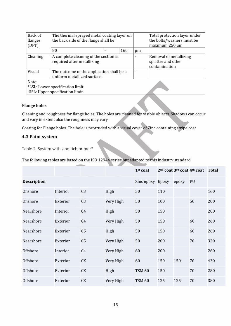
4.3 Paint system
Table 2. System with zinc-rich primer*
The following tables are based on the ISO 12944 series but adapted to this industry standard.
1st coat 2nd coat 3rd coat 4th coat Total
Description Zinc epoxy Epoxy epoxy PU
Onshore Interior C3 High 50 110 160
Onshore Exterior C3 Very High 50 100 50 200
Nearshore Interior C4 High 50 150 200
Nearshore Exterior C4 Very High 50 150 60 260
Nearshore Exterior C5 High 50 150
60 260
Nearshore Exterior C5 Very High 50 200 70 320
Offshore Interior C4 Very High 60 200
260
Offshore Exterior CX Very High 60 150 150 70 430
Offshore Exterior CX High TSM 60 150 70 280
Offshore Exterior CX Very High TSM 60 125 125 70 380

16
Table 3. System without zinc-rich primer*
1st coat 2nd coat 3rd coat 4th coat Total
Description Epoxy Epoxy Epoxy PU
Onshore * Interior C2 High 120 120
Onshore * Interior C2 Very High 200 200
Offshore Interior C2+dehumidifier Very high 200 200
Onshore Interior C3 High 50 130 Not used Not used 180
Onshore Exterior C3 High 130 Not used Not used 5 180
Nearshore Interior C4 High 100
140
240
Nearshore Exterior C5 High 100 150 Not used 50 300
Nearshore Exterior C5 Very High 150 150 Not used 60 360
Offshore Interior C3 + dehumidifier High 200 200
Offshore Interior C4 Very High 150 150 Not used Not used 300
Offshore Exterior CX Very High 250 250 Not used 60 560
Notes: *Zinc-rich primers, Zn (R), are those in which the zinc dust pigment content of the paint is equal to or greater than 80 % by mass in dry film For C2: Coat can be epoxy, PU or other 2 pack chemistry.
C2 can be chosen when a C2 environment is established either due to natural condition or climatic control
If only one coat of paint, then this must be performed by robots. Manual application, then two coats of paint are
required.
The list of paint systems are examples, deviations can occur.

17
5. Process for surface treatment of a wind turbine tower
5.1 Introduction The following chapter describes the process to be followed when a tower is surface treated and
painted.
5.2 Quality requirement for the substrate Substrate quality Construction steel: Rust grade A or B in accordance to ISO 8501-1. Edges Sharp edges and corners shall be rounded and smoothened by grinding to minimum radius 2 mm (1/10”) or by 3 pass chamfering. Defects in the steel surface It is the responsibility of the applicator to ensure that the components are suitable for surface treatment before and after abrasive blasting. Surface imperfections shall be removed from steel surfaces or dressed out in accordance with preparation grades in the following table.
Table 4. Preparation grades
Interpretation of imperfections according to ISO 8501-3 Description Preparation grades when C3 Preparation grades when C4, C5-
/CX Welds 1.1 Welding spatters
P2 Surface shall be free of all loose and lightly adhering welding spatter.
P3 Surface shall be free of all welding spatter.
1.2 Weld ripple/profile
P2 Surface shall be dressed to remove irregular and sharp-edged profiles (see figure 5 below).
P2 Surface shall be dressed to remove irregular and sharp-edged profiles.
1.3 Welding slag
P2 Surface shall be free from welding slag.
P3 Surface shall be free from welding slag.
1.4 Undercut
P2 Surface shall be free from sharp or deep undercuts.
P3 Surface shall be free from undercuts.
1.5 Weld porosity
P2 Surface pores shall be sufficient open to allow penetration of paint or dressed out.
P3 Surface shall be free from visible pores.
1.6 End craters
P2 End craters shall be free from sharp edges.
P2 End craters shall be free from sharp edges.
Edges 2.1 Rolled edges
P2 No preparation. P3 Edges shall be rounded with a radius of not less than 2 mm.
2.2 P2 No part of the edge shall be sharp; the edge shall be free from fins.
P3 Edges shall be rounded with a radius of not less than 2 mm.

18
Edges made by punching, shearing, sawing or drilling 2.3 Thermally cut edges
P2 No part of the edge shall have an irregular profile.
P3 Cut face shall be removed and edges shall be rounded with a radius of not less than 2 mm.
Surfaces generally 3.1 Pits and craters
P2 Pits and craters shall be sufficient open to allow penetration of paint or dressed out.
P2 Pits and craters shall be sufficient open to allow penetration of paint or dressed out.
3.2 Shelling
P2 Surface shall be free from visible shelling.
P3 Surface shall be free from visible shelling.
3.3 Roll overs/roll lamination/cut laminations
P2 Surface shall be free from visible roll-overs/laminations.
P3 Surface shall be free from visible roll-overs/laminations.
3.4 Rolled-in extraneous matter
P2 Surface shall be free from rolled-in extraneous matter.
P3 Surface shall be free from rolled-in extraneous matter.
3.5 Grooves and gouges
P2 The radius of grooves and gouges shall be not less than 2 mm.
P2 The radius of grooves and gouges shall be not less than 2 mm.
3.6 Indentations and roll marks
P2 Indentations and roll marks shall be smooth.
P2 Indentations and roll marks shall be smooth.
Irregularities in surfaces for paint application The applicator shall inform the Employer if any irregularities are observed e.g. faults in weld seams and surfaces, which may cause concerns regarding paint or strength related conditions. The quality leader must also be contacted and NCR actions shall be taken.
5.3 Preparation of the steel surface Pre-blasting preparations Foreign matter such as oil, grease, dirt, remains from NDT, weld flux, or other surface contamination shall be removed with suitable cleaning media and by washing with fresh water. The cleaning media and method used shall be accepted by the paint supplier. Salts and water-soluble impurities shall be removed by high pressure cleaning with freshwater. Particular care shall be taken on and around welds and areas which are difficult to access. The maximum content of soluble impurities on the blasted surface shall not exceed a conductivity measured in accordance with ISO 8502-9 corresponding to a NaCl content of maximum 50 mg/m2. Salt test shall be carried out before abrasive blasting on towers where risk of NaCl is present. 1 test per tower section. Blasting abrasives Blasting abrasives shall be dry, clean, and free from contaminants that are detrimental to the performance of the coating. For non-metallic abrasives ISO 11127-6 applies.

19
Size of abrasives particles for blast cleaning shall be such that the blast profile is in accordance with the requirements for the applicable coating system. Protection of threaded holes Before surface treatment all threaded holes shall be protected from abrasive blasting particles, paint, and metallization particles cf. the given specification. Abrasive blasting of steel surfaces prior to painting Abrasive blasting to cleanness level Sa 2½ according to ISO 8501-1 (SSPC SP10). The roughness shall, as a minimum, correspond with ISO COMPARATOR Medium (Grit) ISO 8503-1, Rz 60-100 µm. The blasting profile shall be sharp, dense, and uniform. Special attention shall be paid to achieve the correct blasting profile on weld seams and hard to reach areas. Remains of mill scale are not acceptable. Cleanness of surface prior to painting Moisture, particles from blasting, dirt and dust shall be removed before painting. Any shop primer for the offshore structure shall be fully removed from the surface by abrasive blasting. Onshore structures with shop priming only require sweep blasting. If used, the shop primer shall be of zinc ethyl silicate type and furthermore be accepted by the paint supplier prior to use. If the period of time between abrasive blasting and application results in a cleanness level which is lower than Sa 2½, then re-blasting to cleanness level Sa 2½ shall be performed. Abrasive blasting of areas prior to spray metallization Abrasive blasting shall be to cleanness level Sa 3 according to ISO 8501-1 (SSPC SP5). The roughness shall be in according with the ISO COMPARATOR level Coarse (Grit) ISO 8503-1, correspond to a roughness between 85 and 130µm in Rz-value. The surface shall be clean, dry, and free of visual corrosion products (oxides) during the entire metallization. The blasting profile shall be sharp, dense, and uniform. Special attention shall be paid to achieve the correct blasting profile on weld seams and hard-to-reach areas. Remains of mill scale are not acceptable. Cleanness of surface prior to spray metallization Moisture, particles from blasting, dirt and dust shall be removed before metallization. Any shop primer shall be fully removed from the surface by abrasive blasting. If the period of time between abrasive blasting and application results in a cleanness level which is lower than Sa 3, then re-blasting to cleanness level Sa 3 shall be performed. Ambient conditions and substrate temperature through surface treatment The substrate temperature shall be minimum 3°Celsius (6°F) above the dew point. The steel temperature during the blasting and metallization process shall be minimum 2 °C and the relative humidity shall be below 85 %. Paint shall only be applied at ambient temperatures according paint data sheet and steel temperatures above 10 °C. Preferably above 15°C. The relative humidity shall be lower than 85% RH and the ambient temperature shall as a minimum be 10°C. If recommendations from paint suppliers are stricter then the stricter requirements shall be met.
5.4 Surface treatment Thermally sprayed metallic Spray metallization in accordance with ISO 2063-1 and ISO 2063-2.

20
The metallizing material shall be type Zinc 100% or Zinc/Aluminum 85/15 % alloy in accordance with ISO 14919. All metallizing materials shall be supplied with product data sheets, certificates, and manufacturing data for the applicator. Tower flanges, flange welds, and shells at flange welds shall be spray metalized outside and inside, according to Figure 3 and 4. Door frame, door frame welds, and shells at door frame welds shall be spray metalized outside and inside, according to Figure 3 and 4. Internal and external brackets/clips and the bracket/clip welds shall be spray metalized before painting. If other layer thicknesses are specified by the drawings, then these have to be respected. Paint application For each coat, a stripe coat shall be applied by brush to manual welds, corners, around and on edges of brackets., and areas not fully reachable by spray to obtain the specified coverage and thickness. Stripe coat can also be done by spray metallization The brush application shall be done so that a smooth coat, as uniform in thickness as possible, is obtained. Roller application is not acceptable except for top coat repairs, this also applies for onsite repairs. Roller application is not allowed for primer layers (not including flange holes). Edges of existing coating shall be feathered towards the substrate prior to overcoat. Over coat and recoat intervals including other directions from the paint supplier shall be followed. Contamination of painted surfaces between coats shall be avoided. Any contamination shall be removed. Adjustment of paint by adding additives of any kind, apart from thinning with approved thinner type, is not accepted.
5.5 Paint system Layer thickness The layer thickness shall be measured and comply with ISO 12944-5 (5.4). Dry film thickness (DFT) and total dry film thickness (TDFT) shall be measured in according with ISO 12944-5, section 5.4. The measuring method and calibration shall be in according with ISO 2808.
For measurements of coatings on rough surfaces the ISO 19840 shall only apply upon agreement.
Smooth surfaces are used for calibration.
The number of measurements shall be in according with this standard, section 5.12, and ensure that:

21
▪ the arithmetic mean of all dry film thicknesses shall be equal to or higher than the specified
nominal dry film thickness (NDFT).
▪ all individual dry film thicknesses shall be equal to or above 80% of the NDFT.
▪ measurements between 80% of the NDFT and NDFT shall not exceed more than 20% of the
total number of individual measurements taken.
For offshore the 90-10 rule is required. For onshore the 80-20 rule is required.
Maximum system layer thickness is 3 times nominal dry film thickness. For each layer a maximum of 2 times the nominal layer thickness is allowed. Edge protection and flange holes Care shall be taken to avoid damaging edges after surface treatment Cleaning and roughness for flange holes The holes are cleaned for visible objects. Shadows can occur and vary in extent also the roughness may vary Coating for Flange holes The hole is protruded with a visual cover of Zinc Stripe coat
5.6 Over coating Coating intervals for metal surfaces Blasted and spray metallized surfaces which have to be surface treated shall be protected against contamination, corrosion and oxidation e.g. tarpaulins or humidity control. The cleanness specified in this specification is always to be met prior to metallization or paint application. Over coat intervals of metal surfaces can be extended by controlling the relative humidity of the ambient air or by over coating with a sealer (Mist coat). Mist coats do not count as a paint layer in the specified system. Stripe coating and repair application Stripe coating shall be applied by brush and carried out if areas difficult to access are not fully covered by airless spraying in order to secure the specified DFT. Repair work may be applied by brush as appropriate except for application of primer coat e.g. zinc primers and areas difficult to access, which shall be applied by brush. Follow repair procedure from paint supplier. Roller can be used only for cosmetic repairs. Coating intervals, paint system. The applicator shall verify that it is possible to comply with the surface treatment intervals specified by the paint supplier and that they are complied with. If the temperature conditions or layer thickness do not correspond with those specified by the paint supplier, then the paint supplier shall be contacted for alternative coating intervals. Curing time prior to handling and transportation. Until the system is fully cured it must not be subjected to permanent pools of water. Painted surface which has been subjected to permanent pools of water shall be sufficiently dried out in accordance to paint suppliers’ recommendation. In order to avoid damages on the paint system the paint shop shall ensure that the components are sufficiently cured prior to handling and transportation.

22
Pressure marks, scratch marks, or any other damages are not acceptable and shall be repaired. ‘Dry to handle’, ‘Dry to walk on’ and “Dry to wrap” shall be specified by the paint supplier of the paint system. Curing conditions in accordance with product data sheet. Data sheets and approvals. Technical Data Sheets, Safety Data Sheets and approval certificates shall be acquired from the paint supplier by the applicator for all the handle products.
5.7 Workshop, equipment, and workforce Workshop Pre-treatment, surface treatment, and drying/curing to be handled in an enclosed environment with controlled climatic conditions cf. data sheets. Paint products such as paint, hardener and thinner shall be kept in accordance with the data sheet for the paint system (Normal storage temperature 15-30 °C). Shelf life based on paint supplier information must be respected. The paint temperature during application should be between 15 and 25 °C, always though in accordance with the data sheet. Also, for the workshop temperature, see clause concerning dew point and steel temperature during application. The abrasive blasting and metallization area shall be isolated from the painting area. Non-conformance with this, shall require written acceptance from the employer. If abrasive blasting and metallization is conducted in the same area, it is required that the area is cleaned after abrasive blasting to prevent blasting remains from polluting the metallization work. Surface treatment and inspection work shall be conducted in sufficient light conditions, as a minimum 750 Lux [EN 12464-1, table 5.18.13] Equipment Suitable equipment shall be used for handling the job in an uninterrupted process and to avoid damages to the substrate at any time. The equipment shall be cleaned and maintained on a regular basis. External tower surfaces shall be painted while rotating. If equipment for rotation does not exist, then the painting process cannot proceed until the employer has approved the chosen method. Compressed-air facility shall be inspected continuously to ensure that no oil or water is contaminating the compressed air according to ASTM D 4285. Personnel Personnel shall be trained to have sufficient competence prior to commencement of any work in accordance to this specification.

23
5.8 Paint limitations Components and surfaces can be exposed to storage and transport conditions in which the environmental impact can be higher than as stated above. Such exposure shall be limited to short term, depending of type of exposure and recommendation by the paint supplier. Painted construction parts may not be exposed to moistures like rain and due within minimum 8 hours at min 20°C from application of the last coat. Other conditions will have to be agreed between the parties. Note different topcoats are available but have different recoating intervals and drying time before humid exposure. Consult the data sheet for the respective polyurethane topcoat. Painted construction parts shall not be immersed in water during curing. For fully cured paint systems immersion is not accepted for periods longer than 7 days. Painted surfaces which have been immersed in water shall be dried out by ventilation in air at humidity below 70 % RH.
▪ The paint shall be able to sustain the dynamic loads to which a turbine construction is exposed during normal operational conditions.
▪ High levels of UV radiation might occur. The paint system shall be resistant to oil and grease, only a requirement for continuous exposure to lubricants. Application method/stripe coating Brackets, door frame, and areas difficult to access shall be painted by stripe coating with brush before each spray coat of paint. A minimum of one stripe coat for the first layer is required. Covering of areas The assembly surfaces on flanges shall be covered to avoid being painted. Any paint on assembly surfaces shall be removed before delivery. After assembly of internals and cleaning of the tower, all openings shall be covered with necessary ventilation to avoid condensation. During transportation it must be ensured that no salt can enter the tower. Environment, health and safety The applicator shall ensure the health, safety, and welfare of his/her employees. National and local conditions regarding working environment, handling of refuse and safety, as well as legal environmental conditions, shall as a minimum be met.
5.9 Color and gloss Color Standard color externally: RAL 9010 (pure white) or RAL 7035 (light gray). Standard color internally: RAL 9001 (cream), 9010 (pure white) or RAL 7035 (light gray). If an alternative color is stated in the order the color in the order shall be used. Alternative inside color can be used if agreed to, in writing, by the customer. Contrasting colors shall be used for each coat of paint. Color pastes are not allowed. If applied by robots, deviations can be agreed by parties.

24
Gloss The external surface shall be smooth and homogenous. The recommended gloss level shall be semi glossy, 50-70 GU (Gloss units), when measured at an angle at 60° and according to ISO 2813:2014. Local requirement may occur. Color precision Tower sections may be paired randomly which means that no significant difference in the appearance of individual sections is accepted (Requirement: dE≤1), Color of topcoats by method: CMC (1:1) light source D 65 @ 10°), A or B, both in relation to defined shade and previously delivered batch for the actual project A) Deviations of light and grey shades from a tolerance of dE ≤ 1 B) Deviations of yellow and red shades from a tolerance of dE ≤ 2.5; with a and b values being positive. Gloss measurement and color measurement are not a part of standard quality inspection. Chalking UV resisting top coat is a requirement on external surfaces, hence chalking is not accepted. Minor chalking is accepted for internal epoxy coats if exposed to sun light during storage and transportation.
5.10 Quality control Quality plan The quality plan for surface treatment of components shall be made and available before production is begun. The quality plan shall as a minimum cover the following issues:
▪ Organization chart. ▪ People responsible for the job (Field of competence). ▪ Maintenance plan for essential equipment. ▪ References to the company’s internal QC system. ▪ Relevant time schedules. ▪ The people in the organization who releases surface for blasting, and when. ▪ The people in the organization who releases surface for painting. ▪ The people in the organization who performs final inspection and approval of layer thickness
and application quality. ▪ Handling, approval, and documentation of corrective action in case of irregularities (Including
the people in the organization who have authorization to sign for e.g. steel inspection, paint inspection, and final inspection).
As an alternative to the above quality plan, the supplier may present a process instruction which drafts the work process. The Process instruction shall be made and approved by to employer quality department, before production is begun. It should be noted that a released quality manual or process instruction does not relieve the supplier of the responsibility for the delivered product. Acceptance check It is the responsibility of the applicator, upon receipt, to check the condition of the component and its suitability for surface treatment.

25
Final inspection Components delivered are not considered received until all documents have been received by customer.
5.11 Inspection Inspection plan Control is carried out as process control. A log shall be made (Control report) for the full surface treatment process. The control is made in accordance with the released quality manual. In addition, the following shall be reported:
▪ Surface check (Ensure that all surface areas are suitable for surface treatment. ▪ Temperature. ▪ Dew point. ▪ Start and finish time for abrasive blasting. ▪ Start and finish time for painting and metallization. ▪ Quality, gloss, and batch number. ▪ Layer thicknesses. ▪ Curing time and average curing temperature. ▪ Repairs with additional paint or metallization layers. ▪ Drawing number and revision number.
Repairs with additional paint or metallization layers shall be documented through an Non-Conforming-Report with traceability to the individual reparation, on the relevant drawing from customer. Inspection method Visual control of the entire component is required after surface treatment. It shall be ensured that the following is not found:
▪ Blisters and / or sweating during curing. ▪ Pinholes*. A few pinholes can be repaired with paint. ▪ Dry spray and spray dust. ▪ Holidays, runs or sagging on surfaces and in bolt holes. ▪ Paint on flange surfaces that are to be metallized only. ▪ Noticeable color variations on the external surfaces. ▪ Scratches, pressure marks, and other damages from production handling and transportation. ▪ Dust and dirt in the paint.
*) As a rule, no pinholes are accepted. A few pinholes, 5 pr. m² or less, in the external paint film on thermal spray metalizing surfaces will be accepted if closed by a drop of paint. A few pinholes on the internal surfaces will be accepted without repair, provided that no voltage leaks have been detected, according to ISO 29601 For all surfaces it is required that areas with dense pore formation and serial pore shall be repaired. Check measurements shall be made on the full scope of delivery. The layer thickness shall be measured and comply with the percentage requirement stated cf. ISO 12944-5 (5.4). If this requirement is not fulfilled it will be considered as a nonconformity and treated as such.

26
Minimum 1 reading per 2 m² and 1 m running edge shall be performed. The readings shall be distributed randomly over the entire surface. If >20% of the readings are between the percentage requirement and the specified value, then 1.5 readings per 2 m² shall be performed. Equipment for check measurement of the abrasive blasted surface and layer thickness measurements shall be calibrated routinely on reference objects. Inspection by applicator It is the responsibility of the applicator to perform the inspection in accordance with the requirements in this specification, if necessary incorporate them into the company’s own quality plan. Inspection by employer The employer reserves the right to inspect production and documentation of components at any time.
5.12 Documentation Registration It is the responsibility of the applicator to produce a control report for documentation of the application work and the conducted quality control process. 3.1-EN 10204 inspection document. Paint product qualifications The paint supplier shall be able to document product test and approval in accordance with ISO 12944 part 6 for the chosen paint system. Paint supplier Supply and trade agreement between employer and paint supplier shall be completed before paint products can be accepted for application. Certificates and batch numbers Certificate and batch numbers shall be noted in the documentation to ensure full traceability Top coat and batch numbers The paint supplier shall be able to verify by batch certificates that the color tolerance is at same level, thereby avoiding unacceptable color variation.
5.13 Handling and storage
Handling By using suitable auxiliary tools (Protected handling brackets, suitable lifting brackets, storage stands etc.) the applicator shall ensure an appropriate handling which does not cause damage to the components, both before and after surface treatment Transport handling shall be performed in a way which will ensure that no damage is caused to the construction parts or painted / metallized surfaces Slings are not allowed on painted or metallized surfaces without prior agreement with the employer. Storage

27
In case components are stored e.g. on wooden beams, the painted surface shall be protected by heavy duty plastic sheets only to be mounted when the painting is fully cured. The plastic sheets shall be placed against the painted or metallized surface The components shall be stored in a way that ensures the protection from pressure marks in the surface treatment. Dehumidifier: If dehumidifier is used special precautions need to be made during transport and
storage as interior needs to be kept dry at all times.
Delivery When handing over to the employer the components shall be cleaned to remove dust, dirt, mud, oil, grease, or other contamination. If there is a risk that the painted surface will be polluted by iron dust (“Fly rust”) from abrasive blasting or adjacent steel works, the tower shall be washed with a suitable form of rust particle remover in accordance with the paint supplier’s instruction. The cleaning shall be performed immediately before the component is picked up for transportation. The tower sections shall be cleaned/ washed inside before delivery for mounting of internal components, and outside before delivery for transportation. Cleaning shall not damage assembled components.
5.14 Repair of paint system
Any damage to the paint layers shall be repaired before delivery. Paint for repair of damages shall be approved by the supplier of the paint system to be repaired. The paint supplier’s procedure is to be followed Repair area Only minor repair on the tower are accepted after leaving the workshop. Minor repair is determined as a total repaired area below 2 square meters. The repair may be divided into 5 local areas with a total area smaller than 2 square meters. Scattered repair areas are not allowed. If any repair work is needed on the exterior surface of the two lower shell plates on bottom tower section (Minimum 3 meter), the entire damage shell shall be repainted. A few pinholes can be repaired without re-painting. A repaired surface shall be smooth and even with a quality level equal to the sound layer of paint surrounding the repair area. Repairs in the top coat shall have two weld seams as borders and have a square shape with straight sides. Areas with weld repair work i.e. replacement of brackets, shall be re-blasted and reapplied the full coating system on both the external and internal tower surface located in the heat zone. The repair work is to include overlapping into sound system.

28
5.15 Nonconformity Managing non-conformities Nonconformities shall be treated systematically. Qualitative nonconformity Nonconformities in relation to quality requirements in the individual work phases shall be resolved between the phases. Nonconformities in relation to the quality requirements of this specification will not be accepted and shall be resolved before delivery to customer.
5.16 Paint performance Defects related to paints and paint systems performance The following occurrences caused by a failure of a coating product or an error in the coating application process or product requirement are considered as Defects. The list is not exclusive and is not meant to limit Defects of certain categories or types listed elsewhere in the specification.
Defects related to paints and paint systems on Towers occur if they affect an area covering more than 0.1% of the total area of the respective tower coating system or a total weld length of 2m or more and one of the following failures occur within 66 months after takeover of the WTG-Components by the Employer:
▪ Blistering has broken the coating down to an extent exceeding or similar to 1 (S2) (according to ISO 4628-2), or
▪ Rusting has broken the coating down to an extent exceeding or similar to Ri 1 (according to ISO 4628-3), or
▪ Cracking has broken the coating down to an extent exceeding or similar to 1 (S2) (according to ISO 4628-4), or
▪ Flaking has broken the coating down to an extent exceeding or similar to 1 (S2) (according to ISO 4628-5).

29
Bibliography
ISO 8502-3:2017, Preparation of steel substrates before application of paints and related products –
Tests for the assessment of surface cleanliness – Part 3: Assessment of dust on steel surfaces prepared for
painting (pressure-sensitive tape method)
ISO 4628-1:2016, Paints and varnishes – Evaluation of degradation of coatings – Designation of quantity
and size of defects, and of intensity of uniform changes in appearance – Part 1: General introduction and
designation system
ISO 12944-3:2017, Paints and varnishes -- Corrosion protection of steel structures by protective paint
systems -- Part 3: Design considerations
ISO 12944-4:2017, Paints and varnishes -- Corrosion protection of steel structures by protective paint
systems -- Part 4: Types of surface and surface preparation
ISO 12944-7:2017, Paints and varnishes -- Corrosion protection of steel structures by protective paint
systems -- Part 7: Execution and supervision of paint work
ISO 12944-8:2017, Paints and varnishes -- Corrosion protection of steel structures by protective paint
systems -- Part 8: Development of specifications for new work and maintenance