wind turbine design guideline technical report
TRANSCRIPT

Technical Report NREL/TP-500-42362 December 2009
Wind Turbine Design Guideline DG03: Yaw and Pitch Rolling Bearing Life T. Harris J.H. Rumbarger C.P. Butterfield

National Renewable Energy Laboratory 1617 Cole Boulevard, Golden, Colorado 80401-3393 303-275-3000 • www.nrel.gov
NREL is a national laboratory of the U.S. Department of Energy Office of Energy Efficiency and Renewable Energy Operated by the Alliance for Sustainable Energy, LLC
Contract No. DE-AC36-08-GO28308
Technical Report NREL/TP-500-42362 December 2009
Wind Turbine Design Guideline DG03: Yaw and Pitch Rolling Bearing Life T. Harris J.H. Rumbarger C.P. Butterfield
Prepared under Task No. WE101131

NOTICE
This report was prepared as an account of work sponsored by an agency of the United States government. Neither the United States government nor any agency thereof, nor any of their employees, makes any warranty, express or implied, or assumes any legal liability or responsibility for the accuracy, completeness, or usefulness of any information, apparatus, product, or process disclosed, or represents that its use would not infringe privately owned rights. Reference herein to any specific commercial product, process, or service by trade name, trademark, manufacturer, or otherwise does not necessarily constitute or imply its endorsement, recommendation, or favoring by the United States government or any agency thereof. The views and opinions of authors expressed herein do not necessarily state or reflect those of the United States government or any agency thereof.
Available electronically at http://www.osti.gov/bridge
Available for a processing fee to U.S. Department of Energy and its contractors, in paper, from:
U.S. Department of Energy Office of Scientific and Technical Information P.O. Box 62 Oak Ridge, TN 37831-0062 phone: 865.576.8401 fax: 865.576.5728 email: mailto:[email protected]
Available for sale to the public, in paper, from: U.S. Department of Commerce National Technical Information Service 5285 Port Royal Road Springfield, VA 22161 phone: 800.553.6847 fax: 703.605.6900 email: [email protected] online ordering: http://www.ntis.gov/ordering.htm
Printed on paper containing at least 50% wastepaper, including 20% postconsumer waste

i
Foreword
This document is part of a series developed by the National Renewable Energy Laboratory, National Wind Technology Center. These guidelines are intended to be a design aid for wind turbine designers. The complete list of guidelines is provided below.
• DG01 Loads Analysis
• DG02 Strength Analysis
• DG03 Yaw and Pitch Rolling Bearing Life Design Guideline
• DG04 Gearbox Specification
• DG05 Control and Protection System Specification and Design
All of these documents—with the exception of the present document (DG03)—are in draft form and are available only by request sent to NREL, [email protected].
Modern wind turbines use large turntable bearings at the root of each blade to enable pitch angle changes and thus aerodynamic performance and load control. Yaw bearings are used for angular realignment of the nacelle into the predominant wind direction. These applications require long periods in nearly stationary positions with large stochastic loads. Due to this demanding load environment and the fact that bearings exist in the critical load path, their design becomes critical to the safety and reliability of most turbine designs.
This document attempts to introduce modern bearing-design practice and its relation to the unique requirements of wind turbine applications. The fundamental theory presented here is available in other textbooks referenced in this document, and included in the References section found at the end of this report.
First drafted in 1999 by John Rumbarger, this document was reviewed and updated extensively by Tedric Harris in 2008, and later in 2008 it was reviewed and edited by Bob Errichello.
Sandy Butterfield, Chief Engineer NREL Wind Program
November 10, 2008

ii
List of Acronyms
DEH Distortion Energy Hypothesis FEA finite element analysis kNm Kilo Newton-Meters MPa Mega Pascals opm oscillations per minute rms root-mean-square rpm rotations per minute TDC thin dense chrome

iii
Contents
List of Figures ................................................................................................................................ v List of Tables ................................................................................................................................. v 1. Introduction ............................................................................................................................... 1 2. Yaw and Pitch Rolling Bearing Design Types ........................................................................ 1 3. Summary of Calculation Methods ........................................................................................... 3
3.1. General ................................................................................................................................. 3 3.2. American National Standard Method .................................................................................. 3 3.3. International Standard Method ............................................................................................ 4 3.4. Stress-Life Method............................................................................................................... 4 3.5. Bearing Design Criteria ....................................................................................................... 4
4. Calculation of Bearing Fatigue Life ........................................................................................ 5 4.1. Lundberg-Palmgren Theory ................................................................................................. 5 4.2. Applied Loading .................................................................................................................. 5 4.3. Basic Dynamic Axial Load Rating ...................................................................................... 5 4.4. Dynamic Equivalent Axial Load ......................................................................................... 7 4.5. Bearing L10 Life ................................................................................................................... 8
4.5.1. Basic L10 Life Equations ............................................................................................... 8 4.5.2. ANSI/ABMA Standard Modified Rating Life ............................................................. 9
4.5.2.1. Life Modification Factor for Reliability ................................................................ 9 4.5.2.2. Life Modification Factor for Material .................................................................. 10 4.5.2.3. Life Modification Factor for Lubrication ............................................................ 10 4.5.2.4. Life Modification Factor for Flexible Supporting Structure ................................ 11 4.5.2.5. Life Calculation for Oscillating Bearings ............................................................ 12 4.5.2.6. False Brinelling and Fretting Corrosion .............................................................. 13
4.5.3. ISO Standard Life ....................................................................................................... 15 4.5.4. Stress-Life Method ..................................................................................................... 16
5. Bearing Static Capacity .......................................................................................................... 18 5.1. Permanent Deformation ..................................................................................................... 18 5.2. Maximum Ball or Roller Load ........................................................................................... 18 5.3. Maximum Contact Stress ................................................................................................... 18 5.4. Contact Dimensions ........................................................................................................... 19
5.4.1. Point Contact .............................................................................................................. 19 5.4.2. Line Contact ............................................................................................................... 20
5.5. Static Load Factor .............................................................................................................. 22 5.6. Effect of Surface Hardness on Static Capacity .................................................................. 23
6. Estimation of the Case-Core Interface Depth ...................................................................... 23 6.1. Design Stresses .................................................................................................................. 23 6.2. Allowable Shear Stresses for Yield and Fatigue ................................................................ 24 6.3. Calculation of Subsurface Shear Stress ............................................................................. 25 6.4. Evaluation of the Case-Core Interface ............................................................................... 26
7. Effective Lubrication .............................................................................................................. 27 8. Bearing Friction Torque......................................................................................................... 28

iv
9. Miscellaneous Design Considerations ................................................................................... 28 9.1. General ............................................................................................................................... 28 9.2. External Bolting ................................................................................................................. 28 9.3. Cages or Separators............................................................................................................ 28 9.4. Integral Seals ...................................................................................................................... 29
Nomenclature .............................................................................................................................. 30 References .................................................................................................................................... 32 Appendix A. Wind Turbine Yaw Bearing ................................................................................ 33
A.1. Operating Conditions and Bearing Dimensions................................................................ 33 A.2. Dynamic Equivalent Loads ............................................................................................... 34 A.3. Basic Dynamic Axial Load Rating ................................................................................... 35 A.4. Basic L10 Life .................................................................................................................... 35 A.5. Modified L10 Life According to ANSI/ABMA Standard 11 ............................................. 35 A.6. Modified L10 Life According to ISO Standard 281 ........................................................... 36 A.7. Modified L10 Life According to Stress-Life Method ........................................................ 37 A.8. Maximum Roller Load ...................................................................................................... 38 A.9. Contact Semi-Width, Hertz Stress, and SF ....................................................................... 38 A.10. Case-Core Interface......................................................................................................... 39 A.11. Evaluation for Potential Fretting Corrosion .................................................................... 40 A.12. Lubricant and Lubrication ............................................................................................... 40 A.13. Bearing Friction Torque .................................................................................................. 40 A.14. Design Summary ............................................................................................................. 41
Appendix B. Wind Turbine Pitch Bearing ............................................................................... 42 B.1. Operating Conditions and Bearing Dimensions ................................................................ 42 B.2. Bearing Dynamic Equivalent Loads and Speeds .............................................................. 43 B.3. Bearing Basic Dynamic Axial Load Rating for Rotation ................................................. 44 B.4. Basic Dynamic Axial Load Rating for the Oscillating Bearing ........................................ 45 B.5. Basic L10 Life .................................................................................................................... 45 B.6. Modified L10 Life According to ANSI/ABMA Standard 11 ............................................. 45 B.7. Modified L10 Life According to ISO Standard 281 ......................................................... 47 B.8. Modified L10 Life According to Stress-Life Method ........................................................ 48 B.9. Maximum Ball Load ......................................................................................................... 48 B.10. Contact Ellipse Dimensions ............................................................................................ 49 B.11. Hertz Contact Stress and Static Load Factor ................................................................... 50 B.12. Case–Core Interface ........................................................................................................ 50 B.13. Hertz Stress Limits for Avoidance of Fretting Corrosion ............................................... 51 B.14. Dither Angle .................................................................................................................... 52 B.15. Lubrication ...................................................................................................................... 52 B.16. Friction Torque ................................................................................................................ 52 B.17. Miscellaneous .................................................................................................................. 53 B.18. Summary ......................................................................................................................... 53

v
List of Figures
Figure 1. Yaw and pitch bearing types (eight-point contact ball bearing, four-point contact ball bearing, cross roller (x) bearing) ............................................................................................ 2
Figure 2. Pitch bearing coordinates and loads ................................................................................ 3Figure 3. Application of loads for a single-bearing system ............................................................ 7Figure 4. Amplitude angle for one cycle of oscillation ................................................................ 12Figure 5. Schematic of two solid elastic curved bodies (Body a, Body b)
compressed by load Q .......................................................................................................... 19Figure 6. Radii of curvature for a four-point contact ball bearing ................................................ 21Figure 7. Typical subsurface shear stress curve ............................................................................ 24Figure 8. Allowable subsurface shear stresses .............................................................................. 25Figure 9. Subsurface shear stress parameter versus z/b and b/a (Curve A: b/a = 0; B: b/a = 0.1; C:
b/a = 0.2; D: b/a = 0.3; E: b/a = 0.4; F: b/a = 0.5) ............................................................... 26Figure A-1. Yaw bearing coordinates and loads ........................................................................... 33Figure B-1. Pitch bearing coordinates and loads .......................................................................... 42Figure B-2. Four-point contact ball bearing ................................................................................. 43Figure B-3. Eight-point contact ball bearing ................................................................................ 46
List of Tables
Table 1. Values of fcm for Yaw and Pitch Ball Bearings fi = fo = 0.53 ............................................ 6Table 2. Values of fcm for α = 45° Yaw and Pitch Roller Bearings ................................................ 7Table 3. Life Modification Factor a1 for Reliability ....................................................................... 9Table 4. Life Modification Factor a2 for Material Hardness ........................................................ 10Table 5. Life Modification Factor a4 for Flexible Support Structure ........................................... 12Table 6. Constants and Exponents for Thrust Bearings (Using Equation 24) .............................. 16Table 7. Constants c1 and c2 Versus Contamination Level ........................................................... 16Table 8. Mises Fatigue Limit Stress (ΦVM,lim ) for Various Steels ............................................... 17Table 9. Maximum Hertz Stress (Permanent Deformation = 0.0001D) ....................................... 18Table 10. Values a* and b* Versus F(ρ) ...................................................................................... 21Table 11. Curvatures for a Four-Point Contact Ball Bearing ....................................................... 22Table 12. Curvatures for a Cylindrical Cross Roller Bearing ....................................................... 22Table 13. Hardness Reduction Factor fs Versus Hardness ............................................................ 23Table 14. Allowable Subsurface Shear Stresses ........................................................................... 25Table 15. Subsurface Shear Stress Parameter Versus z/b and b/a ................................................ 26Table 16. Hertz Stress Limits to Minimize Fretting Corrosion Failures in Yaw and
Pitch Bearings ....................................................................................................................... 27Table 17. Bearing Friction Coefficient μ Versus Bearing Type ................................................... 28Table A-1. Yaw Bearing Load Duty Cycle .................................................................................. 33Table A-2. Yaw Bearing Dimensions and Material Properties .................................................... 34Table A-3. Yaw Bearing Dynamic Equivalent Axial Loading for the Duty Cycle ...................... 34Table A-4. Qmax for Equivalent and Limit Loads ......................................................................... 38Table A-5. Qmax for Equivalent and Limit Loads ......................................................................... 39

vi
Table A-6. Comparison of Calculated Hertz Stresses with Recommended Limit Stresses to Avoid Fretting in Bearing Raceways ................................................................................... 40
Table A-7. Bearing Friction Torque for Average and Limit Loads .............................................. 40Table B-1. Bearing Duty Cycle Speeds and Loads ....................................................................... 42Table B-2. Four-Point Ball Bearing Dimensions and Material Properties ................................... 43Table B-3. Bearing Dynamic Equivalent Axial Loads over the Duty Cycle ................................ 43Table B-4. Eight-Point Ball Bearing Dimensions and Material Properties .................................. 46Table B-5. Qmax for Equivalent and Limit Loads .......................................................................... 49Table B-6. Comparison of Calculated Hertz Stresses with Recommended Limit Stresses to Avoid
Fretting in Bearing Raceways .............................................................................................. 51Table B-7. Bearing Friction Torque for Operating and Limit Loads ........................................... 52

1
1. Introduction
This report describes the design criteria, calculation methods, and applicable standards recommended for use in performance and life analyses of ball and roller (rolling) bearings for yaw and pitch motion support in wind turbine applications. The formulae presented here for rolling bearing analytical methods and bearing-life ratings are consistent with methods in current use by wind turbine designers and rolling-bearing manufacturers. Methods for determining the loads and moments to be used for rating yaw and pitch bearings are covered in a separate design guide, available upon request from [email protected].
National Renewable Energy Laboratory (NREL) Guideline DG03 can be used with relevant standards and guidelines either for designing yaw and pitch rolling bearings for wind turbines or for verifying a design. This guideline provides a method for estimating the life of yaw and pitch rolling bearings used in wind turbines and gives general recommendations for enhancing bearing life in these applications.
2. Yaw and Pitch Rolling Bearing Design Types
Large wind turbines (those rated at more than 250 kW) use ball or roller bearings with special configurations for blade retention pitch bearing and yaw bearing locations. Three common bearing configurations are shown in Figure 1. The bearings consist of two ring-rolled forgings forming the outer and inner raceways and a complement of either balls or rollers. The inner and outer continuous-ring forgings have mounting holes that allow the bearing to be bolted directly to the supporting structures. The balls or rollers are inserted into the bearing through a radial cylindrical hole in one of the rings. The hole then is closed using a removable loading plug con-toured to the ball path or roller path surface. The three bearing types shown in Figure 1 have two distinct thrust load paths and can carry simultaneous radial, axial, and overturning moment loads.
It is common practice to cut a spur gear integral with one of the bearing rings, especially for the yaw bearing application. A detailed cross-sectional sketch and cutaway sketch of a four-point con-tact ball bearing is shown in Figure 1. Individual plastic spacers or thin section cage arc segments are used to separate the balls. The spacers are cylindrical with a hemispherical end (not shown in Figure 1). The individual rollers in the cross-roller bearing are separated by plastic, saddle-shaped spacers. The rollers in the cross-roller bearing alternate in their orientation to carry load.
The inner and outer rings are hardened from 250 to 300 Brinell hardness (HB). This is referred to as the “core hardness” of the ring. This core hardness should provide adequate core yield and fatigue strength, yet remain at a hardness low enough to facilitate machining of the rings, gear teeth, and mounting-bolt holes. The actual ball or roller path (rolling contact surface) is induction heated, quenched, and tempered to provide a hard surface or “case.” The surface hardness of the raceway is a minimum of 58 HRC (Rockwell C scale hardness). The depth of the hardened case is defined as the depth to a hardness of 50 HRC.
The four-point contact ball bearing type shown in Figure 1 consists of a single row of balls separated by cage segments or plastic spacers. The ball groove configuration is that of a gothic arch, which provides two distinct thrust load paths for each ball. The eight-point contact ball bearing type shown in Figure 1 is similar, but it has two rows of balls in gothic arch ball grooves.

2
The two-row, eight-point contact ball bearing type is more costly to manufacture than the single-row, four-point contact ball bearing. In addition to having a second row of balls and separators, the two-row bearing must be repeatedly assembled and disassembled during manufacture to accurately measure and match the internal diametral clearance or preload of the two ball rows.
The main advantages of the eight-point contact ball bearing, as compared to the four-point contact ball bearing, are:
• Lower ball loads;
• Lower Hertz stresses;
• Less required case depth; and
• Increased fatigue life.
Figure 1. Yaw and pitch bearing types (eight-point contact ball bearing, four-point contact ball bearing, cross roller (x) bearing)

3
Figure 2. Pitch bearing coordinates and loads
3. Summary of Calculation Methods
3.1. General The method for estimating rolling bearing fatigue life in wind turbine yaw and pitch applications is based on—and similar to—the equations and procedures provided in the International Standards and American National Standards (1–4) for load and life ratings. It basically involves five steps:
1. Calculating the dynamic load rating for the bearing; 2. Calculating life adjustment factors for the application; 3. Determining the rolling element–raceway load at each rolling element angular location; 4. Calculating the dynamic equivalent load; and 5. Using the values to calculate the bearing fatigue life.
3.2. American National Standard Method The dynamic load rating for the bearing can be obtained from a bearing manufacturer’s catalog or it can be calculated using the equations presented in this guide; these equations are examined in detail by Harris and Kotzalas [5]. Fatigue life then is calculated according to American National Standards Institute/American Bearing Manufacturers Association (ANSI/ABMA) Standard 9 [3] for a ball bearing or ANSI/ABMA Standard 11 [4] for a roller bearing. The standard life rating model then is modified for application to oscillating bearings. This modification also is supplied in Harris & Kotzalas [5].

4
Life adjustment factors for bearing material, lubrication, and contamination, described by Zaretsky [6] and given in Harris & Kotzalas [5], can be applied to wind turbine yaw and pitch bearings discussed in this guide. For a bearing subjected to combined radial, axial, and moment loading, as indicated in Figure 2, a dynamic equivalent load must be used to determine life. Further, if the applied loads and speeds vary over the length of time that the bearing operates, then an equivalent load also must be determined. Equations to calculate equivalent loads are presented in Harris & Kotzalas [5] and also are supplied in this guide.
The foregoing method is presented here. It is expected, however, that this eventually will be superseded by the International Standard method.
3.3. International Standard Method After the dynamic load rating for the bearing is obtained from the bearing manufacturer’s catalog or calculated using the equations provided in this report, fatigue life then is calculated according to ISO Standard 281 [1] for either a ball or roller bearing. A single, integrated life adjustment factor, designated aISO, then is calculated according to the methods shown in ISO Standard 281 [1] and provided in detail in Harris & Kotzalas [5]. The use of this method requires the input of a fatigue limit load (Pu); this parameter generally is given in bearing manufacturers’ catalogs.
3.4. Stress-Life Method The stress-life method of fatigue life calculation is similar to the ISO Standard 281 method in that it employs an integrated life adjustment factor, aSL. Included in the determination of aSL is a fatigue limit stress ΦVM,lim based on the Von Mises stress criterion. This is a different stress than that used by the other methods, which are based on the maximum orthogonal shear stress τ0 as the failure criterion. In determining aSL, all conditions that influence fatigue endurance are converted to stresses and added as vectors to create the Von Mises stress at each point in the stressed material. The Von Mises stress at each subsurface and surface point is compared against ΦVM,lim to determine the possibility and probability of fatigue failure. The stress-life method is explained in detail in Harris and Kotzalas [5] and also in Barnsby et al. [7].
3.5. Bearing Design Criteria The proper design of a yaw or pitch bearing must satisfy five design criteria and the miscellaneous considerations listed below. Each of the following criterion is addressed in detail in this guide.
1. Bearing fatigue life (rolling contact fatigue) 2. Bearing static capacity 3. Adequate case depth and core hardness 4. Adequate lubrication (surface failure) 5. Friction torque 6. Miscellaneous
A. External bolting B. Cages or separators C. Integral seals
The relationships used in the method for determining the basic dynamic capacity in oscillation, life adjustment factors, and equivalent load are supplied in Section 4.

5
4. Calculation of Bearing Fatigue Life
4.1. Lundberg-Palmgren Theory In general, the method for demonstrating adequate life for rolling bearings is to use mathematical models to estimate the minimum life. For rolling bearings this typically is done using a model proposed by Lundberg and Palmgren [8, 9]. The Lundberg-Palmgren theory forms the basis of ISO Standard 281 [1], ANSI/ABMA Standard 9 and Standard 11 [3, 4], and the stress-life method [7]. Discussion of the Lundberg-Palmgren model as it can be applied using the ANSI/ABMA standards [3, 4], and the determination of coefficients and material factors are summarized in Rumbarger and Poplawski [10].
The Lundberg-Palmgren theory and its derivative methods determine rolling contact fatigue life according to the statistical probability of the survival of a bearing; the probability of failure is the complement of probability of survival. Bearing life L is expressed in terms of millions of revolutions of the rotating raceway. The usual industry practice is to specify bearing life according to a 10% probability of failure, or L10. L10 also can be expressed in hours of operation. The Lundberg-Palmgren model refers to the visible evidence of rolling contact fatigue of the raceway surfaces. Although rolling elements (i.e., balls, rollers) also could fail, the Lundberg-Palmgren theory does not accommodate that phenomenon. Derivative methods, based on Lundberg-Palmgren (e.g., Barnsby et al. [7]), include the probability of rolling element failure.
Actual operational failure (ceasing to rotate satisfactorily) of a yaw or pitch bearing occur after the accumulation of damage. In some applications, this increased time or life margin can equal or exceed the L10 life. A periodic oil or grease analysis can be helpful in determining the approach of a field failure.
The life model is based on a consideration of the stressed volume of material in a ball-raceway or a roller-raceway contact and the number of stress repetitions. This method has been extended and used in life rating of oscillating rolling bearings; see Harris and Kotzalas [5].
4.2. Applied Loading Ball and roller bearings used for wind turbine yaw and pitch bearings, as shown in Figure 1, are thrust-type bearings. The principal load is an eccentrically applied thrust which results in an axial load and an overturning moment load. The distribution of the applied load to the individual balls or rollers is predominantly one of thrust, where the number of loaded elements is greater than one-half. Ideally, the radial load is distributed over half (or fewer) of the rolling elements. Applied simultaneously with thrust and overturning moment loads, radial load affects the thrust type of load distribution but does not significantly alter it.
4.3. Basic Dynamic Axial Load Rating Basic dynamic axial load rating, or thrust basic dynamic capacity, is defined as the constant centric thrust load that a rolling bearing theoretically could endure for a rating life (L10) of 1 million revolutions. The load rating standards [1, 3, 4] provide the following formula for a basic dynamic axial load rating for thrust ball bearings.
( ) αα tancos 8.13/27.0 DZifC cma = (1)

6
The material factor fcm based on CVD 52100 steel material is given in Table 1. Compared with the values given in the standards [1, 3], these values have been extrapolated to accommodate large-diameter bearings (i.e., γ values to 0.002, γ = Dcosα/dm). Because standard values of factor fcm are based on a raceway groove conformity of 0.52 (f = raceway groove curvature radius/D), and because yaw and pitch ball bearings frequently have a 0.53 conformity, Table 1 presents values of fcm adjusted for the latter ball-raceway conformity. To obtain fcm for 0.52 conformity, the fcm values of Table 1 must be multiplied by 1.172.
Table 1. Values of fcm for Yaw and Pitch Ball Bearings (fi = fo = 0.53)
γ fcm (α = 45°) fcm (α = 60°) 0.002 28.84 26.84 0.004 35.50 33.05 0.006 40.09 37.32 0.008 43.69 40.67 0.010 46.70 43.48 0.020 57.35 53.35 0.030 64.56 60.12 0.040 70.21 65.33 0.050 74.48 69.44 0.060 78.42 72.99 0.070 85.53 75.87 0.080 84.19 78.31 0.090 86.52 80.53 0.100 88.40 82.30
The equations for the basic dynamic axial load rating, Ca, depend on the ball diameter. According to the load rating standards [1, 3], the capacity is reduced for balls larger than 25.4 mm (1 in.), as indicated in equation 2.
( ) αα tancos647.3 4.13/27.0 DZifC cma = (2)
For thrust roller bearings, the load rating standards provide the following equation for basic dynamic axial load rating.
( ) αα tancos 27/294/39/7 DZlfC ecma = (3)
The fcm values for thrust roller bearings are given in Table 2. Compared with the values provided in the standards [1, 4], these values have been extrapolated to accommodate large-diameter bearings (i.e., γ values to 0.002, γ = Dcosα/dm).

7
Table 2. Values of fcm for α = 45° Yaw and Pitch Roller Bearings
γ fcm 0.001 66.36 0.002 77.41 0.004 90.30 0.006 98.81 0.008 105.32 0.010 110.65 0.020 128.91 0.030 140.76 0.040 149.60 0.050 156.61 0.060 162.32 0.070 167.07 0.080 171.03 0.090 174.35 0.100 177.12
4.4. Dynamic Equivalent Axial Load A typical load application is shown in Figure 3. Radial (Fr), thrust (Fa), and overturning moment (M) loads are shown as applied to the center of the bearing coordinate system. The radial and moment loads sometimes are given as orthogonal vectors. The root-mean-square (rms) values of the two orthogonal components then are used to determine the magnitude of Fr and M. The dynamic equivalent axial load (Pea) is defined as a constant centric (uniformly distributed) axial load; under whose influence a rolling bearing would have the same life as it would attain under the actual load conditions.
Figure 3. Application of loads for a single-bearing system

8
The equivalent axial load (Pea) also is defined in terms of the individual ball or roller loads (Qj) [5], where the subscript j refers to the angular location of the rolling element about the bearing axis. The following is for ball bearings.
αsin13/1
1
3 ZQZ
PZj
jjea
= ∑
=
=
. (4)
In equation 4, Z equals the total number of balls in the bearing (whether loaded or not loaded). The following equation is for cross-roller bearings.
αsin14/1
1
4 ZQZ
PZj
jjea
= ∑
=
=
. (5)
In equation 5, Z equals the number of rollers oriented to carry thrust load in one direction (whether loaded or not loaded). The dynamic equivalent thrust load also can be estimated from the applied loads as follows.
marea d
MFFP 275.0 ++= (6)
4.5. Bearing L10 Life 4.5.1. Basic L10 Life Equations The life of an individual bearing is defined as the number of revolutions one of the bearing rings (or raceways) makes in relation to the other ring (or raceway) before the first evidence of fatigue develops in the material of one of the rings (or raceways) or rolling elements. For thrust ball bearings, the L10 life, expressed in millions of revolutions, is given by the following.
3
10
=
ea
a
PC
L (7)
For thrust roller bearings the following is used.
3/10
10
=
ea
a
PCL (8)
L10 life also can be determined in hours of operation, as follows, where speed N is in rpm.
6010)(
610
10 ⋅⋅
=N
LhrL (9)

9
The prorated bearing life for a bearing with a number of individual L10 life values at specified percentages of operating time is as follows.
1
1 1010
−=
=
= ∑
nk
k k
k
Lt
L 11
=∑=
=
nk
kkt (10)
Where tk is the decimal fraction of time the bearing operated under the condition yielding life L10k and n is the number of different operating conditions.
4.5.2. ANSI/ABMA Standard Modified Rating Life 4.5.2.1. Life Modification Factor for Reliability According to ANSI/ABMA [3, 4], the modified rating life (Lnm) is the life modified for a different “reliability” (reliability = probability of survival = 1 – probability of failure) for special bearing materials and for conditions associated with lubrication. Zaretsky [6] applies additional factors such that the following is the case.
10321 .... LaaaaL knm = (11)
Where:
a1 = life modification factor for reliability;
a2 = life modification factor for bearing steel or material;
a3 = life modification factor for lubrication; and
ak = life modification factors for other conditions.
From International Standard ISO 281, International Standard ISO 76, and American National Standard ANSI/ABMA 9-1990 [1, 3, 4], the life modification factor for reliability is shown in Table 3.
Table 3. Life Modification Factor a1 for Reliability
Reliability (%) Lnm a1 90.00 L10m 1.00 95.00 L5m 0.64 96.00 L4m 0.55 97.00 L3m 0.47 98.00 L2m 0.37 99.00 L1m 0.25 99.20 L0.8m 0.22 99.40 L0.6m 0.19 99.60 L0.4m 0.16 99.80 L0.2m 0.12 99.90 L0.1m 0.093 99.92 L0.08m 0.087 99.94 L0.06m 0.080 99.95 L0.05m 0.077

10
The a1 factors in Table 3 can be used to estimate the increased reliability of a bearing design. As an example, consider a yaw bearing that has a modified rating life, Lnm equals 30 years, and the design specification calls for an L10 life of 20 years. The ratio of 2:3 would indicate a reliability of approximately 95%, as shown in Table 3.
4.5.2.2. Life Modification Factor for Material According to the load rating standards, bearing rating life is based on CVD 52100 steel bearing rings and rolling elements, through-hardened to a minimum 58 HRC for both rings and rolling elements. As indicated in section 5 (below), yaw and pitch bearings tend to be manufactured using surface-hardening steel—either carburized or induction-hardened. One manufacturer of large-diameter four-point contact ball bearings and cross roller bearings adheres to a specification of 56 HRC minimum for the raceway hardness.
The a2 life modification factor can be used to account for material hardness of less than HRC 58. Harris and Kotzalas [5] provide the following equation for the effect of hardness on bearing basic load rating.
6.3
58'
=
HRCCC (12)
Using the load-life relationships of equations 7 and 8, the life modification factor a2 can be obtained from the following.
pHRCa6.3
2 58
= (13)
Where exponent p = 3 for ball bearings and 10/3 for roller bearings. Using equation 13, Table 4 gives values for a2 as a function of hardness.
Table 4. Life Modification Factor a2 for Material Hardness
HRC a2
Ball Bearing a2
Roller Bearing 58 1.0 1.0 56 0.68 0.66 54 0.46 0.42
4.5.2.3. Life Modification Factor for Lubrication The a3 life modification factor is used to account for lubrication conditions. A common and distinguishing feature of yaw and pitch bearing applications is that both involve a rather slow oscillatory motion. For rolling bearings, the lubricant films that form between the raceway and rolling element surfaces mainly are the result of bearing internal speeds, operating temperatures, and lubricant viscous properties. If lubricant films are sufficient to completely separate the rolling contact surfaces, then bearing fatigue endurance is enhanced greatly. Conversely, when the generated lubricant films are so thin as to allow substantial metal-to-metal contact of the surfaces, bearing life is significantly less than that calculated using equations 7 and 8 unmodified.

11
To determine the effectiveness of lubrication, the generated lubricant film thickness is compared against the composite rms “roughness” of the rolling contact surfaces. A measure of lubrication effectiveness is the ratio Λ, defined by equation 14.
( ) 2/122
0
REm ss
h
+=Λ (14)
Where h0 is the minimum lubricant film thickness occurring in the rolling element–raceway contacts, sm is the raceway rms surface roughness, and sRE is the ball or roller rms surface roughness. In a yaw or pitch bearing application, this is Λ << 0.5. This typically is the result of raceway surface finishes of 0.4 µm and slow speeds, notwithstanding grease lubricants having relatively high viscous properties.
The ability of a grease to function as a good boundary lubricant and to maintain the thickest oil film possible in the contact region is very important. The main function of the grease is to coat the rolling surfaces and to prevent corrosion damage or micropitting of the contact areas. The selected grease should have good boundary lubrication characteristics, such as antiwear and extreme-pressure additives. In small oscillatory motions, fretting corrosion or “false brinelling” of the rolling element contacts is the failure mechanism to prevent. The grease also should be able to protect the rolling surfaces from entrapped water. Only lubricants that have demonstrated good performance in yaw and pitch bearing applications should be used. To minimize the tendency to displace the lubricant from the contact region, the yaw or pitch bearing periodically should be rotated through a large-amplitude oscillation. The angle of rotation should be greater than three times the critical amplitude (θcrit). This should be done at least daily and before any planned equipment shutdown. Based on the foregoing information, an a3 life modification factor no greater than 0.1 is recommended.
4.5.2.4. Life Modification Factor for Flexible Supporting Structure The bearing life rating standards and methods [1, 3, 4] are based on an assumption of rigid, flat, and circular bearing rings. Yaw and pitch bearings are constructed of large-diameter, thin, cross-section rings that are bolted to the supporting structures directly (see Figure 3). The bearing inner and outer raceways conform to the structural shapes of their supporting structures. Hard points in a supporting structure [6] result in a peak ball or roller load that is much greater than the element load expected under ideal mounting conditions. A wind turbine gearbox and platform mounting to the supporting tower generally is somewhat flexible, including some hard-point effects.
One method used to determine the influence of the supporting structures on bearing life is a complete finite element analysis (FEA) of the system. The two supporting structures are con-nected by spring elements that represent a group of the rolling elements. The resulting graph of the actual element loads to the ideal element loads indicates the effect of the structural deforma-tions under load. Equations 4 and 5 are used to determine the dynamic equivalent thrust load.
Actual experience (FEA analysis) with the effects of various mounting structures on bearing life is limited. Table 5 shows some estimates of a4, the life modification factor for a flexible support.
12
Table 5. Life Modification Factor a4 for Flexible Support Structure
Application Condition a4 Pitch bearing Hub deformations 0.85 Yaw bearing Tubular tower 0.85 Yaw bearing Four-leg tower 0.25
4.5.2.5. Life Calculation for Oscillating Bearings Experience has shown that the fatigue life of rolling element bearings subjected to cyclic oscillation of the races under constant load cannot be described adequately by the same life formulas used to describe the fatigue life of continuously rotating bearings. The rating life (equations 7 and 8) for continuously rotating bearings must be modified for application to oscillating bearings.
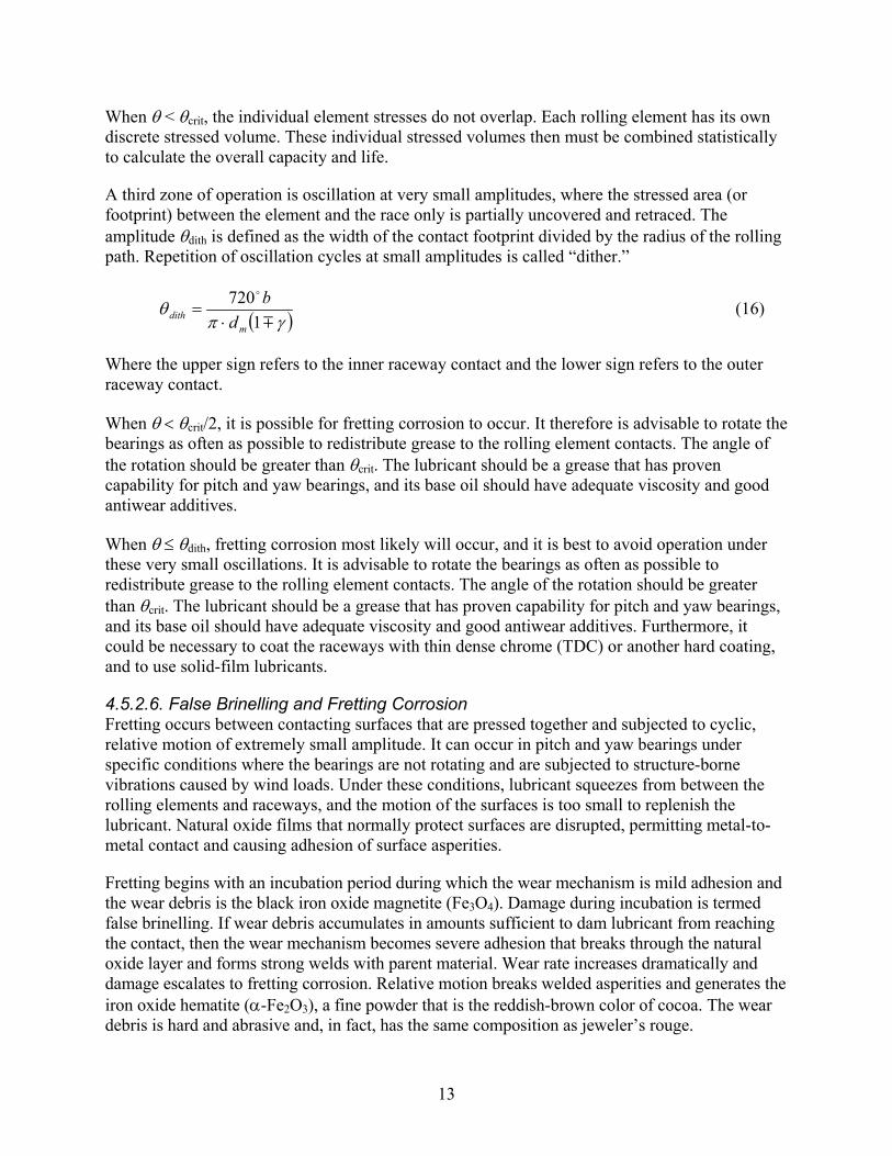
For an oscillating bearing, the critical amplitude of oscillation (θcrit) is defined as the angle of rotation of the inner raceway relative to the outer raceway, for which the raceway portion stressed by one rolling element (ball or roller) touches—but does not overlap—the raceway stressed by adjacent rollers.
( )γθ
1720
Zcrit = (15)
Where the upper sign refers to the outer raceway and the lower sign to the inner raceway.
The amplitude of oscillation is defined in Figure 4. Angle θ is one-half the total arc traced during one cycle of oscillation. Angle φ, used by Harris and Kotzalas [5], is one-quarter of the total arc traced during one cycle.
Figure 4. Amplitude angle for one cycle of oscillation
When θ > θcrit, the contact stresses of the individual rolling elements overlap. The total stressed volume for each raceway then is proportional to the product of the arc length of the amplitude of oscillation, the element contact width b, and the depth to the critical shear stress amplitude. The total stressed volume and number of stress repetitions per cycle are identical to a bearing in continuous rotation when θ = 180°.
13
When θ < θcrit, the individual element stresses do not overlap. Each rolling element has its own discrete stressed volume. These individual stressed volumes then must be combined statistically to calculate the overall capacity and life.
A third zone of operation is oscillation at very small amplitudes, where the stressed area (or footprint) between the element and the race only is partially uncovered and retraced. The amplitude θdith is defined as the width of the contact footprint divided by the radius of the rolling path. Repetition of oscillation cycles at small amplitudes is called “dither.”
( )γπθ
1720
mdith d
b⋅
= (16)
Where the upper sign refers to the inner raceway contact and the lower sign refers to the outer raceway contact.
When θ < θcrit/2, it is possible for fretting corrosion to occur. It therefore is advisable to rotate the bearings as often as possible to redistribute grease to the rolling element contacts. The angle of the rotation should be greater than θcrit. The lubricant should be a grease that has proven capability for pitch and yaw bearings, and its base oil should have adequate viscosity and good antiwear additives.
When θ ≤ θdith, fretting corrosion most likely will occur, and it is best to avoid operation under these very small oscillations. It is advisable to rotate the bearings as often as possible to redistribute grease to the rolling element contacts. The angle of the rotation should be greater than θcrit. The lubricant should be a grease that has proven capability for pitch and yaw bearings, and its base oil should have adequate viscosity and good antiwear additives. Furthermore, it could be necessary to coat the raceways with thin dense chrome (TDC) or another hard coating, and to use solid-film lubricants.
4.5.2.6. False Brinelling and Fretting Corrosion Fretting occurs between contacting surfaces that are pressed together and subjected to cyclic, relative motion of extremely small amplitude. It can occur in pitch and yaw bearings under specific conditions where the bearings are not rotating and are subjected to structure-borne vibrations caused by wind loads. Under these conditions, lubricant squeezes from between the rolling elements and raceways, and the motion of the surfaces is too small to replenish the lubricant. Natural oxide films that normally protect surfaces are disrupted, permitting metal-to-metal contact and causing adhesion of surface asperities.
Fretting begins with an incubation period during which the wear mechanism is mild adhesion and the wear debris is the black iron oxide magnetite (Fe3O4). Damage during incubation is termed false brinelling. If wear debris accumulates in amounts sufficient to dam lubricant from reaching the contact, then the wear mechanism becomes severe adhesion that breaks through the natural oxide layer and forms strong welds with parent material. Wear rate increases dramatically and damage escalates to fretting corrosion. Relative motion breaks welded asperities and generates the iron oxide hematite (α-Fe2O3), a fine powder that is the reddish-brown color of cocoa. The wear debris is hard and abrasive and, in fact, has the same composition as jeweler’s rouge.

14
Fretting damages bearings by forming ruts along lines of contact. False brinelling ruts are shallow and the damage usually is benign. Fretting corrosion forms relatively deep ruts that can cause bearing failure. During operation, bearings with severe fretting corrosion can generate a sharp hammering noise, or the bearing can jam and cease to rotate. Furthermore, fretting corrosion can cause macropitting or initiate fatigue cracks which, if in high-stress areas, can propagate to failure.
The basic dynamic axial load rating for complete rotation must be modified to accommodate bearing oscillation when θ ≥ θcrit.
p
aosca CC/1
,180
=
θ
(17)
Where exponent p equals 3 for ball bearings and p equals 4 for roller bearings.
For ball bearings when θ < θcrit, the following equation is used.
033.010/3
,180 ZCC aosca
=
θ
(18)
For roller bearings when θ < θcrit, the following equation is used.
028.09/2
,180 ZCC aosca
=
θ
. (19)
For an oscillating bearing, the speed is expressed in oscillations per minute (opm). The fatigue life of an oscillating rolling bearing is then calculated as follows.
For thrust ball bearings:
3,
10
=
ea
osca
PC
L (20)
where L10 is expressed in millions of oscillations.
For thrust roller bearings fatigue life is calculated as follows.
3/10,
10
=
ea
osca
PC
L (21)
Equation 11 is used to calculate the modified rating life. Using equation 9, the life also can be expressed in hours, where N is the constant speed of oscillation (in opm).

15
The yaw and pitch bearings in a wind turbine application generally do not operate under constant load and speed; rather, the operating conditions vary. These variable conditions can be divided into a number of discrete sets of conditions, each associated with dynamic equivalent load (Peak), speed of oscillation (Nk), oscillation amplitude (θk), and duration of operation (tk). In this case, the dynamic equivalent axial load over the duty cycle can be calculated as follows.
p
nk
k
xkkk
nk
k
xkkk
peak
ea
tN
tNPP
/1
1
1
=
∑
∑=
=
=
=
θ
θ (22)
Where:
exponent p = 3 for ball bearings and 10/3 for roller bearings;
exponent x = 9/10 for ball bearings and 8/9 for roller bearings when θ > θcrit; and
exponent x = 1 for both ball and roller bearings when θ ≤ θcrit.
4.5.3. ISO Standard Life Equation 23 gives bearing fatigue life in millions of revolutions according to ISO Standard 281 [1].
p
ea
aISOISOm P
CaaL
= 1 (23)
Where exponent p equals 3 for ball bearings and 10/3 for roller bearings. Similar to equation 11, a1 equals life modification factor for reliability; values of a1 are obtained from Table 3. However, aISO is an integrated life modification factor, a function of a fatigue limit load Pu (obtainable for each bearing from the manufacturers catalog) and the dynamic equivalent axial load Pea (see [1], [5]). As shown in Harris and Kotzalas [5], aISO can be calculated using the following formula.
432
1
2111.0
ee
ea
ue
eISO PPxxa
−−=
ηκ
(24)
In equation 24, κ is a measure of the adequacy of lubrication. It is related to Λ such that κ equals Λ1.12. As indicated in section 4.5.2.3, in a yaw or pitch bearing application Λ << 0.5; and Λ equals 0.1 is a satisfactory assumption.
Therefore, κ can be assumed to be 0.076 for a yaw or pitch bearing. Table 6 provides values of constants x1 and x2, and exponents e1 – e4 for thrust ball and roller bearings with marginal lubrication.

16
Table 6. Constants and Exponents for Thrust Bearings (Using Equation 24)
Bearing Type x1 x2 e1 e2 e3 e4 Thrust ball 2.5671 2.2649 0.054381 0.83 1/3 -9.3 Thrust roller 1.5859 1.3993 0.054381 1.00 0.4 -9.185
In equation 24, η defines the level of particulate contamination in the grease lubricant in the bearing. As determined from ISO Standard 281 [1] and Harris and Kotzalas [5], the following equation can be used to calculate η for a grease-lubricated yaw or pitch bearing.
−= 3/1
255.068.01 1173.0
mm d
cdc κη η < 1 (25)
The constants c1 and c2 are defined in terms of the level of particulate contamination in the bearing grease lubricant; they are given in Table 7.
Table 7. Constants c1 and c2 Versus Contamination Level
Contamination Level c1 c2 High cleanliness 0.0864 0.6796 Normal cleanliness 0.0432 1.141 Slight-to-typical contamination (dm < 500 mm) 0.0177 1.887 Slight-to-typical contamination (dm ≥ 500 mm) 0.0177 1.677 Severe contamination 0.0115 2.662 Very severe contamination 0.00617 4.06
ISO Standard 281 [1] applies specifically to bearings fabricated from good-quality CVD 52100 steel, through-hardened to a minimum of 58 HRC. As indicated in Section 2, yaw and pitch bearings are generally fabricated using surface-hardened steel rings. Therefore, the results of a life evaluation using ISO Standard 281 do not strictly apply; they might tend to be optimistic with regard to fatigue endurance. The surface-hardened rings tend to have a hardness less than 58 HRC, however, therefore the basic dynamic axial load rating Ca must be reduced using equation 12. Hence, for a yaw or pitch bearing, equation 23 becomes the following.
( ) p
ea
aISOISOm P
HRCCaaL
=
6.3
158 (26)
Considering the load and speed variation over a duty cycle, equation 22 can be used to determine the dynamic equivalent axial load (Pea).
4.5.4. Stress-Life Method The stress-life method for estimating bearing fatigue life makes use of the following formula.
p
ea
aSLSLm P
CaaL
= 1 (27)

17
In equation 27, similar to equation 11, a1 is the life modification factor for reliability (values of a1 are obtained from Table 3). As noted in section 3 (above), aSL is a factor that integrates—in the form of a subsurface and surface distribution of Von Mises stresses—all identified conditions that influence rolling contact fatigue. These conditions include the following.
• Hertz stresses
• Contact surface shear stresses due to sliding friction
• Residual stresses due to heat treatment and material processing
• Ring hoop stresses due to press fitting and rotation
• Lubricant contamination
Harris and Kotzalas [5] and Barnsby et al. [7] describe the stress-life method and calculation of the individual fatigue-influencing stresses in significant detail. To calculate aSL for the bearing application, it is necessary to calculate aSLmj for each rolling element–raceway contact and determine the life for each contact. For a yaw or pitch bearing, however, the dynamic equivalent axial load (Pea) is assumed to apply equally to each contact. Therefore, the equivalent load on each contact (Qmj = Pea /Zsinα; aSLmj) can be determined for this value of Qmj and the Hertz stresses and friction due to bearing internal speeds and lubrication associated with Qmj.
Furthermore, the stress-life method is applicable to bearings fabricated from component materials other than CVD 52100 steel. These materials are identified by a Von Mises fatigue limit stress (ΦVM,lim). Table 8, taken from Harris and Kotzalas [5], provides values of ΦVM,lim for various steels that might be used to fabricate yaw and pitch bearing components. It is noted that, when carburizing or induction-hardened steels are used, a compressive residual stress also must be included in the determination of aSL. A value of –170 MPa can be considered.
Table 8. Mises Fatigue Limit Stress (ΦVM,lim ) for Various Steels
Steel ΦVM,lim (MPa)
CVD 52100, minimum 58 HRC 684 SAE 4320/8620 case-hardening, minimum 58 HRC 590 VIMVAR M50, minimum 58 HRC 717 VIMVAR M50NiL, minimum 58 HRC 579 Induction-Hardened 450
For every contact, a distribution of at least 100 values of ΦVM both on and below the contact surface is included in the calculation of aSL. A computer program is required to calculate aSL. A program called ASMELife can be purchased from ASME International [7]. This program contains all the required lubrication and contamination data necessary to perform calculations. In the absence of specified input on component surface roughness and bearing internal dimensions, the program estimates the data.
If the bearing steel is not hardened to 58 HRC minimum, then equation 28 can be used to calculate life.

18
( ) p
ea
aSLSLm P
HRCCaaL
=
6.3
158 (28)
The considerations for calculating the life of oscillating application bearings, as explained above, also pertain to the calculations of the stress-life method.
5. Bearing Static Capacity
5.1. Permanent Deformation A static load is a load acting on a nonrotating (non-oscillating) bearing. Permanent deformations appear in elements and raceways under a static load of moderate magnitude and increase gradually with increasing load. Experience shows that a total permanent deformation of 0.0001 of the rolling element diameter, at the center of the most heavily loaded element–raceway contact, can be tolerated in most bearing applications without impairment of the subsequent bearing operation. The basic static load rating of a rolling bearing is based on this consideration.
Tests indicate that a ball or roller load of the magnitude that yields a permanent deformation of magnitude 0.0001D corresponds to the calculated maximum Hertz stress shown in Table 9.
Table 9. Maximum Hertz Stress (Permanent Deformation = 0.0001D)
Bearing Type
Maximum Hertz Stress (MPa)
Ball 4,200 Roller 4,000
5.2. Maximum Ball or Roller Load For a yaw or pitch bearing, the maximum ball or roller load (Qmax) can be calculated as a function of the applied radial, thrust, and moment loading, as follows.
++=
ααα sin4
sincos2
max ZdM
ZF
ZFQ
m
ar (29)
5.3. Maximum Contact Stress The maximum stress acting normal to the rolling element–raceway contact—Hertz stress—is the compressive stress at the center of the contact. The average Hertz contact stress is the element load divided by the contact area. For a ball bearing, the contact is an ellipse having semi-major axis a and semi-minor axis b; the area of the ellipse is πab. The maximum Hertz stress is given by the following equation.
abQS
πmax
max5.1
= (30)
For a cylindrical roller-raceway, the contact approximates a rectangle of length le and half-width b; the contact area is 2ble. The maximum compressive contact stress is determined as follows.

19
eblQ
Sπ
maxmax
2= (31)
5.4. Contact Dimensions 5.4.1. Point Contact The condition in which no load has been applied and two surfaces contact each other at a single point is defined as “point contact.” When load is applied between the surfaces, flattening occurs near the contact point (shown in Figure 5); the area of the contact is elliptical in form. In Figure 6, considering a ball bearing, “Body a” represents the ball, and “Body b” represents either the inner or outer bearing raceway.
Figure 5. Schematic of two solid elastic curved bodies (Body a, Body b) compressed by load Q
Each body is represented by the principal radii of curvature in orthogonal planes 1 and 2 (i.e., ra1, ra2, rb1, and rb2). Curvature is defined as the reciprocal of radius (i.e., curvature ρ = 1/r). Radius always is positive, but curvature can be positive or negative. If the center of curvature lies within the solid body, curvature is positive; if it lies outside of the solid body, curvature is negative. Hence, for a ball, curvature is positive; for a raceway groove, curvature is negative.
With regard to the bodies in contact, two parameters (which are functions of contact body curvatures) are required to define the dimensions of the contact. These are Σρ, curvature sum:
221 bbIaa ρρρρρ +++=∑ (32)

20
and curvature difference F(ρ):
( )∑
−+−=
ρρρρρ
ρ 2121 bbaaF (33)
for a ball bearing,
∑
±−=
γγρ1
214DDfD m
m m = inner, outer (34)
and
( )
±−
±
=
γγ
γγ
ρ
1214
121
m
mm
f
fF m = inner, outer. (35)
In equations 34 and 35, the upper signs refer to the inner raceway contact and the lower signs refer to the outer contact. For ball bearing contacts, the contact ellipse dimensions are given by the following.
3/1*0236.0
Σ
=ρ
Qaa (36)
3/1*0236.0
Σ
=ρ
Qbb (37)
In equations 36 and 37, a* and b* are functions of F(ρ); they can be obtained by interpolation in Table 10 (from Harris and Kotzalas [5] for steel bodies). The principal radii for a four-point contact ball bearing are described in Figure 6. The equations for the radii of curvature for a four-point contact ball bearing are given in Table 11.
5.4.2. Line Contact The condition in which no load has been applied and two surfaces just contact each other on a single line is called “line contact.” When load is applied between the surfaces flattening occurs near the contact line, and the area of the contact is rectangular in form.
The contact semi-width (b) of the rectangle of contact can be calculated directly as a function of the summation of curvature (Σρ). The equation for the contact semi-width b is given below. The curvatures for a cylindrical cross-roller bearing are provided in Table 12.
2/1
00335.0
=
∑ ρelQb (38)

21
Table 10. Values a* and b* Versus F(ρ)
F(ρ) a* b* 0.0 1.0 1.0 0.1075 1.0760 0.9318 0.3204 1.2623 0.8114 0.4795 1.4556 0.7278 0.5916 1.6440 0.6687 0.6716 1.8258 0.6245 0.7332 2.011 0.5881 0.7948 2.265 0.5480 0.83495 2.494 0.5186 0.87366 2.800 0.4863 0.90999 3.233 0.4499 0.93657 3.738 0.4166 0.95738 4.395 0.3830 0.97290 5.267 0.3490 0.983797 6.448 0.3150 0.990902 8.062 0.2814 0.995112 10.222 0.2497 0.997300 12.789 0.2232 0.9981847 14.839 0.2072 0.9989156 17.974 0.18822 0.9994785 23.55 0.16442 0.9998527 37.38 0.13050 1.0 ∞ 0.0
Figure 6. Radii of curvature for a four-point contact ball bearing
rb2 inner
rb2 outer
α
rb1 inner
dm/2
D ra1
rb1 outer

22
Table 11. Curvatures for a Four-Point Contact Ball Bearing
Curvature Inner Raceway Outer Raceway ρa1
D2
D2
ρa2
D2
D2
ρb1
−γ
γ12
D
+−
γγ1
2
D
ρb2
Dfi
1−
Dfo
1−
Table 12. Curvatures for a Cylindrical Cross Roller Bearing
Curvature Inner Raceway Outer Raceway ρa
D2
D2
ρb
−γ
γ12
D
+−
γγ1
2
D
Σρ ρa + ρb ρa + ρb 5.5. Static Load Factor The static load factor (SF) is the ratio of the allowable ball or roller load to the actual ball or roller load. The static load factor should be greater than 1 to assure some margin of safety with regard to the static capacity. The SF is linear because it is based on load; SF equals 1.5 means that the ball or roller load could be increased by a factor of 1.5 before it equals the static capacity or maximum allowable non-Brinell load.
The static capacity is expressed in terms of the maximum Hertz contact stress Smax (equation 30, equation 31). The SF can be calculated from the maximum Hertz contact stress for four-point contact ball bearings as follows.
3
max
4200
=
SSF (39)
The SF can be calculated for cylindrical cross roller bearings as follows.
2
max
4000
=
SSF (40)

23
It sometimes is necessary for the ball or roller load to be calculated when the maximum Hertz contact stress (Smax.) is known. This usually is the case when applying the SF to the load. For four-point contact ball bearings the following applies.
( )( )2
3
max2 1
5.1**0236.0
∑
=
ρ
π SbaQ (41)
For cylindrical cross roller bearings the following applies.
( )∑
⋅⋅=
ρπ
400335.0 2
maxSlQ e (42)
5.6. Effect of Surface Hardness on Static Capacity Static capacity is based on a component hardness of 58 HRC minimum. The static capacity decreases as hardness is reduced. For ball bearings, Harris and Kotzalas [5] provide this hardness reduction factor (fs) in terms of Vickers hardness (HV), as follows.
2
8005.1
=
HVf s fs, ≤ 1 (43)
For roller bearings the following applies.
2
8002
=
HVf s fs, ≤ 1. (44)
Decreases in static capacity for reduced hardness also are shown in Table 13 as a function of the HRC surface hardness.
Table 13. Hardness Reduction Factor fs Versus Hardness
HRC HV Ball
Bearing Roller
Bearing 58 660 1 1 56 620 0.901 1 55 600 0.844 1 50 500 0.586 0.781
6. Estimation of the Case-Core Interface Depth
6.1. Design Stresses Yaw and pitch bearings (as illustrated in Figure 1) are case-hardened. This heat-treatment process is intended to produce a raceway hardness of 58 HRC. Through the “case,” the hardness decreases gradually to HRC 50, and then decreases rapidly to the core hardness of the ring material. The depth below the surface to HRC 50 hardness is called the effective case depth (he). The application of a concentrated (Hertz contact) ball or roller load results in significant subsurface shear stresses which reach down into the core material (illustrated in Figure 7).

24
Figure 7. Typical subsurface shear stress curve (Note that the data are in inches and psi; to convert inches to millimeters (mm), multiply by 25.4;
to convert psi to MPa, divide by 145.)
The core deteriorates if the subsurface shear stress at the depth where the core hardness starts exceeds the yield stress in shear or the limit shear stress in fatigue of the core material. Such deterioration eliminates support for the hardened case material. Two types of failure then can occur. The core can be crushed by physically pressing the hardened case material into the core, or the lack of support for the core can cause the case to crack and disintegrate. The depth at which the core hardness starts can be estimated as 110% of the effective case depth (he) (see Figure 7).
The shear stress considered is the maximum shear stress (τ45) which acts on a 45-degree plane and is one-half the difference between the maximum and minimum principal stresses acting at the point. The normal stresses acting at the center of a ball or roller contact are principal stresses. In determining the ability of the component to withstand the applied loading, Sague and Rumbarger [11] employ the maximum shear stress (τ45) and the allowable yield and fatigue stresses in shear. Zwirlein et al. [12] use the triaxial combined stress and the tensile yield stress as the allowable stress. The latter is the Distortion Energy Hypothesis (DEH) approach. The maximum shear stress approach is used here.
6.2. Allowable Shear Stresses for Yield and Fatigue The allowable yield shear and the allowable fatigue shear stresses are given in Table 14 and shown in Figure 8. These allowable stress values cover a range of core hardness from 20–40 HRC (226–370 HB). It is noted that the yield stress in shear equals 0.425 times the ultimate strength in tension, and the fatigue strength in shear equals 0.6 times the yield stress in shear.

25
Table 14. Allowable Subsurface Shear Stresses
Rockwell C Hardness (HRC)
Brinell Hardness (HB)
Yield Strength in Shear (MPa)
Fatigue Strength in Shear (MPa)
40 371 530.3 318.2 35 327 454.5 272.7 30 286 398.6 239.2 25 253 351.7 211.0 20 226 304.8 182.9
Figure 8. Allowable subsurface shear stresses (Note that the data are in ksi; to convert ksi to MPa, divide by 0.145.)
6.3. Calculation of Subsurface Shear Stress The subsurface shear stress can be calculated using the parameter ζ, a function of the ratio b/a of the contact surface and the dimensionless depth z/b below the surface. This relationship is illustrated in Figure 9 and further defined in Table 15. The desired value of ζ is found by interpolation for the desired depth, z/b, where z is the depth to the start of the core hardness or 110% of the case depth, as shown in Figure 7. Using either Figure 9 or Table 15 to determine ζ, the subsurface shear stress τ at depth z/b is then given by the following equation.
5108754.1 −⋅
⋅= ∑ρζ
τb
(45)

26
Figure 9. Subsurface shear stress parameter versus z/b and b/a (Curve A: b/a = 0; B: b/a = 0.1; C: b/a = 0.2; D: b/a = 0.3; E: b/a = 0.4; F: b/a = 0.5)
Table 15. Subsurface Shear Stress Parameter Versus z/b and b/a
z/b b/a =0 b/a =0.1 b/a =0.2 0.0 0.000 0.022 0.040 0.2 0.161 0.180 0.190 0.4 0.251 0.268 0.273 0.6 0.291 0.305 0.306 0.8 0.300 0.313 0.311 1.0 0.293 0.304 0.299 1.5 0.252 0.260 0.250 2.0 0.211 0.217 0.203 2.5 0.179 0.183 0.166 3.0 0.154 0.156 0.137 4.0 0.119 0.118 0.097 5.0 0.097 0.092 0.071 6.0 0.082 0.075 0.054 8.0 0.062 0.051 0.034 10.0 0.050 0.037 0.023 15.0 0.033 0.020 0.011 20.0 0.025 0.012 0.006
In Figure 9 and Table 15, b/a equals 0 represents the line contact.
6.4. Evaluation of the Case-Core Interface In addition to achieving satisfactory fatigue endurance and sufficient static capacity, case-core interface design criteria must be satisfied. Failure to satisfy these criteria affects the bearing fatigue life and static capacity.

27
The yield shear stress associated with the greatest rolling element–raceway contact load (Qmax) under the ultimate or worst-case loading condition should be less than the allowable yield shear stress at the depth where core hardness starts (i.e., 110% of the case depth). Failure to satisfy this condition requires a reduction in the static load factor (see Section 5). The allowable Hertz contact stress for the static capacity (see Section 5) must be reduced to a value that has a subsurface shear stress equal to the subsurface shear stress at the core boundary.
The subsurface shear stress associated with load Qmax for the dynamic equivalent axial load should be equal to or less than the fatigue shear stress. A reduction in the L10 fatigue life is indicated if the subsurface shear stress exceeds the allowable fatigue shear stress at the core boundary. Considering equation 11, an additional life modification factor (a5) is required to accommodate this condition, such that the following is true.
1,
,5 ≤=
actualshear
allowableshearaτ
τ (46)
7. Effective Lubrication
A meaningful oil film thickness cannot be generated in a slowly and intermittently moving (oscillating) grease-lubricated yaw or pitch bearing. Therefore a clean grease with good boundary lubrication additives (especially for oscillating conditions) should be selected on the basis of experience for use in wind turbine yaw and pitch bearings. A seal system (integral or external) also is essential for achieving satisfactory operation.
A fretting-corrosion type of raceway and rolling element surface failure commonly is encountered in yaw and pitch bearings. The fretting corrosion appears as elliptical or rectangular footprints at ball or roller spacing in the bearing. The markings are tiny corrosion pits caused by the lubricant being forced out of the contact area (by a small load increase) and then not being able to re-enter the contact zone. The unprotected surface then is subject to corrosion pitting. Most grease rated for oscillation use can coat the rolling contact surfaces and maintain corrosion protection. In extreme cases, coating the raceways is an option. A TDC coating increases the bearing cost significantly but provides increased protection.
One manufacturer of wind turbine yaw and pitch bearings suggests using the Hertz contact stress limits given in Table 16 as means to limit fretting-corrosion types of failures.
Table 16. Hertz Stress Limits to Minimize Fretting Corrosion Failures in Yaw and Pitch Bearings
Operating Condition Maximum Suggested Hertz
Stress(MPa) Ultimate 3,200 Maximum operating 2,800 Mean operating 2,400

28
8. Bearing Friction Torque
A practical running friction torque estimate for yaw and pitch bearings is important to the equipment designer. The torque estimate suggested is conservative and results in values that can be used for drive system or actuator design. The running torque estimate provided below is for yaw and pitch bearings of the four-point contact ball bearing and cross roller bearing configurations (see Figure 1). These bearings include plastic spacers between the rolling elements and integral seals. Starting friction might exceed the running friction by a factor of as much as 1.5. The following is the equation for running torque.
++= ar
m
m FFd
MdT 2.24.4
2µ (47)
For use with equation 47, Table 17 gives values of µ, the bearing coefficient of friction.
Table 17. Bearing Friction Coefficient μ Versus Bearing Type
Bearing Type µ Ball bearing with cage 0.003 Ball bearing with spacers 0.004 Cross cylindrical roller bearing 0.004
9. Miscellaneous Design Considerations
9.1. General A number of important non-rolling items can adversely affect yaw and pitch bearing service life if they are not properly satisfied. A partial list includes:
• External bolting;
• Cages or separators; and
• Integral seals.
9.2. External Bolting The proper operation of yaw and pitch bearings requires that the external mounting bolts (Figure 2, Figure 3) have sufficient preload and strength to maintain the rings in contact with their mounting surfaces at all times. The maximum rolling element load (Qmax) is used, with proper consideration of the number of elements and the number of bolts, to determine the maximum bolt load. See References, entries14 through 18, for a brief bibliography of technical papers covering a bolted joint.
9.3. Cages or Separators Most yaw and pitch bearings are supplied with plastic spacers between each rolling element. A four-point contact ball bearing has cylindrical spacers with hemispherical indented ends. The cross roller bearing has plastic saddle-type spacers, which conform to the two adjacent rollers with axes of rotation 90 degrees apart. The ball spacers for larger balls (50-mm diameter and larger) often have a steel-plate reinforcement cast into the plastic.

29
Use of segmented cages is very rare for yaw and pitch bearings. The opening that the cage requires between the raceways significantly reduces the available load-carrying ball path. The bearing manufacturer should be consulted about spacer design. The spacer material also must be compatible with the selected lubricant.
9.4. Integral Seals Wind turbine yaw and pitch bearings are usually supplied with integral rubbing lip seals. The bearing manufacturer should be consulted about materials, design, and placement of the integral seals. The seal material must be compatible with the selected lubricant.

30
Nomenclature
Symbol Description Units a semimajor axis of contact ellipse mm a* dimensionless semimajor axis of contact ellipse mm a1 life modification factor for reliability a2 life modification factor for materials a3 life modification factor for lubrication a4 life modification factor for flexible support structure aISO integrated ISO life factor aSL integrated stress-life factor b semiminor axis of contact ellipse mm b* dimensionless semiminor axis of contact ellipse mm c1, c2 constants to calculate contamination factor Ca basic dynamic axial load rating N Ca,osc basic dynamic axial load rating for oscillation N D diameter of rolling element mm dm pitch diameter of bearing mm e eccentricity mm e1, e2, e3, e4 exponents to calculate aISO fcm bearing geometry-material factor in load rating equation fi inner raceway groove radius/D fo outer raceway groove radius/D Fa applied axial load N Fay, Fax components of Fa along the y and x axes N Fr applied radial load N fs hardness reduction factor F(ρ) curvature difference i number of rows of rolling elements he effective case depth to 50 HRC mm h0 minimum lubricant film thickness micrometers HB Brinell hardness HRC Rockwell C scale hardness HV Vickers hardness number le effective roller length mm L bearing life for rotation rev, hr LISOm ISO Standard modified rating life rev, hr Lnm ANSI/ABMA modified rating life rev, hr LSLm stress-life modified rating life rev, hr L1 0 bearing life for 90% survival (revolutions) M applied moment load kNm N bearing net rotational or oscillating speed rpm, opm Pea dynamic equivalent axial load N Pn dynamic equivalent load-for-load speed condition n N Pu fatigue limit load N Qj individual ball or roller load N

31
Qmax maximum ball or roller load N ra1, ra2 principal radii of curvature for Body a mm rb1, rb2 principal radii of curvature for Body b mm sm raceway rms surface “roughness” micrometers sRE ball or roller rms surface “roughness” micrometers SF static load factor Smax maximum Hertz contact stress on roller or ball with highest load MPa tk time fraction at operating condition k T running friction torque N-m x1, x2 constants to calculate aISO X dynamic radial load factor Y dynamic axial load factor z depth of maximum shear stress (length) mm Z number of rolling elements in a row z/b dimensionless depth parameter α contact angle ° γ Dcosα/dm ζ parameter for calculating subsurface shear stress η lubricant contamination factor θ amplitude of oscillation (one-half total arc in one cycle) ° θcrit critical amplitude of oscillation ° θdith repetition of oscillation cycles at small amplitudes ° κ lubrication effectiveness factor Λ lubrication film parameter µ coefficient of friction ρ curvature mm-1
ΦVM,lim Von Mises fatigue limit stress MPa Σρ curvature sum mm-1
τ subsurface shear stress MPa τ0 maximum orthogonal shear stress MPa τ45 maximum shear stress MPa φ angular location of individual ball or roller °

32
References
1. International Organization for Standardization, ISO Standard 281, “Rolling Bearings—Dynamic Load Ratings and Rating Life,” 2007.
2. International Organization for Standardization, ISO Standard 76, “Rolling Bearings—Static Load Ratings,” 1989.
3. American National Standards Institute, ANSI/ABMA 9-1990, “Load Ratings and Fatigue Life for Ball Bearings,” 1990.
4. American National Standards Institute, ANSI/ABMA 11-1990, “Load Ratings and Fatigue Life for Roller Bearings,” 1999.
5. Harris, T.A.; Kotzalas, M.N. Rolling Bearing Analysis. 5th edition. London: Taylor and Francis Group, CRC Press, 2007.
6. Zaretsky, E.V., ed. STLE Life Factors for Rolling Bearings. STLE SP-34. Park Ridge, IL: Society of Tribologists and Lubrication Engineers, 1992.
7. Barnsby, R.; Duchowski, J.; Harris, T.; Ioannides, S.; Loesche, T.; Nixon, H.; Webster, M. Life Ratings for Modern Rolling Bearings—A Design Guide for the Application of International Standard ISO 281/2, TRIB, Vol. 14. New York: ASME International, 2003.
8. Lundberg, G.; Palmgren, A. “Dynamic Capacity of Rolling Bearings,” Acta Polytech. Mech. Eng. Ser. 1, No. 3, 7. Stockholm: Royal Swedish Academy of Engineering Sciences, 1947.
9. Lundberg, G.; Palmgren, A. “Dynamic Capacity of Roller Bearings,” Acta Polytech. Mech. Eng;. Ser. 2, No. 4, 96, Stockholm: Royal Swedish Academy of Engineering Sciences, 1952.
10. Rumbarger, J.H.; Poplawski, J.V. “Correlating Computerized Rolling Bearing Analysis Techniques to the ISO Standards on Load Rating and Life,” Tribology Transactions; Vol. 37(4), 1994; pp. 793–801.
11. Sague, J.E.; Rumbarger, J.H. “Design Criteria to Prevent Core Crushing Failure in Larger Diameter, Case Hardened, Ball and Roller Bearings,” ASME Paper 77-DE-39, 1977.
12. Zwirlein, O.; Wieland, W.A. “Case Depth for Induction Hardened Slewing Ring Bearings,” SAE Paper No. 831371, 1983.
13. Rumbarger, J.H. “Evaluation of the Life Margin of Oscillating Needle Roller Bearings,” ASLE Trans.; Vol. 12, No. 2, 1968, pp. 162–170.
14. Gusovius, E. “Method of Designing Bolted Joints for Mounting Large-Diameter Bearings,” SAE Paper No. 790906, 1979.
15. Aaronson, S.F. “Analyzing Critical Joints,” Machine Design, January 21, 1982.
16. “Systematic Calculation of High Duty Bolted Joints with One Cylindrical Bolt,” Guideline VDI 2230; Germany: VDI Society for Product Development Guidelines, 1986.
17. Radzimovsky, E.I. “Bolt Design for Repeated Loadings,” Machine Design, November 1952.
18. Baumgartner, T.C.; Kull, F.R. “Determining Preload in a Bolted Joint,” Machine Design, February 13, 1964.

33
Appendix A. Wind Turbine Yaw Bearing
A.1. Operating Conditions and Bearing Dimensions A wind turbine yaw bearing mounted in a tubular (cylindrical) tower is required to endure for 20 years, considering 50% operating time while subjected to loading according to the duty cycle in Table A-1.
Table A-1. Yaw Bearing Load Duty Cycle
Operating Condition
Time of Operation (%)
Wind Speed (m/sec)
Radial Load (kN)
Thrust Load (kN)
Moment Load (kNm)
1 32 6.250 30.60 226.0 89.27 2 16 8.944 52.96 226.0 178.4 3 15 11.61 57.18 226.0 233.7 4 20 13.42 52.51 226.0 251.3 5 15 17.89 40.94 226.0 273.2 6 2 33.36 36.05 226.0 299.9
Limit load — 147.9 226.0 2430 The outer raceway of the bearing is stationary with respect to applied loading and rotates at 0.285 rpm. A cylindrical cross roller bearing, as illustrated in Figure A-1 and having the dimensions and material properties provided in Table A-2, has been selected for the application. The rollers are oriented at 45° contact angle, as shown in Figure A-1. The lower surface of the bearing inner ring is mounted to the tubular tower. The inner raceway is stationary. Alternate rollers carry the thrust load in a given direction. Hence, half the rollers are oriented to carry the applied thrust load.
Figure A-1. Yaw bearing coordinates and loads

34
Table A-2. Yaw Bearing Dimensions and Material Properties
Parameter Dimensions Pitch diameter, dm 1454 mm* Roller diameter, D 44.45 mm* Roller effective length, le 38.10 mm* Number of rollers per row, Z 40 Contact angle, α ° Raceway hardness 56 HRC minimum Core hardness 250 HB minimum Case depth 4.572 mm
*Bearing length dimensions were converted from inches to millimeters. A.2. Dynamic Equivalent Loads Dynamic equivalent loads for each operating condition of Table A-1 are calculated according to equation 6.
marea d
MFFP 275.0 ++=
Also, the eccentricity of applied thrust load Fa can be calculated from the following.
am FdMe 2
= (A-1)
Using equation 6 and equation A-1, the dynamic equivalent axial Pea for each operating condition of Table A-1 can be calculated. These loads are given in Table A-3.
Table A-3. Yaw Bearing Dynamic Equivalent Axial Loading for the Duty Cycle
Operating Condition
Time of Operation (%)
Dynamic Equivalent Axial Load, Pea (N)
Eccentricity of Thrust Loading, e
1 32 371,700 0.543 2 16 511,100 1.085 3 15 590,300 1.422 4 20 611,100 1.529 5 15 632,500 1.662 6 2 665,600 1.825
Limit load — 3,679,000 14.79 Using equation 8 and equation 10 show that the dynamic equivalent axial load over the duty cycle is as follows.
10/36
1
3/10
= ∑
=
=
k
kkeakea tPP (A-2)

35
( ) ( ) ( ) ( ) 20.0111.615.0903.516.0111.532.0717.3[ 3/103/103/103/10 ⋅+⋅+⋅+⋅=eaP
( ) ( ) N553.03/103/10 10437.510]02.0656.615.0325.6 ⋅=⋅⋅+⋅+
Hence, the overall operating condition for evaluating rolling contact fatigue life is as follows.
Pea = 543,700 N at 0.285 rpm.
A.3. Basic Dynamic Axial Load Rating Using equation 3 yields the following.
( ) αα tancos 27/294/39/7 DZlfC ecma =
For the following bearing
02162.01454
45cos45.44cos===
mdD αγ
from the interpolation in Table 2 for γ = 0.02162, fcm = 130.8. Therefore, the following results.
( ) ( ) ( ) NCa627/294/39/7 10587.145tan45.444045cos10.388.130 ⋅==
A.4. Basic L10 Life The basic rating life for the bearing is determined using equation 8.
revPCL
ea
a 63.10
5
63.10
10 1054.3510437.510587.1
⋅=
⋅⋅
=
=
The L10 fatigue life is converted to hours of operation using equation 9.
hrNmrLhrL 6
6610
10 10078.260285.0
1054.3560
10)()( ⋅=⋅⋅
=⋅
⋅=
A.5. Modified L10 Life According to ANSI/ABMA Standard 11 The modified rating life is calculated using equation 11. For L10 life calculation, the life modification factor for reliability from Table 3 remains a1 equals 1. The steel is 56 HRC, which is not as hard as the minimum requirement of 58 HRC standard, a life reduction factor a2 equals 0.66 can be determined from Table 4.
As indicated in Section 4.5.2.3, as a result of the very slow speed of assumed rotation, the bearing will operate with boundary lubrication only, and a life modification factor for lubrication a3 not greater than 0.1 can be considered. Owing to the flexible support structure for the bearing associated with the tubular tower mounting, a life modification factor a4 equals 0.85 from Table 5 can be employed.

36
The following considers all of these effects.
hrLaaaaL knm56
10321 10166.110078.285.01.066.01.... ⋅=⋅⋅⋅⋅⋅==
The required fatigue life for the yaw bearing application is 50% operation over 20 years or 87,600 hours. Here, L10m equals 116,600 hours, and bearing life appears satisfactory. It might be more appropriate to consider L1m in lieu of L10m. Table 3 shows that for 99% reliability, a1 is equal to 0.25. This yields: L1m = 28,000 hr. This life appears marginally satisfactory.
A.6. Modified L10 Life According to ISO Standard 281 ISO Standard LISOm is calculated using equation 23. In equation 23, the integrated life modification factor aISO is determined using equation 24 and equation 25. Moreover, for the slow rotation, grease-lubricated bearing, as stated in Section 4.5.3, a lubrication effectiveness factor κ equals 0.076 can be assumed. Additionally, from Table 6 the contamination constants, c1 equaling 0.0432 and c2 equaling 1.141 for a grease lubricant of normal cleanliness can be assumed. Hence, from equation 25 the following can be determined.
From equation 24, using Table 6 to determine constants and exponents for a thrust roller bearing.
432
1
2111.0
ee
ea
ue
eISO PPxxa
−−=
ηκ
To calculate aISO, it also is necessary to calculate the fatigue limit load Pu. As indicated in Section 4.5.3, Pu. is found in bearing manufacturers’ catalogs for most bearings. In this example, however, Pu must be calculated. ISO Standard 281 [1] gives the following formula to approximate Pu for thrust roller bearings.
3.00 1002.8
=
DC
P au (A-3)
Where C0a is the basic static axial capacity of the bearing. In turn, C0a can be calculated according the method of ISO Standard 76 [2] as follows.
( ) αγ sin12200 DZlC ea −= (A-4)
( ) ( )( )
06394.01454
141.111454076.00432.0173.01173.0 3/155.068.0
3/1255.068.0
1 =
−⋅⋅=
−=
mm d
cdc κη
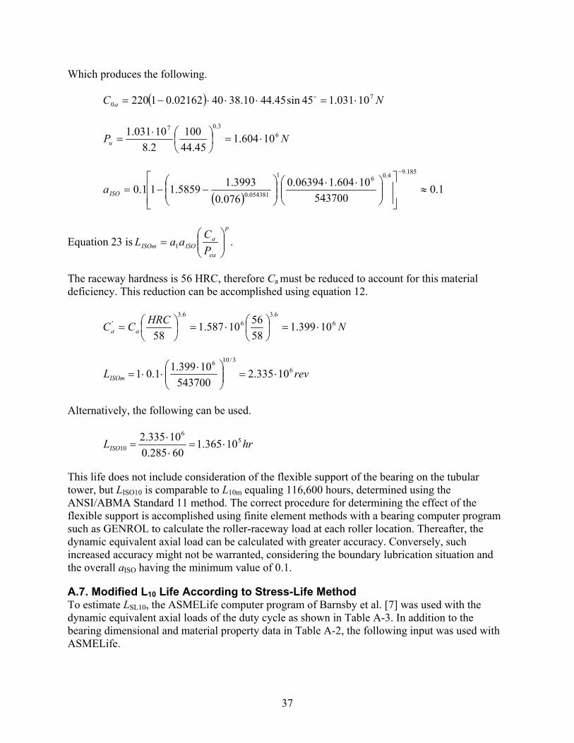
37
Which produces the following.
( ) NC a7
0 10031.145sin45.4410.384002162.01220 ⋅=⋅⋅⋅−=
NPu6
3.07
10604.145.44
1002.810031.1
⋅=
⋅
=
( )1.0
54370010604.106394.0
076.03993.15859.111.0
185.94.061
054381.0 ≈
⋅⋅
−−=
−
ISOa
Equation 23 isp
ea
aISOISOm P
CaaL
= 1 .
The raceway hardness is 56 HRC, therefore Ca must be reduced to account for this material deficiency. This reduction can be accomplished using equation 12.
NHRCCC aa6
6.36
6.3' 10399.1
585610587.1
58⋅=
⋅=
=
revLISOm6
3/106
10335.2543700
10399.11.01 ⋅=
⋅⋅⋅=
Alternatively, the following can be used.
hrLISO5
6
10 10365.160285.0
10335.2⋅=
⋅⋅
=
This life does not include consideration of the flexible support of the bearing on the tubular tower, but LISO10 is comparable to L10m equaling 116,600 hours, determined using the ANSI/ABMA Standard 11 method. The correct procedure for determining the effect of the flexible support is accomplished using finite element methods with a bearing computer program such as GENROL to calculate the roller-raceway load at each roller location. Thereafter, the dynamic equivalent axial load can be calculated with greater accuracy. Conversely, such increased accuracy might not be warranted, considering the boundary lubrication situation and the overall aISO having the minimum value of 0.1.
A.7. Modified L10 Life According to Stress-Life Method To estimate LSL10, the ASMELife computer program of Barnsby et al. [7] was used with the dynamic equivalent axial loads of the duty cycle as shown in Table A-3. In addition to the bearing dimensional and material property data in Table A-2, the following input was used with ASMELife.

38
• Grease with ISO VG460 mineral oil for a slow-rotation bearing
• Normal cleanliness of the grease with regard to particulate contamination
• Operating temperature assumed to be 50ºC
• Bearing rings manufactured of SAE 8620 steel having compressive residual stress in the case of –170 MPa
• Bearing basic dynamic axial load rating reduced to 1.587 x 10⁶ N to account for 56 HRC hardness of raceways
• Surface roughness of raceways and rollers of 0.4 microns
Using the inputs noted above, ASMELife estimated overall: LSL10 = 130,700 hr. A minimum lubricant effective parameter of κ equaling 0.055 also was calculated, however, and the following cautionary statement was output.
Lambda < 0.5 indicates LUBRICATION EFFECTIVENESS IS EXTREMELY MARGINAL even if the lubrication supply to the roller-raceway contacts appears sufficient. The asperities of the roller and raceway surfaces are in substantial contact; fatigue endurance can be substantially less than predicted.
Thus, all of the modified life prediction methods indicate satisfactory L10 life in the same approximate range; however, higher reliability life (e.g., L1) might be marginal.
A.8. Maximum Roller Load The yaw bearing static capacity is based on the maximum Hertz contact stress at the center of the most heavily loaded roller, Qmax. According to ISO Standard 76 [2], the maximum Hertz contact stress should not exceed 4,000 MPa for a roller bearing. Also, according to Table 13, there is no reduction in the basic static capacity for the roller-raceway owing to the 56 HRC minimum raceway hardness. From Table 13, fs equals 1.0.
Maximum roller load, Qmax, is calculated using equation 29 for the dynamic equivalent load and the limit load situations.
++=
ααα sin4
sincos2
max ZdM
ZF
ZFQ
m
ar
Table A-4. Qmax for Equivalent and Limit Loads
Load Fr
(kN) Fa
(kN) M
(kNm) Qmax (N)
Dynamic equivalent 46.93 226.0 217.0 32,414 Limit 147.90 226.0 243.0 254,800
A.9. Contact Semi-Width, Hertz Stress, and SF The semi-width (b) of the contact area rectangle is determined using equation 38. In turn, equation 38 requires the calculation of curvature sum Σρ. From Table 12, for the inner raceway contact the following is the case.

39
( ) ( )104599.0
02162.0145.442
12
122 −=
−=
−=
−−=∑ mm
DD
D γγ
γρ
mml
Qbe
e 4556.004599.01.38
3241400335.000335.02/12/1
=
⋅=
=
∑ ρ
mmb 277.104599.01.38
25480000335.02/1
lim =
⋅=
Hertz contact stress is calculated using equation 31, and static load factor SF is calculated using equation 40; for example:
eblQ
Sπ
maxmax
2= and
2
max
4000
=
σSF .
The results are given in Table A-5.
Table A-5. Qmax for Equivalent and Limit Loads
Load b
(mm) Smax
(MPa) SF
(NΑmm) Dynamic equivalent 0.4556 1189 11.32
Limit 1.277 3334 1.439
Static load factor equal to 1.439 shows that the yaw bearing has a satisfactory static capacity under the limit load conditions.
A.10. Case-Core Interface From Table A-2 the case depth is determined to be 4.572 mm. As stated in Section 5.7.3, the core zone (i.e., HRC = 50) commences at 110% of the case depth or 5.029 mm. From Table A-5 for the limit load application, contact area semi-width equals 1.277 mm, such that dimensionless depth z/b equals 5.029/1.277 which equals 3.938. For the rectangular contact area b/a equals 0.
Therefore, from Table 15 by interpolation at b/a equaling 0, subsurface shear stress parameter ζ equals 0.121. The shear stress at this depth is then determined using equation 45.
MPab
9.378108754.1
04599.0277.1121.0108754.1 55 =
⋅⋅⋅
=⋅
⋅= −−
∑ρζτ
For the bearing, a minimum core hardness of 250 HB has been specified. From Table 14 at this condition, the yield strength in shear is 346.5 MPa, and the fatigue strength in shear is 207.9 MPa. Note that for the core, τ equals 378.9 MPa; this is greater than the 346.5 MPa allowable. Therefore core crushing or cracking of the core material under the limit load is

40
possible. Either higher core hardness or a greater case depth needs to be specified to achieve an allowable shear yield stress that is greater than 378.9 MPa.
For the applied dynamic equivalent axial load, calculated subsurface shear stress τ is determined using equation 45, however, from Table A-5, b equals 0.4556 mm and ζ equals 0.049. In this case, τ = 54.8 MPa. Because 54.8 MPa is less than the fatigue strength in shear of 207.9 MPa, the case-core interface is satisfactory from a fatigue standpoint.
A.11. Evaluation for Potential Fretting Corrosion According to Table 16, the calculated maximum operating Hertz stress does not exceed the suggested limit to avoid a fretting-corrosion type of failure. Maximum Hertz stress under the limit load condition is marginally greater than the recommended limit for fretting corrosion avoidance. These results are summarized in Table A-6.
Table A-6. Comparison of Calculated Hertz Stresses with Recommended Limit Stresses to Avoid Fretting in Bearing Raceways
Load Hertz Stress
(MPa) Recommended Hertz Stress Limit to Avoid Fretting (MPa)
Dynamic equivalent 1189 2800 (maximum operating) Limit 3334 3200 (ultimate)
A.12. Lubricant and Lubrication A lubricant selection has not been included with this pitch bearing rating example. The grease selected should be recommended for oscillating motion conditions, and also should have excellent antiwear and extreme pressure additive characteristics. Frequent (daily) movement of the yaw bearing through a large angle (90 degrees) is recommended to redistribute grease to the rollers and roller path surfaces.
A.13. Bearing Friction Torque The estimated rolling friction torque is calculated using equation 47 using a value of friction coefficient µ equaling 0.004. Therefore the following is the case.
++= ar
mm FF
dMdT 2.24.4002.0
Table A-7 provides calculated values of bearing friction torque for the average bearing load condition and the limit load condition.
Table A-7. Bearing Friction Torque for Average and Limit Loads
Load Fr
(kN) Fa
(kN) M
(kNm) T
(kNm) Average 44.21 226.0 1.894 2.607
Limit 147.9 226.0 2430 23.26 Starting friction torque or a change in friction torque with a reversal of yaw bearing motion could be 1.5 times the running torque. Estimated running torque values are given in Table A-7.

41
The estimated running friction torque is conservatively high for sizing drives and actuators. The actual running friction torque might be less than the estimated maxima. The torque estimates include integral seal drags and spacer drag.
A.14. Design Summary The yaw bearing design in Figure A-1 and Table A-2, operating under the loads and constant speed duty in Table A-1, has been evaluated in accordance with NREL Guideline DG03. The yaw bearing does not satisfy the criterion to avoid core crushing. Either the core hardness or the case depth must be increased. A minimum case depth of 5.08 mm with a 250 HB minimum core hardness (for example) would satisfy the case-core design criteria.
The yaw bearing design meets or exceeds all of the following design criteria.
• L10 fatigue life in rotation
• Static capacity
• Satisfactory lubrication
• Non-rolling items
Based on increased reliability (e.g., L1), fatigue endurance could be marginal.

42
Appendix B. Wind Turbine Pitch Bearing
B.1. Operating Conditions and Bearing Dimensions A wind turbine pitch bearing is required to function for 20 years, considering 50% operating time and loading according to the duty cycle of Table B-1.
Table B-1. Bearing Duty Cycle Speeds and Loads
Operating Condition
Wind Speed (m/sec)
Operating Time (%)
Speed (opm*) Nk
Oscillation Amplitude (°)
Radial Load (kN)
Axial Load (kN)
Moment Load (kNm)
1 31 37.75 13.5 0.552 13.4 32.5 217.1 2 45 15.96 19.9 0.792 25.0 64.7 366.1 3 58 13.51 26.2 1.264 26.1 84.0 372.2 4 67 17.67 27.7 1.308 23.9 88.4 325.3 5 89 13.36 28.4 1.122 19.6 94.0 228.6 6 112 1.75 28.5 1.076 17.8 88.4 187.7
Limit load 46.9 145.0 937.1 *Oscillations per minute The loads were derived by the wind turbine designer from detailed load studies of rainbow cycles versus load. (NREL DG01 covers the determination of wind turbine loads.) The loads are applied to the bearing inner raceway, which oscillates relative to the outer raceway. The pitch bearing coordinate system and load application are shown in Figure B-1.
Figure B-1. Pitch bearing coordinates and loads
For this application a four-point contact ball bearing was selected, as illustrated in Figure B-2, which has the dimensions and properties given in Table B-2.

43
Figure B-2. Four-point contact ball bearing
Table B-2. Four-Point Ball Bearing Dimensions and Material Properties
Parameter Dimension/Value Pitch diameter, dm 940 mm Ball diameter, D 45 mm Contact angle, α 45° Number of balls per row, Z 52 Number of rows, i 1 Inner raceway groove radius/D, fi 0.52 Outer raceway groove radius/D, fo 0.52 Outer raceway critical amplitude of oscillation, θcrit,o 14.33° Inner raceway critical amplitude of oscillation, θcrit,i 13.39° Raceway surface hardness 58 HRC minimum Core hardness 250 HB
B.2. Bearing Dynamic Equivalent Loads and Speeds For each operating condition k (k = 1….6 and limit load) of Table B-1, a dynamic equivalent axial load can be calculated using equation 6. Table B-3 shows the calculated values Peak.
m
kakrkeak d
MFFP
275.0 ++=
Table B-3. Bearing Dynamic Equivalent Axial Loads over the Duty Cycle
Operating Condition
Operating Time Fraction (tk )
Oscillation Amplitude θk(°)
Speed (osm) Nk Peak (kN)
1 0.3775 0.552 13.5 504.5 2 0.1596 0.792 19.9 862.4 3 0.1351 1.264 26.2 895.5 4 0.1767 1.308 27.7 798.5 5 0.1336 1.122 28.4 595.1 6 0.0175 1.076 28.5 501.1
Limit load 2174 For each operating condition of the duty cycle of Table B-1, θk < θcrit. Therefore, the duty cycle loading specified in Table B-1 can be reduced to one dynamic equivalent axial load using equation 22 for exponent x equaling 1, as follows.

44
p
nk
kkkk
nk
kkkk
peak
ea
tN
tNPP
/1
1
1
=
∑
∑=
=
=
=
θ
θ
Substituting the values of Table B-3 into this equation yields the following.
The average speed of oscillation during the duty cycle is given by the following.
The equivalent oscillation amplitude can be determined as follows.
000.10175.5.28.......3775.5.13
076.10175.05.28.......552.93775.5.13
1
1 =⋅++⋅
⋅⋅++⋅⋅==
∑
∑=
=
=
=nk
kkk
nk
kkkk
e
tN
tN θθ
B.3. Bearing Basic Dynamic Axial Load Rating for Rotation For a rotating ball bearing having balls greater than 25.4 mm (1 in) in diameter, as shown in Section 4.3, the basic dynamic axial load rating Ca is given by equation 2.
( ) αα tancos647.3 4.13/27.0 DZifC cma =
The geometry-material constant fcm is determined from Table 1 as a function of contact angle α and parameter γ equaling Dcosα/dm.
03385.0940
45cos45cos===
mdD αγ
By interpolating in Table 1, fcm equals 66.74. Therefore the following is the case.
( ) ( ) ( ) kNNCa 86.54854886045tan455245cos174.66647.3 4.13/27.0==⋅⋅=
Table 1 refers to bearings having 0.53 conformity (raceway groove radius/D), and the bearing raceways have 0.52 conformity, as noted in Section 4.3, therefore Ca as determined above must be multiplied by 1.172, producing: Ca = 643.3 kN.
∑=
=
⋅+⋅+⋅+⋅+⋅+⋅==6
10175.05.281336.04.281767.07.271351.02.261596.09.193775.05.13
k
kkkave tNN
( ) ( ) kNPea 3.765076.10175.05.28.............552.03775.05.13
076.10175.05.287.506..........552.03775.05.135.5043/133
=
⋅⋅+⋅⋅⋅⋅⋅++⋅⋅⋅
=
opmNave 0.21=

45
B.4. Basic Dynamic Axial Load Rating for the Oscillating Bearing The critical amplitude of oscillation for the four-point contact ball bearing inner race is 13.39°. Each of the amplitudes of oscillation in Table B1 is less than the critical amplitude of oscillation. For this condition, the basic dynamic axial load rating calculated for the rotating bearing must be modified according to equation 18 as follows.
( ) kNZCC aosca 348052000.1
1803.643180 033.03.0
033.010/3
, =
=
=
θ
B.5. Basic L10 Life The basic rating life for the bearing is determined using equation 7, modified to employ Ca,osc.
oscP
CL
ea
osca 633
,10 1002.94
3.7653480
⋅=
=
=
The L10 fatigue life is converted to hours of operation using equation 9.
hrN
moLhrLave
7462060211002.94
6010)()(
6610
10 =⋅⋅
=⋅
⋅=
B.6. Modified L10 Life According to ANSI/ABMA Standard 11 The modified rating life is calculated using equation 11. For L10 life calculation, the life modification factor for reliability from Table 3 remains a1 equaling 1. The steel is 58 HRC minimum according to the standard requirement, therefore life modification factor for material a2 equaling 1 can be used.
As indicated in Section 4.5.2.3, considering oscillatory motion that is not conducive to the formation of lubricant films that can separate balls from raceways, the bearing will operate with boundary lubrication only, and a life modification factor for lubrication (a3) that is not greater than 0.1 can be considered.
Owing to the flexible support structure for the bearing associated with the mounting, from Table 5 a life modification factor a4 equal to 0.85 can be employed. Considering all of the following effects.
hrLaaaaL knm 63447462085.01.011.... 10321 =⋅⋅⋅⋅==
Required fatigue life for the pitch bearing application is 50% operation over 20 years or 87,600 hours. Because L10m equals 6,344 hours, bearing life does not appear satisfactory. Therefore a bearing with increased basic dynamic axial load rating could be required. To satisfy the latter requirement, a double-row bearing might be considered. This would be an eight-point contact ball bearing (illustrated in Figure B-3), having the dimensions given in Table B-4.

46
Figure B-3. Eight-point contact ball bearing
Table B-4. Eight-Point Ball Bearing Dimensions and Material Properties
Parameter Dimension/Value Pitch diameter, dm 940 mm Ball diameter, D 35 mm Contact angle, α 45° Number of balls per row, Z 65 Number of rows, i 2 Inner raceway groove radius/D, fi 0.52 Outer raceway groove radius/D, fo 0.52 Outer raceway critical amplitude of oscillation, θcrit,o 11.38° Inner raceway critical amplitude of oscillation, θcrit,i 10.79° Raceway surface hardness 58 HRC minimum Core hardness 250 HB
For each operating condition of the duty cycle of Table B-1, as for the four-point contact ball bearing, θk < θcrit. Therefore the duty cycle dynamic equivalent load remains the same (i.e., 765.3 kN). The basic dynamic axial load rating, however, is increased as a result of the greater number of bearing rows. The internal geometry also is altered as a result of the reduced ball diameter. Therefore the following is the case.
02633.0940
45cos35cos===
mdD αγ
By interpolating in Table 1, fcm equals 61.91. Therefore the following is the case.
( ) ( ) ( ) kNNCa 1.67567510045tan356545cos291.61647.3 4.13/27.0==⋅⋅⋅=
Table 1 refers to bearings having 0.53 conformity (raceway groove radius/D), and the bearing raceways have 0.52 conformity, as stated in Section 4.3, therefore Ca as determined above must be multiplied by 1.172, giving: Ca = 791.2 kN.
The critical amplitude of oscillation for the eight-point contact ball bearing inner raceway is 10.79Ε. Each of the amplitudes of oscillation in Table B-1 is less than the critical amplitude of

47
oscillation. For this condition the basic dynamic axial load rating calculated for the rotating bearing must be modified according to equation 18.
( ) kNZCC aosca 431265000.1
1802.791180 033.03.0
033.010/3
, =
=
=
θ
The basic rating life for the bearing is determined using equation 7, modified to employ Ca,osc.
oscP
CL
ea
osca 633
,10 109.178
3.7654312
⋅=
=
=
The L10 fatigue life is converted to hours of operation using equation 9.
hrN
moLhrLave
980,1416021109.178
6010)()(
6610
10 =⋅⋅
=⋅
⋅=
hrLaaaaL knm 070,12980,14185.01.011.... 10321 =⋅⋅⋅⋅==
As stated above, required fatigue life for the pitch bearing application is 50% operation over 20 years or 87,600 hours. Because L10m equals 12,070 hours, the life for this bearing is not satisfactory. Therefore, a bearing with higher load capacity is required. Table 3 shows that, for 99% reliability, a1 equals 0.25. This yields: L1m = 24,270 hr. This life seems marginal.
B.7. Modified L10 Life According to ISO Standard 281 ISO Standard LISOm is calculated using equation 23. In equation 23, the integrated life modification factor aISO is determined using equation 24 and equation 25. Moreover, for the relatively slow oscillation, grease-lubricated bearing, as stated in Section 4.5.3, a lubrication effectiveness factor κ equaling 0.076 can be assumed. Additionally, from Table 7 the contamination constants c1 equaling 0.0432 and c2 equaling 1.141 for a grease lubricant of normal cleanliness can be assumed. Hence, from equation 25 the following is determined.
( ) ( )( )
04942.0940
141.11940076.00432.0173.01173.03/1
55.068.03/1
255.068.01 =
−⋅⋅=
−=
mm d
cdc κη
From equation 24, using Table 6 to determine constants and exponents for a thrust roller bearing produces the following.
432
1
2111.0
ee
ea
ue
eISO PPxxa
−−=
ηκ
To calculate aISO, it also is necessary to calculate the fatigue limit load Pu. As indicated in Section 4.5.3, Pu. is found in bearing manufacturers’ catalogs for most bearings. In this example,

48
however, Pu must be calculated. ISO Standard 281 [1] gives the following formula to approximate Pu for thrust ball bearings.
5.00 100
22
=
DCP a
u (B-1)
Where C0a is the basic static axial capacity of the bearing. In turn, C0a can be calculated according the method of ISO Standard 76 [2] as follows.
αsin20 ZDfC sa = (B-2)
Where the fo is a function of γ, determined from ISO Standard 76 [2] to be 59.39 for a thrust ball bearing. In equation B-2, Z is the number of balls carrying load in one direction; for the eight-point ball bearing, Z equals 130. Therefore the following is the case.
( ) NZDC sa622
0 10688.645sin3513039.59sin ⋅=⋅⋅== αϕ
NPu5
5.06
10138.535
10022
10688.6⋅=
⋅
=
( )1.0
76530010138.504942.0
076.02649.25671.211.0
3.93/1583.0
054381.0 ≈
⋅⋅
−−=
−
ISOa
Because aISO equals 0.1, LISOm essentially is the same as L10m, according to ANSI/ABMA Standard 9 [3] (i.e., 12,070 hours). A life reduction for load distribution among the bearing balls can be considered due to the flexibility of the bearing-mounting structure.
B.8. Modified L10 Life According to Stress-Life Method Due to the inability of the oscillating bearing to form lubricant films of sufficient thickness to separate the balls from the raceways during bearing operation, and the resulting surface asperity-asperity contact experienced during boundary lubrication, aSL also will not be greater than 0.1. Therefore, LSLm is essentially the same as L10m according to ANSI/ABMA Standard 9 [3], (12,070 hours).
B.9. Maximum Ball Load The pitch bearing static capacity is based on the maximum Hertz contact stress at the center of the most heavily loaded ball, Qmax. According to Table 9, maximum Hertz stress should not exceed 4,200 MPa. Qmax is calculated using equation 29. The maximum ball load for the two-row, eight-point contact ball bearing is 55%—and not 50% of the maximum ball load for a single-row ball thrust bearing. A 55%/45% thrust load sharing of the two rows is considered the best possible load distribution ratio because of tolerances and variation of internal dimensions between the bearing rows. (The insufficient L10 life of the four-point contact ball bearing means that there is no need to consider that bearing further in this analysis.)

49
Maximum roller load (Qmax) is calculated using a modified equation 29 for the dynamic equivalent load and the limit load situations, as follows.
++=
ααα sin4
sincos2
55.0max ZdM
ZF
ZF
Qm
ar
Table B-5 provides the peak dynamic, dynamic equivalent and limit loads, and the calculated value of Qmax for each load condition.
Table B-5. Qmax for Equivalent and Limit Loads
Load Fr
(kN) Fa
(kN) M
(kNm) Qmax (kN)
Maximum dynamic load (3) 26.1 84.0 372.2 20.58 Dynamic equivalent 22.7 82.1 314.6 17.55 Limit 46.9 145.0 937.1 50.58
Note that, for the dynamic equivalent load, each component was calculated individually (e.g., Fre, Fae, Me). This is not completely accurate, however the result is more conservative than using a simple mean load component.
B.10. Contact Ellipse Dimensions The maximum ball load for the limit load case and the maximum ball load under fatigue loading can be used to determine the contact ellipse dimensions and maximum Hertz stress for the eight-point contact ball bearing. For the ball bearing, contact stresses are greater at the inner raceway than the outer raceway, therefore only inner raceway stresses are estimated here. To determine the contact ellipse dimensions, Σρ and F(ρ) first are determined. Equation 34 produces the following.
∑
−
+−=γ
γρ
1214DDfD i
i
106089.002633.01
02633.0352
3552.01
354 −=
−+
⋅−=∑ mmiρ
From equation 35 the following is determined.
( ) 9278.0
02633.0102633.02
52.014
02633.0102633.02
52.01
1214
121
=
−⋅
+−
−⋅
+=
−
+−
−
+
=
γγ
γγ
ρ
i
ii
f
fF
The dimensionless quantities a* and b* are functions F(ρ). The values for a* and b* are calculated by interpolation from the dimensionless parameters of Table 10. Therefore a*i equals 3.571 and b*i equals 0.4276. For the limit load condition, dimensions ai and bi are calculated using equation 36 and equation 37.

50
mmQaai
ii 922.706089.0
50580571.30236.00236.03/13/1
* =
⋅⋅=
Σ
=ρ
mmQbbi
ii 9486.006089.0
505804276.00236.00236.03/13/1
* =
⋅⋅=
Σ
=ρ
B.11. Hertz Contact Stress and Static Load Factor For the limit load condition, the maximum Hertz stress (Smax) is calculated using equation 30.
MPaba
QSii
32149486.0922.7
505805.15.1 maxmax =
⋅⋅⋅
=⋅
=ππ
The static load factor is calculated using equation 40.
232.2321442004200 33
max
=
=
=
SSF
The eight-point contact ball bearing design exceeds the requirement that the static factor (SF) under limit load meets or exceeds 1.5; hence, the design is satisfactory from a maximum static load standpoint.
B.12. Case–Core Interface The case depth was not specified for the eight-point contact ball bearing; therefore, it is necessary to define an adequate value for that parameter based on the case avoiding crushing during application of the limit load. In Table B-2, bearing ring core hardness was specified at 250 HB. From Table 14, the allowable shear stress with regard to core crushing for this hardness is 346.5 MPa. According to equation 45, the following is the case.
MPab
5.346108754.1 5 =
⋅
⋅= −
∑ρζτ
Here, Σρi equals 0.06089 and bi equals 0.9482, therefore the parameter ζi equals 0.1125. The dimensional depth at which ζi equals 0.1125 occurs can be determined from Table 15 via a double interpolation. The first interpolation is based on the inverse ellipticity ratio for the contact area. For the inner raceway-ball contact curvatures of the eight-point contact ball bearing, the following is the case.
1197.0571.3
4276.0*
*
===i
i
i
i
ab
ab
Hence, for ζi equaling 0.1155 and bi /ai equaling 0.1197, z/b equals 4.054. Therefore, the case depth is: 4.054 x 0.9482 mm = 3.844mm. The core depth is 110% of the case depth, thus core depth is 4.228 mm.

51
It next is necessary to check the adequacy of this case depth with regard to fatigue subsurface shear stress. From Table 14, the allowable fatigue shear stress is 207.9 MPa. Considering the peak dynamic load condition of Table B-1, as shown in Table B-5, Qmax equals 20.58 kN. From equation 37 the following can be determined.
mmQbbi
ii 7029.006089.0
205804276.00236.00236.03/13/1
* =
⋅⋅=
Σ
=ρ
Core depth is 4.228 mm, therefore the non-dimensional core depth is as follows.
mmbz 017.6
7026.0228.4
==
Interpolating in Table 15 for bi /ai equaling 0.1197 yields: . = 0.07067. Using equation 45 produces the following.
MPab
2.161108754.1
06089.07029.007067.0108754.1 55 =
⋅⋅⋅
=⋅
⋅= −−
∑ρςτ
This fatigue shear stress is less than the 207.9 MPa allowable, giving a safety factor of 1.290 for the eight-point contact ball bearing.
B.13. Hertz Stress Limits for Avoidance of Fretting Corrosion Table 16 indicates maximum Hertz stress limits as a means to limit or prevent fretting corrosion type of failure at the ball-groove contacts. (As noted in Section 6, these limits are suggested by a manufacturer of large bearings and have not been verified or accepted as standards.) Equation 30 is used to calculate maximum Hertz stress for a ball bearing as follows.
iibaQ
Sπ
maxmax
5.1=
Values of Qmax are given in Table B-4. Contact ellipse dimensions ai and bi are calculated using equation 36 and equation 37 for the peak dynamic and limit load conditions. These values and ensuing maximum Hertz stresses are given in Table B-6, where they also are compared against the suggested Hertz stress limits.
Table B-6. Comparison of Calculated Hertz Stresses with Recommended Limit Stresses to Avoid Fretting in Bearing Raceways
Condition ai
(mm) bi
(mm) Qmax (kN)
Smax (MPa) Slimit Slimit / Smax
Peak operating load 5.870 0.7029 20.58 2,383 2,800* 1.175 Limit load 7.919 0.9482 50.58 3,216 3,200** 0.995
* Suggested maximum operating Hertz stress from Table 16. ** Suggested ultimate Hertz stress from Table 16.

52
B.14. Dither Angle The dither angle (θdith) is the zone of operation, at very small amplitude of oscillation, where the elliptical contact area between ball and raceway only is partially uncovered and retraced. The amplitude is defined as the width of the contact divided by the raceway radius. Equation 16 is used to calculate θdith for the ball-inner raceway contact of the eight-point contact ball bearing under the limit load condition.
( ) ( )
2374.002633.01940
9482.07201
720=
−⋅⋅⋅
=−⋅
=πγπ
θm
idith d
b
B.15. Lubrication A lubricant selection has not been included in this pitch bearing example. The grease selected should be recommended for oscillating conditions, and also should have excellent antiwear and extreme pressure additives. Frequent (daily) movement of the blade through a large angle (three times the critical angle θcrit or more) is recommended to redistribute grease to the ball groove surfaces. This minimum rotation (3θcrit) is calculated using equation 15 as follows.
( )
13.34)02633.01(65
72031
72033 =−⋅⋅
=−
⋅=γ
θZcrit
B.16. Friction Torque Bearing friction torque is estimated using equation 47 as follows.
++= ar
m
m FFd
MdT 2.24.4
2µ
The friction coefficient : is provided by Table 17 for the different types of pitch ball bearings (i.e., depending on mechanical means used to separate the balls).
Starting friction torque or a change in friction torque with a reversal of blade motion can be 1.5 times the running torque. Estimated running torque values for a bearing having a cage and a bearing having ball separators are given in Table B-7. The estimated running friction torque is conservative and high for the purpose of sizing drives and actuators. The friction torque estimates include the effect of drag caused by integral seals.
Table B-7. Bearing Friction Torque for Operating and Limit Loads
Operating Condition
Radial Load (kN)
Axial Load (kN)
Moment (kNm)
Trunning Cage ( µ = 0.003 kNm)
Trunning Spacers (µ = 0.004 kNm)
1 13.4 32.5 217.1 1.52 2.03 2 25.0 64.7 366.1 2.59 3.45 3 26.1 84.0 372.2 2.66 3.54 4 23.9 88.4 325.3 2.35 3.13 5 19.6 94.0 228.6 1.70 2.27 6 17.8 88.4 187.7 1.42 1.89
Limit load 46.9 145.0 937.1 6.53 8.71
53
B.17. Miscellaneous This numerical example does not include an evaluation of the mounting bolts. Other items such as cages, plastic separators, and integral rubbing seals are not subject to numerical analysis. These non-rolling items should be covered in the purchase specifications.
B.18. Summary Four-point and eight-point contact ball bearings for a pitch bearing application were evaluated with regard to design adequacy in supporting the duty cycle conditions of Table B-1. The four-point contact ball bearing was found to be inadequate to meet the fatigue endurance requirement of 20-year life considering 50% operational time. The eight-point contact ball bearing met the life requirement and further analysis was conducted for that bearing design.
Further, it was found that the eight-point contact ball bearing design meets or exceeds all of the necessary remaining design criteria:
• Static capacity;
• Adequate case depth and core hardness;
• Satisfactory lubrication; and
• Non-rolling items.
The eight-point contact ball bearing design is more costly to manufacture than the four-point contact ball bearing design. Causes for the greater cost of the eight-point contact ball bearing are (1) the second row of balls, (2) a second cage or separators, and (3) the need to assemble and disassemble the bearing during final fit-up. The intent is to match the ball diameters, raceway groove radii, and diametral clearance or preload of the two ball rows.

F1147-E(10/2008)
REPORT DOCUMENTATION PAGE Form Approved OMB No. 0704-0188
The public reporting burden for this collection of information is estimated to average 1 hour per response, including the time for reviewing instructions, searching existing data sources, gathering and maintaining the data needed, and completing and reviewing the collection of information. Send comments regarding this burden estimate or any other aspect of this collection of information, including suggestions for reducing the burden, to Department of Defense, Executive Services and Communications Directorate (0704-0188). Respondents should be aware that notwithstanding any other provision of law, no person shall be subject to any penalty for failing to comply with a collection of information if it does not display a currently valid OMB control number. PLEASE DO NOT RETURN YOUR FORM TO THE ABOVE ORGANIZATION. 1. REPORT DATE (DD-MM-YYYY)
December 2009 2. REPORT TYPE
Subcontract Report 3. DATES COVERED (From - To)
July 2008 4. TITLE AND SUBTITLE
Wind Turbine Design Guideline DG03: Yaw and Pitch Rolling Bearing Life
5a. CONTRACT NUMBER DE-AC36-08-GO28308
5b. GRANT NUMBER
5c. PROGRAM ELEMENT NUMBER
6. AUTHOR(S) T. Harris, J.H. Rumbarger, and C.P. Butterfield
5d. PROJECT NUMBER NREL/TP-500-42362
5e. TASK NUMBER WE101131
5f. WORK UNIT NUMBER
7. PERFORMING ORGANIZATION NAME(S) AND ADDRESS(ES) National Renewable Energy Laboratory 1617 Cole Blvd. Golden, CO 80401-3393
8. PERFORMING ORGANIZATION REPORT NUMBER NREL/TP-500-42362
9. SPONSORING/MONITORING AGENCY NAME(S) AND ADDRESS(ES)
10. SPONSOR/MONITOR'S ACRONYM(S) NREL
11. SPONSORING/MONITORING AGENCY REPORT NUMBER
12. DISTRIBUTION AVAILABILITY STATEMENT National Technical Information Service U.S. Department of Commerce 5285 Port Royal Road Springfield, VA 22161
13. SUPPLEMENTARY NOTES
14. ABSTRACT (Maximum 200 Words) This report describes the design criteria, calculation methods, and applicable standards recommended for use in performance and life analyses of ball and roller (rolling) bearings for yaw and pitch motion support in wind turbine applications. The formulae presented here for rolling bearing analytical methods and bearing-life ratings are consistent with methods in current use by wind turbine designers and rolling-bearing manufacturers.
15. SUBJECT TERMS yaw and pitch; motion support; wind turbine; rolling bearing analytical methods; bearing life ratings
16. SECURITY CLASSIFICATION OF: 17. LIMITATION OF ABSTRACT
UL
18. NUMBER OF PAGES
19a. NAME OF RESPONSIBLE PERSON a. REPORT
Unclassified b. ABSTRACT Unclassified
c. THIS PAGE Unclassified 19b. TELEPHONE NUMBER (Include area code)
Standard Form 298 (Rev. 8/98) Prescribed by ANSI Std. Z39.18