wind tunnel test for three co-stayed steel stack flues ... · pdf filehere, cicind 3) defines...
TRANSCRIPT
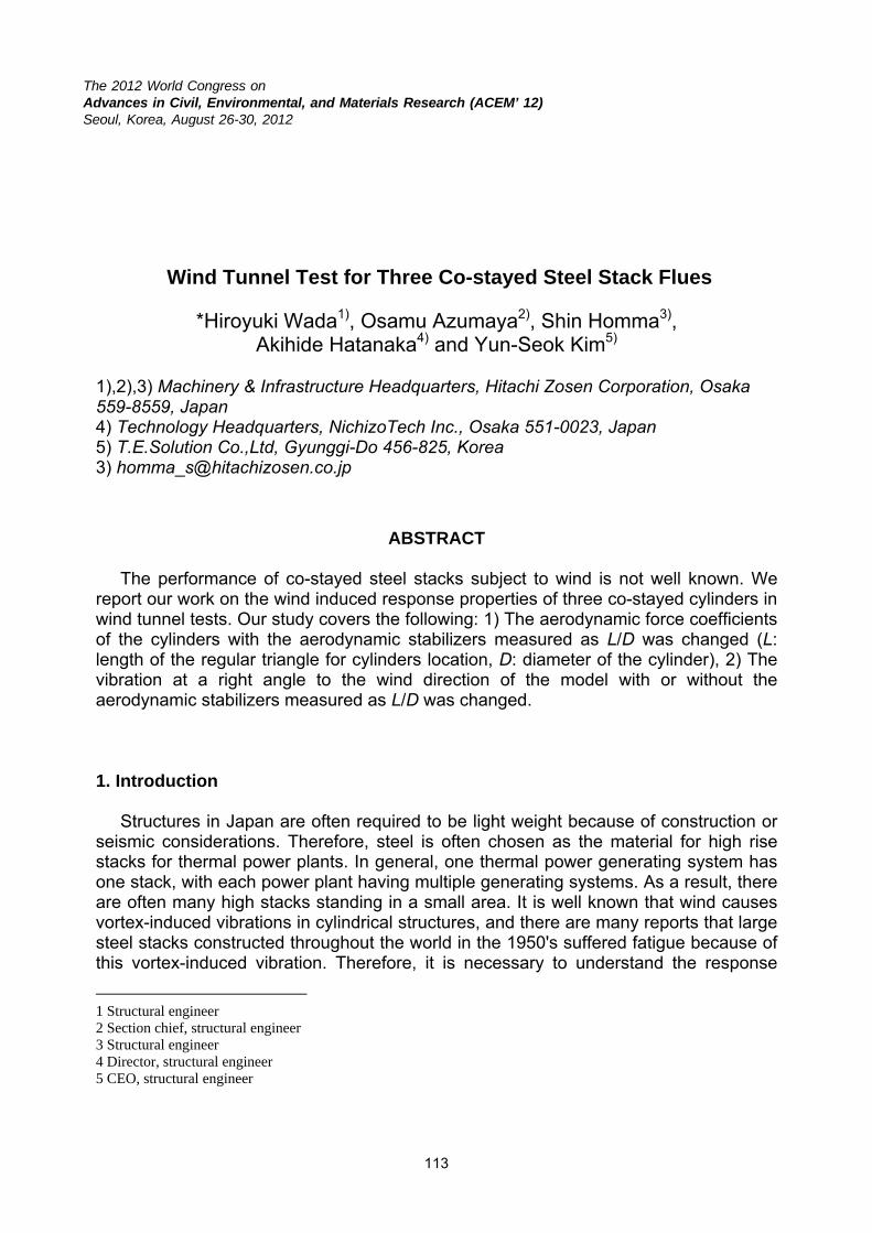
The 2012 World Congress on Advances in Civil, Environmental, and Materials Research (ACEM’ 12)Seoul, Korea, August 26-30, 2012
Wind Tunnel Test for Three Co-stayed Steel Stack Flues
*Hiroyuki Wada1), Osamu Azumaya2), Shin Homma3), Akihide Hatanaka4) and Yun-Seok Kim5)
1),2),3) Machinery & Infrastructure Headquarters, Hitachi Zosen Corporation, Osaka 559-8559, Japan 4) Technology Headquarters, NichizoTech Inc., Osaka 551-0023, Japan 5) T.E.Solution Co.,Ltd, Gyunggi-Do 456-825, Korea 3) [email protected]
ABSTRACT The performance of co-stayed steel stacks subject to wind is not well known. We report our work on the wind induced response properties of three co-stayed cylinders in wind tunnel tests. Our study covers the following: 1) The aerodynamic force coefficients of the cylinders with the aerodynamic stabilizers measured as L/D was changed (L: length of the regular triangle for cylinders location, D: diameter of the cylinder), 2) The vibration at a right angle to the wind direction of the model with or without the aerodynamic stabilizers measured as L/D was changed. 1. Introduction Structures in Japan are often required to be light weight because of construction or seismic considerations. Therefore, steel is often chosen as the material for high rise stacks for thermal power plants. In general, one thermal power generating system has one stack, with each power plant having multiple generating systems. As a result, there are often many high stacks standing in a small area. It is well known that wind causes vortex-induced vibrations in cylindrical structures, and there are many reports that large steel stacks constructed throughout the world in the 1950's suffered fatigue because of this vortex-induced vibration. Therefore, it is necessary to understand the response
1 Structural engineer 2 Section chief, structural engineer 3 Structural engineer 4 Director, structural engineer 5 CEO, structural engineer

characteristics of a steel stack to the wind. Some of these stacks can be connected and help to stay one other. But the performance of these co-stayed stacks subject to wind is not well known. We previously reported the static and dynamic wind characteristics of three co-stayed cylinders with L/D=2.0 (L: length of the regular triangle for cylinders location, D: diameter of the cylinder, ASEM+11) based on wind tunnel tests1). In this study, we report the results for cases where L/D=2.5 and 3.0. 2. Experimental 2-1. Prototype stack The layout of the prototype stack is shown in Fig. 1 and the specifications are in Table 1. The layout is a 3D rigid structure of three flues with co-stays by the beams. Each flue is 6.1-metre in diameter. They are located on a regular triangle. The tops of the flues are brought together to promote draft of the exhaust gas, but are not connected. The stack complex is sited near the sea. The exponent, α, of the power law for the vertical distribution of the wind load due to the wind speed as defined in The Building Standard Law in Japan (BSLJ 2)) can be approximated with exponent 0.1.
2-2. Methods To clarify fundamental characteristics of the wind induced response of the co-stayed cylinders, wind tunnel tests were carried out. The performance data for the wind tunnel is shown in Table 2. The scale of the stack models was 1/76.25 (flue: φ 80 mm), which was the same as the former test (ASEM+11). Figure 2 shows the wind tunnel. Using
Table 1 Specification of the prototype stack (from ASEM’11+)
Figure 1 3D Wind tunnel model of the prototype stack
(from ASEM’11+)
Type Three co-stayed steel flue stacks (concentrated nozzle)
Structure 3D rigid frame with three-column and two-layer
Flue diameter D = φ6.1m (O.D)
Height H = 80m Distance L = 12.5m (former test), 15m,18m Location seashore
Design wind speed
32m/s (mean speed of 10min at GL+10m with 50years recurrence interval)
Insulation 80mm mortar type lining inside flue Code Building Standard Law in Japan
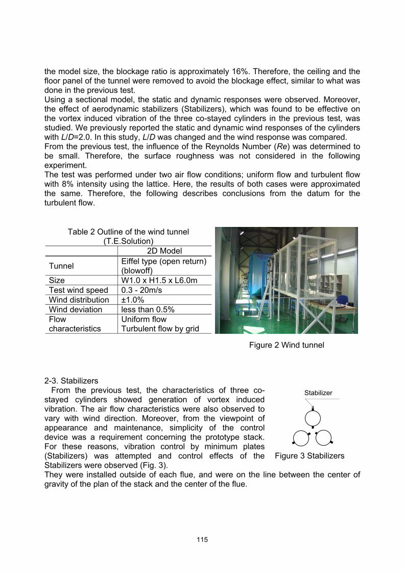
the model size, the blockage ratio is approximately 16%. Therefore, the ceiling and the floor panel of the tunnel were removed to avoid the blockage effect, similar to what was done in the previous test. Using a sectional model, the static and dynamic responses were observed. Moreover, the effect of aerodynamic stabilizers (Stabilizers), which was found to be effective on the vortex induced vibration of the three co-stayed cylinders in the previous test, was studied. We previously reported the static and dynamic wind responses of the cylinders with L/D=2.0. In this study, L/D was changed and the wind response was compared. From the previous test, the influence of the Reynolds Number (Re) was determined to be small. Therefore, the surface roughness was not considered in the following experiment. The test was performed under two air flow conditions; uniform flow and turbulent flow with 8% intensity using the lattice. Here, the results of both cases were approximated the same. Therefore, the following describes conclusions from the datum for the turbulent flow.
2-3. Stabilizers From the previous test, the characteristics of three co-stayed cylinders showed generation of vortex induced vibration. The air flow characteristics were also observed to vary with wind direction. Moreover, from the viewpoint of appearance and maintenance, simplicity of the control device was a requirement concerning the prototype stack. For these reasons, vibration control by minimum plates (Stabilizers) was attempted and control effects of the Stabilizers were observed (Fig. 3). They were installed outside of each flue, and were on the line between the center of gravity of the plan of the stack and the center of the flue.
Table 2 Outline of the wind tunnel (T.E.Solution)
Figure 2 Wind tunnel
2D Model
Tunnel Eiffel type (open return)(blowoff)
Size W1.0 x H1.5 x L6.0m Test wind speed 0.3 - 20m/s Wind distribution ±1.0% Wind deviation less than 0.5% Flow characteristics
Uniform flow Turbulent flow by grid
Stabilizer
Figure 3 Stabilizers
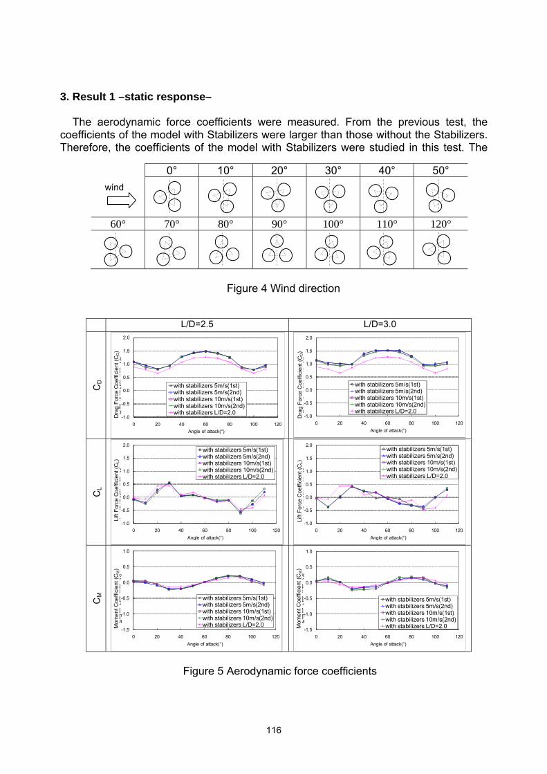
3. Result 1 –static response– The aerodynamic force coefficients were measured. From the previous test, the coefficients of the model with Stabilizers were larger than those without the Stabilizers. Therefore, the coefficients of the model with Stabilizers were studied in this test. The
L/D=2.5 L/D=3.0
CD
-1.0
-0.5
0.0
0.5
1.0
1.5
2.0
0 20 40 60 80 100 120
Drag Force Coefficient (CD)
Angle of attack(°)
with stabilizers 5m/s(1st)with stabilizers 5m/s(2nd)with stabilizers 10m/s(1st)with stabilizers 10m/s(2nd)with stabilizers L/D=2.0 -1.0
-0.5
0.0
0.5
1.0
1.5
2.0
0 20 40 60 80 100 120
Drag Force Coefficient (CD)
Angle of attack(°)
with stabilizers 5m/s(1st)with stabilizers 5m/s(2nd)with stabilizers 10m/s(1st)with stabilizers 10m/s(2nd)with stabilizers L/D=2.0
CL
-1.0
-0.5
0.0
0.5
1.0
1.5
2.0
0 20 40 60 80 100 120
Lift Force Coefficient (CL)
Angle of attack(°)
with stabilizers 5m/s(1st)with stabilizers 5m/s(2nd)with stabilizers 10m/s(1st)with stabilizers 10m/s(2nd)with stabilizers L/D=2.0
-1.0
-0.5
0.0
0.5
1.0
1.5
2.0
0 20 40 60 80 100 120
Lift Force Coefficient (CL)
Angle of attack(°)
with stabilizers 5m/s(1st)with stabilizers 5m/s(2nd)with stabilizers 10m/s(1st)with stabilizers 10m/s(2nd)with stabilizers L/D=2.0
CM
-1.5
-1.0
-0.5
0.0
0.5
1.0
0 20 40 60 80 100 120
Moment Coefficient (Cm)
Angle of attack(°)
with stabilizers 5m/s(1st)with stabilizers 5m/s(2nd)with stabilizers 10m/s(1st)with stabilizers 10m/s(2nd)with stabilizers L/D=2.0
-1.5
-1.0
-0.5
0.0
0.5
1.0
0 20 40 60 80 100 120
Moment Coefficient (CM)
Angle of attack(°)
with stabilizers 5m/s(1st)with stabilizers 5m/s(2nd)with stabilizers 10m/s(1st)with stabilizers 10m/s(2nd)with stabilizers L/D=2.0
Figure 5 Aerodynamic force coefficients
0° 10° 20° 30° 40° 50°
60° 70° 80° 90° 100° 110° 120°
Figure 4 Wind direction
wind
Dra
g Fo
rce
Coe
ffici
ent (
CD)
Dra
g Fo
rce
Coe
ffici
ent (
CD)
Lift
Forc
e C
oeffi
cien
t (C
L)
Lift
Forc
e C
oeffi
cien
t (C
L)
Mom
ent C
oeffi
cien
t (C
M)
Mom
ent C
oeffi
cien
t (C
M)

static wind force was measured at 10 degrees pitch within a 120 degree range from the structural symmetry (see Fig. 4). Non-dimensional drag coefficient (CD), lift coefficient (CL) and moment coefficient (CM) are defined as follows;
LDρU/F
Cr
DD 221
= , LDUρ
FC
r
LL 22/1
= , LDUρ
FC
r
MM 222/1
= (1)
Where FD, FL and FM: drag, lift and momentum wind force, ρ: air density, U: test wind speed, Dr: characteristic width of the model, and L: model length. Here, the width of the model is defined as three times the diameter of the model (0.8 x 3=2.4 m). The coefficients CD, CL and CM are shown in Fig. 5. The figure indicates that the lift force is fluctuating widely depending on the attack angle of the wind to the stack. From the test, the lift and momentum coefficient without Stabilizers was nearly the same for L/D=2.0, 2.5 and 3.0. However, the drag coefficient for L/D=2.5 and 3.0 was larger than for L/D=2.0. Here, CICIND3) defines the drag coefficients of the cylinders with helical strakes as 1.4, and the drag coefficients of the three co-stayed cylinders with Stabilizers for L/D=2.0 as 1.4, from the previous test. However, the maximum drag coefficient of the three co-stayed cylinders with Stabilizers for L/D=2.5 is larger than these values. 4. Result 2 –dynamic response– 4-1. cylinders without Stabilizers The degree of freedom of the wind direction was restricted, and the vibration at a right angle to the wind direction was measured. Table 3, Fig. 6 and Fig. 7 give the outline of the test.
Table 3 Outline of the 2D model test
Prototype
(analytical, from previous test)2D model
Target Actual
Size Similar model to the static wind load test
Frequency 0.89Hz (analytical) -
L/D=2.0 6.48Hz (from previous test)L/D=2.5 6.36Hz L/D=3.0 6.33Hz
Structural damping
0.5% (assumption) 0.5%
L/D=2.00.5% L/D=2.5
L/D=3.0
Equivalent mass
15.823t/m (analytical) 27.2 g/cm
L/D=2.027.0g/cm L/D=2.5
L/D=3.0Correspondingwith Re - - Without roughness
Turbulent intensity 12% (2/3 of the stack height) -
・ Uniform flow ・ the turbulent flow with 8% intensity by the grid

Figure 6 Spring support system (side view)
Flow Vibration
Oil
L/D=2.5 L/D=3.0
Axis
1 Ax
is2
Axis
3
Figure 7 Layout of the model

The damping of the model was provided by viscous oil, and the damping ratio was adjusted to 0.47%, similar to the previous test. From eigenvalue analysis of the space frame model, three structural axes were defined, which were axis-1 (Y direction), axis-2 (X direction) and axis-3 (-Y direction). Figure 8 shows the structural axes of the model. Figure 9 shows the vibration amplitude at a right angle to the wind direction. The horizontal axis of the graph indicates reduced wind speed with length D. The peak responses are observed around U/fd = 5 from all figures, which is the vortex induced vibration generated by Carman vortices from a single cylinder with the same section. Here, U/fD is the reduced wind speed (U: wind speed in the tunnel, f: natural frequency, D: diameter of the cylinder) Concerning axis-2 of “without Stabilizers,” the figure indicates that the vortex induced vibration is generated in two wind speed ranges. Kobayashi5) reports that the characteristics of a pair of cylinders located along the flow changes from the biased gap cylinders (biased) to the separated cylinders (single) according to the separation. He also reports Strouhal Number (St) for the pair of cylinders changes from 0.15 (biased) to 0.2 (single) in accordance with L/D changing from 2.0 (biased) to 5.0 (single). In the case for axis-2, the parallel cylinders along the flow exist in the layout. The reduced wind speed (U/fD) is calculated as 6.7 when L/D=2.0 and St=0.15, which coincides with the peak response of the high speed range in the figure. From the results, the L/D=2.0 model possess both parallel and single cylinder characteristics. Concerning axis-3 of “without Stabilizers,” the figure indicates a large amplitude of vortex induced vibration around U/fD=10-13 at the L/D=2.0. Choi4) reports that St=0.44 at the leeward cylinders and St=0.1 at the windward cylinder were observed for three cylinders located along axis-3 with L/D=2.0. The reciprocal of St is reduced wind speed; therefore reduced wind speed becomes 10 when St is 0.1, which coincides with the resonance wind speed range in the figure. From these results, the vortex induced vibration of the whole stack seems to be generated by the vortices from the windward cylinders.
X-axis
Y-axis
wind
Axis1 Axis2 Axis3
Primary (Y-axis)
Secondary(X-axis)
Figure 8 Eigenvalue mode of the frame model

4-2. cylinders with Stabilizers From Fig 9, the resonance amplitudes of the L/D=2.0 model with Stabilizers are smaller than those without Stabilizers for every axes. However, the amplitudes of the L/D=2.5 or 3.0 models with Stabilizers are not reduced compared to those without Stabilizers. Concerning axis-2 of “with Stabilizers,” the figure indicates that resonance exists for two wind speed ranges. From this, the models seem to have the characteristics of both the biased cylinders and single cylinder.
Without Stabilizers With Stabilizers
Axis
1
0.00
0.05
0.10
0.15
0 2 4 6 8 10 12 14 16 18
RMS response Yrms/D
Reduced Wind Speed U/fD
without stabilizers (L/D=2.0)without stabilizers (L/D=2.5)without stabilizers (L/D=3.0)
0.00
0.05
0.10
0.15
0 2 4 6 8 10 12 14 16 18
RMS response Yrms/D
Reduced Wind Speed U/fD
with stabilizers (L/D=2.0)with stabilizers (L/D=2.5)with stabilizess (L/D=3.0)
Axis
2
0.00
0.05
0.10
0.15
0 2 4 6 8 10 12 14 16 18
RMS response Yrms/D
Reduced Wind Speed U/fD
without stabilizers (L/D=2.0)without stabilizers (L/D=2.5)without stabilizers (L/D=3.0)
0.00
0.05
0.10
0.15
0 2 4 6 8 10 12 14 16 18
RMS response Yrms/D
Reduced Wind Speed U/fD
with pstabilizers (L/D=2.0)with stabilizers (L/D=2.5)with stabilizers (L/D=3.0)
Axis
3
0.00
0.05
0.10
0.15
0 2 4 6 8 10 12 14 16 18
RMS response Yrms/D
Reduced Wind Speed U/fD
without stabilizers (L/D=2.0)without stabilizers (L/D=2.5)without stabilizers (L/D=3.0)
0.00
0.05
0.10
0.15
0 2 4 6 8 10 12 14 16 18
RMS response Yrms/D
Reduced Wind Speed U/fD
with stabilizers (L/D=2.0)with stabilizers (L/D=2.5)with stabilizers (L/D=3.0)
Figure 9 Resonance amplitude
RM
S re
spon
se Y
rms/D
RM
S re
spon
se Y
rms/D
RM
S re
spon
se Y
rms/D
RM
S re
spon
se Y
rms/D
RM
S re
spon
se Y
rms/D
RM
S re
spon
se Y
rms/D

5. Conclusion The following conclusions are obtained from the wind tunnel test of the three co-stayed cylinders. 1) The lift and momentum coefficient without stabilizers was nearly the same for L/D=2.0, 2.5 and 3.0. However, the drag coefficient for L/D=2.5 and 3.0 was larger than for L/D=2.0. 2) For all models tested, the peak resonances without Stabilizers were observed around U/fD=5, which coincides with the resonance velocity of the single cylinder with the same section. 3) Aerodynamic characteristics without Stabilizers were similar to not only the single cylinder but biased gap cylinders when L/D=2.0 for certain attack angles. As L/D increased, the characteristics inclined toward those of the single flue. 4) The effect of the Stabilizers, which was reported as effective when L/D was 2.0, decreased as L/D was increased. References 1) Azumaya, O., Homma, S., Wada, H., Hatanaka, A., Kim, Y. and Yamaguchi, Y. (2011). “Wind Tunnel Test for Three Co-stayed Steel Flue Stacks,” The 2011 World Congress on Advances in Structural Engineering and Mechanics (ASEM’11+), Korea, September, 5890-5905. 2) The Building Standard Law in Japan 3) CICIND (Comiteé International des Cheminées Industrielles; International Committee of Industrial Chimneys), Model Code for Steel Chimneys with Commentaries, Revision-1999 4) Choi, C. and Kim, Y. (1992). “On aerodynamic response of approximated three circular cylinders,” J. of. Wind Engineering, No.51, May, 15-26 (in Japanese with English summary.) 5) Kobayashi, T., (1974), “Characteristics of Fluid-Dynamic Forces Acting on Circular or Square Cylinders in Close Proximity,” Transactions of the Japan Society of Mechanical Engineers, Vol.42, No.357, May, 1452-1461 (in Japanese.) 6) Wada, H., Homma, S., Hatanaka, A., (2011), “Control Effect on the Stabilizer for the Aerodynamic Response of the three cylinders,” 66th Japan Society of Civil Engineering 2011 Annual Meeting, 1-287, 573-574 (in Japanese.)