williams todd
TRANSCRIPT

8/11/2019 Williams Todd
http://slidepdf.com/reader/full/williams-todd 1/50
Copyright 2013 by CH2M HILL, Inc. •al
W B G 0 6 2 2 1 1 1 2 1 2 4 5 O R L
Anaerobic Digestion and Co-Digestion Optimization
By Todd Wil l iams, PE, BCEE
Residuals Resourc e Recovery Global Techn ology Leader
And
Tim Shea, PE, PhD, BCEE
Ohio Water Envi ronment Ass ociation B iosol ids Con ference
Columbus , OH
December 5, 2013
8/11/2019 Williams Todd
http://slidepdf.com/reader/full/williams-todd 2/50
Copyright 2013 by CH2M HILL, Inc.
Outline
Basics
Mixing
Preventing Digester Overflows
Addition of FOG and HSW
Case Studies
2

8/11/2019 Williams Todd
http://slidepdf.com/reader/full/williams-todd 3/50
Copyright 2013 by CH2M HILL, Inc.
Digester Basics
The operator’s work begins after the design and construction arecompleted. This discussion assumes that these steps were done
correctly – not always the case.
The basic information needed for digester start-up and operation
is found in the Manuals of Practices of WEF (MOPs) for anaerobicdigestion, starting with MOP 16, “ Anaerobic Digestion Manual of
Practice”, published in the late 1980s.
Co-digestion is an emerging practice, and there is no MOP
available – yet – just experience.
However there are the lessons learned at a number of facilities
that can be applied. This is our focus today.
3

8/11/2019 Williams Todd
http://slidepdf.com/reader/full/williams-todd 4/50
Copyright 2013 by CH2M HILL, Inc.
Co-Digester Basics
Co-Digestion programs have evolved from the realization thatsome wastes are better introduced directly to the digester rather
than via the sewer into the headworks.
Such wastes can be piped directly to digestion, or more commonly
as hauled wastes received via tankage for pre-treatment, blendingand pre-heating with sludge as digester feedstock.
The largest such programs are found in the mid-west USA at
places such as Des Moines, IA, in operation over 20 years.
Many other utilities have ventured into FOG/HSW waste handling
including Johnson County, KS; Gwinnett County, GA; East Bay
MUD, CA; Fresno, CA; Davenport, IA; Hershey, PA
The waste receiving and handling practices used at these facilities
provide many lessons learned for newer facilities.
4

8/11/2019 Williams Todd
http://slidepdf.com/reader/full/williams-todd 5/50
Copyright 2013 by CH2M HILL, Inc.
Co-Digestion Lessons Learned:
Knowledge of the individual wastes to be accepted – what are awaste’s characteristics, variabilities and biomethane production
potential.
Contractual basis for acceptance – have a specification to
describe the basis for acceptance or rejection of a load. Assay procedures – have a standard procedure to ensure that
each load received is within specification.
Outlet for the biogas – have established uses in place for the
added biogas production.
Receiving storage capacity – it is always cheaper to storage waste
than to store gas.
Additional gas hold-up in co-digestion will likely occur, reducing
the density of the digesting liquid and increasing volume.
5

8/11/2019 Williams Todd
http://slidepdf.com/reader/full/williams-todd 6/50
Copyright 2013 by CH2M HILL, Inc.
Most Existing Digestion Systems Are Not Designedfor Co-Digestion:
The scale of a co-digestion program will change over time as theviability and reliability of a program is built.
Multiple categories of wastes to be received may require multiple
waste storage tanks.
Waste receiving, blending and pre-heating operations must bescaled to the size of the program, often a guess, so phasing is
often a consideration.
Digester design should but often doesn’t provide additional head
space and overflow capacity for when the unexpected happens.
Secondary digester capacity is useful/essential for balancing flows
to dewatering.
Other examples are provided later in this presentation.
6

8/11/2019 Williams Todd
http://slidepdf.com/reader/full/williams-todd 7/50Copyright 2013 by CH2M HILL, Inc. •al
W B G 0 6 2 2 1 1 1 2 1 2 4 5 O R L
Digester Mixing
8/11/2019 Williams Todd
http://slidepdf.com/reader/full/williams-todd 8/50
Digester Mixing Concepts
Too little mixing can allow pockets of gas to accumulate, creating
density gradients
Too much mixing can entrain gas on a wider scale, creating
density gradients
Temperature gradients and variability in feeding, increasingdensity gradients
Rapid rise foam formation results from excessive and rapid
lowering of density
8

8/11/2019 Williams Todd
http://slidepdf.com/reader/full/williams-todd 9/50
Digester Mixing Concepts (continued…)
There will be some foaming in a digester under the best of
circumstances
Co-digestates like FOG and food wastes add to the potential for
nuisance foaming
Digesters should be designed to accommodate some nuisancefoaming
Increasing mixing energy input has been a temp t ing panacea for
digester designers
9

8/11/2019 Williams Todd
http://slidepdf.com/reader/full/williams-todd 10/50
Pump Mixing or Nozzle (Jet-Mix) Mixing
Advantages o f Hydraul ic Mix ing
Provides sufficient mixing energy (eliminates dead spots)
Maintains solids in suspension and re-suspension
Chopper pumps macerate rags and debris accumulation (VaughnChopper Pump)
Controls foam problems more effectively than gas mixing systems
Reduces routine cleaning (minimal solids accumulation on digesterbottom)
Easy retrofit of existing digester tanks (equipment located outside ofdigester)
Special ventilation or electrical requirements not required
Rotatable nozzles (adjust according to scour locations, Jet-Mix only)
System requires least amount of submerged equipment (except forsubmersible mixers)
Low explosive hazard during system maintenance (compared to gas
mixing)
Hydraulic Mixing Systems
10

8/11/2019 Williams Todd
http://slidepdf.com/reader/full/williams-todd 11/50
Pump Mixing or Nozzle (Jet-Mix) Mixing
Disadvantages of Hydraul ic Mixing
Limited history in digesters; excellent history in mixing sludge
tanks
Nozzle cranks penetrating walls of digester (Jet-Mix only)
Slightly higher energy usage than confined gas systems
Hydraulic Mixing Systems
11

8/11/2019 Williams Todd
http://slidepdf.com/reader/full/williams-todd 12/50
Mechanical Mixing Systems
Draft Tube Mixers (Eimco and WesTech) Center Mixers (Lightning/Philadelphia)
Peripheral Mixers (Omnivore)
Linear Motion Mixers (Ovivo)
12

8/11/2019 Williams Todd
http://slidepdf.com/reader/full/williams-todd 13/50
Mechanical Mixing Systems
Ad vantages of Mechanic al Mixing System provides a less explosive-hazard environment compared to
gas mixing
Provides sufficient mixing energy for various tank sizes and
configurations
VFD pumps can alternate speed according to digester solids contentsDisadvantages of Mechanical Mixing
More prone to clogging with rags and other large debris
Formation of rag balls clog downstream pumps and piping
Sensitive to liquid level in tank (mixing not as effective)
Replacement of digester covers required to retrofit existing system
(center mixer system)
Reinforcement of digester cover required to handle heavy weight and
forces generated by mixer (center mixer and roof-mounted draft tubes)
13
8/11/2019 Williams Todd
http://slidepdf.com/reader/full/williams-todd 14/50
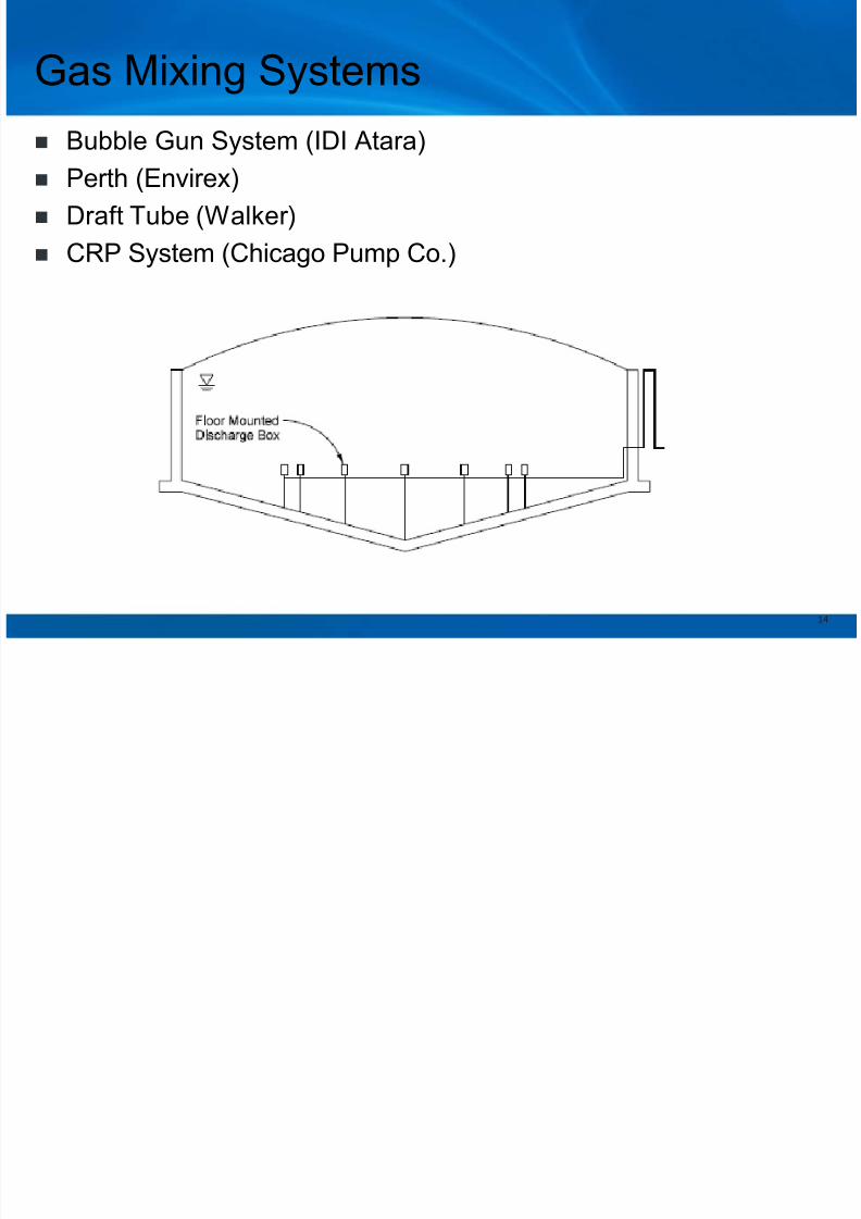
Gas Mixing Systems
Bubble Gun System (IDI Atara) Perth (Envirex)
Draft Tube (Walker)
CRP System (Chicago Pump Co.)
14

8/11/2019 Williams Todd
http://slidepdf.com/reader/full/williams-todd 15/50
Gas Mixing Systems
Advantages o f Gas Mix ing
Most commonly used mixing system
Mixing intensity regulated by throttling gas flow
Complete mixing possible with unconfined gas mixing systems, butonly IDI Atara will guarantee performance
Potentially less power consumption than mechanical mixing systems
Disadvantages of Gas Mixing Gas compressors, nozzles, and diffusers prone to plugging
Excessive foaming and grit accumulation experienced
Explosive characteristics of digester gas (O&M more difficult)
Costly retrofit for existing digesters (addition of gas compressors andpiping)
Inefficient mixing below gas injection level prevents grit from remainingin suspension
System requires maintenance of “different” types of equipment –compressors, etc.
Proprietary mixing systems
15

8/11/2019 Williams Todd
http://slidepdf.com/reader/full/williams-todd 16/50
Mixing Parameters in Digesters
GER (Gas Evolution Rate) – is driven by microbiological activity:
– Area-specific as gas always rises (Mixing Energy/area-time)
– Increases with greater height to diameter ratio
RRFR (Rapid Rise Foam Formation Rate) is driven by
– GER (Gas Evolution Rate)
– Mechanical MEI (Mixing Energy input)
Each sludge and digester design is a unique combination and
present a unique set of circumstances.
16

8/11/2019 Williams Todd
http://slidepdf.com/reader/full/williams-todd 17/50
Where’s the Mixing Energy Sweet Spot?
Mixing Energy Input
R
R
F
R
GER Over-Mixing Zone
RRFR = Rapid Rise Foam Formation Rate
GER = Gas Evolution Rate
Here?
17

8/11/2019 Williams Todd
http://slidepdf.com/reader/full/williams-todd 18/50
Key Points on Digester Mixing
Gas evolution rate increases in proportion to mixing energy input
Digester over-mixing is a wide-spread concern and contributes tofoam production.
More work and more detailed information required to selectappropriate digester mixing systems.
Better performance results from feeding digesters as continuous aspossible, especially with FOG and high-strength organic wastesadded to the feed.
Can expect to see
– More pumped hydraulic jet mixing systems with VFDs (variablefrequency drives)
– LMMs as a path forward.
– Different energy for process needs with grit suspension. Grit removal+ LMM may become more common.
18

8/11/2019 Williams Todd
http://slidepdf.com/reader/full/williams-todd 19/50Copyright 2013 by CH2M HILL, Inc. •al
W B G 0 6 2 2 1 1 1 2 1 2 4 5 O R L
Digester Overflows – Causes and Control Measures

8/11/2019 Williams Todd
http://slidepdf.com/reader/full/williams-todd 20/50
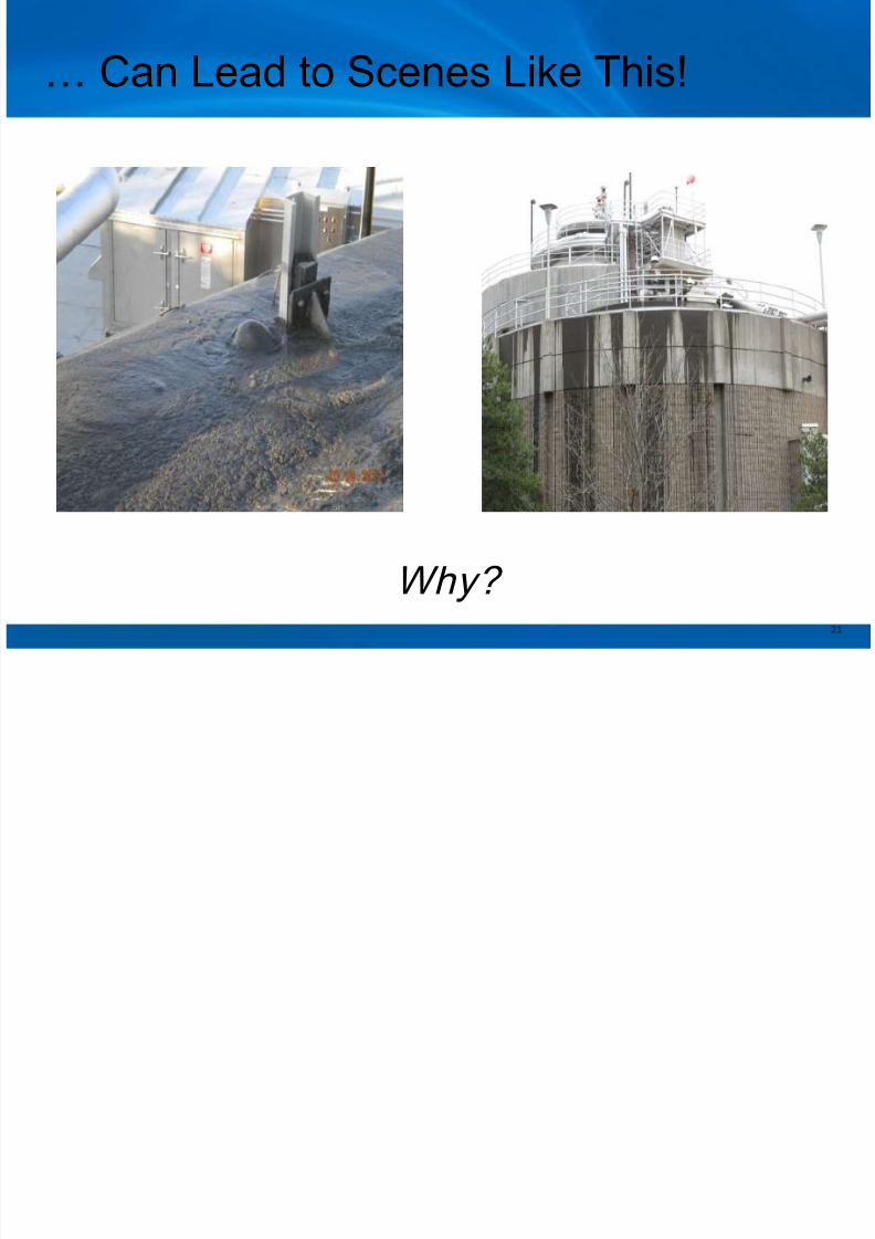
Volume Expansion & Density Reductionfrom Gas Holdup
20
8/11/2019 Williams Todd
http://slidepdf.com/reader/full/williams-todd 21/50
… Can Lead to Scenes Like This!
Why? 21

8/11/2019 Williams Todd
http://slidepdf.com/reader/full/williams-todd 22/50
Factors with Volume Expansion
Potential Causes
Changes in rate or
composition of feed
Changes in mixing
regimen
Power outage/shutoff of
mixing
Inadequate or excessive
heating
Rapid pressure drops
Potential Safeguards
Pressure relief valves
Emergency surfaceoverflows
Foam suppression sprays
Increased headspace ingas plenum
Rapid transfer piping to
lower liquid level
Note that some of the safeguards are
nonfunctional at reduced liquid density 22

8/11/2019 Williams Todd
http://slidepdf.com/reader/full/williams-todd 23/50
Rapid Rise Foam Formation Event
Flow
Rate
Duration,
hours
Flow Reduction
starts after
Shutoff of Feed
Declining
Leg of EventRising
Leg of
Event
23

8/11/2019 Williams Todd
http://slidepdf.com/reader/full/williams-todd 24/50
Rapid Rise vs. Chronic Foaming
Rapid-rise foaming:
– Frothy sludge with high gas holdup can reduce thedensity to half that of sludge.
– Rapid increase in flow rate (as much as 10-fold morethan inflow)
– Rapid increase signals operation reaction – Extended decrease in the flow rate that can last aslong as a day
– Digesters usually not designed to accommodate
Chronic or normal foaming: – A relatively continuous phenomenon
– Digesters are typically designed to handle chronic ornormal foaming using such measures as foambreakers with scum nozzles
24

8/11/2019 Williams Todd
http://slidepdf.com/reader/full/williams-todd 25/50
Foam Breaker with Scum Nozzle
Vaughan Foambuster (Above) and Scum Nozzle
(Below) for control of surface scum and foam buildup
25

8/11/2019 Williams Todd
http://slidepdf.com/reader/full/williams-todd 26/50
Foam Management Begins with Start-Up
Start-up is a time of transition Transitions are the most critical periods for foam formation
generating gas hold-up
A proven example start-up protocol is found in the WPCF (now
WEF) MOP 16 “Anaerobic Digestion Manual of Practice No.
16”.
This document addresses the start-up procedures and is crystal
clear on what is required.
26
8/11/2019 Williams Todd
http://slidepdf.com/reader/full/williams-todd 27/50
Digestion Process Start-Up
MOP 16 and common sense dictate that all systems and
equipment must be operational before startup.
The monitoring program and laboratory capacity must be ready to
go.
The staff must be fully trained. A contingency plan must be in place.
One person must be in charge
Everyone must buy in to the challenges.
27

8/11/2019 Williams Todd
http://slidepdf.com/reader/full/williams-todd 28/50
The alternative outlets for gas & liquid ..
Pressure Relief Valve
& Flame Arrester Emergency
Overflow
Can be rendered non-functional due to frothy sludge 28

8/11/2019 Williams Todd
http://slidepdf.com/reader/full/williams-todd 29/50
Gas Draw-Off Pipe
Can be part of the cause of an imbalanced loading 29

8/11/2019 Williams Todd
http://slidepdf.com/reader/full/williams-todd 30/50
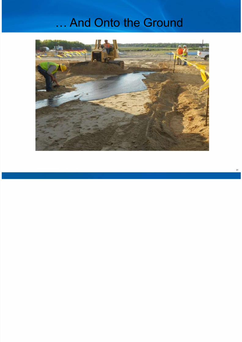
Frothy Sludge Over the Digester Wall…
30
8/11/2019 Williams Todd
http://slidepdf.com/reader/full/williams-todd 31/50
… And Onto the Ground
31

8/11/2019 Williams Todd
http://slidepdf.com/reader/full/williams-todd 32/50
Control Measures
Have an approved start-up plan with buy-ins
Have a start-up team with a chain of command that means
business
Avoid premature start-up at all cost.
Avoid complacency at all cost
Visit other sites where start-ups have been done and capture the
lessons learned.
32

8/11/2019 Williams Todd
http://slidepdf.com/reader/full/williams-todd 33/50
Copyright 2013 by CH2M HILL, Inc. •al
W B G 0 6 2 2 1 1 1 2 1 2 4 5 O R L
Addition of FOG and HSW Considerations

8/11/2019 Williams Todd
http://slidepdf.com/reader/full/williams-todd 34/50
FOG and HSW Addition Considerations
Overall Benefits of Use of FOG as a Resource
– Improve sewer and WRRF performance
– Provides revenue stream from tip fees
– Will generate significant amounts of biogas at low hydraulic loading
in anaerobic digestion
– Biogas production when coupled with co-generation can result insignificant cost savings
– Biogas use from FOG addition in CHP can reduce GHG footprint and
energy dependence
Other Considerations
– Get a handle on quantities and characteristics available
– Start slow
– Modeling digester performance/biogas production can easily be done
– Consider impact on entire wwtp process train during design
34
8/11/2019 Williams Todd
http://slidepdf.com/reader/full/williams-todd 35/50
Key Considerations for Utilizing FOGResources
Characteristics and form of FOG or high strengthwastes to be received for co-digestion
Reliability, consistency and availability of each
material supply as a feedstock Collection network to move the FOG to a receiving
station at the WRRF
Special requirements for receiving, holding and
transferring FOG on a continuous basis
35

8/11/2019 Williams Todd
http://slidepdf.com/reader/full/williams-todd 36/50
Key Considerations for Utilizing FOGResources
Capacity available or required in each supportingsystem of the solids train
Additional return liquor loadings
Excess capacity in the liquid treatment train or separateside stream treatment system to handle the additional
return liquor loadings Synergistic sludge degradation with FOG addition can
potentially increase the recycled nutrients load
There can be significant net cost savings despite theextra cost of treating the higher strength recycle streams
36
Key Considerations for Utilizing FOG

8/11/2019 Williams Todd
http://slidepdf.com/reader/full/williams-todd 37/50
Key Considerations for Utilizing FOGResources
Using digester gas to fuel CHP projects is a rapidly growingpractice to reduce energy demand at WRRFs with anaerobic
digestion systems.
Receiving FOG and HSW into WRRFs with spare digestion
capacity can create revenue by tipping fees and boost gasproduction, thereby making CHP more economically attractive than
digesting biosolids alone.
The manner in which FOG and HSW are received at a WRRF and
fed to digesters is critical to avoid digestion upsets.
Heated storage tanks for blending and leveling out FOG/HSW feed
rates to digesters are critical elements of any FOG/HSW receiving
facility.
37
S ( ti d)

8/11/2019 Williams Todd
http://slidepdf.com/reader/full/williams-todd 38/50
Summary (continued)
There is little in the way of standard operating procedures for thesetypes of facilities to date, but the practice is growing sufficiently that
development of standard procedures and best practices is warranted.
Procedures are being implemented at many facilities that will be
useful to operators of other FOG/HSW receiving facilities, and willcontribute to industry standards as they are developed
The construction of CHP systems along with FOG and HSW receiving
and handling systems can offer attractive payback periods in the
range of 4 to 9 years, even in locations with relatively low unit powerrates. Site-specific issues such as tipping fees and power-rate
structure will affect lifecycle costs and payback period.
38

8/11/2019 Williams Todd
http://slidepdf.com/reader/full/williams-todd 39/50
Summary of Means to Avoid Problems
Feed consistently (hourly at least)
Ramp up feed loading slowly based on solids/COD load
Make sure characteristics of FOG/HSW feed materials are known
– COD
– pH
– Nutrient content Monitor digester conditions daily
– Alkalinity
– pH
– VFA’s
Consider adding fixed covers with gas collection bonnet in thedome with foam suppression
Consider pre-heating FOG/HSW before feeding to digester
Consider pre-blending FOG/HSW with thickened primary solidsand WAS before feeding to the digester
39
8/11/2019 Williams Todd
http://slidepdf.com/reader/full/williams-todd 40/50
Copyright 2013 by CH2M HILL, Inc. •al
W B G 0 6 2 2 1 1 1 2 1 2 4 5 O R L
FOG and HSW Addition to Digesters withCombined heat and Power System
Case Studies
F iliti

8/11/2019 Williams Todd
http://slidepdf.com/reader/full/williams-todd 41/50
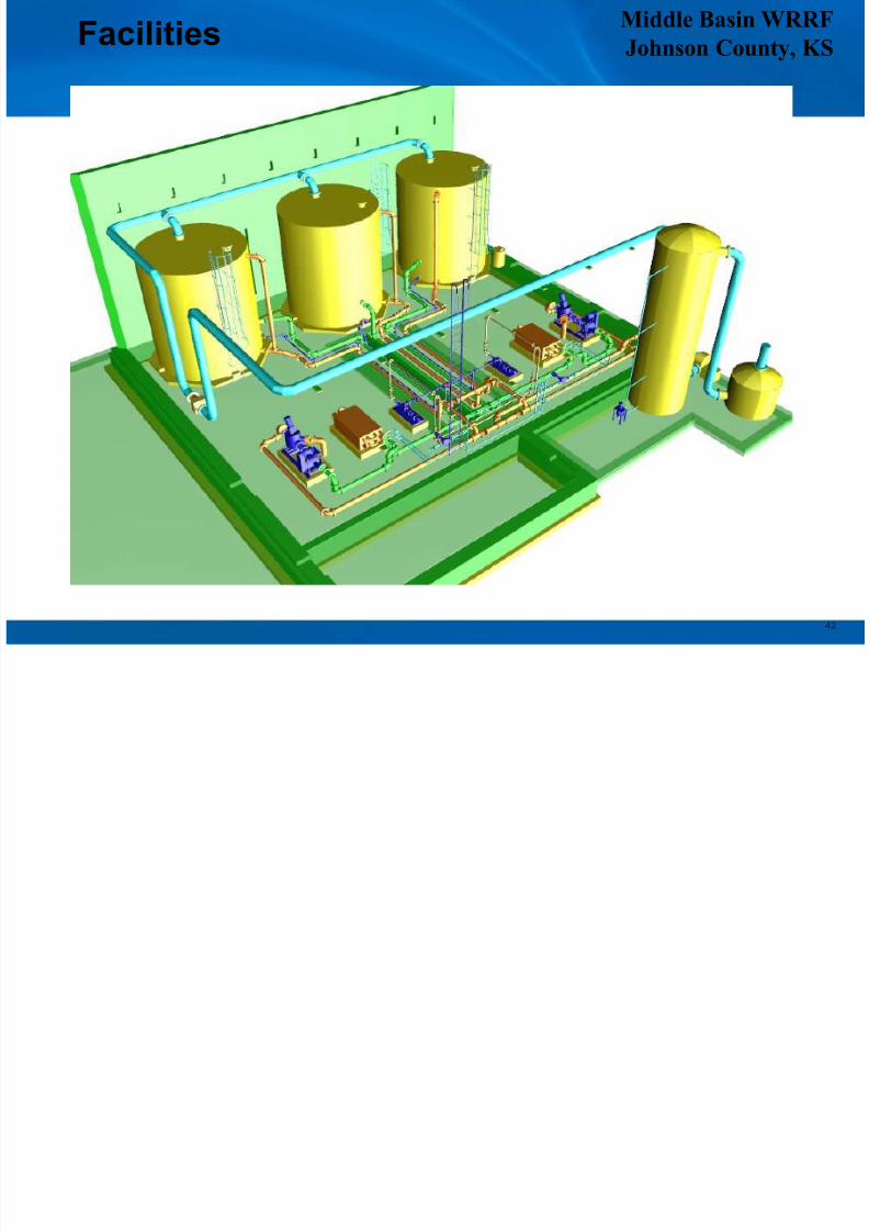
Facilities
41
Smith Middle Basin WRRF 35-mgd (132,000 m3/day)
capacity WRRF
FOG/HSW receiving facility toprocess 14,500 gal/day (55m3/day) on average
Cold winter & snow requiresbuilding enclosure & heatedtanks
Multiple day tanks, heatingand equalization systems
Two 1.06 megawatt (MW)internal combustion engines(ICE)
Middle Basin WRRFFacilities
8/11/2019 Williams Todd
http://slidepdf.com/reader/full/williams-todd 42/50
Johnson County, KSFacilities
42
F iliti
8/11/2019 Williams Todd
http://slidepdf.com/reader/full/williams-todd 43/50
Facilities
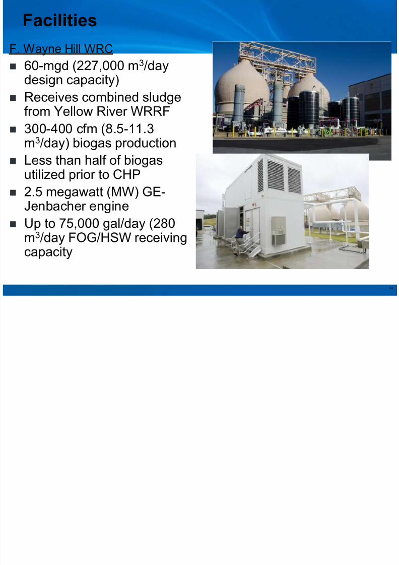
F. Wayne Hill WRC
60-mgd (227,000 m
3
/daydesign capacity)
Receives combined sludgefrom Yellow River WRRF
300-400 cfm (8.5-11.3
m3/day) biogas production Less than half of biogas
utilized prior to CHP
2.5 megawatt (MW) GE-
Jenbacher engine Up to 75,000 gal/day (280
m3/day FOG/HSW receivingcapacity
43
Facilities

8/11/2019 Williams Todd
http://slidepdf.com/reader/full/williams-todd 44/50
FWH-WRC
FOG/HSW and CHP
system
Gwinnett County, GA
Facilities
44
Biogas with Addition of Fats, Oil

8/11/2019 Williams Todd
http://slidepdf.com/reader/full/williams-todd 45/50
Biogas with Addition of Fats, Oil& Grease (FOG)
50 dry tons/day solids > 600,000 ft3/day of
biogas $4,800/day energy value
55,000 gal/day FOG @ 5% solids + 50 dry
tons/day solids > 952,000 ft3/day of biogas
$7,600/day energy value
+ $1,022,000/yr energy value with FOG
F. Wayne Hill WRC, Gwinnett County, Georgia
Douglas L. Smith Middle Basin Facility
Johnson County, Kansas
50% of Plant Power Needs Met
45
8/11/2019 Williams Todd
http://slidepdf.com/reader/full/williams-todd 46/50
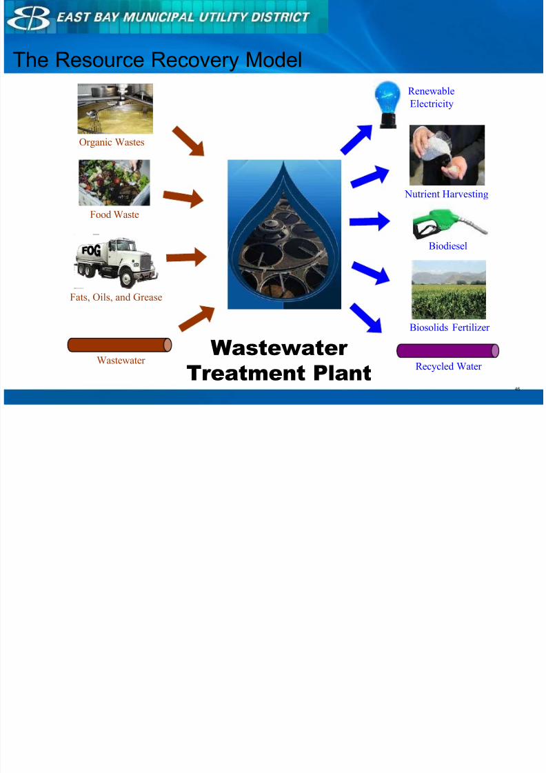
The Resource Recovery Model
Biosolids Fertilizer
Biodiesel
Renewable
Electricity
Recycled Water Wastewater
Organic Wastes
Food Waste
Fats, Oils, and Grease
Wastewater
Treatment Plant
Nutrient Harvesting
46

8/11/2019 Williams Todd
http://slidepdf.com/reader/full/williams-todd 47/50
Renewable Energy Expansion
Installed in 1985
Meet 40-50% of demand(2-2.5 MW net gen) Frequent flaring of excess
biogas
Expansion
(+1 turbine)
• Meet 100-200% of demand(5-10 MW net gen)
• Sell excess green energy• Reduce air and GHG
emissions
• Increase operationalreliability
Original Facility(3 engines)
47

8/11/2019 Williams Todd
http://slidepdf.com/reader/full/williams-todd 48/50
First WWTP in U.S. to Become a Net Electricity Provider
2013 to-date
Generation: 6MW
Demand: 5MW
Net Sales = 1MW
ElectricalGrid
Wastewater
Treatment Plant
Net Electricity Provider
48
Resource Recovery Opportunities

8/11/2019 Williams Todd
http://slidepdf.com/reader/full/williams-todd 49/50
Copyright 2013 by CH2M HILL, Inc.
Resource Recovery OpportunitiesRemember 3-3-6!
3 Times as many WRRF’s are without AD as those with AD
3 Times as many WRRF’s with AD do not generate power or
drive plant equipment as those that do
6 Times as many WRRF’s do not import FOG or high strength
waste to feed digesters as those that do
49
Anaerobic Digestion and

8/11/2019 Williams Todd
http://slidepdf.com/reader/full/williams-todd 50/50
Anaerobic Digestion andCo-Digestion Optimization
QUESTIONS?
Todd Williams, PE, BCEE