williams et al. supplemental material 1
TRANSCRIPT

Williams et al. Supplemental Material
1
Field guide to exhumed paleochannels near Green River, Utah: Terrestrial analogs for sinuous ridges on Mars
Rebecca M. E. Williams1, Rossman P. Irwin III1, James R. Zimbelman2, Thomas C. Chidsey, Jr.3, David E. Eby4
1Planetary Science Institute, 1700 East Fort Lowell Rd., Suite 106, Tucson, AZ 85179
2Center for Earth and Planetary Studies, National Air and Space Museum, Smithsonian Institution, Independence Ave. at Sixth St. SW,
MRC 315, Washington, DC 20013-7012 3Utah Geological Survey, P. O. Box 146100, Salt Lake City, UT 84114-6100
4Eby Petrography and Consulting, 2830 W. 9th Ave. Denver, CO 80204.
SUPPLEMENTAL MATERIALS
Supplemental Figures in Color and Black & White p. 2-16
SUPPLEMENTAL FIGURES For all photomicrographs, the following key is used: PL = Plain Light; XN = Crossed Nicols; AP = Gypsum Accessory Plate; ND = Neutral Density filter.

Williams et al. Supplemental Material
2
Supplemental Figure 1. Paleogeographic map of Utah during Ruby Ranch time (Aptian to middle Albian) with Sevier orogenic belt in western Utah and various fluvial depositional environments present in east-central Utah (Figure from Williams et al., 2007b, modified from Elder and Kirkland, 1993; Kirkland et al., 1998).
Williams et al. Supplemental Material
3
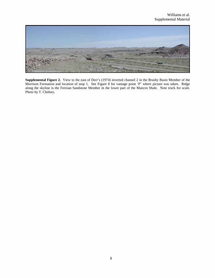
Supplemental Figure 2. View to the east of Derr’s (1974) inverted channel 2 in the Brushy Basin Member of the Morrison Formation and location of stop 1. See Figure 8 for vantage point ‘P’ where picture was taken. Ridge along the skyline is the Ferroan Sandstone Member in the lower part of the Mancos Shale. Note truck for scale. Photo by T. Chidsey.

Williams et al. Supplemental Material
4
Supplemental Figure 3. A) Negative relief valley network (top of image) transitions to a low relief plateau (sinuous ridge at bottom) near 32̊ N, 314˚ W in Arabia Terra. White box marks location of panel B. Illuminati on from the lower left in this subscene of CTX image P15_006990_2127. B) Subscene of HiRISE image PSP_005355_2125 showing transition zone. Illumination is from the left (note impact crater at upper right in panel B). Image modified from original NASA/JPL/University of Arizona.

Williams et al. Supplemental Material
5
Supplemental Figure 4. A) View to the west from a nearby hill where two low-relief (<2 m) inverted channels are marked by black and white arrows. See Figure 8 for vantage point ‘P’ where the picture was taken. The San Rafael Swell is in the background. Width of scene at the location of the black arrows is ~0.5 km. Photo by T. Chidsey. B) Ground-based photo of same site shows that the surface expression of these inverted channels (marked by white and black arrows) is very subtle. Photo by R. Williams.
Williams et al. Supplemental Material
6
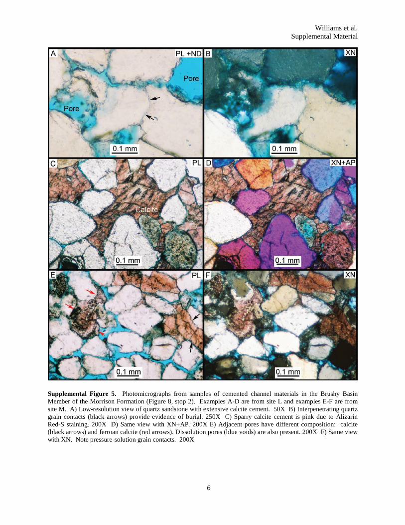
Supplemental Figure 5. Photomicrographs from samples of cemented channel materials in the Brushy Basin Member of the Morrison Formation (Figure 8, stop 2). Examples A-D are from site L and examples E-F are from site M. A) Low-resolution view of quartz sandstone with extensive calcite cement. 50X B) Interpenetrating quartz grain contacts (black arrows) provide evidence of burial. 250X C) Sparry calcite cement is pink due to Alizarin Red-S staining. 200X D) Same view with XN+AP. 200X E) Adjacent pores have different composition: calcite (black arrows) and ferroan calcite (red arrows). Dissolution pores (blue voids) are also present. 200X F) Same view with XN. Note pressure-solution grain contacts. 200X

Williams et al. Supplemental Material
7
Supplemental Figure 6. Several examples of outcrop exposures at the base of paleochannels in the Ruby Ranch Member. A) In channel D, muddy deposits are protected by overlying channel deposits, forming an overhang in the picture. Green and yellow-brown mudstone subjacent to the channel base formed in a reducing environment at the channel-floodplain interface. Photo by R. Williams. B) In places, there are large (~50 cm diameter) limestone rip-up clasts, likely lacustrine deposits that were reworked during high flow events. This example is from channel A. Photo by J. Zimbelman. C) Elsewhere the base of channel D is marked by a basal conglomerate with pedogenic carbonate nodules up to 10 cm in diameter; a similar basal conglomerate is observed elsewhere in the Cedar Mountain Formation to the north (Currie, 1998). Photo by R. Williams.

Williams et al. Supplemental Material
8
Supplemental Figure 7.
Williams et al. Supplemental Material
9
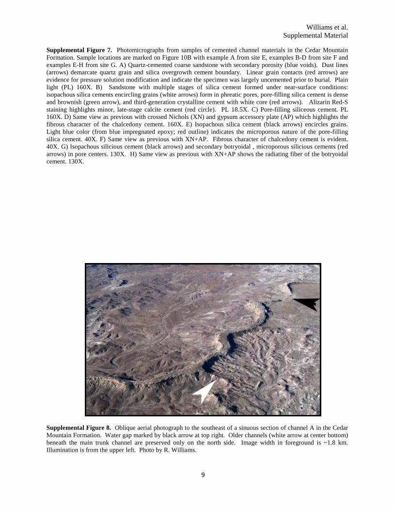
Supplemental Figure 7. Photomicrographs from samples of cemented channel materials in the Cedar Mountain Formation. Sample locations are marked on Figure 10B with example A from site E, examples B-D from site F and examples E-H from site G. A) Quartz-cemented coarse sandstone with secondary porosity (blue voids). Dust lines (arrows) demarcate quartz grain and silica overgrowth cement boundary. Linear grain contacts (red arrows) are evidence for pressure solution modification and indicate the specimen was largely uncemented prior to burial. Plain light (PL) 160X. B) Sandstone with multiple stages of silica cement formed under near-surface conditions: isopachous silica cements encircling grains (white arrows) form in phreatic pores, pore-filling silica cement is dense and brownish (green arrow), and third-generation crystalline cement with white core (red arrows). Alizarin Red-S staining highlights minor, late-stage calcite cement (red circle). PL 18.5X. C) Pore-filling siliceous cement. PL 160X. D) Same view as previous with crossed Nichols (XN) and gypsum accessory plate (AP) which highlights the fibrous character of the chalcedony cement. 160X. E) Isopachous silica cement (black arrows) encircles grains. Light blue color (from blue impregnated epoxy; red outline) indicates the microporous nature of the pore-filling silica cement. 40X. F) Same view as previous with XN+AP. Fibrous character of chalcedony cement is evident. 40X. G) Isopachous silicious cement (black arrows) and secondary botryoidal , microporous silicious cements (red arrows) in pore centers. 130X. H) Same view as previous with XN+AP shows the radiating fiber of the botryoidal cement. 130X.
Supplemental Figure 8. Oblique aerial photograph to the southeast of a sinuous section of channel A in the Cedar Mountain Formation. Water gap marked by black arrow at top right. Older channels (white arrow at center bottom) beneath the main trunk channel are preserved only on the north side. Image width in foreground is ~1.8 km. Illumination is from the upper left. Photo by R. Williams.
Williams et al. Supplemental Material
10
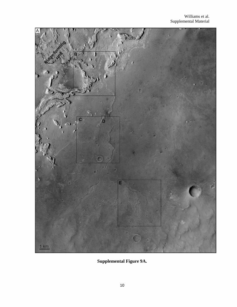
Supplemental Figure 9A.

Williams et al. Supplemental Material
11
Supplemental Figure 9. A) Branching landform in Meridiani Planum that exhibits variations in preservation style from positive to negative relief. Black boxes in A are Enlargement of subscenes from panel A are presented in panels B-E. Northern portion of system (B), presumably the downstream section, is buried beneath rock layers (black arrow). The landform transitions from positive relief (low-relief ridge marked by black arrow) to negative relief trough (white arrows in C) that has a medial ridge in places. The southern portion of the landform is marked by a series of aligned pits that trace out the branching pattern (E). At higher resolution (D), the stratigraphic relationship is evident with the low-relief, light-toned ridge (the inverted channel) capped by a narrow band of the former overburden. The cracked pattern on the light-toned ridge and superposing material (cracks are sometimes traverse across the two materials, marked by black arrows) differ in size and configuration from the polygonal pattern on the surrounding plains. Panels A-C and E are subframes of CTX image P03_002390_1840 near 4.6̊ N, 1.3˚ W. Panel D is subframe of HiRISE PSP_004091_1845. Illumination is from left for all images.

Williams et al. Supplemental Material
12
Supplemental Figure 10. Oblique aerial photograph of two channel segments in the Cedar Mountain Formation looking northward, at the location near the labels F and G in Figure 10. The apparent bifurcation marked by black arrows is actually two segments at two different topographic and stratigraphic levels. The inverted paleochannel segment from top to bottom (north to south, segment D) in image is stratigraphically higher than the paleochannel segment that extends to the right (westernmost section of segment B). Scale bar is for image foreground. The Late Cretaceous Book Cliffs (e.g. Young, 1955), which form the northern rim of the Colorado Plateau in eastern Utah, are visible in the background. Photo by R. Williams.

Williams et al. Supplemental Material
13
Supplemental Figure 11. A) Sinuous ridges in the Aeolis/Zephyria Plana region immediately east of the location in Figure 6. Black boxes are approximate regions enlarged in panels B and C, which show areas where eolian erosion has modified former sinuous ridges into aligned knobs and mesas (black arrows). Subframe of CTX image P03_002081_1751 is located near 5˚ S, 205˚ W. Illumination is from lower left.

Williams et al. Supplemental Material
14
Supplemental Figure 12. A) Examples of degradation along sections of inverted paleochannels in the Ruby Ranch Member of the Cedar Mountain Formation. Erosion exploits the joints and faults in the paleochannels, producing blocks of cemented channel sediments. Blocks that have been transported downslope by mass wasting are marked by white circles. Differential erosion is also evident, with the underlying mudstone preferentially removed from beneath the more resistant paleochannels caprock; this undermining produces alcoves (red arrow). B) Cemented fluvial sediments form a capstone (white arrow). Where the capstone has been removed, the underlying mudstone still marks the original flow path (in this case curing around to the lower right in the image).

Williams et al. Supplemental Material
15
Supplemental Figure 13. Photomicrographs from samples of cemented channel materials in the Salt Wash Member of the Morrison Formation (stop 7; Figure 12). A) Quartz sandstone with silica overgrowth cements and minor calcite (red due to Alizarin Red-S stain) cement in plain light with neutral density filter. 50X. B) Same view as in previous figure with XN. 50X C) Sparry calcite (red) and silica cement around detrital quartz grains. 160X. D) Same view as in previous figure. 160X. E) Close-up view of dust lines (arrows) separating grains from silica cement. 200X. F) Same view as in previous figure. Optical continuity between grain and cement is evident under XN. 200X.

Williams et al. Supplemental Material
16
Supplemental Figure 14. View of the contact between cemented fluvial deposits and underlying red floodplain materials within the Salt Wash Member of the Morrison Formation. The capstone margin is near vertical and cut by fractures. Approximate outcrop thickness is 2.5 m. Photo by R. Williams.