williams, c., mclaughlin, s., & beach, m. a. (2009
TRANSCRIPT

Williams, C., McLaughlin, S., & Beach, M. A. (2009). Exploiting multipleantennas for synchronization. IEEE Transactions on Vehicular Technology,58(2), 773 - 787. 10.1109/TVT.2008.925309
Link to published version (if available):10.1109/TVT.2008.925309
Link to publication record in Explore Bristol ResearchPDF-document
University of Bristol - Explore Bristol ResearchGeneral rights
This document is made available in accordance with publisher policies. Please cite only the publishedversion using the reference above. Full terms of use are available:http://www.bristol.ac.uk/pure/about/ebr-terms.html
Take down policy
Explore Bristol Research is a digital archive and the intention is that deposited content should not beremoved. However, if you believe that this version of the work breaches copyright law please [email protected] and include the following information in your message:
• Your contact details• Bibliographic details for the item, including a URL• An outline of the nature of the complaint
On receipt of your message the Open Access Team will immediately investigate your claim, make aninitial judgement of the validity of the claim and, where appropriate, withdraw the item in questionfrom public view.
brought to you by COREView metadata, citation and similar papers at core.ac.uk
provided by Explore Bristol Research

IEEE TRANSACTIONS ON VEHICULAR TECHNOLOGY, VOL. 58, NO. 2, FEBRUARY 2009 773
Exploiting Multiple Antennas for SynchronizationChris Williams, Member, IEEE, Stephen McLaughlin, Senior Member, IEEE, and Mark A. Beach, Member, IEEE
Abstract—Orthogonal frequency-division multiplex (OFDM)offers a low-complexity solution to equalization in multipath chan-nels but does so by increasing the symbol period. This places alimit on the mobility of such systems since time variations in thechannel during the symbol period introduce intercarrier interfer-ence (ICI), hence, degrading performance. Solutions to reduce ICIin the literature require a high degree of processing. Increasingterminal mobility also places greater requirements on synchro-nization processing to track the rapidly changing channel. Thispaper uses multiple antennas at the receiver so that the channelresponse can be decomposed into a number of more slowly varyingchannels. Independent synchronization processing and correctioncan be applied to each of the derived channels before combiningthe signals prior to the fast Fourier transform (FFT) process.By individually processing the channels, the effective channel iscompressed in the time and frequency domains, improving systemperformance. Perfect tracking of the multipath clusters is initiallyassumed to show the potential benefits, followed by operation withan idealized tracking algorithm. Operation with more realisticprocessing algorithms using fixed sectored elements improvingthe bit error rate (BER) is investigated. Finally, the benefits arethen demonstrated with real measured channels from an urbanenvironment.
Index Terms—Antenna arrays, digital communications, DigitalVideo Broadcasting (DVB), orthogonal frequency-division multi-plex (OFDM), synchronization.
I. INTRODUCTION
O RTHOGONAL frequency-division multiplex (OFDM)offers a low-complexity solution to equalization in mul-
tipath channels but does so by increasing the symbol period.This places a limit on the mobility of such systems since timevariations in the channel during the symbol period introduceintercarrier interference (ICI), hence, degrading performance.Solutions to reduce ICI reported in the literature require a sig-nificant degree of processing, and increasing terminal mobilityalso places greater requirements on synchronization processingto track the rapidly changing channel. In this paper, a method
Manuscript received August 16, 2006; revised June 6, 2007, December 14,2007, February 14, 2008, and March 20, 2008. First published May 14, 2008;current version published February 17, 2009. This work was supported in partby the Virtual Centre of Excellence in Mobile and Personal Communications(Mobile VCE) and in part by the Engineering and Physical Sciences ResearchCouncil. The review of this paper was coordinated by Prof. L. Lampe.
C. Williams was with the University of Bristol, Bristol BS8 1TR, U.K. Heis now with Fujitsu Laboratories of Europe, Hayes UB4 8FE, U.K. (e-mail:[email protected]).
S. McLaughlin is with the School of Engineering and Electronics, Uni-versity of Edinburgh, Edinburgh EH9 3JL, U.K. (e-mail: [email protected]).
M. A. Beach is with the Department of Electrical Engineering, University ofBristol, Bristol BS8 1TR, U.K. (e-mail: [email protected]).
Color versions of one or more of the figures in this paper are available onlineat http://ieeexplore.ieee.org.
Digital Object Identifier 10.1109/TVT.2008.925309
is proposed to use multiple antennas at the receiver so that thechannel response can be decomposed into a number of moreslowly varying channels. Independent synchronization process-ing and correction can then be applied to each of the derivedchannels before combining the signals prior to the fast Fouriertransform (FFT) process. Previously in the literature, it has beensuggested that there would be benefits in slowing the rate ofchannel variation [1], [2], but there has been no implementa-tion where prior knowledge of channel and/or synchronizationparameters was not assumed. The contribution of this paper is todemonstrate the performance improvement in a realistic systemwithout prior knowledge of channel parameters.
In this paper, the terrestrial Digital Video Broadcast(DVB-T) system is used as an example of an OFDM system. Inall cases presented, synchronization parameters for timing andfrequency are estimated from the received signal. The processesinvolved can be summarized as follows:
1) separation of the received signal into clusters1 throughspatial discrimination;
2) synchronization parameter estimation per cluster (timingand frequency);
3) synchronization correction;4) signal combining of the synchronized clusters into a
single signal for detection.
In this paper, combining takes place before the OFDM FFTprocess, and thus, the overall complexity is low. Frequencycorrection is applied to each cluster before combining, andtherefore, the postcombining Doppler spread is bounded by theDoppler spread of each cluster, which is lower than that with asingle antenna. The effect of timing correction both before andafter the combining process is also investigated.
In this paper, the cases of full and no prior information of themultipath channel spatial characteristics at the receiver are alsoconsidered. While, in theory, being able to estimate and trackthe channel spatial response should ultimately offer signifi-cant performance benefits, in practice, errors in the estimationprocess will degrade performance. A fixed sector approach of-fers an effective low-complexity solution, and such an approachis proposed here. In addition to the synthetic channels, theeffective use of sectored antennas is demonstrated using datameasured in an urban channel with a single transmitter.
The results presented here demonstrate that timing correctionbefore combining is generally most effective, but in somecases, a hybrid approach that can switch between precom-bining timing correction (pre-CTC) and postcombining timing
1In any practical system, the arriving multipath signals will form clustersbased on the propagation characteristics of the channel [10]–[15]. In this paper,a cluster is defined as a group of waves with similar delay and angles of arrivalin azimuth and elevation, as discussed in [10].
0018-9545/$25.00 © 2009 IEEE
Authorized licensed use limited to: UNIVERSITY OF BRISTOL. Downloaded on October 5, 2009 at 09:12 from IEEE Xplore. Restrictions apply.
774 IEEE TRANSACTIONS ON VEHICULAR TECHNOLOGY, VOL. 58, NO. 2, FEBRUARY 2009
correction (post-CTC) is better. It is also shown that pre-CTCis effective when the delay spread exceeds the cyclic prefix(CP) length. Therefore, the method of pre-CTC proposed in thispaper provides compression of the effective channel in the timeand frequency domains (lower delay spread and lower Dopplerspread). It is shown that, although energy may be split be-tween multipath clusters, thus lowering the signal-to-noise ratio(SNR) on each channel, the robustness of the synchronizationestimator results in no overall loss of performance after signalcombination.
This paper is structured as follows: In the next section, detailsregarding the channel are discussed, followed by a review ofpossible system architectures for combining synchronizationand antenna array processing. Then, brief results are presentedfor when the channel spatial characteristics are known, fol-lowed by results without such prior knowledge using fixedsectors. Finally, conclusions regarding the results are drawn.
II. CHANNEL CHARACTERISTICS
A. Underlying Channel Model
The considerable interest in multiple-input–multiple-output(MIMO) systems has resulted in a significant number of paperspublished, which take statistical models and relate them tophysical measurements (e.g., see [12]–[14] among others). Onecharacteristic that is consistent in these papers is the presenceof temporal and spatial clusters, as discussed in [10] and [12].These clusters, as discussed in [12], are related to groups ofarrivals, which are clustered within a narrow time (200 ms)or an angular (3◦–6◦) window. This clustering of multipathcomponents has a variety of plausible physical interpretationsoften related to the geometry of the propagation environment.
The combined impulse response of such channels is de-scribed as
h(t, θ)=∞∑
l=0
∞∑
k=0
{βkle
jθklδ(t−Tl−εkl)δ(θ−θl−ωkl)}
(1)
where Tl and εkl represent the cluster and ray interarrival times,respectively. That is, Tl is the intercluster arrival time, and εkl
is the intracluster arrival time. Likewise, θl and ωkl representthe cluster and ray angle of arrival terms, respectively. Theliterature discusses suitable distributions for these parameters,and this is discussed later in this paper as the synchronizationmethod is developed.
B. Simulation Channel Model
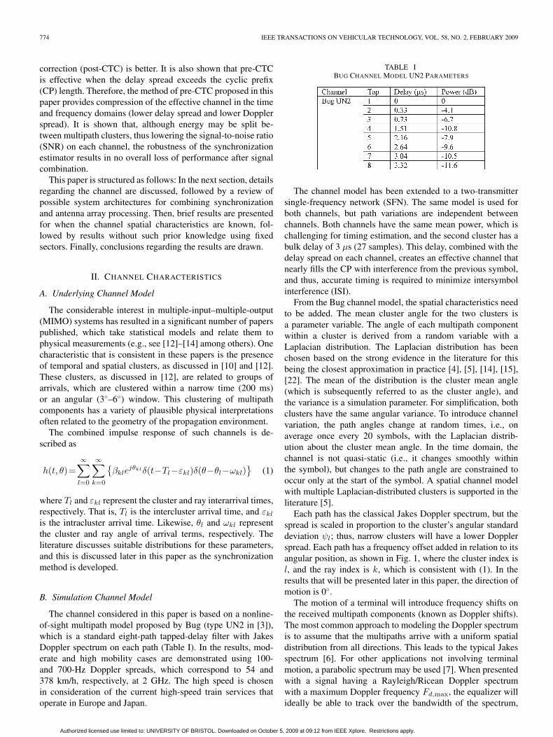
The channel considered in this paper is based on a nonline-of-sight multipath model proposed by Bug (type UN2 in [3]),which is a standard eight-path tapped-delay filter with JakesDoppler spectrum on each path (Table I). In the results, mod-erate and high mobility cases are demonstrated using 100-and 700-Hz Doppler spreads, which correspond to 54 and378 km/h, respectively, at 2 GHz. The high speed is chosenin consideration of the current high-speed train services thatoperate in Europe and Japan.
TABLE IBUG CHANNEL MODEL UN2 PARAMETERS
The channel model has been extended to a two-transmittersingle-frequency network (SFN). The same model is used forboth channels, but path variations are independent betweenchannels. Both channels have the same mean power, which ischallenging for timing estimation, and the second cluster has abulk delay of 3 μs (27 samples). This delay, combined with thedelay spread on each channel, creates an effective channel thatnearly fills the CP with interference from the previous symbol,and thus, accurate timing is required to minimize intersymbolinterference (ISI).
From the Bug channel model, the spatial characteristics needto be added. The mean cluster angle for the two clusters isa parameter variable. The angle of each multipath componentwithin a cluster is derived from a random variable with aLaplacian distribution. The Laplacian distribution has beenchosen based on the strong evidence in the literature for thisbeing the closest approximation in practice [4], [5], [14], [15],[22]. The mean of the distribution is the cluster mean angle(which is subsequently referred to as the cluster angle), andthe variance is a simulation parameter. For simplification, bothclusters have the same angular variance. To introduce channelvariation, the path angles change at random times, i.e., onaverage once every 20 symbols, with the Laplacian distrib-ution about the cluster mean angle. In the time domain, thechannel is not quasi-static (i.e., it changes smoothly withinthe symbol), but changes to the path angle are constrained tooccur only at the start of the symbol. A spatial channel modelwith multiple Laplacian-distributed clusters is supported in theliterature [5].
Each path has the classical Jakes Doppler spectrum, but thespread is scaled in proportion to the cluster’s angular standarddeviation ψl; thus, narrow clusters will have a lower Dopplerspread. Each path has a frequency offset added in relation to itsangular position, as shown in Fig. 1, where the cluster index isl, and the ray index is k, which is consistent with (1). In theresults that will be presented later in this paper, the direction ofmotion is 0◦.
The motion of a terminal will introduce frequency shifts onthe received multipath components (known as Doppler shifts).The most common approach to modeling the Doppler spectrumis to assume that the multipaths arrive with a uniform spatialdistribution from all directions. This leads to the typical Jakesspectrum [6]. For other applications not involving terminalmotion, a parabolic spectrum may be used [7]. When presentedwith a signal having a Rayleigh/Ricean Doppler spectrumwith a maximum Doppler frequency Fd,max, the equalizer willideally be able to track over the bandwidth of the spectrum,
Authorized licensed use limited to: UNIVERSITY OF BRISTOL. Downloaded on October 5, 2009 at 09:12 from IEEE Xplore. Restrictions apply.

WILLIAMS et al.: EXPLOITING MULTIPLE ANTENNAS FOR SYNCHRONIZATION 775
Fig. 1. Spatial modeling of clusters.
i.e., ±Fd,max. In OFDM, the Doppler shift and spread inthe received signal will introduce ICI between subcarriers.For the DVB-T system investigated in [8] and [9], Dopplerspreads greater than 10% of the subcarrier bandwidth degradeperformance.
A constant Doppler shift can easily be corrected as part ofthe pre-FFT synchronization process, but synchronization doesnothing for a high Doppler spread.
In practice, the arriving signals will form clusters, as previ-ously discussed in this paper, based on the propagation char-acteristics of the channel [10]–[15]. A cluster in this paper isdefined as a group of waves with similar delay and angles ofarrival in azimuth and elevation [10]. In a broadcast system de-ployed as an SFN [11], signals from different transmitters willbe received, and a degree of clustering of multipath componentsfrom each transmitter is expected, particularly in suburbanor rural environments. In a broadcast SFN, the number oftransmitter signals that the terminal can receive may be low andmay have a wide angular separation between clusters.
The existence of multipath clusters in single-transmitter sys-tems (e.g., cellular systems) has been demonstrated through anumber of measurement campaigns [12], [13]. Less than twoor three clusters containing significant power are often seen,with angular spreads less than 20◦. With a nonuniform spatialdistribution, the Doppler spectrum is not expected to be atypical Jakes spectrum [6]. Based on clustering of scatterers, theDoppler spectrum spread for a single cluster is demonstrated in[14] and [15] to reduce as a function of the angular spread andwill have a frequency offset related to the mean cluster angle ofarrival.
Even where discrete clusters are not in evidence, it is possibleto group the multipath components into clusters, such that alarge proportion of the total received power is contained in theunion of those clusters. A previous channel measurement cam-paign has characterized the spatial channel at a mobile terminalin an urban environment [16]. Fig. 2(a) shows one snapshotof the channel characteristics, where each circle correspondsto one multipath component, the position is determined by thepath’s angle of arrival at the terminal and the path time delay,and the size and shade relate to path strength. In this figure,
Fig. 2. Urban channel spatial characteristics and power captured with sectoredantennas. (a) Shade and size of spots relate to power. (b) (Solid) One-sector and(dotted) three-sector beams.
no clear clusters exist. A search procedure was employed withone or three perfect directional beams (i.e., flat response withinthe beam and zero response outside), with beam width as aparameter. Fig. 2(b) shows the proportion of energy containedwithin the optimized beams for different channel snapshots.This demonstrates that only a small number of beams arerequired to capture most of the energy.
The discussion here has focused on channel clusters seenby the terminal. In cellular systems, the high elevation of thebase station (BS) in a macrocell limits the angular spread of thereceived signal on the uplink [18]. In this situation, a single-frequency correction process would be adequate. There havebeen some studies that have demonstrated clustering at the BS[18], and the following analysis may also be relevant to thesesituations.
C. Slowing the Channel
The inability of the equalizer to track the channel and copewith high levels of ICI will limit the mobility of the terminal.To increase the mobility that can be supported, the effectiveDoppler spread needs to be reduced. This is often referred toas “slowing the channel” in the literature [1], [2].
Authorized licensed use limited to: UNIVERSITY OF BRISTOL. Downloaded on October 5, 2009 at 09:12 from IEEE Xplore. Restrictions apply.

776 IEEE TRANSACTIONS ON VEHICULAR TECHNOLOGY, VOL. 58, NO. 2, FEBRUARY 2009
Fig. 3. Reduction of Doppler spread by separation of multipath clusters.
When a single cluster is present, frequency synchronizationwill remove the frequency offset, leaving a much-reducedDoppler spread. When more than one cluster is present, thespatial separation of the clusters can be used to separate them,and then, individual frequency offset corrections are applied tothe individual clusters. This leads to a Doppler spread that is themaximum of the Doppler spreads from the individual clusters.The process is demonstrated in Fig. 3. Since each cluster has anarrow angular spread, the combined Doppler spread is muchreduced.
This could be achieved by employing sectored antennas,with each covering a fixed angular range. A design method todetermine the angular coverage of each antenna, such that theDoppler spread in each antenna is equal, is described in [1].However, such an approach requires knowledge of the channelcharacteristics. In practice, an antenna array could be used toshape beams, but the number of required elements would belarge to give sufficient control, and Nørklit and Vaughan [1]note that performance is a little better than that with equalangular partitioning (sectors). Chizhik [2] develops a methodof receiver beamforming that is based on the channel estimate(beamforming vector) at each antenna. The ideal processorrequires robust channel estimation on each element, and thus,Chizhik proposes to distribute many beams over the expectedangles of arrival, although the vector describing the velocity isstill assumed to be known.
Both [1] and [2] demonstrate successful slowing of thechannel using directional antennas or arrays of antennas; how-ever, knowledge of the channel is assumed, which wouldrequire estimation in practice. Inherent in this approach isthe use of synchronization processing on each of the derivedchannels and then the combination of the corrected signals,which, to our knowledge, has not been demonstrated in theliterature.
Ng and Dubey [19] take the specific case of OFDM anddemonstrate how ICI increases with a higher Doppler spread.A reduction in ICI power is demonstrated when a single di-
rectional antenna and (known) frequency offset is employed.This paper does not discuss angular tracking or frequency offsetestimation.
A novel idea described in [20] is to introduce apparentmovement in the terminals through motion of the antenna,such that the induced directional frequency modulation is suf-ficient to separate multipath components. Antenna movementcan be synthesized by switching (commutating) between arrayelements. Commutation is required to be sufficiently fast toseparate components, and thus, this is likely to work with onlya few widely separated paths; otherwise, dense multipath wouldresult in signals becoming smeared.
D. Discussion
The ability to increase the channel coherence time will allowhigher mobilities to be supported. In practice, this requiresfrequency synchronization to be integrated with antenna arrayprocessing. For most terminals, only a few antennas can beaccommodated, and therefore, processing must be viable forsmall arrays. While beamforming approaches offer the potentialfor higher performance, less-complex processing using fixedsectored antennas is likely to be preferred over the rigid arraygeometry required for beamforming.
Experimental evidence [10]–[15] shows that, temporally, themultipath components within a cluster will have a commontiming offset, which could also be removed on a per-clusterbasis as part of the synchronization process. Thus, the delayspread will be reduced, further improving performance. Indeed,in some situations, received multipath delay spreads greaterthan the OFDM CP period could be tolerated. Previous workon timing estimation [8], [9] improved the estimation of FFTwindow timing, particularly where the first arriving paths wereweak. In this situation, the timing point is delayed, and thus,multipath components arriving before this timing point intro-duce precursor ISI. On the premise that clusters are not onlydistinct in their Doppler spectrum but also have different delay
Authorized licensed use limited to: UNIVERSITY OF BRISTOL. Downloaded on October 5, 2009 at 09:12 from IEEE Xplore. Restrictions apply.

WILLIAMS et al.: EXPLOITING MULTIPLE ANTENNAS FOR SYNCHRONIZATION 777
profiles, timing synchronization per spatial cluster could be aneffective means to solve precursor ISI. Performance benefitswill be achieved where the effective channel response can becompressed in time (lower delay spread) and frequency (lowerDoppler spread).
It should be noted that the proposed concept is not relianton spatial resolution of multipath clusters. Even with a uniformspatial distribution of angles of arrival, partitioning the receivedsignal into sectors would still reduce the rate of channel vari-ation. Where clusters are more tightly focused, greater gainswould be achieved. The greatest mobility challenge is likelyto arise from high-speed transport, where open terrain is mostlikely (e.g., high-speed trains as in Europe and Japan), and thus,spatial separation in such environments is reasonable.
A further benefit will be in SFNs, where oscillator accuracyneeds to be tightly regulated to ensure that ICI is within ac-ceptable limits. When transmitter signals can be discriminated,and therefore separate frequency offsets applied to each, theregulations on oscillator accuracy could be relaxed.
III. SYSTEM ARCHITECTURES
A. System
The exemplar system simulated to illustrate the performanceof the method in this paper is based on the DVB-T standard [21]using the 2k mode with a 64-point CP. The occupied bandwidthis 7.6 MHz. The DVB-T simulator includes the pilot andtransmission parameter signaling (TPS) structures, as defined in[21], including the appropriate pseudonoise sequences. Channelcoding, as defined in [21], has been implemented. The data andTPS information have been produced by random generators. Nopost-FFT synchronization processing has been included (exceptequalization), and thus, the assumption has been made thatno integer frequency offset exists. The equalizer uses linearCartesian interpolation between pilots for channel estimation.
The timing estimation used in this paper is based on thecorrelation-derivative method previously described in [8] and[9]. An outline of the basic algorithm is shown in Table I.Improvement in the performance of this algorithm is possi-ble using the rule heuristics described in [9], which identifypossible bad estimates nest(k) and replace them with a moreconsistent estimate. It should be noted that the purpose of thispaper is to combine the synchronization algorithm with spatialprocessing, and consequently, any alternative synchronizationmethod could be used in practice. Synchronization estimates oftiming and frequency offsets are found for each symbol. The es-timates were then filtered with a 15-point median and 16-pointfinite impulse response filters, as described in Table II. Theprocess for reducing the timing estimate variance described in[9] is enabled. All the algorithms investigated in this section usethe same frequency estimation technique proposed in [22].
B. Architectures for Joint Synchronization andChannel Processing
Different architectures to integrate synchronization and an-tenna processing are possible, where synchronization refers
to timing and frequency offset compensation. The purposeof antenna processing is to separate the received signal intoclusters in the spatial domain, as separation is not possible inthe time or frequency domains due to overlap. Synchronizationestimation is then applied to each derived cluster, giving timingand frequency offsets for each.
In the absence of additional information, frequency cor-rection is applied per cluster based on the estimate for thegiven cluster. With timing correction, there are two possibleapproaches.
1) Per-cluster timing using the estimate for each respectivecluster. After correcting the timing on each cluster, thesignals are then combined. This approach will be calledpre-CTC, as illustrated in Fig. 4. By correcting the timingper cluster, it may be possible to cope with combineddelayed spreads that exceed the CP length. This wouldrequire that the delay spread within each cluster be con-strained to be less than the CP length.
2) The earliest timing estimate across the clusters is ap-plied to all clusters. This approach recognizes that tim-ing estimates could be wrong, and thus, the safestapproach would be to choose the earliest estimate(subject to there being sufficient received power in thecluster, for example, in this paper, 10% of the totalreceived power). This approach is termed post-CTC, asillustrated in Fig. 5. The disadvantage of this methodwill be the additional demands it places on the equal-izer. When long timing delays exist, the rate of phasechange across the subcarriers is greater, and thus, channelestimation by interpolating between pilots becomes lessrobust.
Taking x(t) as the transmitted signal over a P path channelwith each path j having a combined channel and array proces-sor gain of ai,j , Doppler shift of fd,j , and delay of τj [whichis the combination of Tl + εkl from (1)], the output from eachbranch (indexed by i) of the array processor is
ci(t) =P∑
j=1
ai,jej2πfd,jtx(t − τj). (2)
For the pre-CTC case (Fig. 4), with timing corrections τc,i
and frequency corrections fc,i, the corrected signals are
yi(t) = ci(t + τc,i) · e−j2π(fc,i)t
=P∑
j=1
ai,jej2π(fd,j−fc,i)tx(t − τj + τc,i). (3)
After combining M branches, each corresponding to acluster, with weight wi, the single-channel input to thedetector is
z(t) =M∑
i=1
wi
P∑
j=1
ai,jej2π(fd,j−fc,i)tx(t − τj + τc,i). (4)
Authorized licensed use limited to: UNIVERSITY OF BRISTOL. Downloaded on October 5, 2009 at 09:12 from IEEE Xplore. Restrictions apply.

778 IEEE TRANSACTIONS ON VEHICULAR TECHNOLOGY, VOL. 58, NO. 2, FEBRUARY 2009
TABLE IISYNCHRONIZATION ALGORITHM [9]
Fig. 4. Architecture for pre-CTC.
Fig. 5. Architecture for post-CTC.
Authorized licensed use limited to: UNIVERSITY OF BRISTOL. Downloaded on October 5, 2009 at 09:12 from IEEE Xplore. Restrictions apply.

WILLIAMS et al.: EXPLOITING MULTIPLE ANTENNAS FOR SYNCHRONIZATION 779
For post-CTC, the timing correction is taken as τc,min =min{τc,i}, and hence, the input to the detector is
z(t) =M∑
i=1
wi
P∑
j=1
ai,jej2π(fd,j−fc,i)tx(t − τj + τc,min). (5)
In both cases represented in Figs. 3 and 4, the signals areadditively combined, with the weight wi proportional to thereceived power in that cluster. This was found to offer betterperformance than equal weight combining.
C. Antenna Characteristics and Processing
The key process in the system is the separation of thereceived signal into clusters. As already described, the sep-aration of clusters in the time or frequency domain is notpossible. Therefore, separation is carried out in the spatialdomain. To be effective, a good degree of discrimination isdesirable; however this could require many antenna elements,and consequently, there exists a tradeoff between complex-ity and discrimination. For mobile terminals, the ability tosupport multiple antennas is limited, and thus, this paperhas limited the number for consideration to be typically lessthan four.
Two aspects need to be considered: 1) the characteristics ofthe individual elements and the array parameters (location andorientation) and 2) the method of separation of clusters giventhe signals from each antenna.
Sectored antennas offer a low-cost solution since noarray processing is required. However, without any trackingmechanism, any true spatial clusters would not be guaranteedto be centered within a sector and may actually straddletwo sectors. This is called cluster splitting. Clusters straddlingsectors will share energy between the sectors, and thus, the SNRwill be degraded. When recombined, the original SNR will berecovered, but synchronization estimates could be degraded ifthe SNR drops too low in a given sector. Fortunately, as shownin [9], the SNR performance of the synchronization algorithmsis more robust than the detector, and thus, some cluster splittingis tolerable. There is also the possibility of two clusters existingat opposite extremes of the sector, and thus, synchronizationwould again be degraded. With more sectors, better separationof clusters is possible, but the chances of cluster splitting areincreased. Antenna elements forming sectors can have a goodfront-to-back ratio, and thus, rejection of out-of-sector clusterswould be good. With perfect synchronization, it is expectedthat slowing of channel would be at least proportional to thenumber of sectors or better, depending on the cluster angularspread. It is possible to apply some overlap of sectors to reducecluster splitting, but slowing of the channel would not be aseffective.
It may appear better to form tracking beams, such as withbeamforming approaches. The most flexible approach is withomnidirectional antennas, but this is a less practical solution.Separation between clusters relies on processing gain, whichwould be limited with only a few elements. Many array process-
ing algorithms have been proposed in the literature. A problemin this scenario is that the received signals will all be correlated,which causes some algorithms to fail. Further processing can beemployed to address such correlation, but the complexity willbe even higher. Beamforming algorithms also rely on accuratelyknowing the array vector, and any errors in the vector woulddegrade performance.
IV. PERFECT KNOWLEDGE AND IDEALIZED TRACKING
In the ideal case, the spatial channel characteristics wouldbe known, and the beams could be aligned to maximizeperformance. Two approaches are investigated in this sectionto determine what performance is possible assuming perfectchannel knowledge.
1) The mean angle of arrival of each cluster is known, andtherefore, the beams are aligned along those directions.For each simulation, the beam alignments are held fixed(since the mean angle of the clusters does not move, onlythe instantaneous angle of the paths is used).
2) The angle of arrival and power of each path are known,and for a given beam width, all alignments are searched(with 15◦ quantization) to maximize the total receivedpower. Optimization is continuously applied, and thus,the alignments will track the channel variations duringthe simulation.
Idealized beams have been used, and a system with onlytwo beams has been considered in this paper. They are per-fectly attenuated outside the specified beam width and have araised cosine shape within the beam (gain = 0.9 + 0.1 cos(θ)),which helps the tracking algorithm without significantly af-fecting performance. The search algorithm initially searches tofind the maximum received power. Where a number of anglesgive the same proportion of received power, the combinationthat most equally balances the power between the two beamsis chosen. This prevents the situation where one beam issufficient to catch all the received signals and the other con-tains none.
A. Two-Cluster Channel
Here, the performance of the two beam alignment methodsjust described is investigated. The previously described two-cluster channel model is used. The timing estimation resultsshow the mean timing estimate (in samples), where zero is thefirst arriving multipath component, and 27 samples is the delayof the second multipath cluster due to the 3-μs delay previouslydescribed.
1) Impact of Beam Width: The system performance withtwo angular configurations of the clusters is shown in Fig. 6.In addition to the bit-error-rate (BER) performance, the meansynchronization timing estimates (in samples) are demonstratedfor each of the cluster channels (Figs. 4 and 5), where forthe two-cluster model, we expect to see estimates at 0 and27 sample offsets, as described earlier in this paper. Witha wide angular separation [Fig. 6(c)], the superiority of the
Authorized licensed use limited to: UNIVERSITY OF BRISTOL. Downloaded on October 5, 2009 at 09:12 from IEEE Xplore. Restrictions apply.

780 IEEE TRANSACTIONS ON VEHICULAR TECHNOLOGY, VOL. 58, NO. 2, FEBRUARY 2009
Fig. 6. Impact of beam width with known channels (700-Hz Doppler, Eb/N0 = 16 dB). (a) BER, cluster angles 20◦ and 45◦. (b) Timing estimates, clusterangles 20◦ and 45◦. (c) BER, cluster angles 20◦ and 90◦. (d) Timing estimates, cluster angles 20◦ and 90◦.
beam-steering approach over a single antenna is clear. Theseparation of the timing synchronization estimates is demon-strated, where the beam width is sufficiently narrow, but forwide beam widths and/or close cluster angles of arrival, theestimates converge to a single estimate [Fig. 6(b)]. The figuresdemonstrate how performance is closely related to the abilityto separate the synchronization parameters between clusters.Performance gains are also achieved at low Doppler spreads byseparating the cluster timing estimates.
Comparing the two timing correction architectures, in mostsituations, the pre-CTC method performs better than the post-CTC method. A notable exception is for known mean angleof arrival, and with the clusters close together, where theperformance of pre-CTC becomes very poor [Fig. 6(a)]. Thiswill be discussed in more detail in the next section. Excludingthis case, the fixed (known mean) cluster alignment methodperforms better than the tracking method. Both cases showperformance degradation when the beam width is too narrowdue to loss of received power. At wider beam widths and whereoverlap between clusters exists (such as with clusters at 20◦
and 90◦), nonoptimum pointing of the tracking method alsodegrades performance.
2) Impact of Cluster Separation: Fig. 7 shows the systemperformance where the angle of arrival of one cluster is vari-able. As before, the pre-CTC method typically outperforms
the post-CTC method, and the tracking method converges tothe case with known mean angle of arrival for wide angularseparations.
Of note is the unusual behavior at low angles of arrivalwhere the mean arrival angle is known. This is a result of thecombining process. When the timing offset is on the order ofone sample between the two clusters, and when the signalson the two antennas are nearly identical (that is, when theangles of arrival are close), the phase differences of the symbolsfrom each cluster at the outer subcarriers are approximatelyout of phase, and thus, they will destructively combine. Sincethe destructive interference affects a large number of adjacentsymbols, including pilots, the BER increases more than if theaffected symbols were more widely distributed. The trackingalgorithm does not see the same behavior since the offsetbetween the beams ensures that the signals are sufficientlydifferent, and therefore, their timing estimates for destructivecombining are not a significant issue.
A solution to this problem, if it were to occur in practice,would be to adopt a hybrid timing correction approach. Wheretwo beams have similar angles of arrival, the timing offsetsin each could be compared. If greater than a threshold, then apre-CTC approach could be used; otherwise, post-CTC (i.e.,take the earliest timing estimate and apply to both beams)would be used.
Authorized licensed use limited to: UNIVERSITY OF BRISTOL. Downloaded on October 5, 2009 at 09:12 from IEEE Xplore. Restrictions apply.

WILLIAMS et al.: EXPLOITING MULTIPLE ANTENNAS FOR SYNCHRONIZATION 781
Fig. 7. Impact of cluster angular separation with known channels (700-Hz Doppler, Eb/N0 = 16 dB). (a) BER, fixed cluster at 20◦, beam width 45◦. (b) Timingestimates, fixed cluster at 20◦, beam width 45◦. (c) BER, fixed cluster at 20◦, beam width 90◦. (d) Timing estimates, fixed cluster at 20◦, beam width 90◦.
3) Mobility Performance: Finally, performance is comparedas a function of Doppler spread (as seen through a singleantenna) in the figure. This shows that the degradation ofperformance with higher mobility is much reduced when clusterseparation is employed. For the single-antenna system, the BERis approximately 10−3 up to 100–200 Hz and then rapidly in-creases. Depending on the cluster spatial properties (separationand spread), the BER can be less than 10−3 up to and beyond1000 Hz [see Fig. 8(a) and (b)]. With 45◦ beam widths, inthe ideal case, slowing of the channel by a factor of 8 wouldbe expected, and thus, the extra gains are a consequence ofimproved timing synchronization.
The synchronization frequency estimates in Fig. 8(c) and (d)clearly identify the offsets in each cluster linearly rising withthe Doppler rate, whereas the single-antenna case only providesa single estimate that is somewhere between the offsets for thetwo clusters.
B. Summary and Discussion
The results presented earlier in this paper demonstrate howthe performance of the system is closely related to the abilityto separate the synchronization parameters between clusters.Performance gains are also achieved at low Doppler spreads
by separating the cluster timing estimates. Performance willdepend on the relationship between the cluster parameters andthe beams used. Narrow beams will lower the Doppler spread,but if too narrow, then cluster energy will be lost, thus loweringthe SNR (impacting estimation performance). Wider beams areless prone to cluster splitting if tracking is adequate, but whereclusters are not widely spaced, or clustering is weak, then thereceived angular spread will be high, and therefore, the Dopplerspread will also be high.
Pre-CTC proved to be most effective except when the derivedclusters were strongly correlated and had a small timing offsetdifference between clusters. If such a situation is detected, thena hybrid timing correction method can be employed. Pre-CTCcan also be used when the delay spread exceeds the CP lengthon the condition that channel clustering is present.
V. REALISTIC APPROACHES
The previous section used ideal knowledge of the channelto align perfect spatial beams. Clearly, such knowledge is notavailable at the receiver, and alternative strategies must beemployed. In this section, a fixed sector pattern is used withoutusing or estimating any channel parameters. The analysis isbased on idealized two cluster channels. To demonstrate the
Authorized licensed use limited to: UNIVERSITY OF BRISTOL. Downloaded on October 5, 2009 at 09:12 from IEEE Xplore. Restrictions apply.

782 IEEE TRANSACTIONS ON VEHICULAR TECHNOLOGY, VOL. 58, NO. 2, FEBRUARY 2009
Fig. 8. Mobility performance with known channels (Eb/N0 = 16 dB). (a) BER, cluster angles 20◦ and 90◦, beam width 45◦. (b) BER, cluster angles 20◦ and180◦, beam width 45◦. (c) Frequency offset estimates, cluster angles 20◦ and 90◦, beam width 45◦. (d) Frequency offset estimates, cluster angles 20◦ and 180◦,beam width 45◦.
benefits of incorporating multiple antennas within synchroniza-tion processing, a performance assessment based on measuredurban channels is subsequently presented, followed by a discus-sion of the results from this section.
A. Two-Cluster Channel With Sectors
1) Method Description: In the absence of channel infor-mation, the channel dynamics can be slowed by splitting theincoming signals into equal sectors. With a uniform distributionof angles of arrival, the channel should be slowed (i.e., theDoppler spread reduced) by a factor equal to the numberof (equal-sized nonoverlapping) sectors. Where the multipathclusters have narrower angular spreads, then the reduction willbe greater as long as each sector contains only one cluster.
It is possible that a cluster may be split between two sectors.With only a single cluster present in a sector, this will providea degraded SNR to synchronization processing, and thus, syn-chronization estimates could be degraded and will impact onsystem performance. Where multipath components from multi-ple clusters occur in a sector, then synchronization estimates arelikely to be further degraded since time and frequency offsetswill be different between clusters (by definition).
A solution is to overlap sectors to try to reduce the likelihoodof cluster splitting. Consequently, this will increase the likeli-
Fig. 9. Sector orientations. The 0◦ reference is denoted by the arrow.
hood of a cluster falling entirely within one sector, and thus, atleast one sector would have most of the energy from that cluster.However, wider sectors will also increase the likelihood ofmore than one cluster being present in a sector, thus degradingsynchronization performance and reducing the slowing downeffect of the channel. In practice, a degree of overlap betweensectors is to be expected by design or otherwise.
In this section, the sectors are oriented such that one isbisected by the 0◦ reference, as shown in Fig. 9. As before, atwo-cluster channel model is adopted, with an angular standarddeviation of 45◦ about the mean cluster position. In latersections, the number of sectors is denoted by the symbol A.
2) Impact of Cluster Separation: With two clusters closetogether [Fig. 10(a)], only the eight-sector system shows anyimprovement. With wider angular separations, the benefits offour and two sectors are demonstrated in Fig. 10(b) and (c).The pre-CTC method offers the best performance.
Authorized licensed use limited to: UNIVERSITY OF BRISTOL. Downloaded on October 5, 2009 at 09:12 from IEEE Xplore. Restrictions apply.

WILLIAMS et al.: EXPLOITING MULTIPLE ANTENNAS FOR SYNCHRONIZATION 783
Fig. 10. BER performance for sectors. (a) BER, clusters at 20◦ and 45◦.(b) BER, clusters at 20◦ and 90◦. (c) BER, clusters at 20◦ and 180◦.
With a low level of Doppler spread, Fig. 11(a) shows theeffect of cluster splitting on the eight-sector system (sec-tor boundaries are obvious at approximately 67.5◦, 112.5◦,and 157.5◦). The impact of adding 10% overlap is shownin Fig. 11(b). For pre-CTC, the peaks are reduced for widecluster angular separations. The benefit for post-CTC is moresubstantial, and now, the difference between the two methods isless significant. Of note is how, at low angular separations, thepost-CTC method now offers better performance.
Increasing the Doppler rate in Fig. 11(c) shows the clear ben-efit of using sectors. With only two sectors, when the variablecluster is near, the boundary performance is degraded due tothe larger effective Doppler spread and less-effective Dopplerestimation/correction. An overlap improves the performanceof the post-CTC method [Fig. 11(d)]. There are two effectshappening here. The overlap improves the frequency estima-tion performance, which is the dominant effect for post-CTCbetween 60◦ and 90◦. The second effect is that the timingestimates between 80◦ and 120◦ are more delayed with sectoroverlap in both sectors. This extra delay introduces ISI, andthus, performance is degraded. The performance of the pre-CTC method is dominated by this delay, and thus, performanceis degraded with offset for all angles. The adverse effects of thetiming delay between 100◦ and 120◦ dominates in the post-CTCmethod.
3) Mobility Performance: Even with close angular separa-tion, Fig. 12 shows the benefit of multiple antennas. For closeangular separation, the ability to separate timing estimatesbetween clusters is the dominant factor; indeed, Fig. 12(a)shows that with eight sectors and using post-CTC (a singletiming estimate for all sectors), performance is degraded. Withwider angular separations, the benefits relating to individualfrequency offset corrections dominate. Again, pre-CTC offersthe best performance.
4) Overcoming Long Delay Spreads: It was previously sug-gested that separating the signal into clusters will help provideadequate system performance, even when the delay spread islarger than the CP interval. When the clusters are well definedand there is no cluster splitting [Fig. 13(b)], performance isnearly independent of the delay between clusters. However, ifthe delay becomes too large, then the delayed cluster may getconfused as a pre-echo of the next symbol, and thus, associatingthe output from each sector to the correct symbol will requireadditional processing.
When cluster splitting does occur (as it does to a smalldegree in Fig. 13(a) due to the closeness of the clusters), thenperformance is limited by the overlapping cluster “pulling” thetiming estimate away from its true position, and the effectivedelay spread increases. As clusters become closer, this pullingwill have a greater effect, until eventually, the clusters are notseparable to the degree required.
B. Sectors in an Urban Channel
The analysis so far has been based on an idealized two-cluster channel model. This section presents results based onthe previously discussed urban channel measurements (seeFig. 2). From this measurement set, a number of snapshotsof the channel have been taken and used in the DVB-Tsystem simulation described in this paper with four sectorsand pre-CTC. For each simulation, the angles of arrival andmean power of each path are fixed. A fixed frequency offset isapplied to each path based on its angle of arrival and maximumDoppler frequency, but an additional slow (40 Hz) Dopplerspread variation is applied to give statistical averaging. Theeffect of the channel will depend on the direction of motion.For the single-antenna case, three directions of motion have
Authorized licensed use limited to: UNIVERSITY OF BRISTOL. Downloaded on October 5, 2009 at 09:12 from IEEE Xplore. Restrictions apply.

784 IEEE TRANSACTIONS ON VEHICULAR TECHNOLOGY, VOL. 58, NO. 2, FEBRUARY 2009
Fig. 11. Impact of cluster angular separation and overlap with sectors (Eb/N0 = 16 dB). (a) BER, fixed cluster at 20◦, 100 Hz, no overlap. (b) BER, fixedcluster at 20◦, 100 Hz, 10% overlap, eight sectors. (c) BER, fixed cluster at 20◦, 700 Hz, no overlap. (d) BER, fixed cluster at 20◦, 700 Hz, 10% overlap,two sectors.
been simulated (0◦ and ±45◦). With four sectors, only twodirections are presented since the results for +45◦ and −45◦
are identical due to symmetry.Fig. 14 demonstrates that for the cases shown, performance
benefits are achieved in all cases, even at low Dopplerfrequencies (due to the compression of the effective channel inthe time domain). Fig. 14(b) also includes the case where thepreviously presented tracking algorithm has been used. A smallimprovement in performance over the fixed sector system canbe observed.
C. Discussion
This section has demonstrated that even a nontracking ap-proach to combining multiantenna processing and synchroniza-tion can provide performance advantages. As expected, thegreater resolving ability of more sectors often leads to higherperformance, but cluster splitting can become an issue, andsector overlap appears to help in this regard. A four-sectorsystem would appear to offer a good compromise betweenperformance and complexity.
In common with the tracking results, pre-CTC typically pro-vides the best performance, although with sector overlap, this is
not always the case. It was also shown that the pre-CTC methodmay allow very long delay spreads to be tolerated if spatial sep-aration provides a reduction in the delay spread in each sector.
An alternative approach that is not considered here would beto have more sectors than required, with significant overlap, andto choose a subset to give the gains of narrow sectors but avoidcluster splitting.
The sectored approach has also been demonstrated to beeffective, even in simulations using measurements from a realurban channel, and little was lost compared with a trackingmethod with perfect channel knowledge.
A practical implementation of tracking using beamforminghas also been investigated but is not reported here. With omnidi-rectional elements, and with only a few elements, a poor front-to-back ratio of the synthesized beams meant that separationof clusters was limited, and performance was therefore poor.By reducing beam widths to 10% overlap (i.e., four sectors of108◦) and with a close antenna separation (0.2 wavelengths),improved performance was achieved in most cases. With this10% overlap configuration, the system was virtually runningas a sectored system, and performance was similar betweenthe two systems. Therefore, the additional complexity of thebeamforming approach was not justified.
Authorized licensed use limited to: UNIVERSITY OF BRISTOL. Downloaded on October 5, 2009 at 09:12 from IEEE Xplore. Restrictions apply.

WILLIAMS et al.: EXPLOITING MULTIPLE ANTENNAS FOR SYNCHRONIZATION 785
Fig. 12. Mobility performance for sectors (Eb/N0 = 16 dB). (a) BER,cluster angles 20◦ and 45◦. (b) BER, cluster angles 20◦ and 90◦. (c) BER,cluster angles 20◦ and 180◦.
VI. CONCLUSION
This paper has presented results demonstrating the advan-tages of integrating multiple-antenna processing with frequencyand timing synchronization. While, in theory, being able toestimate and track the channel spatial response should give per-formance benefits, in practice, errors in the estimation processdegrade performance, and it was shown that a fixed sector
Fig. 13. Long delay spreads with sectors (Eb/N0 = 16 dB). (a) BER, clusterangles 20◦ and 90◦. (b) BER, cluster angles 20◦ and 180◦.
approach offers an effective low-complexity solution. Indeed,even if perfect knowledge of the channel characteristics wasavailable, obtaining an optimum selection of the array andsynchronization parameters is not currently possible due to thecomplex interaction between the FFT and equalization process-ing. Further degradation can also occur because of uncontrolledsidelobes, which do not allow effective cluster separation. Thus,the improved front-to-back isolation of sectored elements offersbetter performance.
Timing correction before combining is generally most ef-fective, but in some cases, a hybrid approach that can switchbetween pre- and post-CTC methods was demonstrated tobe effective. Pre-CTC was also demonstrated to be effectivewhen the delay spread exceeds the CP length. Therefore, theproposed method of pre-CTC provides compression of theeffective channel in the time and frequency domains (lowerdelay spread and lower Doppler spread). Although energymay be split between clusters, lowering the SNR on eachchannel, the robustness of the synchronization estimator resultsin no overall loss of performance after signal combination.In addition to the synthetic channels, the effective use ofsectored antennas has also been demonstrated in a real urbanchannel.
Authorized licensed use limited to: UNIVERSITY OF BRISTOL. Downloaded on October 5, 2009 at 09:12 from IEEE Xplore. Restrictions apply.

786 IEEE TRANSACTIONS ON VEHICULAR TECHNOLOGY, VOL. 58, NO. 2, FEBRUARY 2009
Fig. 14. Performance of a sectored system in a real urban channel. (a) BER, channel 1, 100 Hz. (b) BER, channel 1, 700 Hz. (c) BER, channel 2, 700 Hz.(d) BER, channel 3, 700 Hz.
ACKNOWLEDGMENT
The work reported in this paper formed part of the WirelessEnablers area of the Core 3 Research Programme of the VirtualCentre of Excellence in Mobile and Personal Communications(Mobile VCE; www.mobilevce.com). The channel measure-ment data sets were provided by S. E. Foo, who was fundedby an Overseas Research Scholarship and the Centre forCommunications Research, University of Bristol.
REFERENCES
[1] O. Nørklit and R. G. Vaughan, “Angular partitioning to yield equalDoppler contributions,” IEEE Trans. Veh. Technol., vol. 48, no. 5,pp. 1437–1442, Sep. 1999.
[2] D. Chizhik, “Slowing the time-fluctuating MIMO channel by beam form-ing,” IEEE Trans. Wireless Commun., vol. 3, no. 5, pp. 1554–1565,Sep. 2004.
[3] S. Bug, C. Wengerter, I. Gaspard, and R. Jakoby, “WSSUS—Channelmodels for broadband mobile communication systems,” in Proc. IEEEVTC—Spring, May 2002, vol. 2, pp. 894–898.
[4] K. Pedersen, P. E. Mogensen, and B. H. Fleury, “Power azimuth spectrumin outdoor environments,” Electron. Lett., vol. 33, no. 18, pp. 1583–1584,Aug. 1997.
[5] C.-C. Chong, C.-M. Tan, D. I. Laurenson, S. McLaughlin, M. A. Beach,and R. Nix, “A new statistical wideband spatio-temporal channel modelfor 5-GHz band WLAN systems,” IEEE J. Sel. Areas Commun., vol. 21,no. 2, pp. 139–150, Feb. 2003.
[6] W. C. Jakes, Microwave Mobile Communications. Hoboken, NJ: Wiley,1974.
[7] Air Interface for Fixed Broadband Wireless Access Systems, IEEE Std.802.16-2004, 2004.
[8] C. Williams, M. A. Beach, and S. McLaughlin, “Robust OFDM tim-ing synchronisation,” Electron. Lett., vol. 41, no. 13, pp. 751–752,Jun. 23, 2005.
[9] C. Williams, S. McLaughlin, and M. A. Beach, “Robust OFDM tim-ing synchronisation,” in Proc. IEEE VTC—Spring, Melbourne, Australia,May 2006, pp. 1947–1950.
[10] H. Asplund, A. F. Molisch, M. Steinbauer, and N. B. Mehta, “Cluster-ing of scatterers in mobile radio channels—Evaluation and modeling inthe COST259 Directional Channel Model,” in Proc. ICC, 2002, vol. 2,pp. 901–905.
[11] P. Shelswell, “The COFDM modulation system: the heart of digital audiobroadcasting,” Electron. Commun. Eng. J., vol. 7, no. 3, pp. 127–136,Jun. 1995.
[12] L. Vuokkol, P. Vainikainen, and J. Takada, “Clusterization of measuredDoA data in an urban macrocellular environment,” COST 273 TD(03)122, Paris, France, May 2003.
[13] K. Kalliola, H. Laitinen, P. Vainikainen, M. Toeltsch, J. Laurilla, andE. Bonek, “3-D double-directional radio channel characterization for ur-ban macrocellular applications,” IEEE Trans. Antennas Propag., vol. 51,no. 11, pp. 3122–3133, Nov. 2003.
[14] P. Petrus, J. H. Reed, and T. S. Rappaport, “Effects of directional antennasat the base station on the Doppler spectrum,” IEEE Commun. Lett., vol. 1,no. 2, pp. 40–42, Mar. 1997.
[15] W. T. Ng and V. K. Dubey, “Comments on ‘On the Doppler spectrum atthe mobile unit employing a directional antenna,”’ IEEE Commun. Lett.,vol. 6, no. 11, pp. 472–474, Nov. 2002.
[16] S. E. Foo, C. M. Tan, and M. A. Beach, “Spatial temporal characterizationof UTRA FDD channels at the user equipment,” in Proc. IEEE Veh.Technol. Conf.—Spring, 2003, vol. 2, pp. 793–797.
[17] B. D. Van Veen and K. M. Buckley, “Beamforming: A versatile approachto spatial filtering,” IEEE Acoust., Speech Signal Process. Mag., vol. 5,no. 2, pp. 4–24, Apr. 1988.
[18] K. Pedersen, P. E. Mogensen, and B. H. Fleury, “A stochastic model ofthe temporal and azimuthal dispersion seen at the base station in outdoor
Authorized licensed use limited to: UNIVERSITY OF BRISTOL. Downloaded on October 5, 2009 at 09:12 from IEEE Xplore. Restrictions apply.

WILLIAMS et al.: EXPLOITING MULTIPLE ANTENNAS FOR SYNCHRONIZATION 787
propagation environments,” IEEE Trans. Veh. Technol., vol. 49, no. 2,pp. 437–447, Mar. 2000.
[19] W. T. Ng and V. K. Dubey, “Effect of employing directional antennas onmobile OFDM system with time-varying channel,” IEEE Commun. Lett.,vol. 7, no. 4, pp. 165–167, Apr. 2003.
[20] E. Baghdady, “Novel techniques for counteracting multipath interferenceeffects in receiving systems,” IEEE J. Sel. Areas Commun., vol. 5, no. 2,pp. 274–285, Feb. 1987.
[21] Digital Video Broadcasting (DVB); Framing Structure, Channel Coding,and Modulation for Digital Terrestrial Television (DVB-T), ETSI EN 300744, 2001.
[22] J.-J. van de Beek, M. Sandell, and P. O. Borjesson, “ML estimation of timeand frequency offset in OFDM systems,” IEEE Trans. Signal Process.,vol. 45, no. 7, pp. 1800–1805, Jul. 1997.
Chris Williams (M’08) received the M.A. degree inengineering science from the University of Oxford,Oxford, U.K., and the Ph.D. degree in chaotic com-munication systems from the University of Bristol,Bristol, U.K.
After receiving his M.A. degree, he joined the De-fence Research Agency, where he was involved in RFECM research and development. In October 1997,he joined the Defence Evaluation Research AgencyCommunications Department, where he worked asa Research Team Leader on physical layer research
and chaotic systems. He then joined the Centre for Communications Research,University of Bristol, in 2002, where he worked on synchronization for OFDMand multiple-antenna systems. Between 2004 and 2006, he was an RCUKAcademic Research Fellow, carrying out research into robust detection ofchaotic signals for communications and active sensing systems. In 2007, hejoined the Fujitsu Laboratories of Europe, Hayes, U.K., where he leads researchand development on WiMax systems. His other interests include cognitiveradio, UWB systems, and interference mitigation.
Stephen McLaughlin (S’87–M’90–SM’04) wasborn in Clydebank, U.K., in 1960. He received theB.Sc. degree in electronics and electrical engineeringfrom the University of Glasgow, Glasgow, U.K., in1981 and the Ph.D. degree from the University ofEdinburgh, Edinburgh, U.K., in 1989.
From 1981 to 1984, he was a Development Engi-neer with Barr & Stroud Ltd., Glasgow, where he wasinvolved in the design and simulation of integratedthermal imaging and fire control systems. From 1984to 1986, he worked on the design and development
of high-frequency data communication systems with MEL Ltd. In 1986, hewas a Research Fellow with the Department of Electronics and Electrical En-gineering, University of Edinburgh, where he studied the performance of linearadaptive algorithms in high noise and nonstationary environments. In 1988, hejoined the academic staff at the University of Edinburgh, and from 1991 to2001, he held a Royal Society University Research Fellowship to study non-linear signal processing techniques. In 2002, he was awarded a personal Chairin Electronic Communication Systems, University of Edinburgh. His researchinterests include adaptive signal processing and nonlinear dynamical systemstheory and their applications to biomedical and communication systems.
Prof. McLaughlin is a Fellow of the Institute of Engineering and Technologyand the Royal Society of Edinburgh.
Mark A. Beach (A’90–M’06) received the Ph.D.degree from the University of Bristol, Bristol, U.K.,in 1989.
In 1989, he joined the academic staff at the Uni-versity of Bristol, where he is currently a Profes-sor of radio systems engineering and the Head ofthe Department. He has made contributions to theEU collaborative programs TSUMANI, SATURN,ROMANTICK, TRUST, and, more recently, SCOUT.His current interests are focused on the design andoptimization of space–time-coded wireless architec-
tures for third- and fourth-generation wireless networks. His research interestsinclude smart antenna technology for wireless, as well as analog RF circuitryfor software-definable radio.
Dr. Beach is a member of the Institution of Engineering and Technology,U.K. He serves as an Associate Editor for the IEEE TRANSACTIONS ON
WIRELESS COMMUNICATIONS.
Authorized licensed use limited to: UNIVERSITY OF BRISTOL. Downloaded on October 5, 2009 at 09:12 from IEEE Xplore. Restrictions apply.