wilhelm - 26th intelligent ground vehicle competition · the stony brook robot design team is a...
TRANSCRIPT
Stony Brook University Stony Brook Robot Design Team
Wilhelm 2016 IGVC Competition
Joseph Abdelmalak, Thomas Bundy, Joseph Cullen, Pawel Czarnecki, David Eberhard, Erin Fanning, Ka Wing Fong, Ann Gerbeth, Daniel Humphreys, Steven Leo, Michael LiBretto, Anthony Musco, Michael Pullman, Le Si Qu, Vanderlei Vieira, Yuki Yoshinaga, Pengfei Zheng, Brendan Zotto
I hereby declare that the mechanical, electrical, and software changes implemented in the design and engineering of the vehicle by the current student team has been significant and equivalent to what might be awarded credit in a senior design course.
Project Wilhelm
2 Stony Brook Robot Design Team
Stony Brook University
Table of Contents 1 – Abstract.................................................................................................................................................. 3 2 – Team Organization ............................................................................................................................... 3 3 – Mechanical Design ................................................................................................................................ 3
3.1 - Chassis .............................................................................................................................................. 3 3.2 - Suspension ........................................................................................................................................ 4 3.3 - Wheels .............................................................................................................................................. 4 3.4 - Motors............................................................................................................................................... 5
4 – Electrical Design.................................................................................................................................... 5 4.1 – Power Source and Distribution ........................................................................................................ 5
4.1.1 – Batteries .................................................................................................................................... 6 4.1.2 – Power Distribution .................................................................................................................... 6 4.1.3 – Charging System ....................................................................................................................... 7
4.2 – Systems ............................................................................................................................................ 7 4.2.1 – Motor System............................................................................................................................ 7
4.2.1.1 – RoboClaw 2x30 ................................................................................................................ 7 4.2.1.2 – Watchdog Circuit .............................................................................................................. 7
4.2.1 – Computer System ...................................................................................................................... 8 4.2.1.1 – Navigation Computer........................................................................................................ 8
4.2.3 – Emergency Stop System.. ......................................................................................................... 8 4.2.3.1 – Local Kill Switch............................................................................................................... 9 4.2.3.2 – Remote Kill Switch........................................................................................................... 9
4.2.4 – Peripherals System .................................................................................................................... 9 4.2.4.1 – Camera .............................................................................................................................. 9 4.2.4.2 – Pan-Tilt ............................................................................................................................. 9 4.2.4.3 – GPS.................................................................................................................................... 9 4.2.4.4 – Laser Range Finder.......................................................................................................... 10 4.2.4.5 – IMU................................................................................................................................. 10 4.2.4.6 – Indicator Light Controller................................................................................................10
5 – Software Design................................................................................................................................... 10 5.1 – Motor Module……… .................................................................................................................... 10 5.2 – Control Module….... ....................................................................................................................... 11 5.3 – Vision Module................................................................................................................................. 12
5.3.1 – Stereo Rig……..….. ................................................................................................................. 12 5.3.2 – Image Processor…….. ............................................................................................................ 12
5.3.1.1 – Stereo Disparity Map……. .............................................................................................. 12 5.3.2.2 – Grass Histogram Back-Projection.................................................................................... 12
5.4 – Localization Module....................................................................................................................... 13 5.4.1 – GPS………......................................................................................................................... 13 5.4.2 – IMU…................................................................................................................................. 13
6 – Cost....................................................................................................................................................... 14
Project Wilhelm
3 Stony Brook Robot Design Team
Stony Brook University
1 – Abstract
Project Wilhelm is a partial redesign for the Intelligent Ground Vehicle Competition by the Stony Brook Robot Design Team from the 2015 robot, which was also named Project Wilhelm. This iteration of Project Wilhelm features slight modifications to the Mechanical and Electrical designs and a complete overhaul of the Software design. The Mechanical design still uses a holonomic drive approach with a completely symmetric chassis, but the suspension design from the 2015 iteration has been revamped. The new software design still uses stereoscopic vision as the primary sensor, but the vision processing has been altered to create a disparity map to achieve very accurate ranging. This results in the generation of a more accurate map which improves Project Wilhelm’s decision-making capabilities.
2 – Team Organization
The Stony Brook Robot Design Team is a multidisciplinary club based out of Stony Brook University. There are 3 design sub-teams: the mechanical team, electrical team, and software team. Each team is led by a design team leader, who is in charge of approving the sub-team’s design, creating and maintaining timelines, ensuring proper testing is done, and creating the sub-team’s budget. The 3 design team leaders report to the Vice-President, where the 3 separate designs are merged together into a single unified design. The President, Vice-President, Treasurer, and Secretary are in charge of managing the club and its assets, including obtaining all the parts needed by the design team leaders. This organizational structure helps to keep the design team leaders focused on the designs and making them as optimal as possible.
3 – Mechanical Design
3.1 – Chassis
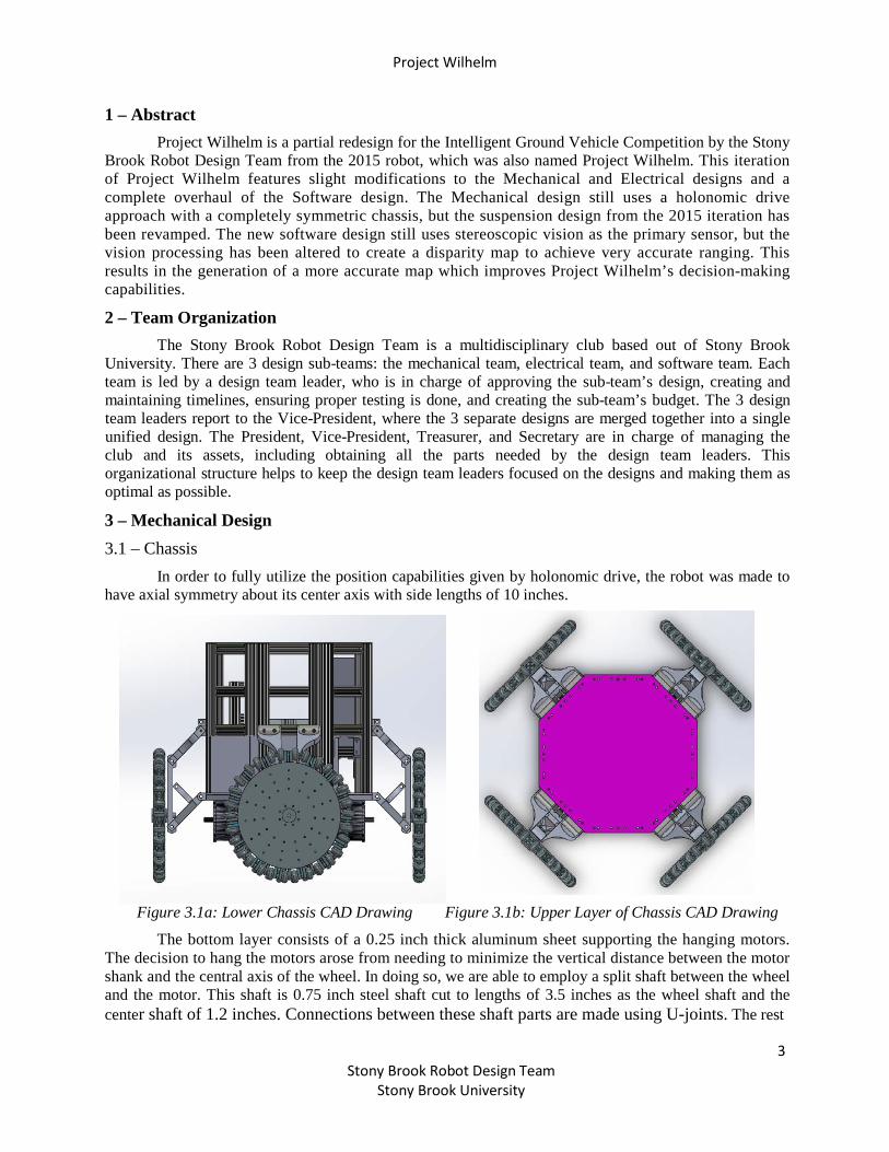
In order to fully utilize the position capabilities given by holonomic drive, the robot was made to have axial symmetry about its center axis with side lengths of 10 inches.
Figure 3.1a: Lower Chassis CAD Drawing Figure 3.1b: Upper Layer of Chassis CAD Drawing
The bottom layer consists of a 0.25 inch thick aluminum sheet supporting the hanging motors. The decision to hang the motors arose from needing to minimize the vertical distance between the motor shank and the central axis of the wheel. In doing so, we are able to employ a split shaft between the wheel and the motor. This shaft is 0.75 inch steel shaft cut to lengths of 3.5 inches as the wheel shaft and the center shaft of 1.2 inches. Connections between these shaft parts are made using U-joints. The rest
Project Wilhelm
4 Stony Brook Robot Design Team
Stony Brook University
of the robot frame is held to the bottom plate using 5/16" bolts, thus replacing the pemstuds and allowing the robot to be taken apart without the disassembly of the entire lower layer. The rest of the layers are held in place using right angle brackets compatible with 1.5 inch 8020 aluminum extrusion.
The robot consists of two more layers after this one: the first being a "power distribution" layer. This contains the robot's two batteries as well as the breaker box. The breaker box is inset into the exterior wall of the robot and interrupts the axial-symmetric pattern while maintaining the same major exterior dimension of the chassis. The panel is mounted on a hinge so that it may be unhooked from its position and be moved out of the way to perform maintenance on the batteries. The chassis layers above the battery layer are the computer and sensors layers. These are mounted to a half-inch sheet of polycarbonate plastic. To incorporate the 360 degree snag free camera rotation the slipring was mounted using a custom 3D printed mount. This houses the pan servo motor underneath the slipring. The servo is bolted to the main shaft that rotates the main sensor platform. This platform is a disk mounted to the main shaft with the cameras mounted radially away from the shaft. The two cameras are housed in a 3D printed housing which keeps the two cameras spaced 75 millimeters apart. The payload will be mounted on top of the base layer in a box that is just oversized for the load. The decision to bring the payload down lower than on last year's machine was to bring the center of gravity of the robot further down so as to prevent the robot from falling over. The more traction the drive gets the better it will perform, especially considering that the power output from the motors is not being directed into the direction of travel, but are components of the resultant vector necessary to achieve a desired motion.
3.2 – Suspension
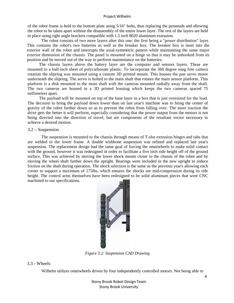
The suspension is mounted to the chassis through means of T-slot extrusion hinges and tabs that are welded to the lower frame. A double wishbone suspension was refined and replaced last year's suspension. The replacement design had the same goal of forcing the omniwheels to make solid contact with the ground, however it was redesigned in order to facilitate a five inch ride height off of the ground surface. This was achieved by moving the lower shock mount closer to the chassis of the robot and by moving the wheel shaft further down the upright. Bearings were included in the new upright to reduce friction on the shaft during operation. The shock selection is the same as the previous year's allowing each corner to support a maximum of 175lbs, which ensures the shocks are mid-compression during its ride height. The control arms themselves have been redesigned to be solid aluminum pieces that were CNC machined to our specifications.
Figure 3.2: Suspension CAD Drawing 3.3 - Wheels
Wilhelm utilizes omniwheels driven by four independently controlled motors. Not being able to
Project Wilhelm
5 Stony Brook Robot Design Team
Stony Brook University
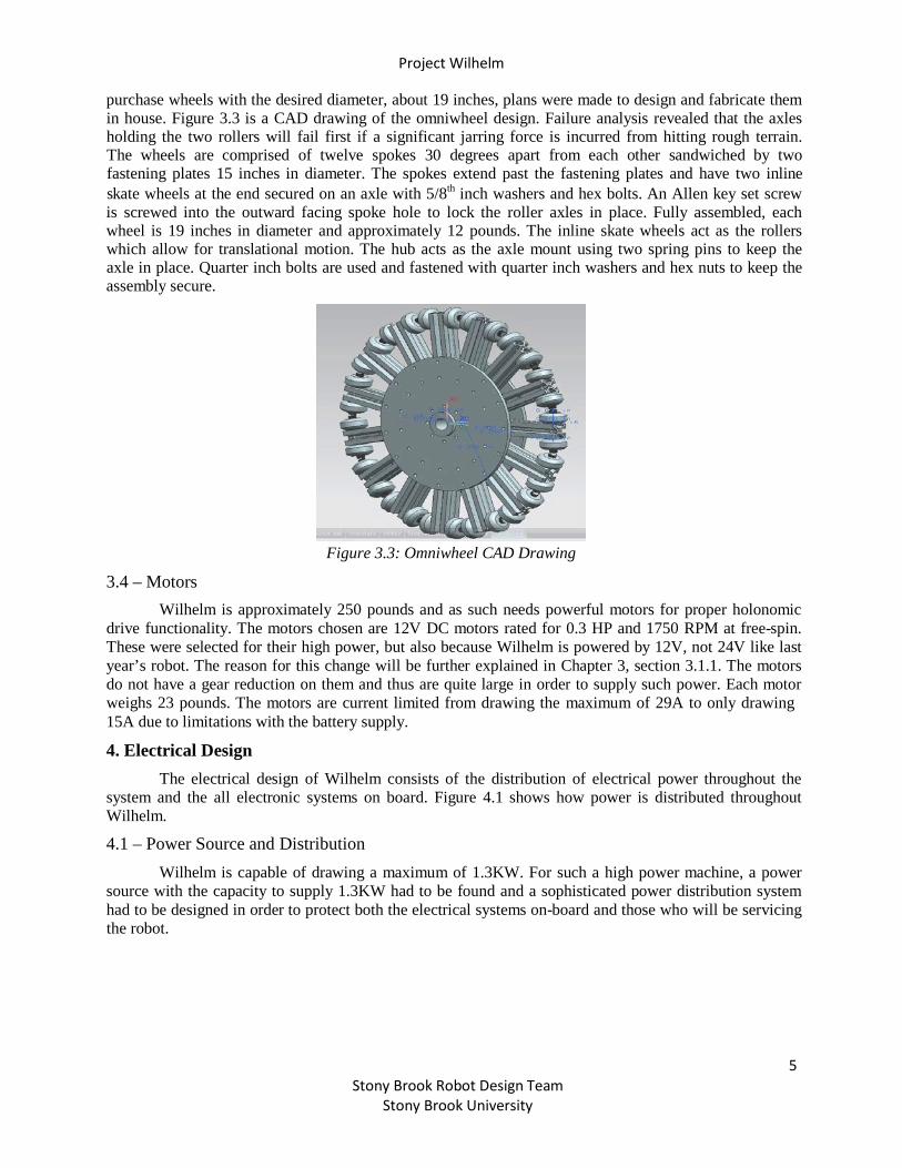
purchase wheels with the desired diameter, about 19 inches, plans were made to design and fabricate them in house. Figure 3.3 is a CAD drawing of the omniwheel design. Failure analysis revealed that the axles holding the two rollers will fail first if a significant jarring force is incurred from hitting rough terrain. The wheels are comprised of twelve spokes 30 degrees apart from each other sandwiched by two fastening plates 15 inches in diameter. The spokes extend past the fastening plates and have two inline skate wheels at the end secured on an axle with 5/8th inch washers and hex bolts. An Allen key set screw is screwed into the outward facing spoke hole to lock the roller axles in place. Fully assembled, each wheel is 19 inches in diameter and approximately 12 pounds. The inline skate wheels act as the rollers which allow for translational motion. The hub acts as the axle mount using two spring pins to keep the axle in place. Quarter inch bolts are used and fastened with quarter inch washers and hex nuts to keep the assembly secure.
3.4 – Motors
Figure 3.3: Omniwheel CAD Drawing
Wilhelm is approximately 250 pounds and as such needs powerful motors for proper holonomic drive functionality. The motors chosen are 12V DC motors rated for 0.3 HP and 1750 RPM at free-spin. These were selected for their high power, but also because Wilhelm is powered by 12V, not 24V like last year’s robot. The reason for this change will be further explained in Chapter 3, section 3.1.1. The motors do not have a gear reduction on them and thus are quite large in order to supply such power. Each motor weighs 23 pounds. The motors are current limited from drawing the maximum of 29A to only drawing 15A due to limitations with the battery supply.
4. Electrical Design
The electrical design of Wilhelm consists of the distribution of electrical power throughout the system and the all electronic systems on board. Figure 4.1 shows how power is distributed throughout Wilhelm.
4.1 – Power Source and Distribution
Wilhelm is capable of drawing a maximum of 1.3KW. For such a high power machine, a power source with the capacity to supply 1.3KW had to be found and a sophisticated power distribution system had to be designed in order to protect both the electrical systems on-board and those who will be servicing the robot.

Project Wilhelm
6 Stony Brook Robot Design Team
Stony Brook University
4.1.1 – Batteries
Figure 4.1: Distribution of Power in Wilhelm
Wilhelm is powered using two 12V marine batteries. Battery 1, which from this point shall be referred to as the electronics battery, has a 34Ah capacity at 20 hours. This battery is dedicated to running the logical electronics on-board Wilhelm. Battery 2, which from this point shall be referred to as the motor battery, has a 67Ah capacity at 20 hours. This battery is dedicated to running the motor controllers and all 4 motors. The separation between the electronics battery and the motor battery was made in order to prevent current spikes caused by the motors to adversely affect the logical electronics. Large instantaneous draws on the batteries by the motors can cause temporary voltage drops across the batteries. This creates voltage drops for the lower current drawing logical systems which in turn can cause undesirable results. Thus, the decision to separate the batteries into two distinct purposes was made so that a voltage drop across the motor battery will not affect the electronics battery. Both batteries do share a common ground though in order to maintain proper communication between the logic systems and the motor controllers.
Marine batteries were chosen for the electronics and motor batteries due to the ability of marine batteries to supply a moderately high current continuously as well as drop to near dead with minimal to no damage to the battery. These are very useful traits for marine applications where a sea-faring vessel might spend days at sea draining the batteries relentlessly. Wilhelm does not need to last on a single charge for very long, but it does need to be able to draw large currents continuously without the risk of potential damage. The model batteries chosen use lead-acid AGM technology, which supports a stabilized voltage even as the battery nears the end of its charge. Li-Ion batteries also have this feature, but the cost involved with purchasing Li-Ion batteries that would be capable of sourcing the currents necessary for proper operation and the L i - Ion charger to charge those batteries would have been far outside our budget. As such, the marine batteries were the best compromise of charge capacity, voltage stability, and cost. The major drawback is the weight which had to be accounted for in the mechanical design.
4.1.2 – Power Distribution
Each battery feeds independently into a distribution panel. The distribution panel is used to isolate the individual systems from each other. This is necessary in isolating potential problems in a specific circuit, such as a short circuit. The head of each branch at the distribution panel has a circuit breaker rated for the specific capacity of each system. This means that the computer system, which can draw up to 300W, has a much larger breaker than the E-Stop system, which can only draw up to 60W.
Project Wilhelm
7 Stony Brook Robot Design Team
Stony Brook University
The presence of the breakers is two-fold. The primary reason is for protection in case something goes wrong in a particular system, both for the system with the problem and all the other systems that could be affected by a surge. The second reason is for ease of powering on/off each system.
In addition to the circuit breakers for each individual system, a master breaker is capable of shutting down the entire robot at once. The master breaker is lies between the electronics battery and all the logical electrical systems. Despite not being electrically connected to the motor controllers, the master breaker has the ability to shut down the motor controllers as well because the E- Stop system discussed in chapter 4, section 4.2.3 disables power to the motor controllers via the Kilovac Contactor.
4.1.3 – Charging System
Wilhelm has a protected charging port on-board in order to charge the batteries without having to remove them. This is important as the process of moving batteries introduces risks of damage to batteries due to accidental shorting. By implementing a charging system, the risks are eliminated and the robot has a more finished and professional look. The charging port does connect directly to the battery terminals electrically. This presents a risk of accidental short via the charging port. To mediate this risk, a charging port enable switch has been added which disconnects the charging port from the battery terminals when the port is disabled. In addition, in-line fuses have been added between the enable switch and the battery terminals to prevent current surges through the charging port.
4.2 – Systems
Most of the components within each system are retail products which were chosen for their power efficiency and the quantity and quality of their features. There are a few custom designed components. These components were designed with efficiency in mind, but with safety as top priority.
4.2.1 – Motor System
The motor system is the only system that operates off of the motor battery. It has a dedicated circuit breaker at the distribution panel. After the breaker, the power passes through a Kilovac Contactor which has the capacity to switch up to 200A. The Kilovac contactor is the control mechanism for the E- Stop to kill power to the motor controllers and ultimately the motors.
4.2.1.1 – RoboClaw 2x30
The motor controllers chosen for Wilhelm are the RoboClaw 2x30 motor controllers. There are two on-board as each supports driving two motors independently and there are four independently powered motors on Wilhelm. These were selected for their encoder support and ease of communication with the computer. The encoder support was a necessity because holonomic drive requires precision when driving the motors and the only way to achieve such precision is with a small feedback loop involving encoders.
4.2.1.2 – Watchdog Circuit
Although the RoboClaw 2x30 motor controllers have many features, one feature they lack is a built in watchdog. The watchdog allows the motor controller to shut down if communication from the computer ceases. This is of utmost importance because if the software crashes, Wilhelm must stop all motion for safety reasons. As such, a watchdog circuit was designed and placed in-line between the computer and the motor controllers. The circuit consists of two 555 timers in mono-stable configuration. This provides a count-down which has been configured for 500ms. This means that if the computer stops communicating to the motor controllers for more than 500ms, the watchdog will shut down the motor controllers.
Project Wilhelm
8 Stony Brook Robot Design Team
Stony Brook University
4.2.2 – Computer System
The computer system includes the navigation computer and the Pixel Qi display. The Pixel Qi display is a specialized display designed specifically for outdoor viewing. The display is a special form of LCD with a backlight that can be toggled on or off. When the backlight is on, the screen appears like any normal LCD screen. However, if in direct sunlight, the backlight can be switched off and the screen turns to grayscale but remains perfectly readable due to ambient light. This is very useful for debugging code while outside in the sun and since the display is part of Wilhelm, there is no need to carry around a screen to debug.
4.2.2.1 – Navigation Computer
The navigation computer is a requirement for any robotic venture. The computer on-board Wilhelm has a 3rd generation Intel i7 processor on a mini-ITX motherboard with 16GB of RAM. The motherboard was selected due to its small form-factor and its reduced power requirements. The i7 processor is a moderately high computational power processor for the navigation program while still maintaining less than a 65W TDP. In addition, a low-power version of the Nvidia GeForce GT 730 graphics card was added in order to utilize the GPU for intensive graphical computation due to the stereoscopic vision which will be described further in chapter 4, section 4.2.4.1. A solid state drive (SSD) is used as the boot drive. This was done because a mobile platform such as a robot cannot have a spinning hard drive (HDD) running and expect reliability. The power supply unit (PSU) of the computer is an M4- ATX. The M4-ATX is a specialized 300W DC-DC PSU for low power computers. It will take as input 12V DC and convert down to all the necessary voltages for the proper operation of the computer.
4.2.3 – Emergency Stop System
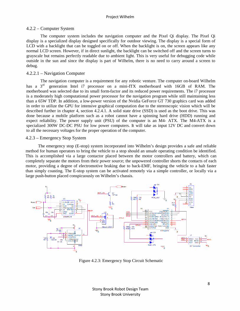
The emergency stop (E-stop) system incorporated into Wilhelm’s design provides a safe and reliable method for human operators to bring the vehicle to a stop should an unsafe operating condition be identified. This is accomplished via a large contactor placed between the motor controllers and battery, which can completely separate the motors from their power source; the unpowered controller shorts the contacts of each motor, providing a degree of electromotive braking due to back-EMF, bringing the vehicle to a halt faster than simply coasting. The E-stop system can be activated remotely via a simple controller, or locally via a large push-button placed conspicuously on Wilhelm’s chassis.
Figure 4.2.3: Emergency Stop Circuit Schematic
Project Wilhelm
9 Stony Brook Robot Design Team
Stony Brook University
4.2.3.1 – Local Kill-Switch
The heart of the push-button kill-switch located on Wilhelm’s chassis is a simple SN54HC74, which contains a pair of positive edge-triggered D flip-flops. The button used to activate the system is a SPDT momentary switch, which normally connects the active-low reset of the flip-flop to ground, but will set the flip-flop once the button is pressed. The output of this first flip-flop is connected to the clock input of the second, with each button press generating a single clock pulse. The second flip-flop has its data input connected to its inverted output, with the effect being that each button press causes the output of the second flip-flop to toggle. This signal is connected to a relay, which together with the output from the wireless portion, controls the current to the contactor. A monostable 555-timer circuit generates a reset pulse at power up to ensure the system always starts in a known state, and a pair of pull-up resistors and debouncing capacitors ensure reliable operation of the button.
4.2.3.2 – Remote Kill-Switch
Remote control of the emergency stop system is accomplished using a pair of ATtiny-2313 microcontrollers and Xbee Series 2 RF modules. The modules are pre-configured to communicate directly and only with each other (point-to-point), in such a way that after a brief communication test their operation is transparent to the microcontroller, and all data sent out via the UART interface of one is received unmodified by the other. A hardware timer on the transmitter triggers an interrupt to send the current status (enabled or disabled) to the E-stop where a UART receive interrupt parses the data and immediately updates the output to the relay controlling the contactor. The transmitter is configured to send data at a rate of 3 Hz, or to immediately send data when the current status is changed via a pair of pin-change interrupts associated with two push-buttons, one for each state. A watchdog timer on the E-stop ensures that if a signal loss or other interruption lasting longer than 2 seconds occurs, the motors are automatically disabled. Both the E-stop and the controller contain a pair of RG bicolor LEDs, which display the current status of the system.
4.2.4 – Peripherals System
The peripherals system circuit consists of three powered USB hubs that provide the power to all the sensors on-board Wilhelm and provides the connection between the peripheral devices and the navigation computer. This was done for system isolation as it is not necessary that the peripheral devices be powered whenever any work on the navigation computer is being done.
4.2.4.1 – Cameras
Wilhelm features two on-board Microsoft LifeCam Studio cameras. This provides stereoscopic vision for the navigation program. They are mounted on a Pan-Tilt system that has the capability to pan freely and tilt ±30°. This was implemented so that the navigation program can control the direction the cameras are facing independently of the direction the robot is moving which is useful for looking ahead or calculating the best path around an obstacle. This also allows Wilhelm to move freely in any direction without ever rotating thanks to holonomic drive and the dynamic cameras.
4.2.4.2 – Pan-Tilt
The Pan-Tilt system was developed using one Robotis MX-106T servo and one Robotis AX-12A servo. The MX-106T controls the panning and the AX-12A controls the tilting of the cameras. Thanks to the panning of the cameras, a slip-ring was used to ensure that the cameras can pan continuously in one direction without the wiring causing a problem.
4.2.4.3 – GPS
The Adafruit Ultimate Breakout GPS is onboard Wilhelm in order to obtain its positioning data. The GPS onboard has approximately 145 dBm of acquisition sensitivity and is able to communicate across 66 channels with a maximum error of 3 meters, supplying Wilhelm with impressively accurate
Project Wilhelm
10 Stony Brook Robot Design Team
Stony Brook University
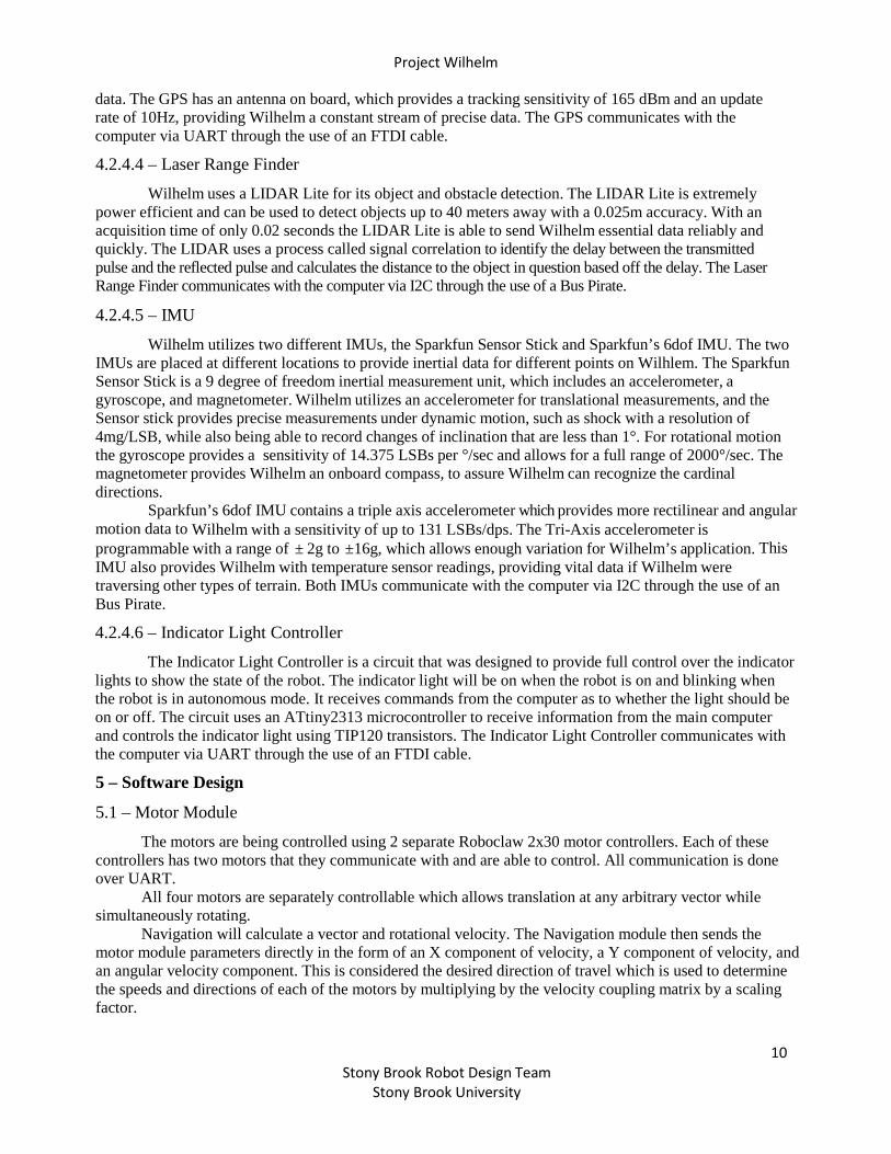
data. The GPS has an antenna on board, which provides a tracking sensitivity of 165 dBm and an update rate of 10Hz, providing Wilhelm a constant stream of precise data. The GPS communicates with the computer via UART through the use of an FTDI cable.
4.2.4.4 – Laser Range Finder
Wilhelm uses a LIDAR Lite for its object and obstacle detection. The LIDAR Lite is extremely power efficient and can be used to detect objects up to 40 meters away with a 0.025m accuracy. With an acquisition time of only 0.02 seconds the LIDAR Lite is able to send Wilhelm essential data reliably and quickly. The LIDAR uses a process called signal correlation to identify the delay between the transmitted pulse and the reflected pulse and calculates the distance to the object in question based off the delay. The Laser Range Finder communicates with the computer via I2C through the use of a Bus Pirate.
4.2.4.5 – IMU
Wilhelm utilizes two different IMUs, the Sparkfun Sensor Stick and Sparkfun’s 6dof IMU. The two IMUs are placed at different locations to provide inertial data for different points on Wilhlem. The Sparkfun Sensor Stick is a 9 degree of freedom inertial measurement unit, which includes an accelerometer, a gyroscope, and magnetometer. Wilhelm utilizes an accelerometer for translational measurements, and the Sensor stick provides precise measurements under dynamic motion, such as shock with a resolution of 4mg/LSB, while also being able to record changes of inclination that are less than 1°. For rotational motion the gyroscope provides a sensitivity of 14.375 LSBs per °/sec and allows for a full range of 2000°/sec. The magnetometer provides Wilhelm an onboard compass, to assure Wilhelm can recognize the cardinal directions.
Sparkfun’s 6dof IMU contains a triple axis accelerometer which provides more rectilinear and angular motion data to Wilhelm with a sensitivity of up to 131 LSBs/dps. The Tri-Axis accelerometer is programmable with a range of ± 2g to ±16g, which allows enough variation for Wilhelm’s application. This IMU also provides Wilhelm with temperature sensor readings, providing vital data if Wilhelm were traversing other types of terrain. Both IMUs communicate with the computer via I2C through the use of an Bus Pirate.
4.2.4.6 – Indicator Light Controller
The Indicator Light Controller is a circuit that was designed to provide full control over the indicator lights to show the state of the robot. The indicator light will be on when the robot is on and blinking when the robot is in autonomous mode. It receives commands from the computer as to whether the light should be on or off. The circuit uses an ATtiny2313 microcontroller to receive information from the main computer and controls the indicator light using TIP120 transistors. The Indicator Light Controller communicates with the computer via UART through the use of an FTDI cable.
5 – Software Design
5.1 – Motor Module
The motors are being controlled using 2 separate Roboclaw 2x30 motor controllers. Each of these controllers has two motors that they communicate with and are able to control. All communication is done over UART.
All four motors are separately controllable which allows translation at any arbitrary vector while simultaneously rotating.
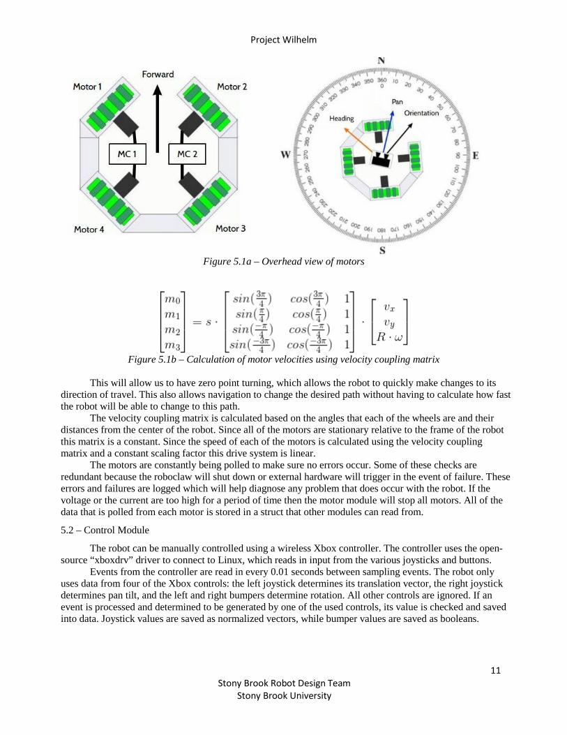
Navigation will calculate a vector and rotational velocity. The Navigation module then sends the motor module parameters directly in the form of an X component of velocity, a Y component of velocity, and an angular velocity component. This is considered the desired direction of travel which is used to determine the speeds and directions of each of the motors by multiplying by the velocity coupling matrix by a scaling factor.
Project Wilhelm
11 Stony Brook Robot Design Team
Stony Brook University
Figure 5.1a – Overhead view of motors
Figure 5.1b – Calculation of motor velocities using velocity coupling matrix
This will allow us to have zero point turning, which allows the robot to quickly make changes to its
direction of travel. This also allows navigation to change the desired path without having to calculate how fast the robot will be able to change to this path.
The velocity coupling matrix is calculated based on the angles that each of the wheels are and their distances from the center of the robot. Since all of the motors are stationary relative to the frame of the robot this matrix is a constant. Since the speed of each of the motors is calculated using the velocity coupling matrix and a constant scaling factor this drive system is linear.
The motors are constantly being polled to make sure no errors occur. Some of these checks are redundant because the roboclaw will shut down or external hardware will trigger in the event of failure. These errors and failures are logged which will help diagnose any problem that does occur with the robot. If the voltage or the current are too high for a period of time then the motor module will stop all motors. All of the data that is polled from each motor is stored in a struct that other modules can read from.
5.2 – Control Module
The robot can be manually controlled using a wireless Xbox controller. The controller uses the open-source “xboxdrv” driver to connect to Linux, which reads in input from the various joysticks and buttons.
Events from the controller are read in every 0.01 seconds between sampling events. The robot only uses data from four of the Xbox controls: the left joystick determines its translation vector, the right joystick determines pan tilt, and the left and right bumpers determine rotation. All other controls are ignored. If an event is processed and determined to be generated by one of the used controls, its value is checked and saved into data. Joystick values are saved as normalized vectors, while bumper values are saved as booleans.

Project Wilhelm
12 Stony Brook Robot Design Team
Stony Brook University
5.3 – Vision Module
5.3.1 – Stereo Rig
The robot’s primary sensory input comes from two cameras arranged as a stereo pair. Once properly calibrated, these cameras provide per-pixel depth information via a stereo disparity map. This disparity map can be used to extract range data from obstacles which are in visual range. The cameras used are two Microsoft LifeCam Studio webcams, fixed in a 3D printed stereo mount which has a baseline of 75 millimeters.
5.3.2 – Image Processor
5.3.2.1 – Stereo Disparity Map
The two cameras are first calibrated manually using a checkerboard pattern of known geometry. The calibration procedure is used to extract the intrinsic camera parameters (focal length, origin coordinates), the extrinsic stereo parameters (translation, rotation between camera origins), as well as the distortion parameters specific to each device. Once known, the frames can be rectified and re-mapped such that stereo algorithms can quickly and efficiently determine correspondence between pixels in the left and right frames. Proper calibration and rectification are critical procedures upon which stereo disparity calculation heavily relies - small errors can make large differences in the quality of the disparity output. Frames are captured from the cameras at 20 FPS. Upon each capture, the images are rectified using the mapping determined during the calibration. The rectified left and right frames are then used to compute the disparity map for pixels in the left frame. The implementation utilizes a Block Matching algorithm to find correspondences along scan lines for optimal performance (blocks are 15 pixels square with a maximum disparity of 64 pixels). This procedure produces a disparity map D(u,v) where each pixel value represents the distance in pixels of the corresponding points between the left and right images. In other words, for a point p located at (ul,v) in the left image and (ur,v) in the right image,D(u,v)=ul-ur.
Figure 5.3.2.1 – Epipolar Geometry of Stereoscopic Vision
5.3.2.2 – Grass Histogram Back-Projection
This method is used to find objects of interest, in this case, grass, in images received from the robot's cameras. For this purpose the algorithm takes the colored histogram of an image containing only grass (Fig 5.3.2.2.A. Inside delimited area), because gray-scale images do not offer enough distinguishable features to differ the grass over something else, such as obstacles and fences.

Project Wilhelm
13 Stony Brook Robot Design Team
Stony Brook University
With the grass histogram we are able to back-project it over the frames taken from the cameras and get
the probability of each image pixel being grass (Fig. 5.3.2.2.B.). We then set a reasonable threshold to get a binary mask (Fig. 5.3.2.2.C.) of the resulting image, with white corresponding to grass and black as not grass. It's important to note that this method also differentiates grass over lanes even though lanes are still grass, but in different color. This is used to distinguish the drivable ground from the non-drivable ground. (Fig 5.3.2.2.D.)
Figure 5.3.2.2 – Sample of Histogram BackProjection application
5.4 – Localization Module
5.4.1 – GPS
The GPS is used to localize the robot relative to the desired GPS waypoint. The GPS unit sends industry-standard NMEA sentences over UART and the latitude, longitude, ground speed, and heading are extracted from the received sentences. The GPS unit updates at 10Hz, which is the maximum update rate the unit can handle. The extracted information is entered into a struct so other modules may use the information as necessary.
5.4.2 – IMU The robot utilizes an Inertial Measurement Unit (IMU) to track the inertial properties of the stereo rig.
An accelerometer (ADXL345), a magnetometer (HMC5883L), and a gyroscope (ITG-3200) are combined onto a single chip and fixed to the back of the stereo cameras. Together, these devices provide data related to the inertial pose of the visual origin. The accelerometer measures the instantaneous accelerations in the x, y and z-axes, while the gyroscope determines the rotational pose of the cameras with respect to the vector of gravitational acceleration. The IMU also includes the magnetometer, which is used to establish heading and prevent drift. The navigation algorithm used by the robot synthesizes the data from these devices, along with the cameras and GPS, to produce a motion command aimed at directing the robot towards its target.
The advantage of including an IMU is that it provides a direct measurement of the inertial state of the robot. This information provides critical feedback for the navigation algorithm, which relies on constant updates for its heading and speed data, since the omni-wheeled holonomic drive system introduces high process noise when executing a drive command. In addition, acceleration measurements can be used to stabilize shaky video feed. Ultimately, these devices provide vital data which contributes to the overall robustness of the navigation algorithm.
The disadvantage of using the IMU is that it’s feedback is often very noisy and inaccurate. This

Project Wilhelm
14 Stony Brook Robot Design Team
Stony Brook University
introduces additional uncertainty into the system, despite its primary role as a feedback mechanism. The nature of acceleration and orientation is that it changes rapidly and unpredictably, especially for a robot which does not ride smoothly on the terrain. This is reflected in the data acquired by the devices, and little can be done to help the inaccuracies.
6 – Cost
Sub-Team Item Cost
Mechanical
Chassis $2,500 Suspension $4,000 Wheels $1,600 Motors $1,250
Electrical
Batteries $500 Power Distribution $200 Motor Controllers $650 Computer $1250 E-Stop $250 Sensors $1,000
Total $13,200