wide-band circularly polarized cavity backed crossed ... saurav(1), debdeep sarkar(1), and kumar...
TRANSCRIPT

32nd URSI GASS, Montreal, 19–26 August 2017
Wide-band Circularly Polarized Cavity Backed Crossed Dipole Antenna
Kushmanda Saurav(1), Debdeep sarkar(1), and Kumar Vaibhav Srivastava(1)
(1) Department of Electrical Engineering Indian Institute of Technology, Kanpur, Kanpur-208016, Uttar Pradesh, India
Abstract
In this paper, a wide-band circularly polarized (CP) crosseddipole antenna is proposed. The CP crossed dipole an-tenna is backed by a cavity reflector to achieve wide-bandCP radiation with enhanced gain and uni-directional pat-tern accompanied by high front to back lobe ratio. A com-prehensive study on the effect of the vertical walls of thecavity reflector on the CP radiation performance has beenperformed. It is analyzed that the cavity reflector providesan additional CP mode which is merged with the referenceCP mode of crossed dipole to get a bandwidth enhance-ment in the CP operation. The concentration of electricfield vectors on the inner walls of cavity provides an en-hanced and stable gain of a CP crossed dipole across the en-tire CP operating bandwidth as compared to a PEC reflectorbacked crossed dipole antenna. The concept of wide-band,uni-directional and high gain CP crossed dipole antenna isvalidated by measurement carried out on the fabricated an-tenna prototype. Measured results confirm that the cavitybacked crossed dipole exhibits a CP operating bandwidthof 22.89% (2.52−3.17 GHz), an average gain of 8 dBic anduni-directional radiation pattern with a front to back loberatio > 25 dB.
1 Introduction
The crossed dipole antenna is one of the suitable candi-date for generation of circularly polarized (CP) radiation[1]. The CP crossed dipole antenna consists of two half-wavelength dipoles placed orthogonally and fed with cur-rents of equal amplitude which are in phase quadrature. TheCP crossed dipole antenna exhibits a bi-directional radia-tion pattern with low gain. However, many wireless appli-cations require antennas with uni-directional radiation withhigh front to back lobe ratio. So, the crossed dipoles areequipped with a reflector to get the desired uni-directionalCP radiation. Classically, the crossed dipoles are usedwith PEC reflectors to get uni-directional radiation. Sev-eral studies have been performed to get an enhancementin CP operating bandwidth of a CP crossed dipole antenna[2]−[3]. The use of PEC reflector in conjunction with awide-band CP crossed dipole antenna does not lead to anenhanced and stable gain over the entire CP operating band.For the PEC reflector backed wide-band CP crossed dipole,gain drops significantly when the reflector height ≈ λ . Re-cently, the use of cavity as a reflector with the crossed
Figure 1. Schematic of the proposed cavity reflectorbacked CP crossed dipole antenna. Ld = 44 mm, wd = 2mm, ri = 3 mm, wr = 0.3 mm, Cb = 100 mm and h0 = 30mm.
dipole to get an enhanced CP radiation performance hasgained popularity [4]−[8]. The enhancement of 3-dB ax-ial ratio beamwidth of CP crossed dipole antenna has beenachieved by means of cavity backing [4]−[5]. The increasein CP operating bandwidth in CP crossed dipole with theuse of cavity reflector has been studied in [6]−[8].
In this work, a wide-band CP cavity backed crossed dipoleantenna design is presented. The cavity backing excites aCP mode in addition to the reference CP mode of crosseddipole antenna. The judicious choice of the cavity cross-section dimension can enable the merging of the CP cavitymode with the original CP mode of crossed dipole, lead-ing to an enhancement in CP operating bandwidth. Thevertical walls of the cavity reflector concentrate the electricfield vectors within them and are capable of providing a sta-ble and enhanced gain in the CP operating band. The pro-posed concept of wide-band, high-gain and uni-directionalCP cavity backed crossed dipole antenna has been validatedby means of measurements conducted on fabricated proto-type of antenna.
2 Circularly Polarized Crossed Dipole An-tenna Backed by a Cavity Reflector
CP crossed dipole antenna consisting of a set of orthogo-nally oriented dipoles connected through a one quarter va-
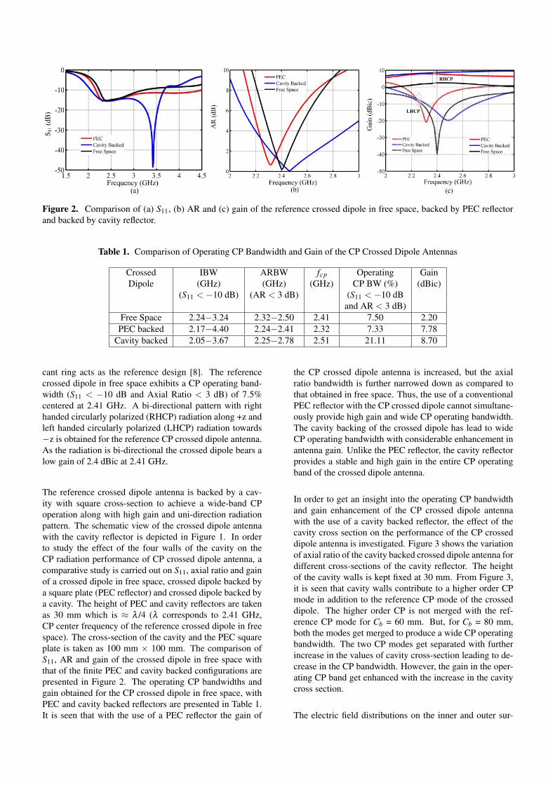
Figure 2. Comparison of (a) S11, (b) AR and (c) gain of the reference crossed dipole in free space, backed by PEC reflectorand backed by cavity reflector.
Table 1. Comparison of Operating CP Bandwidth and Gain of the CP Crossed Dipole Antennas
Crossed IBW ARBW fcp Operating GainDipole (GHz) (GHz) (GHz) CP BW (%) (dBic)
(S11 < −10 dB) (AR < 3 dB) (S11 < −10 dBand AR < 3 dB)
Free Space 2.24−3.24 2.32−2.50 2.41 7.50 2.20PEC backed 2.17−4.40 2.24−2.41 2.32 7.33 7.78
Cavity backed 2.05−3.67 2.25−2.78 2.51 21.11 8.70
cant ring acts as the reference design [8]. The referencecrossed dipole in free space exhibits a CP operating band-width (S11 < −10 dB and Axial Ratio < 3 dB) of 7.5%centered at 2.41 GHz. A bi-directional pattern with righthanded circularly polarized (RHCP) radiation along +z andleft handed circularly polarized (LHCP) radiation towards−z is obtained for the reference CP crossed dipole antenna.As the radiation is bi-directional the crossed dipole bears alow gain of 2.4 dBic at 2.41 GHz.
The reference crossed dipole antenna is backed by a cav-ity with square cross-section to achieve a wide-band CPoperation along with high gain and uni-direction radiationpattern. The schematic view of the crossed dipole antennawith the cavity reflector is depicted in Figure 1. In orderto study the effect of the four walls of the cavity on theCP radiation performance of CP crossed dipole antenna, acomparative study is carried out on S11, axial ratio and gainof a crossed dipole in free space, crossed dipole backed bya square plate (PEC reflector) and crossed dipole backed bya cavity. The height of PEC and cavity reflectors are takenas 30 mm which is ≈ λ /4 (λ corresponds to 2.41 GHz,CP center frequency of the reference crossed dipole in freespace). The cross-section of the cavity and the PEC squareplate is taken as 100 mm × 100 mm. The comparison ofS11, AR and gain of the crossed dipole in free space withthat of the finite PEC and cavity backed configurations arepresented in Figure 2. The operating CP bandwidths andgain obtained for the CP crossed dipole in free space, withPEC and cavity backed reflectors are presented in Table 1.It is seen that with the use of a PEC reflector the gain of
the CP crossed dipole antenna is increased, but the axialratio bandwidth is further narrowed down as compared tothat obtained in free space. Thus, the use of a conventionalPEC reflector with the CP crossed dipole cannot simultane-ously provide high gain and wide CP operating bandwidth.The cavity backing of the crossed dipole has lead to wideCP operating bandwidth with considerable enhancement inantenna gain. Unlike the PEC reflector, the cavity reflectorprovides a stable and high gain in the entire CP operatingband of the crossed dipole antenna.
In order to get an insight into the operating CP bandwidthand gain enhancement of the CP crossed dipole antennawith the use of a cavity backed reflector, the effect of thecavity cross section on the performance of the CP crosseddipole antenna is investigated. Figure 3 shows the variationof axial ratio of the cavity backed crossed dipole antenna fordifferent cross-sections of the cavity reflector. The heightof the cavity walls is kept fixed at 30 mm. From Figure 3,it is seen that cavity walls contribute to a higher order CPmode in addition to the reference CP mode of the crosseddipole. The higher order CP is not merged with the ref-erence CP mode for Cb = 60 mm. But, for Cb = 80 mm,both the modes get merged to produce a wide CP operatingbandwidth. The two CP modes get separated with furtherincrease in the values of cavity cross-section leading to de-crease in the CP bandwidth. However, the gain in the oper-ating CP band get enhanced with the increase in the cavitycross section.
The electric field distributions on the inner and outer sur-

Figure 3. Variation of axial ratio for the different crosssections of the cavity reflector (ho is kept equal to 30 mmin all cases) for the proposed cavity reflector backed CPcrossed dipole antenna.
Figure 4. Electric-field distributions on the (a) inner wallsand (b) outer walls of the cavity backed reflector at CP cen-tre frequency (2.51 GHz) for the proposed cavity reflectorbacked CP crossed dipole antenna.
Figure 5. Photograph of the fabricated cavity reflectorbacked CP crossed dipole antenna.
Figure 6. Comparison of simulated and measured (a) S11,(b) axial ratio and gain for the proposed cavity reflectorbacked CP crossed dipole antenna.
face of the cavity walls at CP centre frequency for differenttime instants are depicted in Figure 4. The concentration ofthe electric field vectors on the surface of inner walls is verylarge as compared to that observed on the outer surface. Theconcentration of the electric field vectors on cavity surface,leads to the enhanced and stable gain in the operating CPbandwidth of the cavity backed crossed dipole antenna. Thecounterclockwise rotation of electric field vectors on the in-ner and outer walls of cavity leads to a RHCP radiation inthe broadside direction.
3 Measured Results
In order to validate the concept of high gain, large frontto back lobe ratio and wide CP operating bandwidth of thecavity backed crossed dipole antenna, a prototype of thecrossed dipole antenna with cavity reflector of dimension100 mm × 100 mm × 30 mm has been fabricated. A broad-band microstrip to broadside coupled strip line transition isused to provide a practical feeding to the crossed dipole an-tenna [8]. The photograph of the fabricated prototype ofthe cavity reflector backed CP crossed dipole is depicted inFigure 5.
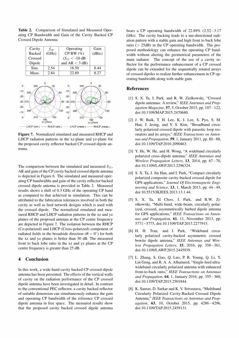
Table 2. Comparison of Simulated and Measured Oper-ating CP Bandwidth and Gain of the Cavity Backed CPCrossed Dipole Antenna
Cavity fcp Operating GainBacked (GHz) CP BW (%) (dBic)Crossed (S11 < -10 dBDipole and AR < 3 dB)Sim. 2.54 18.50 8.44
Meas. 2.84 22.89 8.27
Figure 7. Normalized simulated and measured RHCP andLHCP radiation patterns in the xz-plane and yz-plane forthe proposed cavity reflector backed CP crossed dipole an-tenna.
The comparison between the simulated and measured S11,AR and gain of the CP cavity backed crossed dipole antennais depicted in Figure 6. The simulated and measured oper-ating CP bandwidths and gain of the cavity reflector backedcrossed dipole antenna is provided in Table 2. Measuredresults shows a shift of 0.3 GHz of the operating CP bandas compared to that achieved in simulation. This can beattributed to the fabrication tolerances involved in both thecavity as well as feed network designs which is used withthe crossed dipole. The normalized simulated and mea-sured RHCP and LHCP radiation patterns in the xz and yzplanes of the proposed antenna at the CP centre frequencyare depicted in Figure 7. The isolation between the RHCP(Co-polarized) and LHCP (Cross-polarized) component ofradiated fields in the broadside direction (θ = 0◦) for boththe xz and yz planes is better than 30 dB. The measuredfront to back lobe ratio in the xz and yz planes at the CPcentre frequency is greater than 25 dB.
4 Conclusion
In this work, a wide-band cavity backed CP crossed dipoleantenna has been presented. The effects of the vertical wallsof cavity on the radiation performance of the CP crosseddipole antenna have been investigated in detail. In contrastto the conventional PEC reflector, a cavity backed reflectorof suitable dimension can simultaneously enhance the gainand operating CP bandwidth of the reference CP crosseddipole antenna in free space. The measured results showthat the proposed cavity backed crossed dipole antenna
bears a CP operating bandwidth of 22.89% (2.52−3.17GHz). The cavity backing leads to a uni-directional radi-ation pattern with a stable gain and high front to back loberatio (> 25dB) in the CP operating bandwidth. The pro-posed methodology can enhance the operating CP band-width without altering the geometrical parameters of themain radiator. The concept of the use of a cavity re-flector for the performance enhancement of a CP crosseddipole can be extended for the sequentially rotated arraysof crossed dipoles to realize further enhancement in CP op-erating bandwidth along with stable gain.
References
[1] S. X. Ta, I. Park, and R. W. Ziolkowski, “Crosseddipole antennas: A review,” IEEE Antennas and Prop-agation Magazine, 57, 5, October 2015, pp. 107−122,doi:10.1109/MAP.2015.2470680.
[2] J. W. Baik, T. H. Lee, K. J. Lee, S. Pyo, S. M.Han, J. Jeong, and Y. S. Kim, “Broadband circu-larly polarized crossed dipole with parasitic loop res-onators and its arrays,” IEEE Transactions on Anten-nas and Propagation, 59, 1, January 2011, pp. 80−88,doi:10.1109/TAP.2010.2090463.
[3] Y. He, W. He, and H. Wong, “A wideband circularlypolarized cross-dipole antenna,” IEEE Antennas andWireless Propagation Letters, 13, 2014, pp. 67−70,doi:10.1109/LAWP.2013.2296324.
[4] S. X. Ta, J. Jin Han, and I. Park, “Compact circularlypolarized composite cavity-backed crossed dipole forGPS applications,” Journal Of Electromagnetic Engi-neering and Science, 13, 1, March 2013, pp. 44−49,doi:10.5515/JKIEES.2013.13.1.44.
[5] S. X. Ta, H Choo, I. Park, and R.W. Zi-olkowski, “Multi-band, wide-beam, circularly polar-ized, crossed, asymmetrically barbed dipole antennafor GPS applications,” IEEE Transactions on Anten-nas and Propagation, 61, 11, November 2013, pp.5771−5775, doi:10.1109/TAP.2013.2277915.
[6] H. H. Tran, and I. Park, “Wideband circu-larly polarized cavity-backed asymmetric crossedbowtie dipole antenna,” IEEE Antennas and Wire-less Propagation Letters, 15, 2016, pp. 358−361,doi:10.1109/LAWP.2015.2445939.
[7] L. Zhang, S. Gao, Q. Luo, P. R. Young, Q. Li, Y.Lin Geng, and R. A. A. Alhameed, “Single-feed ultra-wideband circularly polarized antenna with enhancedfront-to-back ratio,” IEEE Transactions on Antennasand Propagation, 64, 1, January 2016, pp. 355−360,doi:10.1109/TAP.2015.2501844.
[8] K. Saurav, D. Sarkar and K. V. Srivastava, “MultibandCircularly Polarized Cavity-Backed Crossed DipoleAntenna,” IEEE Transactions on Antennas and Prop-agation, 63, 10, October 2015, pp. 4286−4296,doi:10.1109/TAP.2015.2459131.