wi-sun phy measurement software is wi-sun phy measurement software? wi-sun phy measurement software...
TRANSCRIPT

Product Introduction
MX705010A
MS2690A/MS2691A/MS2692A/MS2830A Signal Analyzer
Wi-SUN PHY Measurement Software
Copyright© ANRITSU MX705010A-E-L-1
Slide 1
MX705010A
Wi-SUN PHY Measurement Software
Version 3.0
November 2014
Anritsu Corporation
Product Introduction

Copyright© ANRITSU MX705010A-E-L-1
Slide 2
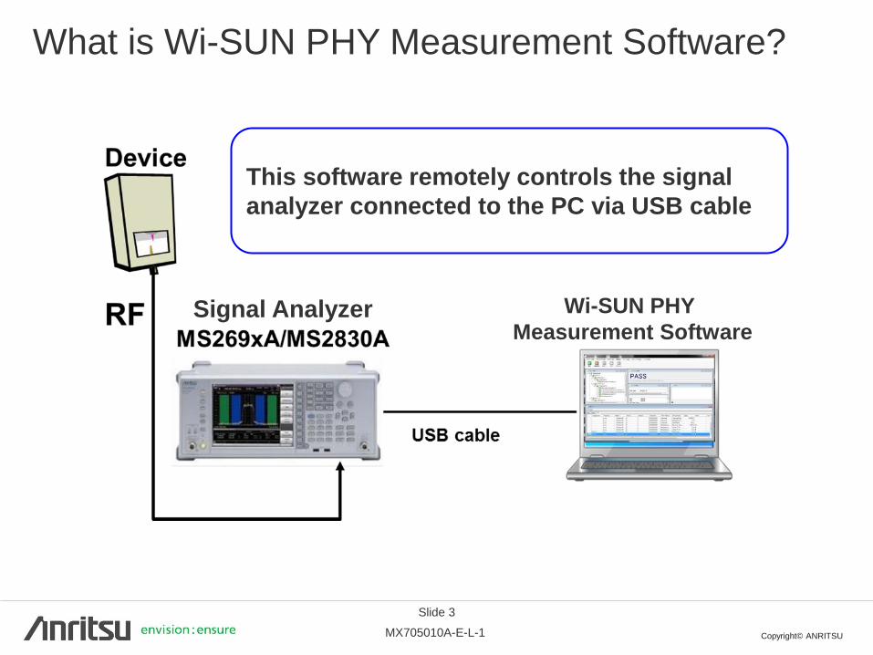
What is Wi-SUN PHY Measurement Software?
This PC software supports use of a signal analyzer for evaluating the PHY layer
(802.15.4g PHY) of Smart Utility Network wireless communications (Wi-SUN).
This software supports the following tests:
Wi-SUN PHY Transmitter Test
Wi-SUN PHY Receiver Test
TELEC-T245 Test
The following signal analyzers are supported:
MS2690A/MS2691A/MS2692A
MS2830A
The signal analyzer is controlled by remote commands from this PC
software to perform efficient RF tests of Wi-SUN devices, showing its
usefulness in improving R&D efficiency!
Copyright© ANRITSU MX705010A-E-L-1
本ソフトウェアはPCとシグナルアナライザをUSBケー
ブルにて接続することでリモートコントロールします
Slide 3
What is Wi-SUN PHY Measurement Software?
Wi-SUN PHY
Measurement Software
This software remotely controls the signal
analyzer connected to the PC via USB cable
Signal Analyzer

Copyright© ANRITSU MX705010A-E-L-1
Slide 4
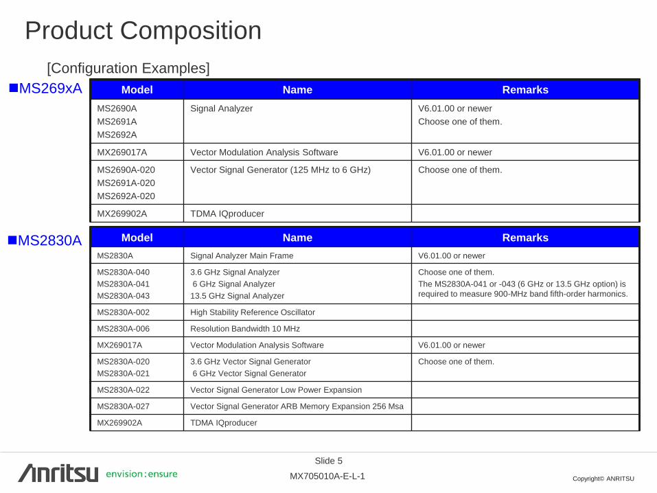
Product Composition
Model Name Explanation
MX705010A Wi-SUN PHY Measurement
Software
Performs measurements using remote control of
signal analyzer by remote commands
■MX705010A Wi-SUN PHY Measurement Software
■Measuring Instrument
One MS269xA or MS2830A can be used.
(Firmware V6.01.00 or newer)
[Recommended options]
MS2690A/MS2691A/MS2692A
MX269017A, MS269xA-020, MX269902A
MS2830A
MS2830A-002, MS2830A-006, MX269017A,
MS2830A-020 or -021, MS2830A-022, MS2830A-027, MX269902A
Copyright© ANRITSU MX705010A-E-L-1
Slide 5
Product Composition
Model Name Remarks
MS2690A
MS2691A
MS2692A
Signal Analyzer V6.01.00 or newer
Choose one of them.
MX269017A Vector Modulation Analysis Software V6.01.00 or newer
MS2690A-020
MS2691A-020
MS2692A-020
Vector Signal Generator (125 MHz to 6 GHz) Choose one of them.
MX269902A TDMA IQproducer
Model Name Remarks
MS2830A Signal Analyzer Main Frame V6.01.00 or newer
MS2830A-040
MS2830A-041
MS2830A-043
3.6 GHz Signal Analyzer
6 GHz Signal Analyzer
13.5 GHz Signal Analyzer
Choose one of them.
The MS2830A-041 or -043 (6 GHz or 13.5 GHz option) is
required to measure 900-MHz band fifth-order harmonics.
MS2830A-002 High Stability Reference Oscillator
MS2830A-006 Resolution Bandwidth 10 MHz
MX269017A Vector Modulation Analysis Software V6.01.00 or newer
MS2830A-020
MS2830A-021
3.6 GHz Vector Signal Generator
6 GHz Vector Signal Generator
Choose one of them.
MS2830A-022 Vector Signal Generator Low Power Expansion
MS2830A-027 Vector Signal Generator ARB Memory Expansion 256 Msa
MX269902A TDMA IQproducer
[Configuration Examples]
MS269xA
MS2830A

Copyright© ANRITSU MX705010A-E-L-1
Slide 6
Operating Environment/Related Standards
Item Explanation OS Windows® 7 Professional SP1 or newer
Memory 4 GB minimum
HDD Free Space 80 GB minimum
Display Resolution WXGA 1280 × 768 or more
USB I/F
USB 2.0
Requires PC with two USB ports for operation as host
For remote control of signal analyzer and insertion of license dongle
Use of other USB equipment requires PC with three USB ports
PC: A type, Signal Analyzer: B type
USB cables are not provided with this software.
Software Microsoft Excel 2010 or Microsoft Excel 2013
National Instruments
NI-488.2 NI-VISA V3.1.1 or newer must be installed.
■Operating Environment (MX705010A)
■Related Standards (MX705010A)
No. Explanation
1
Wi-SUN Alliance Test and Certification Working Group (TCWG)
IEEE 802.15.4g PHY Conformance Test Suite Specification
Revision 1V08
2
TELEC-T245 Version 4.0
Specified low-power radio equipment for telemeter, telecontrol or data transmission
(920 MHz band)

Copyright© ANRITSU MX705010A-E-L-1
Slide 7
Measurements: Wi-SUN PHY TX Test
Test No. Test Item Test Contents
1 Modulation Quality
The two modulation quality parameters specified in the FSK
modulation Eye diagram are measured to evaluate whether the
quality is within the standards or not. Whether the frequency
deviation error and zero crossing offset are within the permissible
range or not is specified.
2 Transmitter
Frequency Offset
The offset of the specified transmission frequency (channel center
frequency) is measured to evaluate whether it is within range or
not.
3
Transmitter Adjacent
Channel Power
Ratio
The leakage power at 4 points adjacent to the specified channel is
measured to evaluate whether it is within the specified range of not.
4 Test Vectors The sent frames are analyzed to evaluate whether they are in the
expected format or not.

Copyright© ANRITSU MX705010A-E-L-1
8
Measurement Items: Wi-SUN PHY RX Test
Test No. Test Item Test Contents
1 Receiver Sensitivity
Test
The RX sensitivity is tested and the results evaluated (PER
measurement).
The specified number of packets are output from the Vector Signal
Generator at the specified output level. After transmission is
completed, receipt of the packets by the Wi-SUN device is
confirmed and these results are input to this software.
2 Packet Test
The RX sensitivity is tested and the results evaluated (PER
measurement).
The frame size is 20 octets.
The specified number of packets are output from the Vector Signal
Generator at the specified output level. After transmission is
completed (specified number of frames), receipt of the packets by
the Wi-SUN device is confirmed and these results are input to this
software.
This software can also perform BER measurement to confirm RX performance. If the Wi-SUN device can output Data and
Clock signals, this software can perform BER measurement in linked operation with the signal analyzer with installer BER
measurement option* for BER evaluations. However, BER measurement is not specified in the Wi-SUN PHY tests. *MS2690A/MS2691A/MS2692A-020 Vector Signal Generator installed in MS2690A/MS2691A/MS2692A Signal Analyzer
*MS2830A-026 BER Measurement Function (option) installed in MS2830A Signal Analyzer
Adjacent/Alternate Channel Rejection Ratio is not supported. Moreover, at test execution, in addition to a signal analyzer
with a built-in signal generator, a signal generator for outputting the interference wave is also required.
Copyright© ANRITSU MX705010A-E-L-1
Slide 9
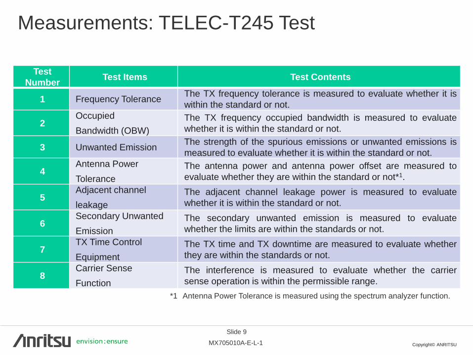
Measurements: TELEC-T245 Test
Test
Number Test Items Test Contents
1 Frequency Tolerance The TX frequency tolerance is measured to evaluate whether it is
within the standard or not.
2 Occupied
Bandwidth (OBW)
The TX frequency occupied bandwidth is measured to evaluate
whether it is within the standard or not.
3 Unwanted Emission The strength of the spurious emissions or unwanted emissions is
measured to evaluate whether it is within the standard or not.
4 Antenna Power
Tolerance
The antenna power and antenna power offset are measured to
evaluate whether they are within the standard or not*1.
5 Adjacent channel
leakage
The adjacent channel leakage power is measured to evaluate
whether it is within the standard or not.
6 Secondary Unwanted
Emission
The secondary unwanted emission is measured to evaluate
whether the limits are within the standards or not.
7 TX Time Control
Equipment
The TX time and TX downtime are measured to evaluate whether
they are within the standards or not.
8 Carrier Sense
Function
The interference is measured to evaluate whether the carrier
sense operation is within the permissible range.
*1 Antenna Power Tolerance is measured using the spectrum analyzer function.

Copyright© ANRITSU MX705010A-E-L-1
Slide 10
Functions and Features (1/5)
Key Operation Main Screen
Script Window
- Displays test
scripts
Test Report
Window
- Displays test
results
Status Window
- Displays current status
Graph Window
- Displays test
results as graph
Test Info Window
- Displays data
related to test
conditions
• Executes tests by touching toolbar icons
• Easy to understand test sequence and results displays at Main screen

Copyright© ANRITSU MX705010A-E-L-1
Slide 11
Functions and Features (2/5)
High Operability/Visibility using Script Editing Window
Just touch to select.
• Test items are displayed as a tree format at an easy to use setting screen for a
clear understanding of the relationship between test items and parameters.
• Checkboxes permit simultaneous selection of multiple test items

Copyright© ANRITSU MX705010A-E-L-1
Slide 12
Functions and Features (3/5)
Parameter Editing using Tab Displays
• Test item and parameter settings can be checked on the some screen using Tab
displays for easy editing.

Copyright© ANRITSU MX705010A-E-L-1
Slide 13
Functions and Features (4/5)
Loss Settings using Cable Loss Editor
• Loss settings matching the cable frequency characteristics can be input for both TX
and RX tests.
• Loss between input points is calculated automatically by linear interpolation.

Copyright© ANRITSU MX705010A-E-L-1
Slide 14
Functions and Features (5/5)
Output Measurement Results File
Displays
measurement
results for each
test item
Outputs
measurement
results in HTML
format
Outputs
measurement
results in CSV
format
Outputs
measurement
results as
waveform
display
Performs
general
evaluation
of test
results
• The Wi-SUN IEEE802.15.4g PHY Conformance Test measurement results can be
output as either HTML or CSV format files.
Copyright© ANRITSU MX705010A-E-L-1
Slide 15
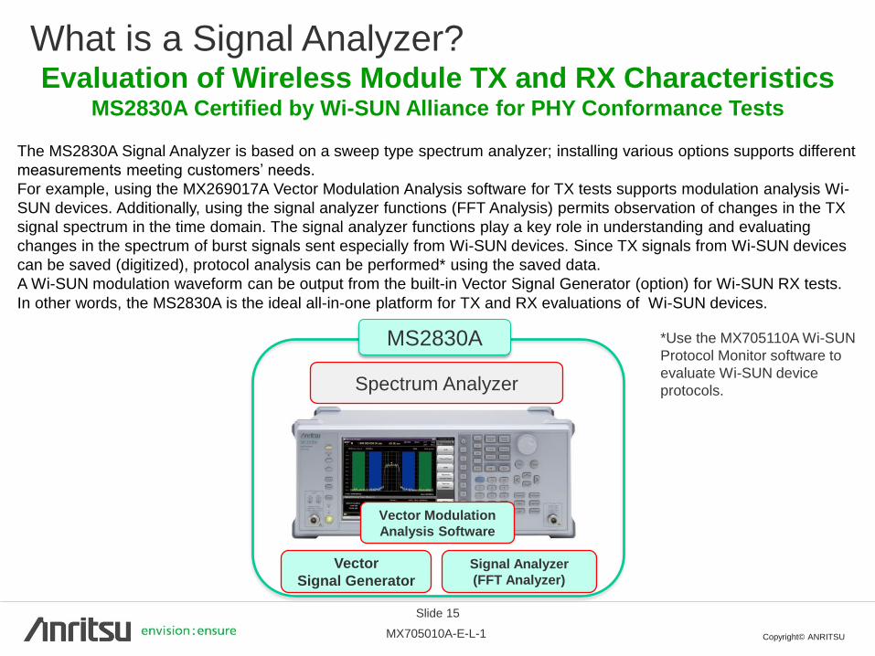
What is a Signal Analyzer?
Spectrum Analyzer
Signal Analyzer
(FFT Analyzer)
Vector
Signal Generator
Vector Modulation
Analysis Software
Evaluation of Wireless Module TX and RX Characteristics MS2830A Certified by Wi-SUN Alliance for PHY Conformance Tests
The MS2830A Signal Analyzer is based on a sweep type spectrum analyzer; installing various options supports different
measurements meeting customers’ needs.
For example, using the MX269017A Vector Modulation Analysis software for TX tests supports modulation analysis Wi-
SUN devices. Additionally, using the signal analyzer functions (FFT Analysis) permits observation of changes in the TX
signal spectrum in the time domain. The signal analyzer functions play a key role in understanding and evaluating
changes in the spectrum of burst signals sent especially from Wi-SUN devices. Since TX signals from Wi-SUN devices
can be saved (digitized), protocol analysis can be performed* using the saved data.
A Wi-SUN modulation waveform can be output from the built-in Vector Signal Generator (option) for Wi-SUN RX tests.
In other words, the MS2830A is the ideal all-in-one platform for TX and RX evaluations of Wi-SUN devices.
*Use the MX705110A Wi-SUN
Protocol Monitor software to
evaluate Wi-SUN device
protocols.
MS2830A
Copyright© ANRITSU MX705010A-E-L-1
16
Note

• United StatesAnritsu Company1155 East Collins Blvd., Suite 100, Richardson, TX 75081, U.S.A.Toll Free: 1-800-267-4878Phone: +1-972-644-1777Fax: +1-972-671-1877
• CanadaAnritsu Electronics Ltd.700 Silver Seven Road, Suite 120, Kanata, Ontario K2V 1C3, CanadaPhone: +1-613-591-2003 Fax: +1-613-591-1006
• BrazilAnritsu Eletrônica Ltda.Praça Amadeu Amaral, 27 - 1 Andar01327-010 - Bela Vista - São Paulo - SP - BrazilPhone: +55-11-3283-2511Fax: +55-11-3288-6940
• MexicoAnritsu Company, S.A. de C.V.Av. Ejército Nacional No. 579 Piso 9, Col. Granada11520 México, D.F., MéxicoPhone: +52-55-1101-2370Fax: +52-55-5254-3147
• United KingdomAnritsu EMEA Ltd.200 Capability Green, Luton, Bedfordshire, LU1 3LU, U.K.Phone: +44-1582-433200 Fax: +44-1582-731303
• FranceAnritsu S.A.12 avenue du Québec, Bâtiment Iris 1- Silic 612,91140 VILLEBON SUR YVETTE, FrancePhone: +33-1-60-92-15-50Fax: +33-1-64-46-10-65
• GermanyAnritsu GmbHNemetschek Haus, Konrad-Zuse-Platz 1 81829 München, Germany Phone: +49-89-442308-0 Fax: +49-89-442308-55
• ItalyAnritsu S.r.l.Via Elio Vittorini 129, 00144 Roma, ItalyPhone: +39-6-509-9711 Fax: +39-6-502-2425
• SwedenAnritsu ABKistagången 20B, 164 40 KISTA, SwedenPhone: +46-8-534-707-00 Fax: +46-8-534-707-30
• FinlandAnritsu ABTeknobulevardi 3-5, FI-01530 VANTAA, FinlandPhone: +358-20-741-8100Fax: +358-20-741-8111
• DenmarkAnritsu A/SKay Fiskers Plads 9, 2300 Copenhagen S, DenmarkPhone: +45-7211-2200Fax: +45-7211-2210
• RussiaAnritsu EMEA Ltd. Representation Office in RussiaTverskaya str. 16/2, bld. 1, 7th floor.Russia, 125009, MoscowPhone: +7-495-363-1694Fax: +7-495-935-8962
• United Arab EmiratesAnritsu EMEA Ltd.Dubai Liaison OfficeP O Box 500413 - Dubai Internet CityAl Thuraya Building, Tower 1, Suit 701, 7th FloorDubai, United Arab EmiratesPhone: +971-4-3670352Fax: +971-4-3688460
• IndiaAnritsu India Private Limited2nd & 3rd Floor, #837/1, Binnamangla 1st Stage, Indiranagar, 100ft Road, Bangalore - 560038, IndiaPhone: +91-80-4058-1300Fax: +91-80-4058-1301
• SingaporeAnritsu Pte. Ltd.11 Chang Charn Road, #04-01, Shriro HouseSingapore 159640Phone: +65-6282-2400Fax: +65-6282-2533
• P.R. China (Shanghai)Anritsu (China) Co., Ltd.Room 2701-2705, Tower A, New Caohejing International Business CenterNo. 391 Gui Ping Road Shanghai, 200233, P.R. ChinaPhone: +86-21-6237-0898Fax: +86-21-6237-0899
• P.R. China (Hong Kong)Anritsu Company Ltd.Unit 1006-7, 10/F., Greenfield Tower, Concordia Plaza,No. 1 Science Museum Road, Tsim Sha Tsui East, Kowloon, Hong Kong, P.R. ChinaPhone: +852-2301-4980Fax: +852-2301-3545
• JapanAnritsu Corporation8-5, Tamura-cho, Atsugi-shi, Kanagawa, 243-0016 JapanPhone: +81-46-296-1221Fax: +81-46-296-1238
• KoreaAnritsu Corporation, Ltd.5FL, 235 Pangyoyeok-ro, Bundang-gu, Seongnam-si, Gyeonggi-do, 463-400 KoreaPhone: +82-31-696-7750Fax: +82-31-696-7751
• AustraliaAnritsu Pty. Ltd.Unit 21/270 Ferntree Gully Road, Notting Hill, Victoria 3168, AustraliaPhone: +61-3-9558-8177Fax: +61-3-9558-8255
• TaiwanAnritsu Company Inc.7F, No. 316, Sec. 1, NeiHu Rd., Taipei 114, TaiwanPhone: +886-2-8751-1816Fax: +886-2-8751-1817
Specifications are subject to change without notice.
1404
Printed on Recycled Paper
Please Contact:
No. MX705010A-E-L-1-(3.00) Printed in Japan 2014-11 MG