why gd&t? - university of...
TRANSCRIPT
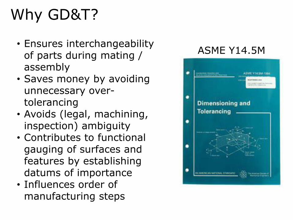
Why GD&T?
• Ensures interchangeability of parts during mating / assembly
• Saves money by avoiding unnecessary over-tolerancing
• Avoids (legal, machining, inspection) ambiguity
• Contributes to functional gauging of surfaces and features by establishing datums of importance
• Influences order of manufacturing steps
ASME Y14.5M
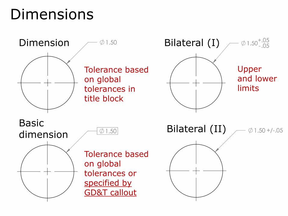
Dimensions
Dimension
Basic dimension
Tolerance based on global tolerances in title block
Tolerance based on global tolerances or specified by GD&T callout
Bilateral (I)
Bilateral (II)
Upper and lower limits

Dimensions
Limit
Max
Min
Useful for defining min. dimensions when max. would not interfere with feature / part utility

Feature Control Frame
Geometric characteristic
Secondary geometric characteristic
Feature tolerance
Feature modifier
Primary datum
Secondary datum
Tertiary datum
Datum modifier
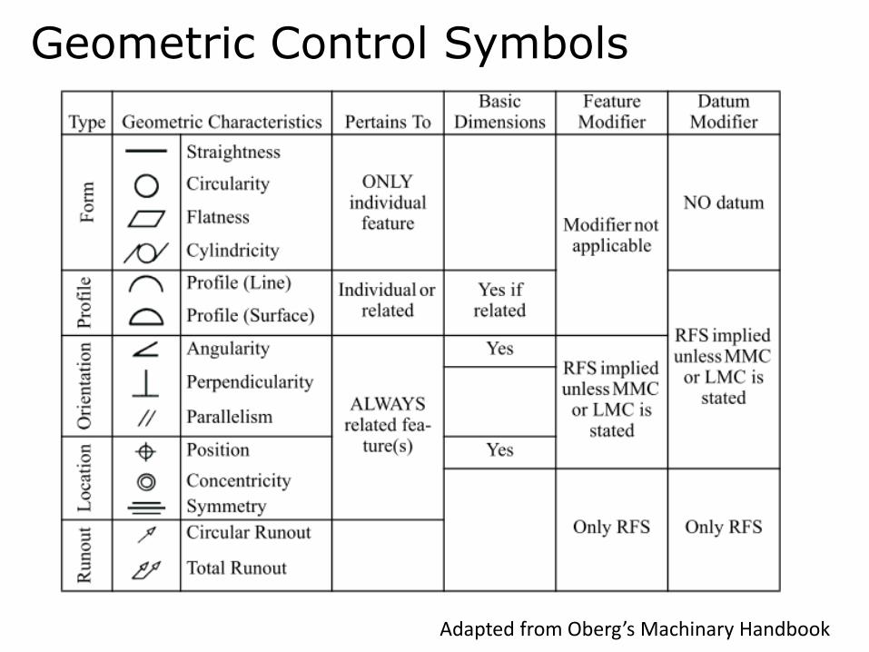
Geometric Control Symbols
Adapted from Oberg’s Machinary Handbook

Establishing Datums

Establishing Datums
Surface Plate
Right Angle Plate
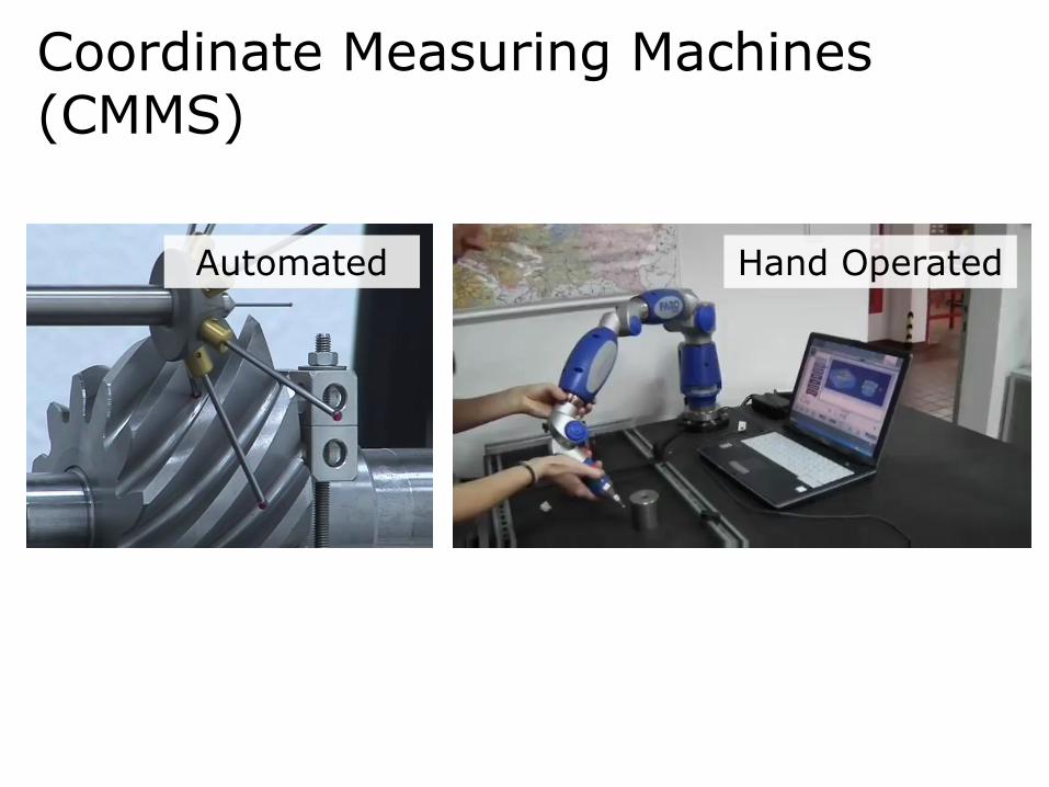
Coordinate Measuring Machines (CMMS)
Automated Hand Operated
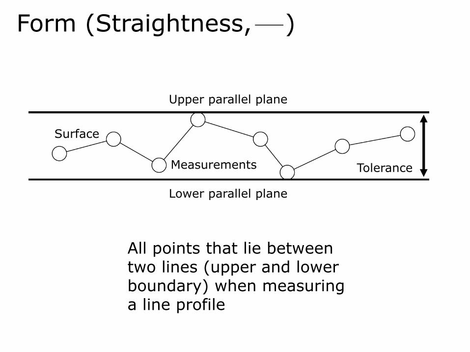
Form (Straightness, )
Surface
Measurements
Upper parallel plane
Lower parallel plane
Tolerance
All points that lie between two lines (upper and lower boundary) when measuring a line profile

Form (Circularity, )
All points of a plane perpendicular to a common axis are equidistant from that axis
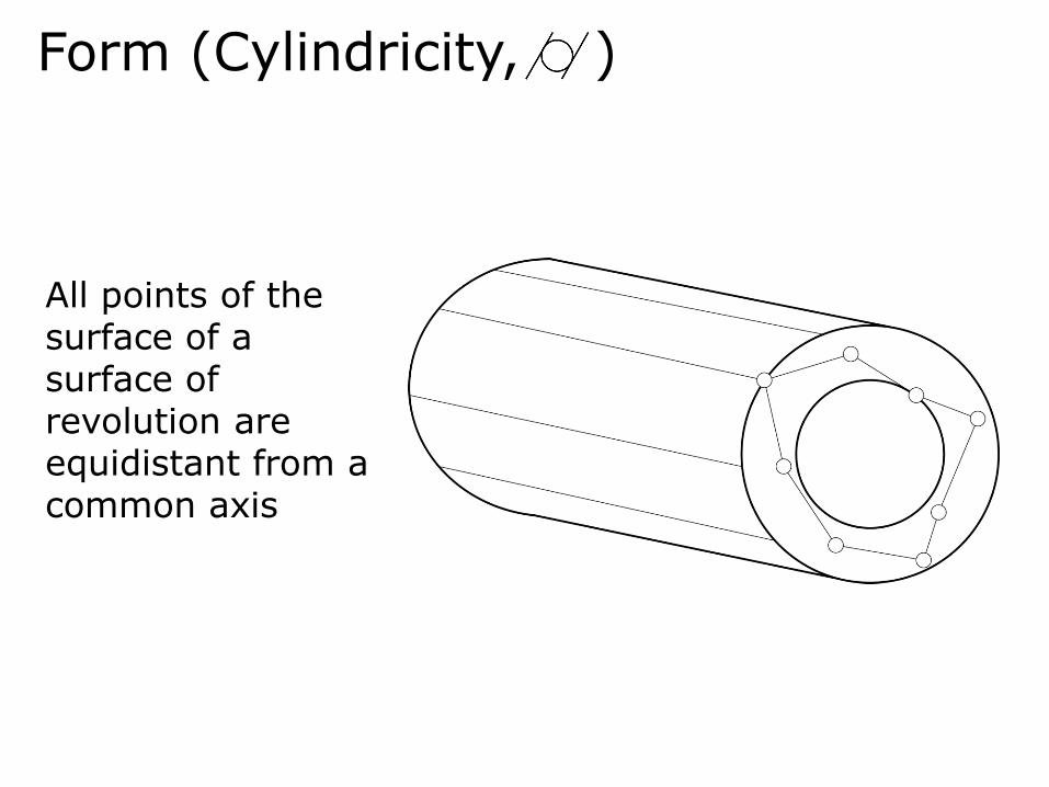
Form (Cylindricity, )
All points of the surface of a surface of revolution are equidistant from a common axis

Form (Flatness, )
The distance between all elements in one plane when measured with reference to a reference plane

Profile (Line, or Surface, )
This distance between all points of a line profile or surface profile between two surfaces of the shape of the idealized surface

Orientation (Angularity, )
The tolerance zone defined by two parallel planes or a cylinder at a specified angle from the datum plane

Orientation (Perpendicularity, )
The tolerance zone of two parallel plates perpendicular to a datum within which a feature must lie

Orientation (Parallelism, )
The tolerance zone of two parallel plates parallel to a datum within which a feature must lie

Location (Position, )
The exact location of a point, line, or surface in relation to another datum

Location (Concentricity, )
The position of an axis in relation to another datum axis

Runout (Circular, ,and Total, )
The deviation of the profile of an axisymmetric feature from a control (datum) axis

Lathe Terminology

Workholding (Collets)
Collets sizes are selected based on the stock size
Collets are located in the drawer in (or next to) the lathe

Workholding (3- and 4-Jaw Chucks)
3-Jaw Chucks• Self-centering and quick
clamping• Cannot hold irregularly shaped
work pieces
4-Jaw Chucks• Admits square
stock• Off-center turning• Mounting subject
to eccentricities
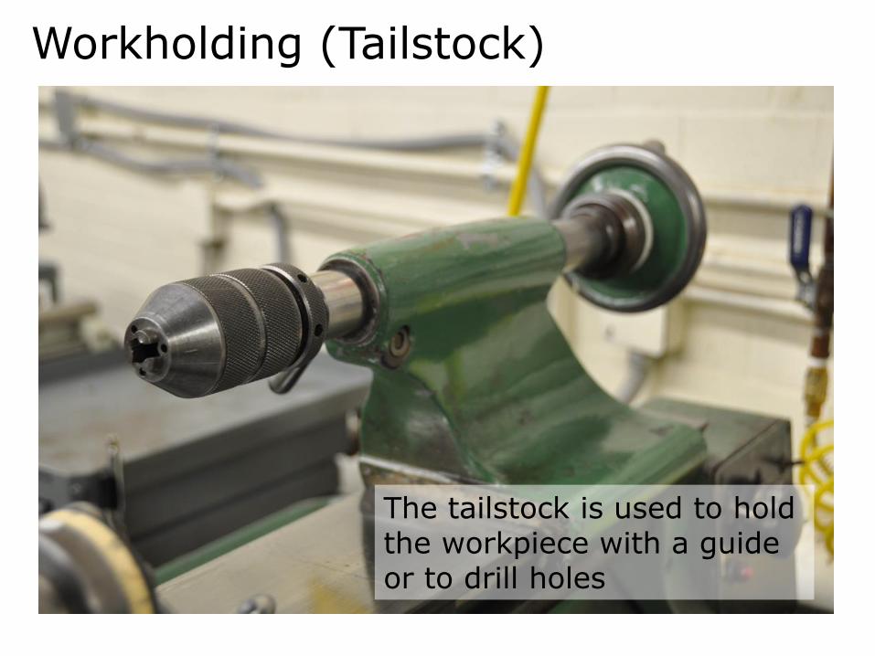
Workholding (Tailstock)
The tailstock is used to hold the workpiece with a guide or to drill holes

Tooling
Facing/turning (carbide insert)
Part-off tool
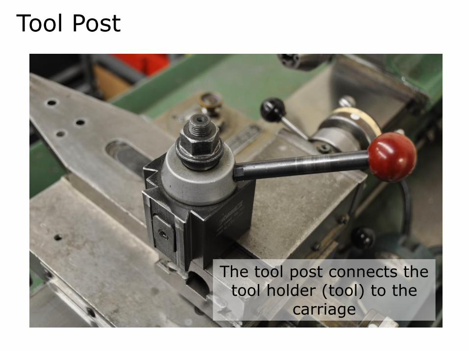
Tool Post
The tool post connects the tool holder (tool) to the
carriage
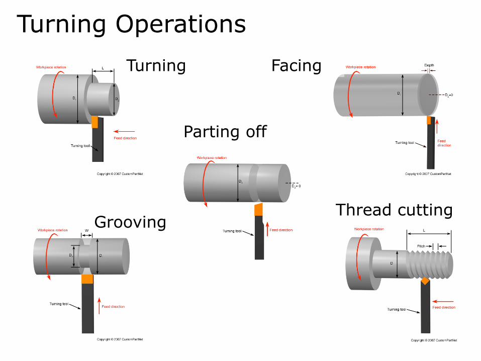
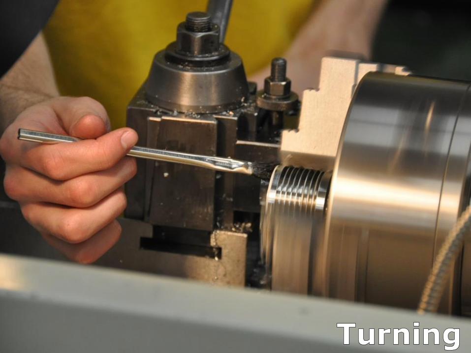
Turning Operations
Turning Facing
GroovingThread cutting
Parting off
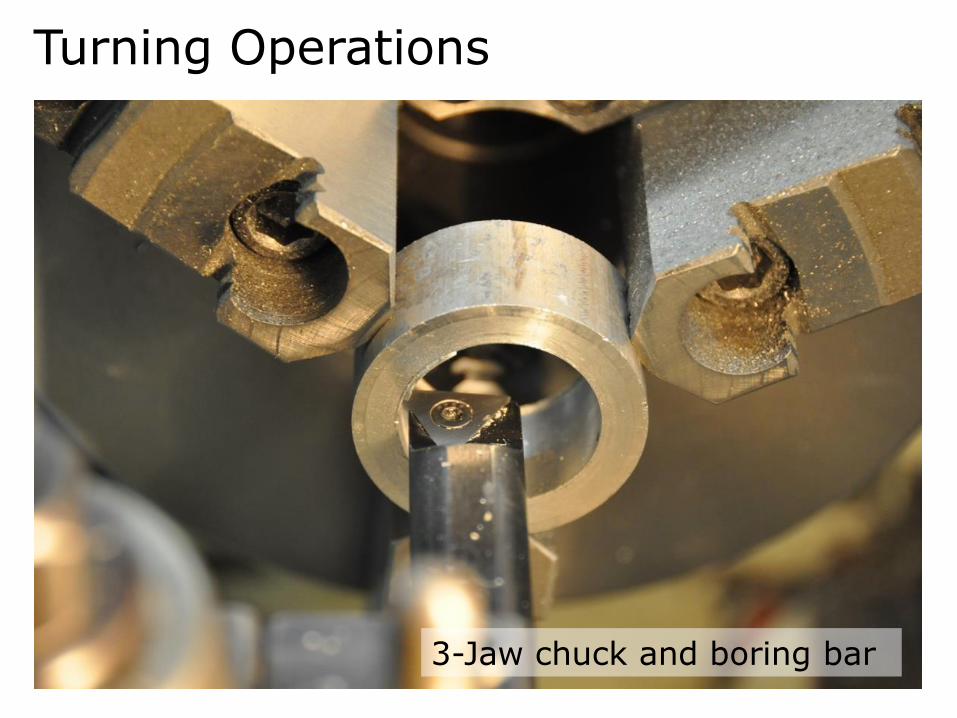
Turning Operations
3-Jaw chuck and boring bar

Turning Operations
Peck drilling

Feeds and Speeds
Spindle Speed[RPM] =4 x Cutting Speed [SFPM]
Tool Diameter [in. ]
You set this Empirically determined parameter
Provided or selected
Speed Equation for the Mill
Speed Equation for the Lathe
Spindle Speed[RPM] =4 x Cutting Speed [SFPM]
Part Diameter [in. ]

Feeds and Speeds
Roughing = 0.005”Finishing = 0.001 – 0.002”
Feed Ratein
min= Chip Load in. x
x Spindle Speed[RPM]
You set this
Determined by the speed equation

Feeds and Speeds
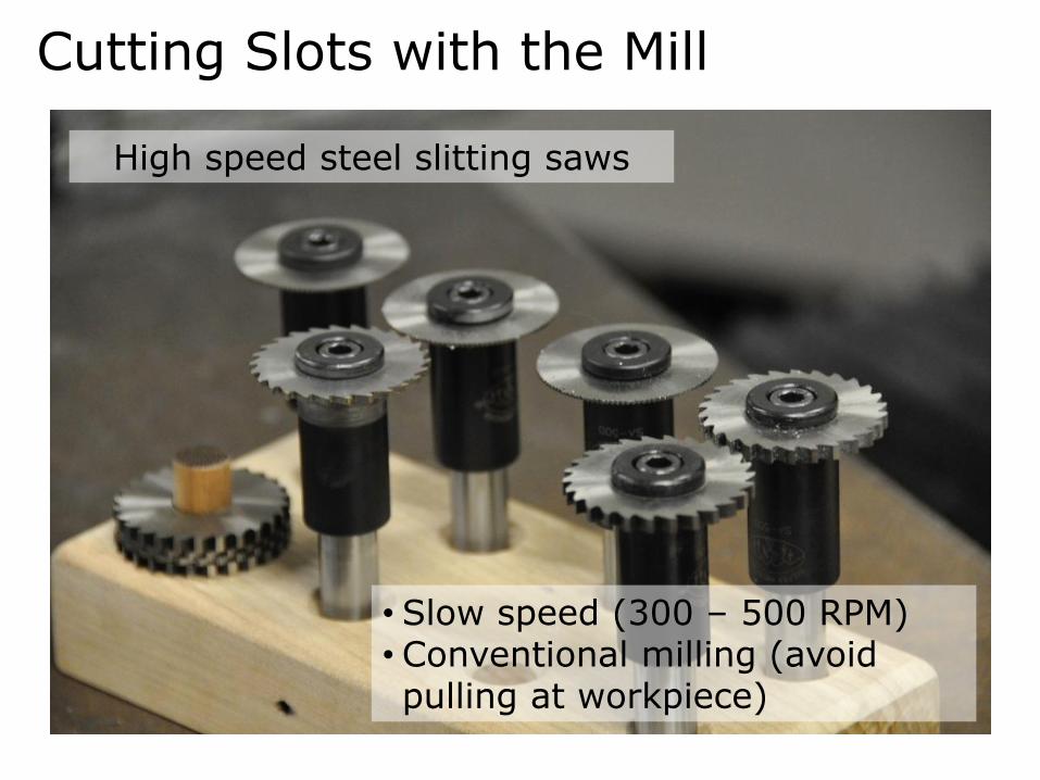
Cutting Slots with the Mill
High speed steel slitting saws
• Slow speed (300 – 500 RPM)• Conventional milling (avoid pulling at workpiece)