wheelchair lift with rotating platform 290...abstract: the motorized wheelchair lift with rotating...
TRANSCRIPT

Motorized Wheelchair Lift with Rotating Platform
By: Jonathan de la Paz Deborah Guttmann Madeline Larkin
Team 1
Client Contact: Dr. John D. Enderle
University of Connecticut 260 Glenbrook Rd, U-2157
Storrs, CT 06269 (860) 486-5521

Table of Contents: TABLE OF CONTENTS
Abstract 3 Introduction-
Background 4 Preliminary Requirements and Limitations 4 Market Research 6
Methods – Design 1 7 Design 2 13 Design 3 17 Discussion -
Optimal Design 18 Conclusion 37 Appendix A: Technical Specifications 38 Appendix B: Timeline 39 Appendix C: Budget and Parts List 40 Appendix D: Engineering Standards 41 References 42 Acknowledgements 43
2

Abstract:
The Motorized Wheelchair Lift with Rotating Platform is a fully motorized device that helps persons confined to wheelchairs access all forms of modern health care. The lift and rotational device are designed to be used during routine health care examinations, i.e. dental checkups, physical examinations and diagnostic procedures such as mammograms. This device is important to persons confined to wheelchairs as it helps position him/her more easily during a health care procedure and it makes the patient more comfortable.
3

Introduction: Background Persons who are confined to wheelchairs need access to health care professionals and diagnostic equipment. Unfortunately, this is not possible at all times due to the lack of equipment available to properly raise and rotate a patient to the proper positioning. Because this equipment is not readily available, it can be problematic for a patient confined to a wheelchair to have an accurate mammogram or get a proper magnetic resonance imaging (MRI) test. Eye exams, dental care, general physicals, and specialized procedures such as MRIs and mammograms require patients to be in a certain position, at a certain height, or to move the body in a certain way. In hospitals, most of the existing devices for these procedures are not equipped to accommodate those in wheelchairs. These persons with disabilities are unfairly faced with obstacles that do not limit accessibility for others. Therefore, a platform device is ideal for this project to make it possible for persons with disabilities to effortlessly access their healthcare procedures. The major requirement for the device is two-degrees of freedom. Meaning that it will have a vertical translation from three to nine inches and it will rotate a full 360 degrees. A small ramp is required so the patient can easily wheel onto the platform. Also, the device needs to be motorized and have a user interface that both the patient and the healthcare practitioner will be able to use. The device is also required to be transportable by means of rolling or carrying. On top of all the features that are required for the device, safety features are also necessary. Preliminary Requirements and Limitations
The Motorized Wheelchair Lift with Rotating Platform is designed to fully employ all of these requirements. The main goal of the design is to help people confined to wheelchairs access mammogram examinations and MRI testing. The fully motorized lift operates with 360-degree rotation and vertical translation of three to nine inches. The lifting feature is operated by a motor connected to a chain attached to four sprockets, which will turn up and down threaded rods. The rotational feature is also going to be run on chains and sprockets, similar to the idea of the lifting feature, except there will be no threaded rods. The second sprocket will be attached to a bolt extending downward from the turntable. The lift also has a ramp that allows for the patient to effortlessly access the platform. The lift is controlled by a basic user interface, which will allow for the patient or the healthcare practitioner to wirelessly control the lifting and rotating portions of the device. The overall cost of fabricating this project is around $1500. The Motorized Wheelchair Lift with Rotating Platform is a universal device which is adaptable to most wheelchair sizes and weights, and will allow wheelchair confined persons to access healthcare examinations in a timely and safe manner.
Wheelchairs are designed for the elderly, paraplegics, people with disabilities,
amputees and others that need to be transported due to health related issues. The reason for fabricating this device is that many health care procedures are not accessible to persons with disabilities. A wheelchair ramp calls for a specific slope, which is ADA
4

compliant, and a health care facility that does not have one may not have the room or financial means to build one. For example, portable diagnostic units may not have the proper lift device to place the patient in the machine or may not have an accessible entrance to where the entity is stationed. A portable lift device is a much more sensible solution. Overall, this device is beneficial in any location that is not accessible to persons with disabilities.
People with disabilities comprise the largest minority group, which consist of 15
percent of the US population. People with disabilities may result from disease, injury, or age and may lead to everyday use of a wheelchair to accommodate their lifestyle. Cerebral palsy, muscular dystrophy, multiple sclerosis, spinal injuries, cancer, mentally handicapped, and the elderly are all types of diseases or injuries that the population faces leading to possible wheelchair use. These individuals that encounter these types of disabilities could all benefit from The Motorized Wheelchair Lift with Rotating Platform in receiving appropriate healthcare and screening with out facing the normal obstacles due to height and movement. Depending on the progression of many diseases or the severity of certain injuries, the individual may or may not need another person to aid in operation. People with disabilities contend with physical and situational barriers that complicate everyday living including trips to the doctors. The healthcare field is in most cases unable to provide adequate healthcare to the disabled due to improper treatment and screening because the disabled does not have the means to access certain equipment for appropriate examinations.
During a patient’s stay in rehabilitation they will most likely be undergoing many
clinical tests. The person with disabilities is constantly being placed on tables, chairs, and in CT and MRI machines. This is why it is important for the Motorized Wheelchair Lift with Rotating Platform to assist in undergoing clinical tests. The lift makes the job easier for the healthcare practitioner and it more comfortable for the person confined to the wheelchair because the patient is painlessly raised and rotated to reach the desired height and angle. This is especially convenient for persons with disabilities who are obese because it may be harder for them to properly position themselves for medical procedures.
People become paralyzed for multiple reasons, such as a spinal cord injury, a birth
defect, or a stroke. If these people require the use of a wheelchair they will need a means of accessing healthcare procedures safely and effectively. Therefore, it is important to accommodate persons with disabilities with the Motorized Wheelchair Lift with Rotating Platform.
For this device safety is a major requirement. The base must be stable enough to
avert tipping if the maximum load is concentrated at any position other than the center. The motorized controls must be accessible and easily manipulated by the user no matter what his/her disability. The speed that the motor raises and rotates the platform must be within appropriate limits as to not injure the user. A manual function should be integrated in the incident of an electrical failure while the platform is in a raised position.
5

A constraint of the platform is that there are many styles and sizes of wheelchairs, so the device must be compatible with many different designs. The device must be congruent with as many types of wheelchairs as possible for it to be useful, which means it must be adaptable to multiple wheel sizes and motorized and non-motorized wheelchairs. All parts of the wheelchair must be contained within the width of the platform for it to rotate safely. The device is also constrained by the maximum amount of weight it can lift and rotate. Market Research
There are some wheelchair lifts that exist on the market for consumers, but nothing that is specific to the Motorized Wheelchair Lift with Rotating Platform’s concept. Such items include a seat that tilts to help the individual standup out of the chair, if they have a hard time raising up or lowering themselves down into the chair. There is also another rather large, in size, device that acts as an elevator for a wheelchair. This device can raise a person to a much greater height than Motorized Wheelchair Lift with Rotating Platform will, but it is extremely large for the situation that the Motorized Wheelchair Lift with Rotating Platform will accommodate for, and this device also does not rotate 360 degrees for an increase in the advantages for use. This type of lift is extremely expensive at a price near $8000 from “Adaptive Engineering LTD.”
The market also offers a wheelchair lift that permanently attaches to a vehicle,
which has a high popularity in handicapped transportation vehicles. This device is not transportable since it stays attached to the vehicle, the Motorized Wheelchair Lift with Rotating Platform however will be able to be transported for a variety of uses including storage purposes. The Chair will be vital when treating patients in doctor’s offices and in clinics, where space maybe an issue. Having the device transportable allows the healthcare provider appropriate and efficient storage when not in use, or permits the wheelchair bound individual to bring the device with them to appointments.
There is a device, however that has been registered at the US patent office in 1990, that is similar to the Motorized Wheelchair Lift with Rotating Platform idea due to its capabilities to rotate, lift and be transportable. The Wheelchair Lift Mechanism (patent # 5,040,638) operates by a pair of drums that allows for rotational and translational movement. The Motorized Wheelchair Lift with Rotating Platform differs from this device with the concept of a motorized unit. This specific device, The Wheelchair Lift Mechanism, however, could not be found on the market.
6

Methods: Design One Static and Material Analysis The platform will be lifted by a scissor jack mechanism. This is a commonly used mechanism for many similar lifts however none of those lifts have been adapted for our purposes. The mechanism works by manipulating two side by side scissors which are linked by a cross bar. The actuator will push on the cross bar. One of the legs of each of the scissor will be free to slide across the length of the base and across the length of the platform. As it does this, the angle between the legs of the scissor expand and contract based on the expansion and contraction of the actuator. As the angle decreases the legs get closer together, thus pushing up on the platform and vice versa. Analysis of the forces on the jack:
θ
Normal Force
Gravitational Force
Force of Actuator
Force on Platform
7
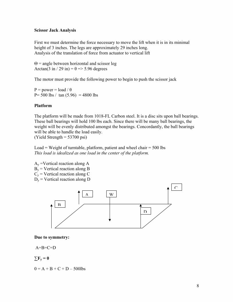
Scissor Jack Analysis First we must determine the force necessary to move the lift when it is in its minimal height of 3 inches. The legs are approximately 29 inches long. Analysis of the translation of force from actuator to vertical lift Θ = angle between horizontal and scissor leg Arctan(3 in / 29 in) = θ => 5.96 degrees The motor must provide the following power to begin to push the scissor jack P = power = load / θ P= 500 lbs / tan (5.96) = 4800 lbs Platform The platform will be made from 1018-FL Carbon steel. It is a disc sits upon ball bearings. These ball bearings will hold 100 lbs each. Since there will be many ball bearings, the weight will be evenly distributed amongst the bearings. Concordantly, the ball bearings will be able to handle the load easily. (Yield Strength = 53700 psi) Load = Weight of turntable, platform, patient and wheel chair = 500 lbs This load is idealized as one load in the center of the platform. Ay =Vertical reaction along A By = Vertical reaction along B Cy = Vertical reaction along C Dy = Vertical reaction along D
A Due to sym A=B=C=D ∑Fy = 0 0 = A + B +
B
metry:
C + D – 500lbs
D
C
W8
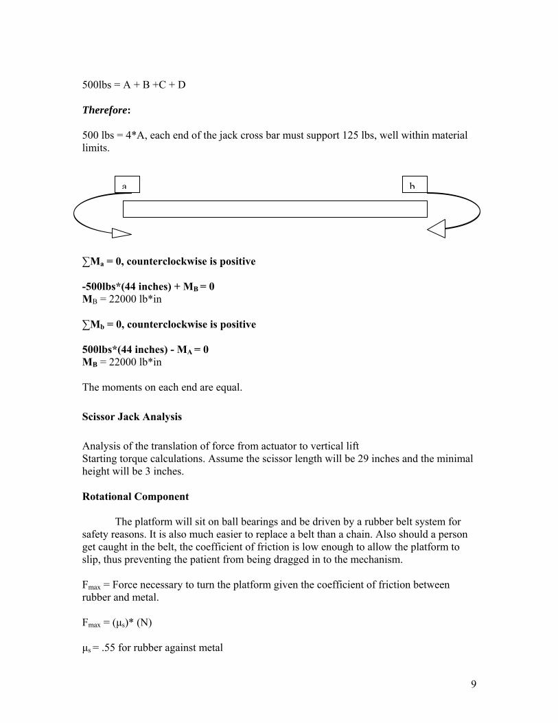
500lbs = A + B +C + D Therefore: 500 lbs = 4*A, each end of the jack cross bar must support 125 lbs, well within material limits.
ba
∑Ma = 0, counterclockwise is positive -500lbs*(44 inches) + MB = 0 MB = 22000 lb*in ∑Mb = 0, counterclockwise is positive 500lbs*(44 inches) - MA = 0 MB = 22000 lb*in The moments on each end are equal. Scissor Jack Analysis Analysis of the translation of force from actuator to vertical lift Starting torque calculations. Assume the scissor length will be 29 inches and the minimal height will be 3 inches. Rotational Component
The platform will sit on ball bearings and be driven by a rubber belt system for safety reasons. It is also much easier to replace a belt than a chain. Also should a person get caught in the belt, the coefficient of friction is low enough to allow the platform to slip, thus preventing the patient from being dragged in to the mechanism. Fmax = Force necessary to turn the platform given the coefficient of friction between rubber and metal. Fmax = (µs)* (N) µs = .55 for rubber against metal
9
Fmax = .55 * (500 lbs) = 275 lb*ft needed to rotate platform Electrical Analysis Our design involves an integration of several mechanical components to provide appropriate motion. For these parts to operate there must be an electrical circuit, which connects them to a power supply. This basic design consists of a 12V battery connected to a motor and a linear actuator. The motor will provide rotational motion and the actuator will provide the linear translation. Both the linear actuator and motor will be controlled by a microcontroller and an H-bridge circuit will drive the motor. There will be a voltage regulator to control the voltage running to the microcontroller. The control panel will consist of two toggle switches that dictate the direction of the given motor. Both are to be set at a specific speed and set in motion by the movement of the appropriate toggle switch. A microcontroller is a highly integrated chip that contains all the components comprising a controller. Typically this includes a CPU, RAM, some form of ROM, I/O ports, and timers. Unlike a general-purpose computer, which also includes all of the components, a microcontroller is designed for a very specific task – to control a particular system. Our microcontroller will accept inputs from the user interface and thus provide outputs to drive the H-bridge circuit motor control and linear actuator. A voltage regulator is a small device, or circuit, that regulates the voltage that is fed to the microprocessor. Since the required voltage of most microprocessors is less than 3.5 volts, the job of the voltage regulator is to reduce the signal running through the circuit to the microprocessor. Typically, voltage regulators are surrounded by heat sinks because they generate significant heat. Some voltage regulators, particularly those packaged as a voltage regulator module (VRM), are voltage ID (VID) programmable, which means that the microprocessor can program the voltage regulator to provide the correct voltage during power-up. An H-bridge is a specially designed circuit to drive a DC motor. The H-bridge circuit is easy to operate and requires 6 to 40 volts DC of motor power. There are two logic lever compatible inputs, A and B, and two outputs, A and B. If the A input comes in high, the output A goes high and the output B goes out low. This causes the motor to operate in one direction. If B is the driven input the opposite occurs and the motor operates in the opposite direction. If both of the inputs are low, the circuit consumes no power; the motor is not driven and can freely “coast.” In most H-bridges, when both inputs are high, the circuit self-destructs. However, it can be designed so that when both inputs are driven, the motor is shorted as braking occurs.
10
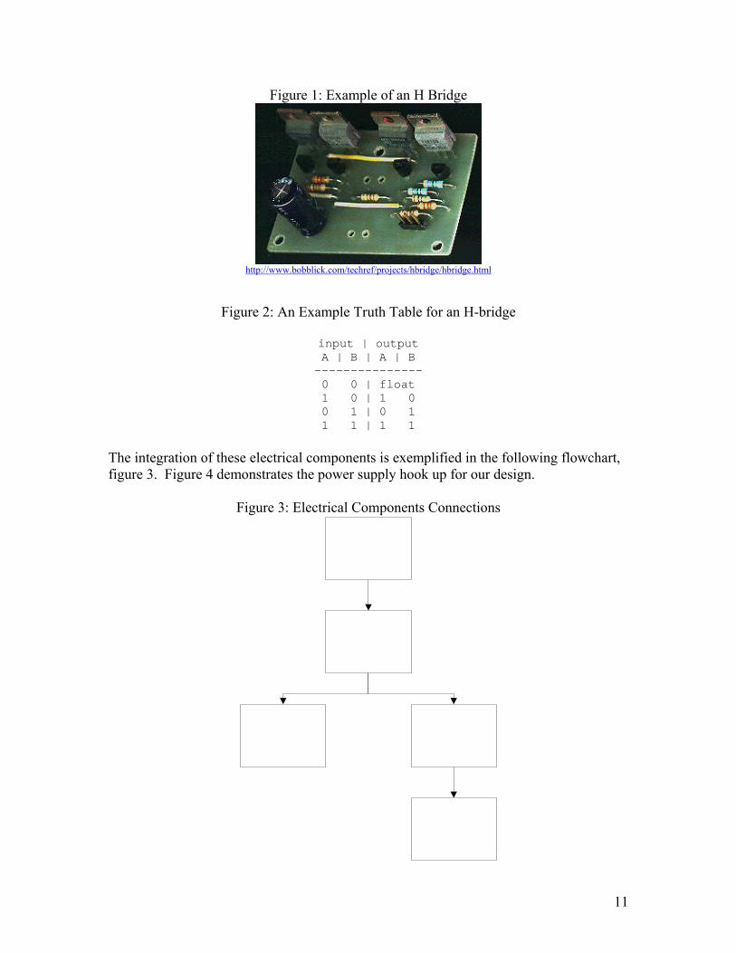
Figure 1: Example of an H Bridge
http://www.bobblick.com/techref/projects/hbridge/hbridge.html
Figure 2: An Example Truth Table for an H-bridge
input | output A | B | A | B --------------- 0 0 | float 1 0 | 1 0 0 1 | 0 1 1 1 | 1 1
The integration of these electrical components is exemplified in the following flowchart, figure 3. Figure 4 demonstrates the power supply hook up for our design.
Figure 3: Electrical Components Connections
11

Figure 7: Power Supply Connections
12

Design Two Static and Material Analysis Design II has a completely different lifting mechanism. This design utilizes a pneumatic bladder. The bladder is designed like an accordion. Metallic rings surround the bladder. When the bladder expands, the rings constrict the balloon expansion. Thus, the bladder expands uniformly along the vertical axis. This prevents random horizontal forces from the normal forces along the spherical surface of the bladder. The bladder also has the added advantage of having a slim profile when contracted. An air compressor powers the pneumatic actuator. To stabilize the platform against the horizontal forces that may arise from the actuator expansion, the platform will have four metal posts running through it at each end. This “four post bed” design will provide excellent stability for the platform. Platform Load = Weight of platform, person and wheel chair idealized as a point force Ey =Vertical reaction along E which is the center of the actuator ∑Fy = 0 0 = E – 500 lbs 500 lbs = E d Since the only vertical force exerted against thethe actuator capacity must be at least 500 lbs. “Four Post” Analysis
To stabilize the platform against the hor
actuator expansion, the platform will have four end. This “four post bed” design will provide exit locks the platform in to place, restricting any individually, will be thick enough to withstand
Loa
E
platform comes from the single actuator,
izontal forces that may arise from the metal posts running through it at each cellent stability for the platform because
horizontal movement. The posts, 500 lbs of force exerted on it with out any
13

yielding. Adding the strength of four-post system will concurrently increase the amount of horizontal force the posts can take allowing for a high factor of safety. Analysis of the stress should the load shift to one post. Assumes maximum load is placed on one of the posts. Τ = F/(π*d2) = 2000 N/ .0081 m2 = .246 MPa
Load
This is well under the yield strength of the proposed alloy given the thickness of the bar. Rotational Component For the rotational component for the lift, we opted to use the same mechanism as in Design I, this being a metallic disc, which rests on ball bearings. The turntable is driven by a belt drive. This is used to prevent the hazard of having a gear system place near the patient. W = Fmax = (µs)* (N) µs = coefficient of friction = .55 for rubber against metal W = .55 * (500 lbs) = 275 lbs needed to rotate platform Electrical Analysis
For this design we will be using pneumatic actuator and a rotational motor. Based
on our mechanical design this flow chart represents the electronic requirements of our system.
14
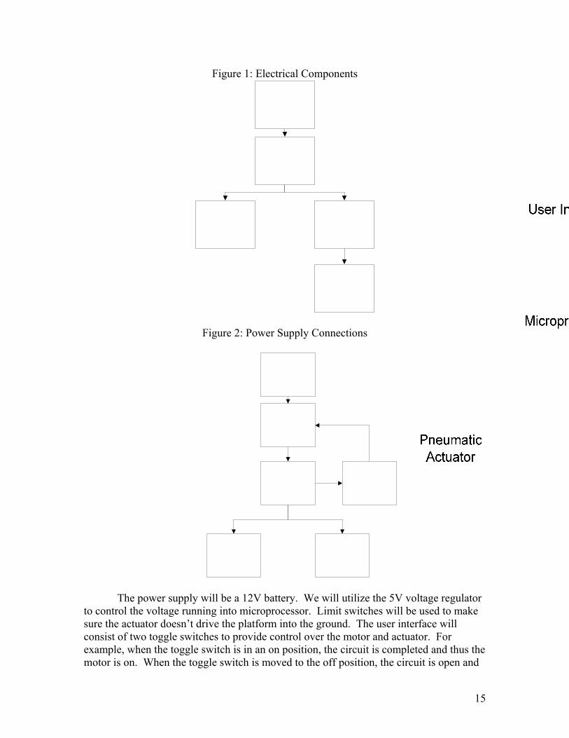
Figure 1: Electrical Components
Figure 2: Power Supply Connections
The power supply will be a 12V battery. We will utilize the 5V voltage regulator to control the voltage running into microprocessor. Limit switches will be used to make sure the actuator doesn’t drive the platform into the ground. The user interface will consist of two toggle switches to provide control over the motor and actuator. For example, when the toggle switch is in an on position, the circuit is completed and thus the motor is on. When the toggle switch is moved to the off position, the circuit is open and
15
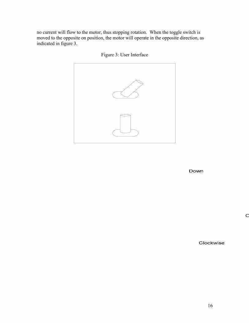
no current will flow to the motor, thus stopping rotation. When the toggle switch is moved to the opposite on position, the motor will operate in the opposite direction, as indicated in figure 3.
Figure 3: User Interface
16

Design Three Electrical Analysis This design utilizes two motors, run by two H-bridges, and controlled by a microprocessor. It will be powered by a 12 V battery and controlled by a remote control with RC signals. We are using this design for our optimal design. See Optimal Design for more details. Static and Material Analysis This design employs the two motors. The motors are attached to chains with sprockets in order to perform the rotational and lifting aspects of the project. See Optimal Design for more details.
17
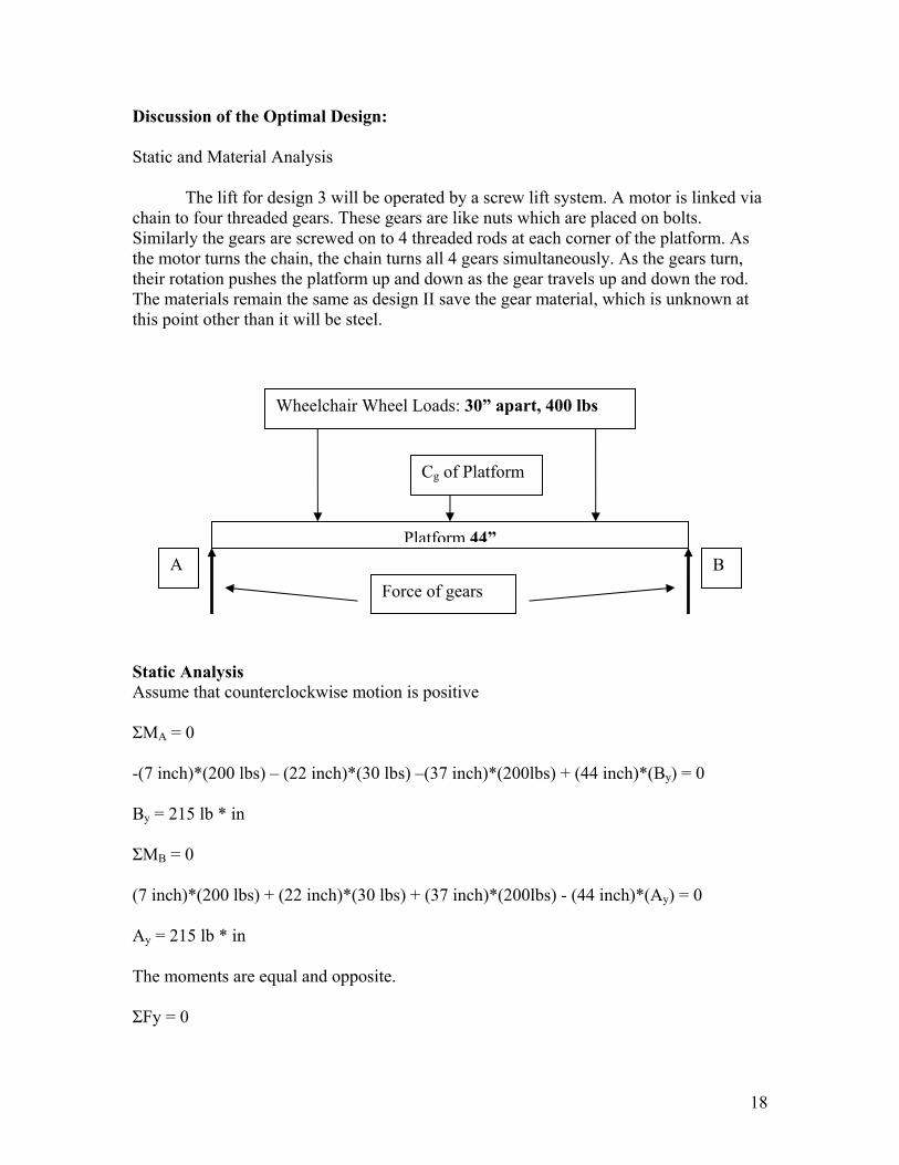
Discussion of the Optimal Design: Static and Material Analysis The lift for design 3 will be operated by a screw lift system. A motor is linked via chain to four threaded gears. These gears are like nuts which are placed on bolts. Similarly the gears are screwed on to 4 threaded rods at each corner of the platform. As the motor turns the chain, the chain turns all 4 gears simultaneously. As the gears turn, their rotation pushes the platform up and down as the gear travels up and down the rod. The materials remain the same as design II save the gear material, which is unknown at this point other than it will be steel.
Wheelchair Wheel Loads: 30” apart, 400 lbs
Static Analysis Assume that counterclockwise motion is positive ΣMA = 0 -(7 inch)*(200 lbs) – (22 inch)*(30 lbs) –(37 inch)*(200lbs) + (44 inch)*(By) = 0 By = 215 lb * in ΣMB = 0 (7 inch)*(200 lbs) + (22 inch)*(30 lbs) + (37 inch)*(200lbs) - (44 inch)*(Ay) = 0 Ay = 215 lb * in The moments are equal and opposite. ΣFy = 0
Platform 44”A B
Force of gears
Cg of Platform
18

Fg = force of gears 4Fg = 400 lbs + 30 lbs Fg = 107.5 lbs for each gear Bending Stress Σm = (M*c) / I I = (1/12)bh3 = (1/12) * (43”)*(.24”) = 86 in4
M = 215 lb in (from above) C = 1/8 in Σm = .3125 ksi. Minimal deflection will occur Screw Drive Analysis
The threads used will be Acme threads. This type of thread is the standard used for all load bearing and or industrial applications. Our design call for an Acme threaded rod of 1 inch diameter with 8 threads per inch. We used a coarse thread to ensure that the threads have sufficient strength to hold the platform in place. Torque Calculations
)(sec)(sec*
2 αµπαπµτ
lddlFd
−+
=
F = axial force placed on the threads d = pitch diameter µ = coefficient of friction α = thread angle l = pitch For our purposes: F = 500 lbs, we will assume the worst case, in that 1 gear will hold all 500 lbs d = .0625 inches µ = .8, this is the coefficient for steel on steel, the device will be lubricated, but for analysis purposes we will assume a worst case scenario l = .0625 α = 29° for Acme threads τ = 55.286 lb*in
19
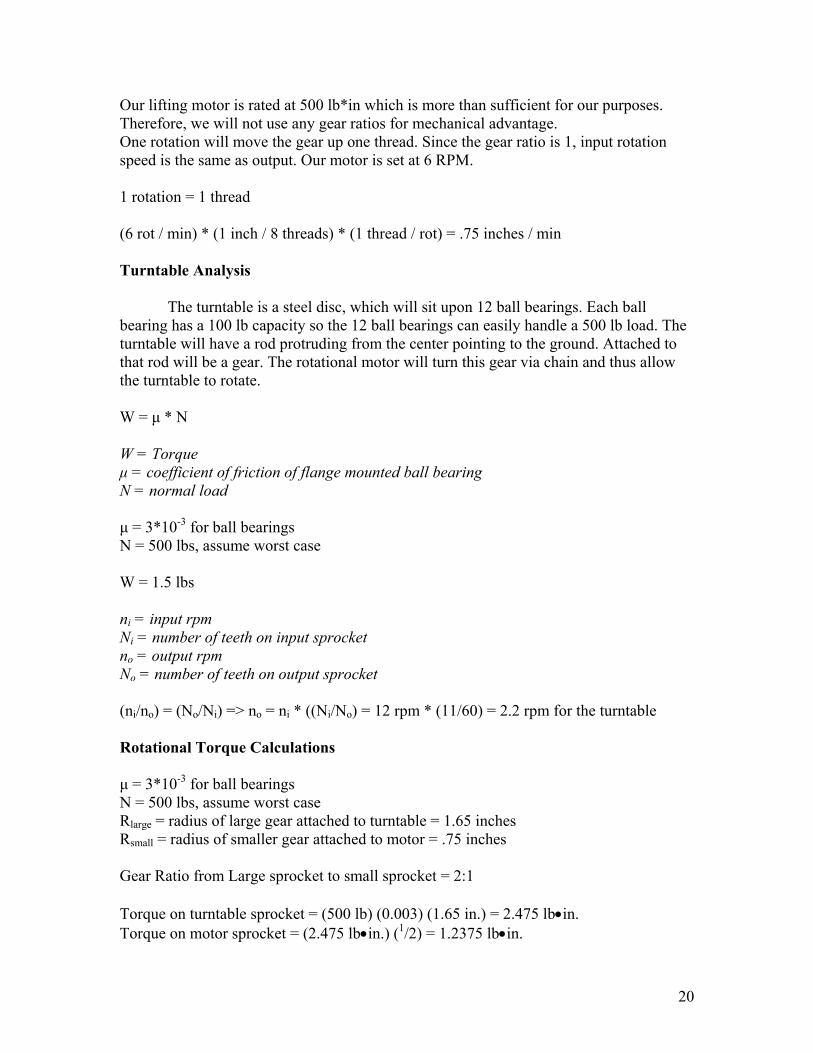
Our lifting motor is rated at 500 lb*in which is more than sufficient for our purposes. Therefore, we will not use any gear ratios for mechanical advantage. One rotation will move the gear up one thread. Since the gear ratio is 1, input rotation speed is the same as output. Our motor is set at 6 RPM. 1 rotation = 1 thread (6 rot / min) * (1 inch / 8 threads) * (1 thread / rot) = .75 inches / min Turntable Analysis
The turntable is a steel disc, which will sit upon 12 ball bearings. Each ball bearing has a 100 lb capacity so the 12 ball bearings can easily handle a 500 lb load. The turntable will have a rod protruding from the center pointing to the ground. Attached to that rod will be a gear. The rotational motor will turn this gear via chain and thus allow the turntable to rotate. W = µ * N W = Torque µ = coefficient of friction of flange mounted ball bearing N = normal load µ = 3*10-3 for ball bearings N = 500 lbs, assume worst case W = 1.5 lbs ni = input rpm Ni = number of teeth on input sprocket no = output rpm No = number of teeth on output sprocket (ni/no) = (No/Ni) => no = ni * ((Ni/No) = 12 rpm * (11/60) = 2.2 rpm for the turntable Rotational Torque Calculations µ = 3*10-3 for ball bearings N = 500 lbs, assume worst case Rlarge = radius of large gear attached to turntable = 1.65 inches Rsmall = radius of smaller gear attached to motor = .75 inches Gear Ratio from Large sprocket to small sprocket = 2:1 Torque on turntable sprocket = (500 lb) (0.003) (1.65 in.) = 2.475 lb•in. Torque on motor sprocket = (2.475 lb•in.) (1/2) = 1.2375 lb•in.
20
Initial torque is smaller than the 250 lb*in max torque of the proposed motor. While this may seem like overkill, this ensures a maximal amount of safety and mechanical reliability. Electrical Analysis The motorized wheelchair lift with rotating platform consists of two motors driven by two separate H-bridges. These will be controlled by a user interface with a joystick and wireless remote control. This will transmit an RC signal, which will be received by the microcontroller chip, which will in turn operate the appropriate H-bridge and corresponding motor. The power supply will be one 12-volt DC deep-cycle battery, with an alternate AC supply connection to recharge the battery.
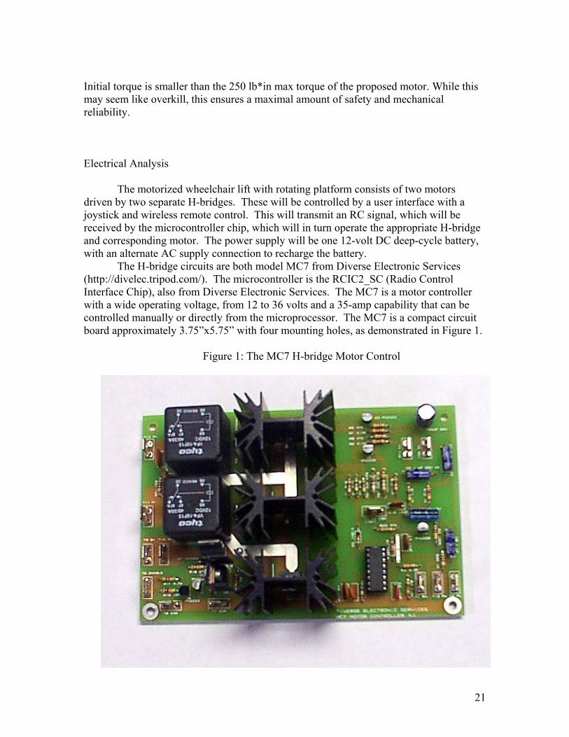
The H-bridge circuits are both model MC7 from Diverse Electronic Services (http://divelec.tripod.com/). The microcontroller is the RCIC2_SC (Radio Control Interface Chip), also from Diverse Electronic Services. The MC7 is a motor controller with a wide operating voltage, from 12 to 36 volts and a 35-amp capability that can be controlled manually or directly from the microprocessor. The MC7 is a compact circuit board approximately 3.75”x5.75” with four mounting holes, as demonstrated in Figure 1.
Figure 1: The MC7 H-bridge Motor Control
21
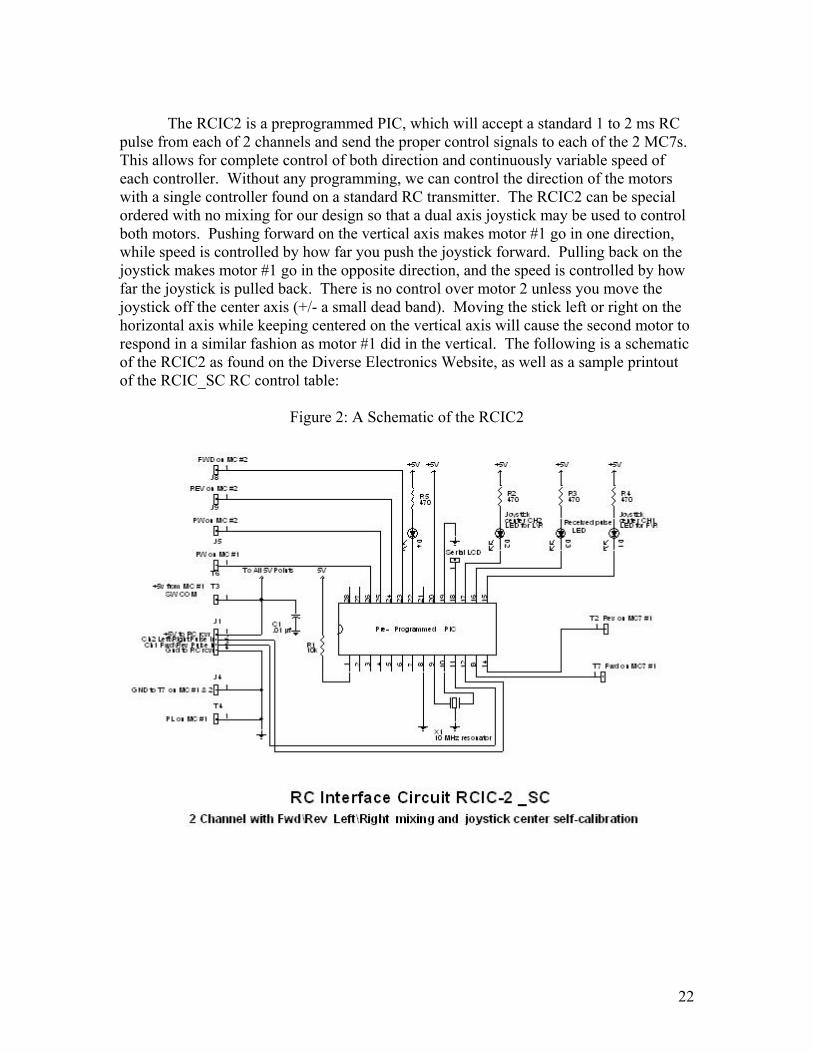
The RCIC2 is a preprogrammed PIC, which will accept a standard 1 to 2 ms RC
pulse from each of 2 channels and send the proper control signals to each of the 2 MC7s. This allows for complete control of both direction and continuously variable speed of each controller. Without any programming, we can control the direction of the motors with a single controller found on a standard RC transmitter. The RCIC2 can be special ordered with no mixing for our design so that a dual axis joystick may be used to control both motors. Pushing forward on the vertical axis makes motor #1 go in one direction, while speed is controlled by how far you push the joystick forward. Pulling back on the joystick makes motor #1 go in the opposite direction, and the speed is controlled by how far the joystick is pulled back. There is no control over motor 2 unless you move the joystick off the center axis (+/- a small dead band). Moving the stick left or right on the horizontal axis while keeping centered on the vertical axis will cause the second motor to respond in a similar fashion as motor #1 did in the vertical. The following is a schematic of the RCIC2 as found on the Diverse Electronics Website, as well as a sample printout of the RCIC_SC RC control table:
Figure 2: A Schematic of the RCIC2
22
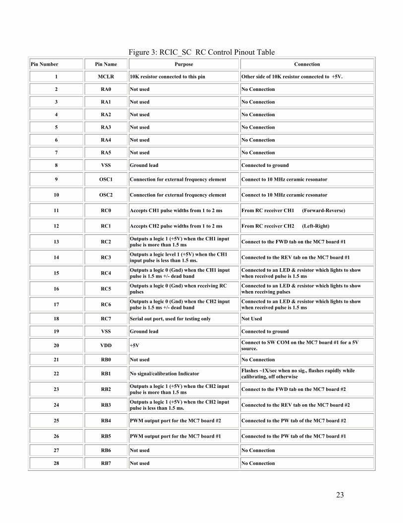
Figure 3: RCIC_SC RC Control Pinout Table Pin Number Pin Name Purpose Connection
1 MCLR 10K resistor connected to this pin Other side of 10K resistor connected to +5V.
2 RA0 Not used No Connection
3 RA1 Not used No Connection
4 RA2 Not used No Connection
5 RA3 Not used No Connection
6 RA4 Not used No Connection
7 RA5 Not used No Connection
8 VSS Ground lead Connected to ground
9 OSC1 Connection for external frequency element Connect to 10 MHz ceramic resonator
10 OSC2 Connection for external frequency element Connect to 10 MHz ceramic resonator
11 RC0 Accepts CH1 pulse widths from 1 to 2 ms From RC receiver CH1 (Forward-Reverse)
12 RC1 Accepts CH2 pulse widths from 1 to 2 ms From RC receiver CH2 (Left-Right)
13 RC2 Outputs a logic 1 (+5V) when the CH1 input pulse is more than 1.5 ms Connect to the FWD tab on the MC7 board #1
14 RC3 Outputs a logic level 1 (+5V) when the CH1 input pulse is less than 1.5 ms. Connected to the REV tab on the MC7 board #1
15 RC4 Outputs a logic 0 (Gnd) when the CH1 input pulse is 1.5 ms +/- dead band
Connected to an LED & resistor which lights to show when received pulse is 1.5 ms
16 RC5 Outputs a logic 0 (Gnd) when receiving RC pulses
Connected to an LED & resistor which lights to show when receiving pulses
17 RC6 Outputs a logic 0 (Gnd) when the CH2 input pulse is 1.5 ms +/- dead band
Connected to an LED & resistor which lights to show when received pulse is 1.5 ms
18 RC7 Serial out port, used for testing only Not Used
19 VSS Ground lead Connected to ground
20 VDD +5V Connect to SW COM on the MC7 board #1 for a 5V source.
21 RB0 Not used No Connection
22 RB1 No signal/calibration Indicator Flashes ~1X/sec when no sig., flashes rapidly while calibrating, off otherwise
23 RB2 Outputs a logic 1 (+5V) when the CH2 input pulse is more than 1.5 ms Connect to the FWD tab on the MC7 board #2
24 RB3 Outputs a logic 1 (+5V) when the CH2 input pulse is less than 1.5 ms. Connected to the REV tab on the MC7 board #2
25 RB4 PWM output port for the MC7 board #2 Connected to the PW tab of the MC7 board #2
26 RB5 PWM output port for the MC7 board #1 Connected to the PW tab of the MC7 board #1
27 RB6 Not used No Connection
28 RB7 Not used No Connection
23
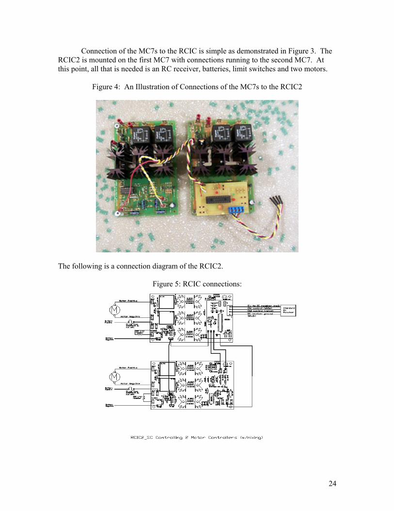
Connection of the MC7s to the RCIC is simple as demonstrated in Figure 3. The RCIC2 is mounted on the first MC7 with connections running to the second MC7. At this point, all that is needed is an RC receiver, batteries, limit switches and two motors.
Figure 4: An Illustration of Connections of the MC7s to the RCIC2
The following is a connection diagram of the RCIC2.
Figure 5: RCIC connections:
24

Connection to the receiver will also be relatively simple, as the RCIC comes complete with 4 universal leads (one red for the +5V connection, one black for the negative connection, 1 white for the channel 1 output and 1 yellow for the channel 2 output). These leads will enable us to connect to the receiver regardless of what brand we purchase. The final component to the electrical design is the addition of limit switches. These will control how far the motors run so as to keep the motor from driving the platform off the threaded rods, or even worse, into the ground. The following is a final overview of our electrical system for the optimal design. Figure 6 is a flowchart of the connections of the basic electrical components. Figure 7 demonstrates the flow of power through the system.
Figure 6: Electrical Components Connections
25

Figure 7: Power Supply Connections
Power Requirements: There are two motors in this design, one for rotational motion and one for translational motion. The full load ampage for both motors is 6.5 amps. The battery can supply 28 amps for 20 hours and thus has a capacity of 560 amp hours. Since the current divided by the full load amps determines the battery life, our battery can last 86 hours without being recharged. Based on the translational velocity calculated in the mechanical analysis, we can use dimensional analysis to calculate the number of cycles that can be run per battery life. 86 hrs (60min/1hr)(.75 in/min)(1 cycle/6 in) = 645 cycles The rotational motor also has a full load amp of 6.5 and a full load torque of 250 lbin. It is also a 12 VDC motor with a 1/15 HP and 12 RPMs. The same battery supplies power to both. The rotational motor can run for 86 hours when used solely for rotation and run continuously until the battery dies. When both of the motors are run together, the battery can last for 31 hours. Since this is more than a day, run continuously, this is plenty long enough for our specifications.
26
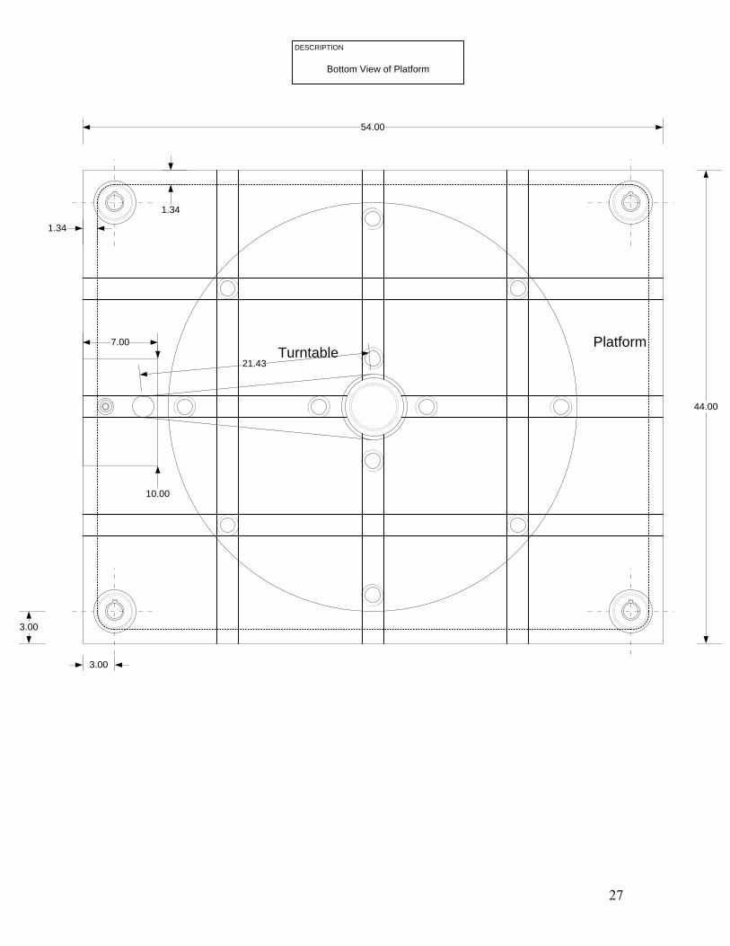
DESCRIPTION
Bottom View of Platform
7.00
10.00
TurntablePlatform
44.00
54.00
1.34
1.34
3.00
3.00
21.43
27
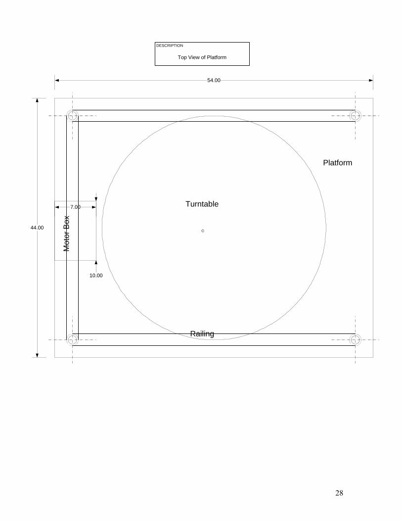
7.00
10.00
Mot
or B
ox
DESCRIPTION
Top View of Platform
Railing
Turntable
Platform
44.00
54.00
28
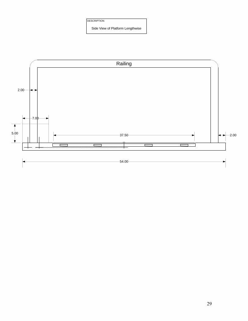
7.00
5.00
DESCRIPTION
Side View of Platform Lengthwise
Railing
54.00
2.00
2.00
37.50
29
2.00
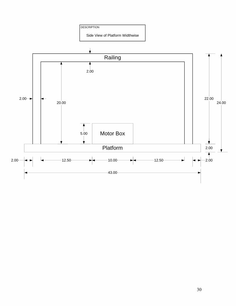
DESCRIPTION
Side View of Platform Widthwise
2.00 12.50 12.50
2.00 22.00
2.00
20.00
10.00
5.00
2.00
43.00
Motor Box
Railing
Platform
24.00
30

54.00
44.00
3.00
3.00 48.00 3.00
19.00
19.00
3.00
DESCRIPTION
Top View of Base
Base
31

50.00
20.50
0.50
20.00
2.20
2.00
DESCRIPTION
Side View of Base Lengthwise
Base
42.40
32

2.20
DESCRIPTION
Side View of Base Widthwise
2.20 13.20
20.00
0.50
20.00
10.00
44.00
Base
20.50
1.60 1.60
13.20
33
3.203.20 12.20
0.50
10.00
44.00
Base
1.60 1.60
2.00
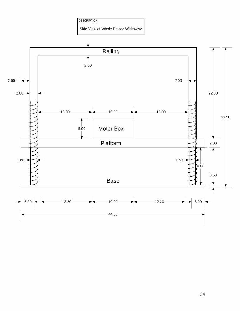
DESCRIPTION
Side View of Whole Device Widthwise
2.00
13.00 13.00
2.00
2.00
10.00
5.00
2.00
Motor Box
Railing
Platform
9.00
22.00
33.50
12.20
34
54.00
33.50
0.50
2.20
1.60
Base
46.40
5.00
46.00
2.00
2.002.00
2.00
R 2.00
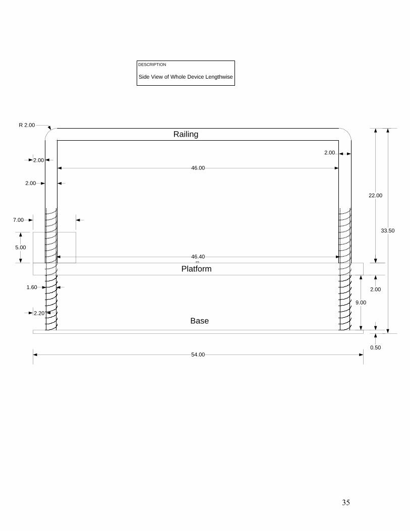
DESCRIPTION
Side View of Whole Device Lengthwise
Platform
Railing
9.00
7.00
22.00
35

7.00
10.00
DESCRIPTION
Top View of Platform without Railings
TurntablePlatform
44.00
54.00
12.50 11.50 11.50 12.50
10.00
9.00
9.00
10.00
36

Conclusion:
The optimal design is basically going to be Design Number Three. This is a very sound idea seeing as there is a lift in the machine shop that has the same basic principles of running on gears and chains, but with no motor. The lift is going to be made to do exactly what it is supposed to, have a vertical lift of three to nine inches and have a rotational axis of 360 degrees. This lift will run on motors, sprockets and chains to accomplish the aforementioned. Safety features as of right now, include limit switches and possibly a safety skirt to go around the threaded rods when in the raised position. All of the standards from ADA and ASME have been looked at, and the lift will be fully compliant with them. As of right now, the parts list is under budget seeing as the metal will be purchased from the machine shop. This device will be used to help people who are confined to wheelchairs.
37
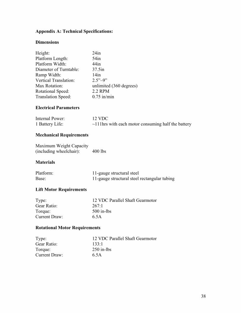
Appendix A: Technical Specifications: Dimensions Height: 24in Platform Length: 54in Platform Width: 44in Diameter of Turntable: 37.5in Ramp Width: 14in Vertical Translation: 2.5”–9” Max Rotation: unlimited (360 degrees) Rotational Speed: 2.2 RPM Translation Speed: 0.75 in/min Electrical Parameters Internal Power: 12 VDC 1 Battery Life: ~111hrs with each motor consuming half the battery Mechanical Requirements Maximum Weight Capacity (including wheelchair): 400 lbs Materials Platform: 11-gauge structural steel Base: 11-gauge structural steel rectangular tubing Lift Motor Requirements Type: 12 VDC Parallel Shaft Gearmotor Gear Ratio: 267:1 Torque: 500 in-lbs Current Draw: 6.5A Rotational Motor Requirements Type: 12 VDC Parallel Shaft Gearmotor Gear Ratio: 133:1 Torque: 250 in-lbs Current Draw: 6.5A
38

Appendix B: Timeline:
39
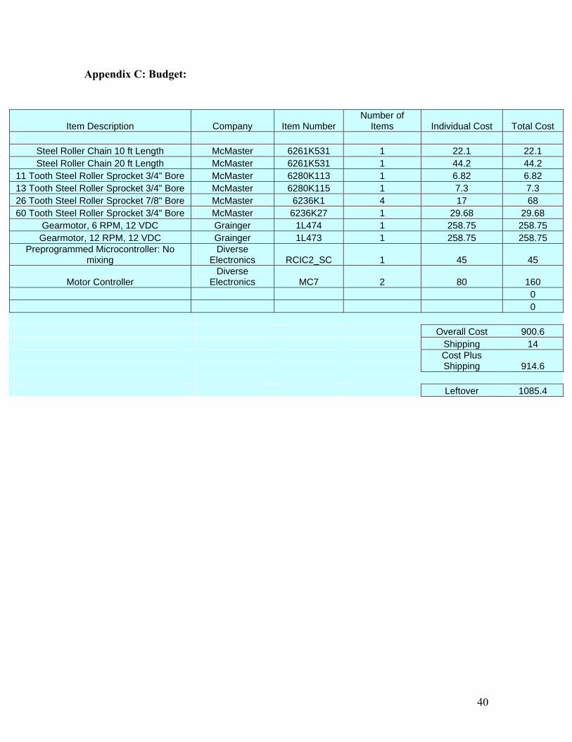
Appendix C: Budget:
Item Description Company Item Number Number of
Items Individual Cost Total Cost
Steel Roller Chain 10 ft Length McMaster 6261K531 1 22.1 22.1 Steel Roller Chain 20 ft Length McMaster 6261K531 1 44.2 44.2
11 Tooth Steel Roller Sprocket 3/4" Bore McMaster 6280K113 1 6.82 6.82 13 Tooth Steel Roller Sprocket 3/4" Bore McMaster 6280K115 1 7.3 7.3 26 Tooth Steel Roller Sprocket 7/8" Bore McMaster 6236K1 4 17 68 60 Tooth Steel Roller Sprocket 3/4" Bore McMaster 6236K27 1 29.68 29.68
Gearmotor, 6 RPM, 12 VDC Grainger 1L474 1 258.75 258.75 Gearmotor, 12 RPM, 12 VDC Grainger 1L473 1 258.75 258.75
Preprogrammed Microcontroller: No mixing
Diverse Electronics RCIC2_SC 1 45 45
Motor Controller Diverse
Electronics MC7 2 80 160 0 0 Overall Cost 900.6 Shipping 14
Cost Plus Shipping 914.6
Leftover 1085.4
40

Appendix D: Engineering Standards: The engineering standards for this project are defined in the ADA Standards for Accessible Design. This has been outlined by the United States Department of Justice. This booklet is for the rites of people confined to wheelchairs and all of the design standards that go along with it. The ADA requires that the least possible slope be used for any ramp. The maximum slope will be 1:12 (Section 4.8.2). Section 4.13.7 Two Doors in Series states that the minimum maneuvering clearance at two doors in series is 48 inches. Therefore the width of the device and diameter of the rotating platform fulfill this requirement because they are only 48 and 38 inches, respectively. This will allow the lift to enter any room in the hospital, which is its intended purpose. Section 4.2.4.3 talks about clear floor or ground spaces for wheelchairs. Ground and floor surfaces shall be stable, firm and slip-resistant. The lift complies with the code because on the ramp there will be slip-resistant materials, and from the analysis of the materials, we know that everything will be sturdy enough the hold the given weight. Section 4.8.7 is about edge protection, meaning that ramps and landings with drop-offs should have curbs, walls, railings or projecting surfaces which will prevent people from slipping off the ramp. The lift will be equipped with railings on three of the four sides, and the ramp does not have a significant slope therefore it is unnecessary to have anything on the side of the ramp. Section 4.27.4 requires that controls and operating mechanisms shall be operable with one hand and shall not require tight grasping, twisting of the arm or pinching. The force to activate the controls can be no greater than 5 lbf. The projected control for use right now is the size of an automatic car starter. Therefore, there will be no problems with the ADA standards. The Motorized Wheelchair Lift with Rotating Platform is environmentally safe. It is designed to be used indoors, i.e. in a hospital and is going to run on a battery. Since it will run on a battery, there will be no harmful toxins emitted into the air. This device is a class one device it presents minimal potential for harm to the user. The only harm that this device can cause to the user is if it the directions are not read, resulting in the lift being used improperly. Also, this device will not be used in vivo, so it will not take very long for the device to be approved.
The parts being ordered for this project are from well-known companies like Grainger and McMaster. All materials are ready to ship almost immediately because they are common. By ordering items from the same companies, the compatibility issue is reduced. Also, these companies have warrantees and some of them will even come out to fix a broken part.
41

Acknowledgements:
The team would like to thank Serge and Rich in the machine shop for all of their help looking for parts and for advice. We would also like to thank Chris Liebler and Francisco Rodriguez-Campos for their help and support building our EKGs.
42

References: www.mcmaster.com www.grainger.com www.usdoj.gov/crt/ada/stdspdf.htm Diverse Electronics Website http://www.bobblick.com/techref/projects/hbridge/hbridge.html
43