what is a harmonic the typical definition for a harmonic is “ a sinusoidal component of a...
TRANSCRIPT

What is a HarmonicWhat is a Harmonic The typical definition for a harmonic is The typical definition for a harmonic is “ “ a sinusoidal component of a periodic a sinusoidal component of a periodic
wave or quantity having a frequency that is wave or quantity having a frequency that is an integral multiple of the fundamental an integral multiple of the fundamental frequency.frequency.””
Some loads cause the voltage and current Some loads cause the voltage and current waveforms to lose there pure sine wave waveforms to lose there pure sine wave appearance and become distorted. This appearance and become distorted. This distortion may consist of mainly harmonics distortion may consist of mainly harmonics which depending on the type of load and which depending on the type of load and system impedancessystem impedances

Harmonic sourcesHarmonic sources
1- Harmonic Sources from Commercial Loads
Commercial facilities such as office complexes, department stores, hospitals, and Internet data centers having
high-efficiency fluorescent lighting with electronic ballasts, adjustable-speed drives for the heating, ventilation and air conditioning (HVAC) loads, elevator drives, and sensitive electronic equipment supplied by single-phase switch-mode power supplies .
1.1 Single-phase power supplies
-Electronic power converter loads produce harmonic currents which consider the most important class of nonlinear loads in the
power system . -The percentage of load that contains electronic power supplies
is increased with the increasing of using personal computers in every building and Equipment includes adjustable-speed motor drives, electronic power supplies, dc motor drives, battery chargers, electronic ballasts.

There are two common types of single-phase power supplies.
-Older technologies use ac-side voltage control methods, such as transformers, to reduce voltages to the level required for the dc bus .
- Newer-technology switch-mode power supplies use dc-to-dc conversion techniques to achieve a smooth dc output with small, lightweight components.The input diode bridge is directly connected to the ac line, eliminating the transformer .
switch-mode power supplies is a very high third-harmonic content in the current
1.2 Fluorescent lighting
Lighting typically accounts for 40 to 60 percent of a commercial buildingLoad , Fluorescent lights are a popular choice for energy savings
Fluorescent lights are discharge lamps; thus they require a ballast toprovide a high initial voltage to initiate the discharge for the electriccurrent to flow between two electrodes in the fluorescent tube .There are two types of ballasts, magnetic and electronic-:
A standard magnetic ballast is simply made up of an iron-core transformer with a capacitor encased in an insulating material , magnetic ballast can drive one or two fluorescent lamps
An electronic ballast use a switch-mode–type power supply to convert the incoming fundamental frequency voltage to a much higher frequency voltage typically in the range of 25 to 40 kHz .
A single electronic ballast typically can drive up to four fluorescent lamps
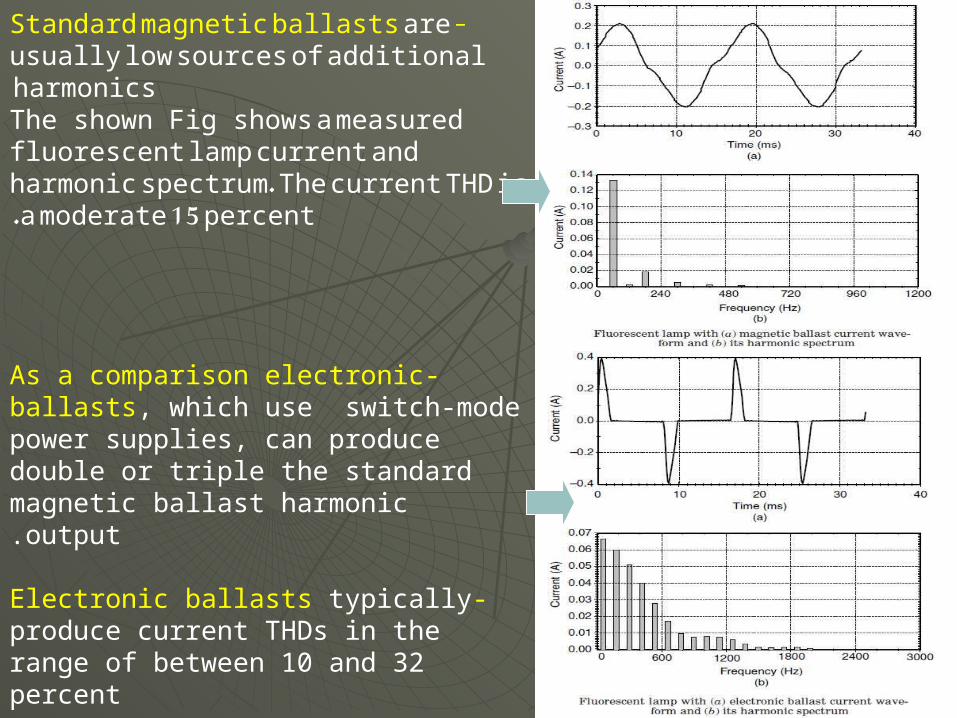
-Standard magnetic ballasts are usually low sources of additional harmonics The shown Fig shows a measured fluorescent lamp current and harmonic spectrum. The current THD is a moderate 15 percent .
-As a comparison electronic ballasts, which use switch-mode power supplies, can produce double or triple the standard magnetic ballast harmonic output.
-Electronic ballasts typically produce current THDs in the range of between 10 and 32 percent
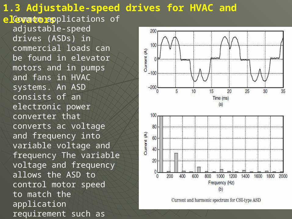
1.3 Adjustable-speed drives for HVAC and elevators
Common applications of adjustable-speed drives (ASDs) in commercial loads can be found in elevator motors and in pumps and fans in HVAC systems. An ASD consists of an electronic power converter that converts ac voltage and frequency into variable voltage and frequency The variable voltage and frequency allows the ASD to control motor speedto match the application requirement such as slowing a pump or fan.
2 -Harmonic Sources from Industrial Loads
Modern industrial facilities are characterized by the widespread application of nonlinear loads. These loads can make up a significant portion of the total facility loads and inject harmonic currents into the power system, causing harmonic distortion in the voltage. This harmonic problem is compounded by the fact that these nonlinear loads have a relatively low power factor .The application of power factor correction capacitors can potentially magnify harmonic currents from the nonlinear loads, giving rise to resonance conditions within the facility. Resonance conditions cause motor and transformer overheating, and misoperation of sensitive electronic equipment. Nonlinear industrial loads can generally be grouped into three categories: three-phase power converters, arcing devices, and saturable devices.
2.1 Three-phase power converters
Three-phase electronic power converters differ from single-phase converters mainly because they do not generate third-harmonic currents .
This is a great advantage because the third-harmonic current is the largest component of harmonics .

they can still be significant sources of harmonics at their characteristic frequencies, as shown in Fig. This is a typical current source type of adjustable-speed drive. The harmonic spectrum given in Fig
Voltage source inverter drives (suchas PWM-type drives) can have much higher distortion levels as shownin Fig. The input to the PWM drive is generally designed like a three-phase version of the switch-mode power supply in computers. The rectifier feeds directly from the ac bus to a large capacitor on the dc busthe capacitor is charged in very shortpulses, creating the distinctive “rabbit ear” ac-side current waveform with very high distortion. PWM drives are now being applied for loads up to 500 horsepower (hp) .
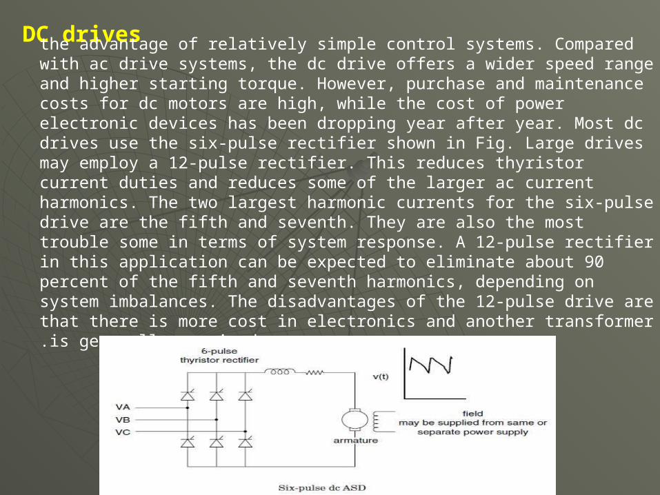
DC drivesthe advantage of relatively simple control systems. Compared with ac drive systems, the dc drive offers a wider speed range and higher starting torque. However, purchase and maintenance costs for dc motors are high, while the cost of power electronic devices has been dropping year after year. Most dc drives use the six-pulse rectifier shown in Fig. Large drives may employ a 12-pulse rectifier. This reduces thyristor current duties and reduces some of the larger ac current harmonics. The two largest harmonic currents for the six-pulse drive are the fifth and seventh. They are also the most trouble some in terms of system response. A 12-pulse rectifier in this application can be expected to eliminate about 90 percent of the fifth and seventh harmonics, depending on system imbalances. The disadvantages of the 12-pulse drive are that there is more cost in electronics and another transformer is generally required.
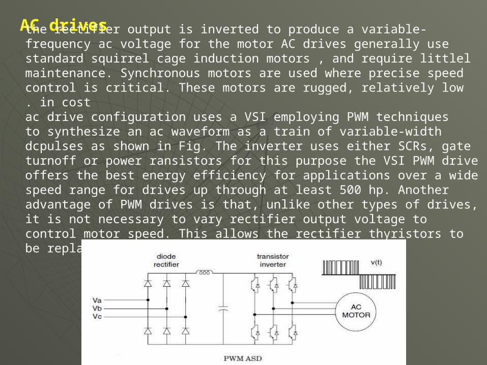
AC drives the rectifier output is inverted to produce a variable-frequency ac voltage for the motor AC drives generally use standard squirrel cage induction motors , and require littlel maintenance. Synchronous motors are used where precise speed control is critical. These motors are rugged, relatively low in cost.
ac drive configuration uses a VSI employing PWM techniquesto synthesize an ac waveform as a train of variable-width dcpulses as shown in Fig. The inverter uses either SCRs, gate turnoff or power ransistors for this purpose the VSI PWM drive offers the best energy efficiency for applications over a wide speed range for drives up through at least 500 hp. Another advantage of PWM drives is that, unlike other types of drives, it is not necessary to vary rectifier output voltage to control motor speed. This allows the rectifier thyristors to be replaced with diodes

Very high power drives employ SCRs and inverters. These may be 6- pulse, as shown in Fig. 5.18, or like large dc drives, 12-pulse. VSI drives (Fig. a) are limited to applications that do not require rapid changes in speed. CSI drives (Fig. b) have good acceleration/decelerationcharacteristics but require a motor with a leading power factor the CSI drive must be designed for use with a specific motor. Thyristors in current source inverters must be protected against inductive voltage spikes, which increases the cost of this type of drive.
Impact of operating condition
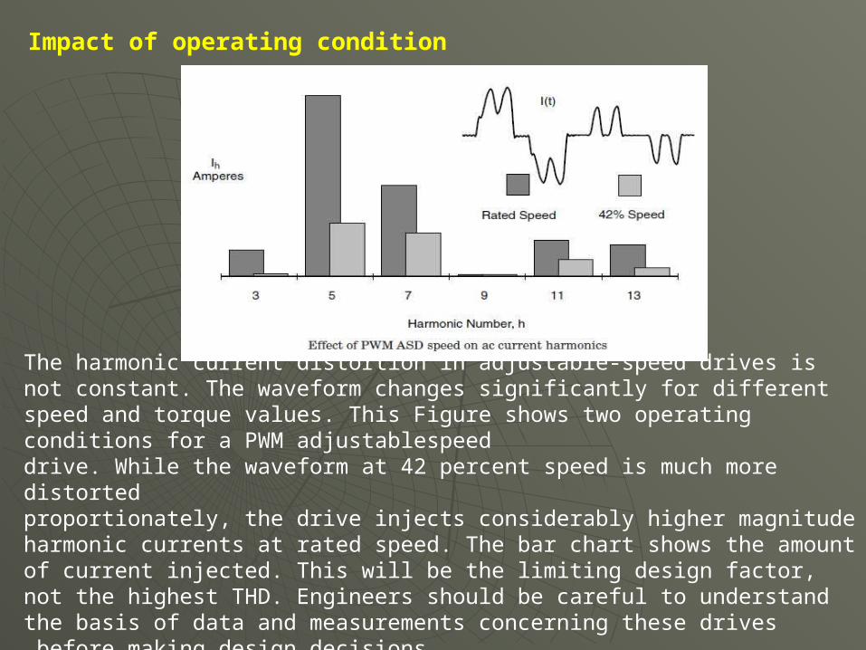
The harmonic current distortion in adjustable-speed drives is not constant. The waveform changes significantly for different speed and torque values. This Figure shows two operating conditions for a PWM adjustablespeeddrive. While the waveform at 42 percent speed is much more distortedproportionately, the drive injects considerably higher magnitude harmonic currents at rated speed. The bar chart shows the amount of current injected. This will be the limiting design factor, not the highest THD. Engineers should be careful to understand the basis of data and measurements concerning these drives before making design decisions

2.2 Arcing devicesThis category includes arc furnaces, arc welders, and discharge-type lighting (fluorescent, sodium vapor, mercury vapor) with magnetic ballasts
the arc is basically a voltage clamp in series with a reactance that limits current to a reasonable value.The voltage-current characteristics of electric arcs are nonlinear.Following arc ignition, the voltage decreases as the arc current increases, limited only by the impedance of the power system. This gives the arc the appearance of having a negative resistance for a portion of its operating cycle such as in fluorescent lighting applications.
The electric arc itself is actually best represented as a source of voltageharmonics. If a probe were to be placed directly across the arc, one would observe a somewhat trapezoidal waveform. Its magnitude is largely a function of the length of the arc. However, the impedance of ballasts or furnace leads acts as a buffer so that the supply voltage is only moderately distorted.
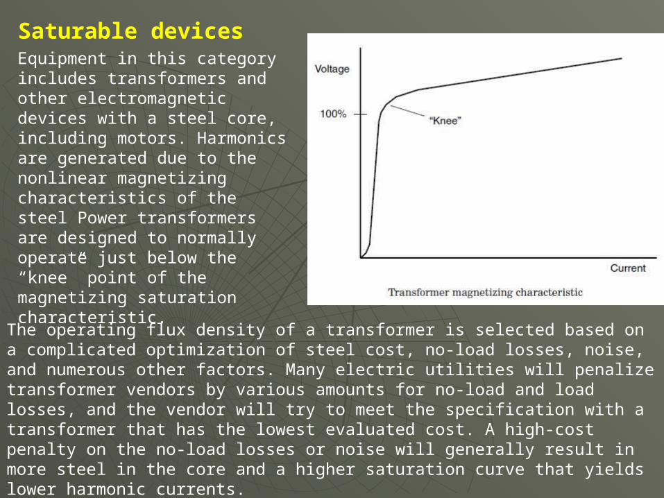
Saturable devices Equipment in this category includes transformers and other electromagnetic devices with a steel core, including motors. Harmonics are generated due to the nonlinear magnetizing characteristics of the steel Power transformers are designed to normally operate just below the “knee” point of the magnetizing saturation characteristic.
The operating flux density of a transformer is selected based on a complicated optimization of steel cost, no-load losses, noise, and numerous other factors. Many electric utilities will penalize transformer vendors by various amounts for no-load and load losses, and the vendor will try to meet the specification with a transformer that has the lowest evaluated cost. A high-cost penalty on the no-load losses or noise will generally result in more steel in the core and a higher saturation curve that yields lower harmonic currents.