wester’s garage ecm pro™ enhanced engine parameters...
TRANSCRIPT
Wester’s Garage ECM-Pro™ Enhanced Engine Parameters
1
Wester’s Garage ECM-Pro™ Enhanced Engine Parameters
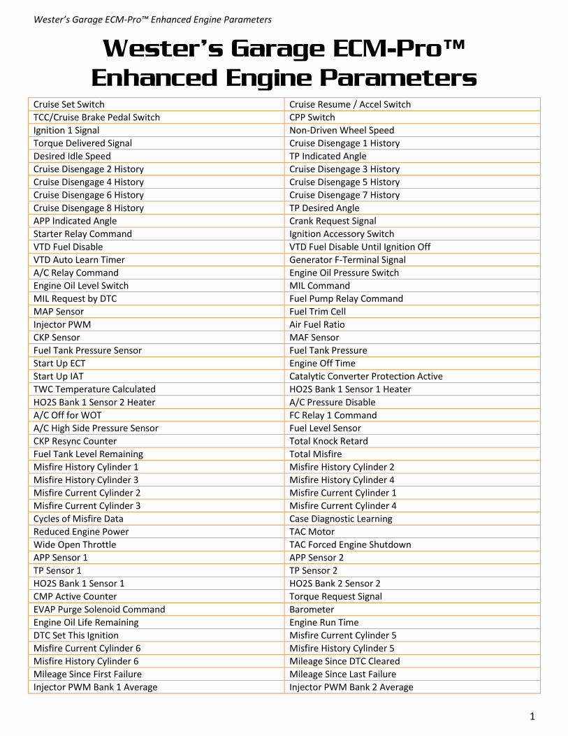
Cruise Set Switch Cruise Resume / Accel Switch
TCC/Cruise Brake Pedal Switch CPP Switch
Ignition 1 Signal Non-Driven Wheel Speed
Torque Delivered Signal Cruise Disengage 1 History
Desired Idle Speed TP Indicated Angle
Cruise Disengage 2 History Cruise Disengage 3 History
Cruise Disengage 4 History Cruise Disengage 5 History
Cruise Disengage 6 History Cruise Disengage 7 History
Cruise Disengage 8 History TP Desired Angle
APP Indicated Angle Crank Request Signal
Starter Relay Command Ignition Accessory Switch
VTD Fuel Disable VTD Fuel Disable Until Ignition Off
VTD Auto Learn Timer Generator F-Terminal Signal
A/C Relay Command Engine Oil Pressure Switch
Engine Oil Level Switch MIL Command
MIL Request by DTC Fuel Pump Relay Command
MAP Sensor Fuel Trim Cell
Injector PWM Air Fuel Ratio
CKP Sensor MAF Sensor
Fuel Tank Pressure Sensor Fuel Tank Pressure
Start Up ECT Engine Off Time
Start Up IAT Catalytic Converter Protection Active
TWC Temperature Calculated HO2S Bank 1 Sensor 1 Heater
HO2S Bank 1 Sensor 2 Heater A/C Pressure Disable
A/C Off for WOT FC Relay 1 Command
A/C High Side Pressure Sensor Fuel Level Sensor
CKP Resync Counter Total Knock Retard
Fuel Tank Level Remaining Total Misfire
Misfire History Cylinder 1 Misfire History Cylinder 2
Misfire History Cylinder 3 Misfire History Cylinder 4
Misfire Current Cylinder 2 Misfire Current Cylinder 1
Misfire Current Cylinder 3 Misfire Current Cylinder 4
Cycles of Misfire Data Case Diagnostic Learning
Reduced Engine Power TAC Motor
Wide Open Throttle TAC Forced Engine Shutdown
APP Sensor 1 APP Sensor 2
TP Sensor 1 TP Sensor 2
HO2S Bank 1 Sensor 1 HO2S Bank 2 Sensor 2
CMP Active Counter Torque Request Signal
EVAP Purge Solenoid Command Barometer
Engine Oil Life Remaining Engine Run Time
DTC Set This Ignition Misfire Current Cylinder 5
Misfire Current Cylinder 6 Misfire History Cylinder 5
Misfire History Cylinder 6 Mileage Since DTC Cleared
Mileage Since First Failure Mileage Since Last Failure
Injector PWM Bank 1 Average Injector PWM Bank 2 Average

Wester’s Garage ECM-Pro™ Enhanced Engine Parameters
2
HO2S Bank 2 Sensor 1 Knock Retard
Misfire Current Cylinder 7 Misfire Current Cylinder 8
Misfire History Cylinder 7 Misfire History Cylinder 8
Warm-Ups without Emission Faults Warm-Ups without Non-Emission Faults
Cruise Inhibit Signal Extended Travel Brake Switch
Decel Fuel Cutoff EVAP Vent Solenoid Command
Fuel Trim Learn Power Enrichment
ECM Reset Loop Status
EVAP Test Result EVAP Test Abort Reason
EVAP Test State HO2S Bank 2 Sensor 1 Heater
HO2S Bank 2 Sensor 2 Heater Engine Idling
A/C Request Low Coolant Level
Cruise Brake Switch TP Sensor
HO2S Bank 1 Sensor 2 Desired Idle Speed
A/C Request Signal A/C Pressure Disable
A/C Off for WOT A/C Relay Command
BPP Circuit Signal HO2S 1 Heater Command
HO2S 2 Heater Command Change Engine Oil Indicator Command
Low Engine Oil Pressure Indicator Command Engine Oil Level Switch
Cold Startup EVAP Vent Solenoid Command
Fuel Volatility RVS Request Signal
Starter Relay Command EC Ignition Relay Command
Ignition Accessory Signal Crank Request Signal
Engine Load Engine Oil Pressure Sensor
MIL Circuit Commanded On Vehicle Speed Circuit Commanded On
Starter Relay Circuit Commanded On Fuel Pump Relay Circuit Commanded On
A/C Relay Circuit Commanded On TP Sensor 1 Learned Minimum
TP Sensor 2 Learned Minimum Engine Off Time
TAC Motor Command CMP Solenoid Circuit Commanded On
Cylinder 2 Ignition Coil Commanded On Cylinder 3 Ignition Coil Commanded On
Cylinder 1 Injector Circuit Commanded On Cylinder 2 Injector Circuit Commanded On
Cylinder 3 Injector Circuit Commanded On Cylinder 4 Injector Circuit Commanded On
Cylinder 5 Injector Circuit Commanded On Cylinder 6 Injector Circuit Commanded On
EVAP Purge Solenoid Circuit Commanded On EVAP Vent Solenoid Circuit Commanded On
FC Relay 1 Circuit Commanded On FC Relay 2 and 3 Circuit Commanded On
CMP Sensor HO2S 1 Heater Circuit Commanded On
HO2S 2 Heater Circuit Commanded On EC Ignition Circuit Commanded On
Generator L-Terminal Circuit Commanded On A/C Disengage 1 History
A/C Disengage 2 History A/C Disengage 3 History
A/C Disengage 4 History A/C Disengage 5 History
A/C Disengage 6 History A/C Disengage 7 History
A/C Disengage 8 History RVS Disable 1 History
RVS Disable 2 History RVS Disable 3 History
RVS Disable 4 History RVS Disable 5 History
RVS Disable 6 History RVS Disable 7 History
RVS Disable 8 History Knock Detected Cylinder 1
Knock Detected Cylinder 2 Knock Detected Cylinder 3
Knock Detected Cylinder 4 Knock Detected Cylinder 5
Knock Detected Cylinder 6 Injector 1 Disabled Due to Misfire
Injector 2 Disabled Due to Misfire Injector 3 Disabled Due to Misfire
Injector 4 Disabled Due to Misfire Injector 5 Disabled Due to Misfire

Wester’s Garage ECM-Pro™ Enhanced Engine Parameters
3
Injector 6 Disabled Due to Misfire IMT Valve Solenoid Circuit Commanded On
IMT Valve Feedback signal IMT Valve Command Open/Closed
IMT Valve Command On/Off IMT Valve Learn Enabled
Start Up ECT Cylinder 7 Injector Circuit Commanded On
Cylinder 8 Injector Circuit Commanded On Current Gear
Knock Detected Cylinder 7 Knock Detected Cylinder 8
Injector 7 Disabled Due to Misfire Injector 8 Disabled Due to Misfire
Cruise Control Active Cruise On/Off Switch
Cruise Set/Coast Switch Cruise Resume/Accel Switch
Starter Relay Command Wait to Start
A/C Relay Command MIL Command
Fuel Pump Command Water in Fuel Sensor
Generator L-Terminal Signal Engine Oil Level Switch
Stop lamp Pedal Switch Coolant Level Switch
PTO Enable PTO Feedback Signal
PTO Engine Shutdown Signal PTO Engage Relay Command
DTC Set this Ignition A/C Low Pressure
A/C High Pressure Recirculation A/C Secondary High Pressure Switch
A/C Request Signal A/C Compressor
Balancing Rate Cylinder 1 Balancing Rate Cylinder 2
Balancing Rate Cylinder 3 Balancing Rate Cylinder 4
Balancing Rate Cylinder 5 Balancing Rate Cylinder 6
Balancing Rate Cylinder 7 Balancing Rate Cylinder 8
Calculated Fuel Rate Main Injection Timing
Misfire Current Cylinder 1 Misfire Current Cylinder 2
Misfire Current Cylinder 3 Misfire Current Cylinder 4
Misfire Current Cylinder 5 Misfire Current Cylinder 6
Misfire Current Cylinder 7 Misfire Current Cylinder 8
Pilot Injector Cylinder 1 Command Pilot Injector Cylinder 2 Command
Pilot Injector Cylinder 3 Command Pilot Injector Cylinder 4 Command
Pilot Injector Cylinder 5 Command Pilot Injector Cylinder 6 Command
Pilot Injector Cylinder 7 Command Pilot Injector Cylinder 8 Command
4WD Signal 4WD Low Signal
5 Volt Reference Circuit 1 Status 5 Volt Reference Circuit 2 Status
Cruise Control Active Cruise On / Off Switch
Cruise Resume / Accel Switch Cruise Set / Coast Switch
Cruise Cancel Switch MIL Command
Engine Oil Temperature Calculated Energy Power Management Inhibit Reason
Generator L-Terminal Command 5 Volt Reference 2 Circuit
5 Volt Reference 1 Circuit ECM Reset
MIL Command PNP Switch
Traction Control Status Catalytic Control Status
Cold Startup EVAP Vent Solenoid Command
ECM Reset Loops Status
Hot Open Loop Deceleration Fuel Cutoff
Power Enrichment Fuel Trim Learn
GEN L-Terminal Signal Command GEN L-Terminal Signal
Reduced Engine Power APP Sensors 1 and 2
TP Sensors 1 and 2 FC Relay 3 Command
FC Relay 2 Command FC Relay 2 and 3 Command
FC Relay 1 Command A/C Compressor Cycling Switch

Wester’s Garage ECM-Pro™ Enhanced Engine Parameters
4
A/C High Side Pressure Switch Ext. Travel BPP Signal
BPP Signal Clutch Start Switch
Skip Shift Lamp Command Skip Shift Solenoid Command
HO2S Bank 2 Sensor 2 Heater Command HO2S Bank 2 Sensor 1 Heater Command
Low Engine Oil Pressure Indicator Command Engine Oil Pressure Switch
Engine Oil Indicator Command EVAP Vent Solenoid Command
Engine Off EVAP Test Conditions Met 4WD Signal
4WD Low Signal PNP Switch
PTO Remote Start Request Signal Catalytic Converter Protection
Fuel Pump Relay 2 Command Fuel Pump Relay Command
Deceleration Fuel Cutoff Hot Open Loop
Power Enrichment Loop Status
Fuel Trim Learn Gen L-Terminal Signal Command
Starter Relay Command Gen L-Terminal Signal Command
Cylinder Deactivation System Command Cylinder Deactivation Performance Test
TP Performance Test MAP Performance Test 2
MAP Performance Test 1 MAF Performance Test
Brake Booster Pressure Sensor Brake Booster Pressure
Engine Oil Pressure Sensor CKP Active Counter
Torque Management Spark Retard KS Active Counter
Vacuum Calculated Air Flow Calculated
Distance Since DTC Cleared Fail Counter
Pass Counter Not Run Counter
Fuel Tank Pressure APP Sensors
TP Sensor 2 TP Sensor 1
APP Sensor 2 APP Sensor 1
Injector PWM Bank 1 Injector PWM Bank 2
VTD Fuel Disable PCM/VCM in VTD Fail Enable
VTD Password Learned CKP Variation Learn Attempts
Fuel Tank Rated Capacity Fuel Level Remaining
TCS Torque Request Signal TCS Torque Delivered Signal
Fuel Sensor Right Tank TWC Mon. Bank 1 Test Count
TWC Mon. Bank 2 Test Count Cooling Fan Motor Commanded
5 Volt Reference 1 5 Volt Reference 2
HO2S Bank 1 Sensor 1 Heater Command HO2S Bank 2 Sensor 1 Heater Command
EC Ignition Relay Feedback Signal Brake Booster Pressure
Deactivation Inhibit TAC Ignition Voltage Deactivation Inhibit TAC System DTC
Deactivation Inhibit APP High Deactivation Inhibit APP Rate High
Deactivation Inhibit Brake Boost Pressure Sensor DTC Deactivation Inhibit Low Brake Booster Vacuum
Deactivation Inhibit MAP Sensor DTC Deactivation Inhibit Manifold Vacuum Low
Deactivation Inhibit Vehicle Speed Sensor DTC Deactivation Inhibit Vehicle Speed Sensor Low with Torque Converter Clutch On
Deactivation Inhibit Engine RPM Deactivation Inhibit Engine Coolant Temperature Sensor DTC
Deactivation Inhibit Engine Coolant Temperature Low Deactivation Inhibit Engine Oil Temperature
Deactivation Inhibit Engine Oil Pressure Sensor DTC Deactivation Inhibit Engine Oil Pressure
Deactivation Inhibit Torque Reduction Deactivation Inhibit Cylinder Deactivation Solenoid DTC
Deactivation Inhibit Oil Aeration Deactivation Inhibit Minimum Time On All Cylinders
Deactivation Inhibit Transmission DLC Override Deactivation Inhibit Transmission Shifting
Deactivation Inhibit Transmission Range Deactivation Inhibit Transmission Gear
Deactivation Inhibit Maximum Deactivation Time Exceeded Deactivation Inhibit Hot Coolant Mode

Wester’s Garage ECM-Pro™ Enhanced Engine Parameters
5
Deactivation Inhibit Piston Protection Deactivation Inhibit TWC Over temperature Protection
Deactivation Inhibit Engine Over temperature Protection Deactivation Inhibit Axle Torque Limiting
ECM Challenge Status VTD Security Info Programmed
VTD Password Learn Enabled VTD Auto Learn Counter
A/C High Side Pressure Short Term Fuel Trim Average
Short Term Fuel Trim Test Average Bank 1 Short Term Fuel Trim Test Average Bank 2
Long Term Fuel Trim Test Average Bank 1 Long Term Fuel Trim Test Average Bank 2
Long Term Fuel Trim Test Average Bank 1 without Purge Long Term Fuel Trim Test Average Bank 2 without Purge
Start Up IAT Fan Speed
Desired Fan Speed Cooling Fan Command
Ignition Off Time Exh. CMP Command
Int. CMP Command CMP Command
HO2S Bank 2 Sensor 2 Heater Command HO2S Bank 1 Sensor 2 Heater Command
Exh. CMP Angle Int. CMP Angle
Desired Exh. CMP Desired Int. CMP
Exh. CMP Variance Int. CMP Variance
Exh. CMP Active Counter Int. CMP Active Counter
Transfer Case Ratio Torque Delivered Signal
Hill Hold Solenoid 1 Hill Hold Solenoid 2
Generator Starter Field Current Starter Generator Speed
Generator Starter Rotor Position SGCM 12 Volt Converter
SGCM Converter Temperature APM Voltage
Desired APM Voltage Hybrid System Voltage
SGCM Internal Temperature SGCM Inverter Temperature
DMCM Coolant Temperature MAP Sensor
Intake Manifold Pressure Startup Intake Air Temperature
Distance with Cylinders Deactivated Distance with Cylinders Activated
Exhaust Pressure Torque Request Inhibit - Fuel
Torque Request Inhibit - Spark Torque Request Inhibit - TAC
Torque Request Inhibit - Minimum Torque Torque Request Inhibit - TAC Limit
Torque Request Inhibit - Spark Advance Torque Request Inhibit - Minimum Idle Inhibit
Transfer Case OSS TB Idle Airflow Compensation
Engine Auto Stop Times Engine Auto Start Times
DFCO Active Time Desired Starter Gen Torque
Calculated Starter Generator Torque ECM Des. Contactor Position
SGCM Des. Contactor Position Economy Lamp Command
Hood Open Indicator Command Hill Hold Indicator Command
Starter Generator Belt Slip Starter Generator Speed
Hybrid Battery SoC Desired Hybrid Battery SoC
Hybrid Battery Voltage Hybrid Battery Current
Hybrid Battery Average Cell Temperature Hybrid Battery Max Cell Temperature
Hybrid Battery Min Cell Temperature Hybrid Battery Power Available
Brake Pressure Sensor Engine Coolant Circulation Pump Relay Command
A/C Mode Request Signal Engine Torque Actual
Axle Torque Commanded Axle Torque Actual
Dry Axle Torque Request Engine Torque Commanded
Auxiliary Transmission Fluid Pump Relay Auxiliary Transmission Fluid Pump Command
Hybrid System Voltage Calculated Hybrid Battery Voltage
Hybrid Battery Low Current Sensor Hybrid Battery High Current Sensor
Hybrid Battery Low Current Sensor Hybrid Battery High Current Sensor
Hybrid Battery Mod 1 Temperature Hybrid Battery Mod 1 Temperature Sensor

Wester’s Garage ECM-Pro™ Enhanced Engine Parameters
6
Hybrid Battery Mod 2 Temperature Hybrid Battery Mod 2 Temperature Sensor
Hybrid Battery Mod 3 Temperature Hybrid Battery Mod 3 Temperature Sensor
Hybrid Battery Mod 4 Temperature Hybrid Battery Mod 4 Temperature Sensor
Hybrid Battery Mod 5 Temperature Sensor Hybrid Battery Mod 5 Temperature
Hybrid Battery Mod 6 Temperature Sensor Hybrid Battery 1
Hybrid Battery 2 Hybrid Battery 3
Hybrid Battery Pack Fan Sensor Hybrid Battery Pack Fan Commanded
Calculated Hybrid Battery Resistance 12V Battery Estimated Temperature
Cylinder 4 Ignition Coil Commanded On Cylinder 5 Ignition Coil Commanded On
Cylinder 6 Ignition Coil Commanded On Cylinder 1 Ignition Coil Commanded On
Cylinder 1 Ignition Coil Short to Ground Test Status Cylinder 1 Ignition Coil Open Circuit Test Status
Cylinder 1 Ignition Coil Short to Power Test Status Cylinder 2 Ignition Coil Short to Ground Test Status
Cylinder 2 Ignition Coil Open Circuit Test Status Cylinder 2 Ignition Coil Short to Power Test Status
Cylinder 3 Ignition Coil Short to Ground Test Status Cylinder 3 Ignition Coil Open Circuit Test Status
Cylinder 3 Ignition Coil Short to Power Test Status Cylinder 4 Ignition Coil Short to Ground Test Status
Cylinder 4 Ignition Coil Open Circuit Test Status Cylinder 4 Ignition Coil Short to Power Test Status
Cylinder 5 Ignition Coil Short to Ground Test Status Cylinder 5 Ignition Coil Open Circuit Test Status
Cylinder 5 Ignition Coil Short to Power Test Status Cylinder 6 Ignition Coil Short to Ground Test Status
Cylinder 6 Ignition Coil Open Circuit Test Status Cylinder 6 Ignition Coil Short to Power Test Status
Cylinder 7 Ignition Coil Commanded On Cylinder 8 Ignition Coil Commanded On
Cylinder 7 Ignition Coil Short to Ground Test Status Cylinder 7 Ignition Coil Open Circuit Test Status
Cylinder 7 Ignition Coil Short to Power Test Status Cylinder 8 Ignition Coil Short to Ground Test Status
Cylinder 8 Ignition Coil Open Circuit Test Status Cylinder 8 Ignition Coil Short to Power Test Status
Cylinder 1 Injector Circuit Short to Ground Test Status Cylinder 1 Injector Circuit Open Circuit Test Status
Cylinder 2 Injector Circuit Short to Ground Test Status Cylinder 2 Injector Circuit Open Circuit Test Status
Cylinder 2 Injector Circuit Short to Power Test Status Cylinder 1 Injector Circuit Short to Power Test Status
Cylinder 3 Injector Circuit Short to Ground Test Status Cylinder 3 Injector Circuit Open Circuit Test Status
Cylinder 3 Injector Circuit Short to Power Test Status Cylinder 4 Injector Circuit Short to Ground Test Status
Cylinder 4 Injector Circuit Open Circuit Test Status Cylinder 4 Injector Circuit Short to Power Test Status
Cylinder 5 Injector Circuit Short to Ground Test Status Cylinder 5 Injector Circuit Open Circuit Test Status
Cylinder 5 Injector Circuit Short to Power Test Status Cylinder 6 Injector Circuit Short to Ground Test Status
Cylinder 6 Injector Circuit Open Circuit Test Status Cylinder 6 Injector Circuit Short to Power Test Status
Cylinder 7 Injector Circuit Short to Ground Test Status Cylinder 7 Injector Circuit Open Circuit Test Status
Cylinder 7 Injector Circuit Short to Power Test Status Cylinder 8 Injector Circuit Short to Ground Test Status
Cylinder 8 Injector Circuit Open Circuit Test Status Cylinder 8 Injector Circuit Short to Power Test Status
HO2S 1 Heater Circuit Short to Ground Test Status HO2S 1 Heater Circuit Open Circuit Test Status
HO2S 1 Heater Circuit Short to Power Test Status HO2S 2 Heater Circuit Short to Ground Test Status
HO2S 2 Heater Circuit Open Circuit Test Status HO2S 2 Heater Circuit Short to Power Test Status
MIL Circuit Short to Ground Test Status MIL Circuit Open Circuit Test Status
MIL Circuit Short to Power Test Status IMT Valve Solenoid Circuit Short to Ground Test Status
IMT Valve Solenoid Circuit Open Circuit Test Status IMT Valve Solenoid Circuit Short to Power Test Status
Generator L-Terminal Circuit Short to Ground Test Status Generator L-Terminal Circuit Open Circuit Test Status
Generator L-Terminal Circuit Short to Power Test Status EC Ignition Circuit Short to Ground Test Status
EC Ignition Circuit Open Circuit Test Status EC Ignition Circuit Short to Power Test Status
FC Relay 2 and 3 Circuit Short to Ground Test Status FC Relay 2 and 3 Circuit Open Circuit Test Status
FC Relay 2 and 3 Circuit Short to Power Test Status FC Relay 1 Circuit Short to Ground Test Status
FC Relay 1 Circuit Open Circuit Test Status FC Relay 1 Circuit Short to Power Test Status
EVAP Vent Solenoid Circuit Short to Ground Test Status EVAP Vent Solenoid Circuit Open Circuit Test Status
EVAP Vent Solenoid Circuit Short to Power Test Status EVAP Purge Solenoid Circuit Short to Ground Test Status
EVAP Purge Solenoid Circuit Open Circuit Test Status EVAP Purge Solenoid Circuit Short to Power Test Status
CMP Solenoid Circuit Short to Ground Test Status CMP Solenoid Circuit Open Circuit Test Status

Wester’s Garage ECM-Pro™ Enhanced Engine Parameters
7
CMP Solenoid Circuit Short to Power Test Status A/C Relay Circuit Short to Ground Test Status
A/C Relay Circuit Open Circuit Test Status A/C Relay Circuit Short to Power Test Status
Fuel Pump Relay Circuit Short to Ground Test Status Fuel Pump Relay Circuit Open Circuit Test Status
Fuel Pump Relay Circuit Short to Power Test Status Starter Relay Circuit Short to Ground Test Status
Starter Relay Circuit Open Circuit Test Status Starter Relay Circuit Short to Power Test Status
Vehicle Speed Circuit Short to Ground Test Status Vehicle Speed Circuit Open Circuit Test Status
Vehicle Speed Circuit Short to Power Test Status Cruise Control Active
Transmission Fluid Temperature Output Shaft Speed
TCC / Cruise Brake Pedal Switch 5 Volt Reference Circuit 3 Status
Engine Oil Life Remaining IAT Sensor 2
Injector 2 Command Injector 3 Command
Injector 4 Command Total Fuel Trim Average
Calculated ECT - Closed Loop Fuel Control Calculated ECT - Thermostat Diagnosis
HO2S 1 Sensing Element HO2S 2 Sensing Element
Exh. CMP Angle Int. CMP Angle
Desired Exh. CMP Exh. CMP Variance
Int. CMP Variance Desired Int. CMP
FRP Regulator Command Post Inj. Cylinder 1 Command
Post Inj. Cylinder 2 Command Post Inj. Cylinder 3 Command
Post Inj. Cylinder 4 Command TCM Requested Torque
Boost Pressure Boost Pressure Sensor
Cruise Release Clutch/TCC Pedal Switch Cruise Control Active
A/C Request Signal MIL Command
A/C Relay Command EVAP Vent Solenoid Command
Fuel Pump Relay Command Generator L-Terminal Signal
FC Relay 1 Command Loop Status
Power Enrichment VTD Fuel Disable
VTD Auto Learn Timer Ignition Voltage
Manifold Absolute Pressure Sensor TP Sensor
A/C High Side Pressure A/C High Side Pressure Sensor
HO2 Bank 1 Sensor 1 HO2 Bank 1 Sensor 2
Generator F-Terminal Fuel Tank Pressure Sensor
Fuel Tank Pressure Fuel Level
CKP Active Counter CMP Active Counter
Medium Resolution Re-Sync Counter CMP Re-Sync Counter
EVAP Purge Solenoid Command IAC Position
Fuel Trim Cell Desired Idle Speed
Injector 1 Command Injector 2 Command
Injector 3 Command Injector 4 Command
Barometer Air Fuel Ratio
Engine Oil Life Remaining Engine Run Time
Number of DTCs TWC Temperature Calculated
Knock Retard Air Flow Calculated
Misfire History Cylinder 1 Misfire History Cylinder 2
Misfire History Cylinder 3 Misfire History Cylinder 4
Misfire Current Cylinder 2 Misfire Current Cylinder 1
Misfire Current Cylinder 3 Misfire Current Cylinder 4
Fuel Trim Index Misfire Test Failures Since 1st Fail
EVAP Test Abort Reason EVAP Test State
Start Up IAT Cruise On/Off Switch
A/C Request Signal Cruise Resume/Accelerate Switch

Wester’s Garage ECM-Pro™ Enhanced Engine Parameters
8
Cruise Set/Coast Switch Clutch Pedal Switch
Engine Shutoff Solenoid Glow Plug Relay Command
Fuel Pump Relay Command MIL Command
Service Throttle Sppn Lamp Command A/C Relay Command
Fuel Temperature APP Indicated Angle
Fuel Pump Relay Feedback Signal APP Sensor 2
APP Sensor 3 Glow Plug Feedback Signal
Injection Pump Cam Reference Signal Missed Boost Pressure Sensor
Start Up ECT Desired Injection Pump Timing
Injection Pump Timing Signal Calculated Fuel Rate
TDC Offset CKP Sensor Pulses Missed
PCM / VCM in VTD Fail Enable VTD Fuel Disable Until Ignition Off
VTD Auto Learn Timer VTD Fuel Disable
APP Sensor 1 Misfire Current Cylinder 5
Misfire Current Cylinder 6 Misfire Current Cylinder 7
Misfire Current Cylinder 8 Misfire History Cylinder 5
Misfire History Cylinder 6 Misfire History Cylinder 7
Misfire History Cylinder 8 Cruise Control Disengage 1 History
Cruise Control Disengage 2 History Cruise Control Disengage 3 History
Cruise Control Disengage 4 History Cruise Control Disengage 5 History
Cruise Control Disengage 6 History Cruise Control Disengage 7 History
Cruise Control Disengage 8 History PCM Reset
A/C Relay Command GEN L-Terminal Signal Command
A/C Clutch Feedback Signal A/C Request Signal
EVAP Vent Solenoid Command TCC Brake Pedal Switch
VTD Fuel Disable TCC Enable Solenoid Command
TCC PWM Solenoid Command Fuel Trim Learn
Cold Startup 4WD Low Signal
4WD Signal HO2 Bank 2 Sensor 1
HO2 Bank 2 Sensor 2 Desired EGR Position
Engine Oil Life Remaining EGR Closed Valve Pintle Position
Short Term Fuel Trim Average Bank 1 Long Term Fuel Trim Average Bank 1
Short Term Fuel Trim Average Bank 2 Warm-Ups without Emission Faults
Warm-Ups without Non-Emission Faults Mileage Since DTC Cleared
Long Term Fuel Trim Average Bank 2 Transmission Switch
Cycles of Misfire Data EGR Position Sensor
EGR Solenoid Command Torque Delivered Signal
Start Up ECT Engine Load
Engine Oil Level Fuel Composition Sensor
Extended Travel Brake Pedal Switch Engine Oil Level Switch
Engine Oil Pressure Switch Crank Request Signal
TCC Brake Pedal Switch Engine Oil Pressure
FC Relay 2 Command Air Pump Relay Command
A/C Relay CKT Open Short to Ground Air Pump Relay CKT Open Short to Ground
EVAP Purge CKT Open Short to Ground Module Driver Overvoltage
FC 1 Relay CKT Open Short to Ground FC 2 Relay CKT Open Short to Ground
EVAP Vent CKT Open Short to Ground Starter Relay Command
TCC Brake Pedal Switch Cruise Inhibit Signal Command
Loop Status Fuel Trim Learn
Desired Idle Speed EGR Position Sensor
Fuel Tank Rated Capacity CMP - Low to High

Wester’s Garage ECM-Pro™ Enhanced Engine Parameters
9
MIL Command Air Pump Relay Command
Cruise Inhibit Signal Command DTC Set This Ignition
Barometer Injector PWM Bank 2 Average
Fuel Tank Pressure Sensor Desired IAC Position
EVAP Test Result CMP Retard
CMP - High to Low Desired IAC Airflow
A/C Relay Command Air Solenoid Command
Desired EGR Position Injector PWM Bank 1 Average
Non-Driven Wheel Speed Odometer
Knock Retard MAF Sensor
VTD Password Fuel Level
MIL Command Air Solenoid Command
Air Pump Relay Command Cruise Inhibit Signal Command
Powertrain Induced Chassis Pitch Command Starter Relay Command
Fuel Pump Relay Command A/C Relay Command
EVAP Vent Solenoid Command FC Relay 1 Command
FC Relay 2 and 3 Command CMP Senor
24X Crank Sensor CKP Sensor Status
CKP Sensor Signal Present TFP Switch
PCM Reset Fuel Pump Relay Command
MIL Command Decel Fuel Cutoff
VTD Fuel Disable Ignition Mode
EVAP Vent Solenoid Command Engine Oil Level Switch
GEN L-Terminal Signal Command CMP Sensor Signal Present
3X Crank Sensor MAF Sensor
24X Crank Sensor Low Speed Fan
High Speed Fan A/C Request
A/C Off for WOT A/C Pressure Disable
Non Volatile Memory A/C Relay Command
Low Coolant Level Brake Switch
Coolant Fan Relay Command EVAP Purge Solenoid
DTC Set This Ignition Clutch Pedal Switch
Extended Travel Brake Pedal Switch Reverse Inhibit Solenoid Command
Traction Control Status Cruise Release Brake Pedal Switch
Powertrain Induced Chassis Pitch Command TCC Enable Solenoid Command
Skip Shift Lamp Command Skip Shift Solenoid Command
Reduced Engine Power Engine Oil Level Switch
Air Solenoid Command Cruise Control Active
APP Average Fuel Tank Level Remaining
MIL Command Reduced Engine Power
TCC Enable Solenoid Command Cruise Control Active
TCC PWM Solenoid Command DTC Set This Ignition
PCM Reset 4WD Signal
4WD Low Signal A/C Request Signal
A/C Clutch Feedback Signal A/C Secondary High Pressure Switch
Generator L Terminal Engine Coolant Level
Transmission Switch A Transmission Switch B
Transmission Switch C Transmission Switch P
FC Relay Stepper Cruise
PC Enabled 1-2 Solenoid
2-3 Solenoid Manifold Absolute Pressure

Wester’s Garage ECM-Pro™ Enhanced Engine Parameters
10
Fuel Level Sensor ESC Noise Channel
Barometric Pressure Sensor ESC Active Counter
Purge Learned Memory Low Octane Fuel Spark Modifier
MAF History Display EGR Trip Samples
Decel EWMA Misfiring Cylinder (Primary)
Misfiring Cylinder (Secondary) Total Misfire
EGR Delta MAP Circulation PRNDL A
PRNDL B A/C Status
Set Switch PRNDL C
High Electrical Load Resume Switch
PRNDL P A/C Clutch
Power Steering Pressure Switch Park Neutral Switch
Cruise Brake Switch Extended Travel Brake
Fast Idle Setting PNP
EGR Vent Solenoid 1-2 Solenoid
2-3 Solenoid STS Lamp
Transmission Hot Mode TCC Release Press
Shift Mode Switch EVAP Vacuum Switch
Traction Control Traction Control
TFP Switch A TFP Switch B
TFP Switch C A/C Status
A/C Request Engine Hot Lamp
Low Oil Lamp Cruise Requested
Generator Lamp Change Oil Lamp
Park Neutral Position Fuel Pump Speed
TCC Brake Switch HO2 Bank 1 Sensor 1
HO2 Bank 2 Sensor 1 Shift Solenoid A
Shift Solenoid B Fuel Trim Learn
Shift Solenoid C Rich/Lean Status
Traction Control EVAP Vacuum Switch
EVAP Vacuum Switch TWC Protection
Pass Key Fuel Hot Open Loop
FC Relay 2 and 3 FC Relay 1
Power Enrichment Knock Signal Present
RPM High Resolution Signal Abuse Management
EGR Loop Status Skip Shift Solenoid
Ignition Bypass Reverse Inhibit
TCC Duty Cycle TCC Enable
Fuel Trim Diag. Inhibit Evap Vacuum Switch
Injector Fault FC Relay 1
FC Relay 2 and 3 Air Pump
Engine Oil Level A/C Clutch
Throttle at Idle Cold Start Up
Loop Status TCC Enable Shorted
TCC Duty Cycle Shorted Driver 1 Status
CAM Pulse Park Neutral Switch
Shift Mode A/C High Pressure Switch
Oil Life Reset Engine Oil Pressure
Knock Too Long Ignition 1 Status
1-2 Sol Shorted to Volts 2-3 Sol Shorted to Volts
3-2 Downshift Sol Shorted 3-2 Downshift Sol Open

Wester’s Garage ECM-Pro™ Enhanced Engine Parameters
11
2-3 Sol Open/Short to GND 1-2 Sol Open/Short to GND
Fan Control Relay 2 & 3 TCC Enable
TCC Enable Short to GND TWC Diagnostics
TCC DC Short to GND PCM Ride Control
A/C Relay PRND A Input
PRND B Input PRND C Input
TR Switch Park/Neut TR Switch Reverse
TR Switch Park/Neut IC Circuit Cylinder 1
IC Circuit Cylinder 2 IC Circuit Cylinder 3
IC Circuit Cylinder 4 IC Circuit Cylinder 5
IC Circuit Cylinder 6 IC Circuit Cylinder 7
IC Circuit Cylinder 8 APP Sensor 1 Out-of-Range
APP Sensor 2 Out-of-Range APP Sensor 3 Out-of-Range
TP Sensor 1 Out-of-Range TP Sensor 2 Out-of-Range
TAC/PCM Communication Cruise Switch
TP Sensors Disagree APP Sensors 1 and 2 Disagree
APP Sensors 1 and 3 Disagree APP Sensors 2 and 3 Disagree
Cruise Set/Coast Cruise Resume/Accel
Stop Lamp Switch Passkey Starter
IC Mode Output Driver 1 Display
MIL Driver Vehicle Speed Output Signal
Tachometer Driver Delivered Torque Driver
Evap Purge Sol Driver Driver 1 Ground
Output Driver 2 Display PCM Ride Control Driver
A/C Relay Driver Cruise Enable Driver
Shift Sol 1 Driver Shift Sol 2 Driver
TCC Solenoid Driver Driver 2 Ground
Output Driver 1 Display MIL Driver
Vehicle Speed Output Signal Tachometer Driver
Delivered Torque Driver Evap Purge Sol Driver
Driver 1 Ground Output Driver 2 Display
PCM Ride Control Driver A/C Relay Driver
Cruise Enable Driver Shift Sol 1 Driver
Shift Sol 2 Driver TCC Solenoid Driver
Driver 2 Ground Engine Oil Level
Injector 1 Fault Injector 2 Fault
Injector 3 Fault Injector 4 Fault
Injector 5 Fault Injector 6 Fault
Injector 7 Fault Injector 8 Fault
VTD Fuel Disable IPC Fuel Disable
VTD Password Auto Learn Timer
VTD Password Learn Mode Rich to Lean Status Bn2 Sen 1
Rich to Lean Status Bn1 Sen 1 Rich to Lean Status Bn1 Sen 2
Rich to Lean Status Bn1 Sen 3 Fuel Trim Learn
Passkey Fuel Passkey Input
Throttle at Idle Fuel Pump Voltage Feedback A/D
Brake Booster Vacuum Brake Booster Vacuum Sensor
Desired Torque Level A/C Lowside Temperature
A/C Highside Temperature Engine Oil Pressure
Outside Air Temp # of 4X Ref Pulses Between CAM Counter
Ignition 1 Voltage Ignition Voltage to ECM Side

Wester’s Garage ECM-Pro™ Enhanced Engine Parameters
12
Lift Pump Volts Trans Detent Relay (Auto Trans)
Supercharged Boost Current IAC Memory
IAC Motor Position Calculated A/C Load
Ignition Cycle Counter Bank 2 O2 Crossover Counts
Bank 1 O2 Crossover Counts Passkey 2 Input
Ref Low Voltage EGR Pintle Position Error
Service Spark Retard O2 Heater Time Activity Bank 1Sensor 1
O2 Heater Time Activity Bank 1Sensor 2 O2 Heater Time Activity Bank 1Sensor 3
O2 Heater Time Activity Bank 2 Sensor 1 O2 Response Lean/Rich Transitions Time Bank 1 Sensor 1
O2 Response Lean/Rich Switches Bank 1 Sensor 1 Catalyst Monitor EWMA Sample Counter Bank 1
O2 Response Lean/Rich Transitions Time Bank 1 Sensor 2 Diesel Fuel Injection Pump Solenoid Closure Time
RPM (Fine Resolution) RPM Low Resolution Signal
Cylinder Mode Misfire Index Misfire Cycle Delay Counter
02 Lean/Rich Transitions O2 Lean/Rich Average Time
O2 Rich/Lean Transitions O2 Rich/Lean Average Time
O2 # of Rich/Lean to Lean/Rich Transitions Bank 1 Sensor 1 O2 Response Lean/Rich Switches Bank 1 Sensor 2
O2 Response Rich/Lean Transitions Time Bank 1 Sensor 2 O2 Response Lean/Rich Transitions Time Bank 1 Sensor 2
O2 Response Rich/Lean Switches Bank 2 Sensor 1 O2 Response Lean/Rich Switches Bank 2 Sensor 1
O2 Response Rich/Lean Transitions Time Bank 2 Sensor 1 O2 Response Lean/Rich Transitions Time Bank 2 Sensor 1
O2 Response Rich/Lean Switches Bank 1 Sensor 1 O2 Response Rich/Lean Transition Time Bank 1 Sensor 1
Misfire Test Passes Since 1st Fail 3X Engine Speed Activity
Baro Pressure 18X Crank Sensor
Knock Retard Knock Counter
Crankshaft Position Sensor Low Resolution Angle Crankshaft Position Sensor Engine Speed
Evap Tank Vacuum Filtered Enhanced EVAP Fault History
HO2S Sensor 1 Bank 1 HO2 Sensor 2 Bank 1
HO2S Sensor 3 Bank 1 HO2S Sensor 1 Bank 2
Electronic Throttle Control Pedal Position Electronic Throttle Control Pedal Position Sensor 1 Angle
Electronic Throttle Control Pedal Position Sensor 2 Angle Electronic Throttle Control Pedal Position Sensor 3 Angle
Electronic Throttle Control Throttle Position Sensor 1 Angle Electronic Throttle Control Throttle Position Sensor 2 Angle
Electronic Throttle Control Throttle Position Sensor 2 Raw Electronic Throttle Control Throttle Position Sensor 1 Raw
Electronic Throttle Control Pedal Position Sensor 3 Raw Electronic Throttle Control Pedal Position Sensor 2 Raw
Electronic Throttle Control Pedal Position Sensor 1 Raw Odometer
Injector PWM Bank 1 Injector PWM Bank 2
Cylinder Air # of EGR Adaptive Learn Matrix Cells Out of Range Low
Desired MAF/EGR Flow Percent Desired Throttle Position
Percent Pedal Rotation Current Octane Level
TAC Module Calibration ID Byte 1 TAC Module Calibration ID Byte 2
TAC Module Calibration ID Byte 3 TAC Module Calibration ID Byte 4
Fuel Tank Level Remaining A/C Evap Temp
ESC Minimum Learned Noise Voltage Traction Control Delivered Torque (if equipped)
Start Up Coolant Temp Engine Speed at Misfire
Engine Load at Misfire Engine Coolant Temperature at Misfire
Forced Motor Commanded Current Speed Ratio
Speed Ratio Loop Status
EVAP Vent Solenoid Clutch Pedal Switch
CL Since Restart Fuel Trim Enable
Rich/Lean Bank 2 TCC Brake Switch
Rich/Lean Bank 1 TR Switch C
TR Switch B TR Switch A
Post HO2S Pre HO2S

Wester’s Garage ECM-Pro™ Enhanced Engine Parameters
13
Injector Fault This Ignition Valid Ref Pulse Occurred
Starter Enable Low Oil Lamp
Spark Control Ignition Crank
Reference Pulse Occurred Injector F Fault Cylinder #5
Injector G Fault Cylinder #4 EVAP Canister Purge
TCC Enable Injector H Fault Cylinder #3
Lift Pump System DTC Set This Ignition
Ignition 1 On Ignition 1 Low
Ignition 1 High Brake Switch
Vacuum Test at Power up 4WD
4WD Low Weak Vacuum Test
1-4 Shift Solenoid Small Leak Test
Purge Leak Test Cruise Requested
A/C Request A/C Relay
A/C Evaporator Switch A/C Secondary High Pressure Switch
Auto Recirculation Mode Rich/Lean Status Bank 2
VTD Fuel Disable VTD Fuel Disable Until Ignition Off
VTD Auto Learn Timer PCM/VCM in VTD Fail Enable
Engine Drag Control Status ABS Drag Event
1-2 Solenoid Open/Short to GND 2-3 Solenoid Open/Short to GND
1-2 Solenoid Open/Short to Ground 2-3 Solenoid Open/Short to Ground
3-2 Downshift Solenoid Open TCC Enable Short to Volts
TCC Duty Cycle Short to Volts PRND A Input
PRND B Input PRND C Input
PRND P Input APP Sensor 2 and APP Sensor 3 Disagree
APP Sensor 1 and APP Sensor 3 Disagree APP Sensor 1 and APP Sensor 2 Disagree
TP Sensors Disagree Injector Circuit Status Cylinder #1
Injector Circuit Status Cylinder #1 Injector Circuit Status Cylinder #1
Injector Circuit Status Cylinder #2 Injector Circuit Status Cylinder #2
Injector Circuit Status Cylinder #2 Injector Circuit Status Cylinder #3
Injector Circuit Status Cylinder #3 Injector Circuit Status Cylinder #3
Injector Circuit Status Cylinder #4 Injector Circuit Status Cylinder #4
Injector Circuit Status Cylinder #4 Injector Circuit Status Cylinder #5
Injector Circuit Status Cylinder #5 Injector Circuit Status Cylinder #5
Injector Circuit Status Cylinder #6 Injector Circuit Status Cylinder #6
Injector Circuit Status Cylinder #6 VTD Password Learn Mode
VTD Fuel Disable Mass Air Flow Sensor 1
Throttle Position Sensor Wastegate Solenoid
Calculated Vacuum TPS Learned Correction Factor
Fuel Injection Pump Injection Angle (Diesel) Cylinder Mode Misfire Index Level (1st Peak)
Revolution Mode Misfire Index (Balance Time) Wheel Acceleration Accel/Decel
Abnormal/Misfire Test Ratio Total Misfire Per Test Special
# Of Failed Catalyst Misfire Tests Out of Last 16 # Of Failed Catalyst Mis Tests Out of Last 16 Since Code Clear
# Of Failed Emission Misfire Tests Out of Last 16 # Of Failed Emission Misfire Tests Out of Last 16 Since Code Clear
Revolution Mode Misfire Index Level O2 Response Rich to Lean Average Time B2 S1
Spark EVAP Tank Vacuum Decay Slope
EVAP Tank Vacuum Pressure Slope TAC Module S/W Level
TAC Module Calibration ID Fuel Level
Start Up Intake Air Temperature VTD Auto Learn Counter

Wester’s Garage ECM-Pro™ Enhanced Engine Parameters
14
VTD Auto Learn Timer VTD Seed and Key Timer
Vehicle Security Status - Fuel Continued Vehicle Security Status - Learning Enabled
Case Attempts to Learn This Ignition Crank Pulse Count Error Leached
Sum Out of Range Opposing Factor out Of Range
Factor Out of Range Test in Progress
Error Learned this Ignition Reference Period
Knock Sensor Knock Retard
MAF Idle Diag No EGR MAF Idle Diag Full EGR
Largest Positive MAF Error Diag Lowest EGR Pressure Diag
EGR Pressure Delta # of EGR Cells Out of Range High
EGR Adaptive Learn Matrix Cell Number EVAP Service Bay Test Minimum Throttle Position
EVAP Service Bay Test Maximum Throttle Position Catalyst Monitor Non-Volatile Mode Word # 2 - Code P0420 Test Initiation Condition Test
Catalyst Monitor Non-Volatile Mode Word # 2 - Code P0420 Test Enable
Catalyst Monitor Non-Volatile Mode Word # 2 - 1 Stage 1 Has Begun
Catalyst Monitor Non-Volatile Mode Word # 2 - 1 Stage 2 Has Begun
Catalyst Monitor Non-Volatile Mode Word # 2 - 1 At Least 1 Test For P0420 Has Completed
Catalyst Monitor Non-Volatile Mode Word # 2 - 1 At Least 1 More Test
Catalyst Monitor Non-Volatile Mode Word # 2 - 1 P0420 Warm-Up Requirements Are Met
Catalyst Monitor Non-Volatile Mode Word # 2 - 1 A Pcode Related to the Catalyst System is Set
Number of New Catalyst Monitor Test Completed
Intake Air Temperature Sensor Voltage Desired Torque (Brake to PCM)
Delivered Torque (Eng. to Trans Input) Fuel Level Sensor Right Tank
Calculated Engine Coolant Temperature Knock/Octane Adjustment Factor
Number of Catalyst Test - Bank 1 Catalyst Test Time Difference EWMA
Catalyst Test Fail Threshold Last TAP
Engine RPM/MPH Ratio TCC Mode
4WD Lamp Shorted 4WD Lamp Open
Slip Adapt Mode Park Switch
Front Axle Requested Front Axle Switch
Transfer Case Lock Commanded Mode Indicator
Encoder Gear Position Mode Switch Selected
ATC Slip Speed Slip Adapt PWM
Last Adapt Highest PWM TP Sensor
Front Propshaft Speed Rear Propshaft Speed
Software ID Ignition 3
GM Part Number Neutral Indicator Light
4WD High Indicator Light 4WD Low Indicator Light
2WD High Indicator Light Auto 4WD Indicator Light
Service 4WD Lamp Encoder Circuit A
Encoder Circuit B Encoder Circuit C
Encoder Circuit P TFP Switch C
Generator L Terminal TFP Switch B
Brake Switch TFP Switch A
Crank Request Cruise Release Switch
Engine Shutoff Solenoid EVAP Vacuum Switch
Low Oil Lamp Air Pump Relay
Auxiliary Fan Air Pump Relay
Low Oil Lamp FC Relay 1
Tow/Haul Mode Trailer Mode
Glow Plug System Type Column Lock Fuel Disable - BCM DTC

Wester’s Garage ECM-Pro™ Enhanced Engine Parameters
15
Column Lock Fuel Disable - ABS DTC Column Lock Fuel Disable - PCM BCM Communication
Clutch Anticipate Switch A/C Relay
Starter Enable Relay TCC Enable Solenoid
Air Pump Relay FC Relay 1
FC Relay 2 and 3 1-2 Solenoid
2-3 Solenoid Cruise Inhibited
GEN Lamp EVAP Vent Solenoid
MIL Low Oil Lamp
Engine Hot Lamp EVAP Purge Solenoid
3-2 Solenoid Open/Short to Ground EVAP Test Inhibited
Fuel Slosh Detected 3-2 Solenoid Short to Volts
2nd Gear Start Shift Mode
Air Active Test Air Injection Air Active Test Passed
Air Active Test Inhibited Air Passive Test Passed
Air Passive Test 1 Passed Air Passive Test 2 Failed
Air Passive Test Inhibited Air Passive Test Progress
TFP Switch A Extended Travel Brake
PSP Switch CKP Sensor Status
HVAC in Recirculation Mode A/C Secondary High Pressure Switch
A/C Compressor Cycling Switch EGR Circuit Status
Low Coolant Level 1-2 Solenoid Short to Volts
2-3 Solenoid Short to Volts TCC Duty Cycle Short to Voltage
Tachometer Count History TCS Circuit History
TCS Circuit Status Cylinder#1 Injector Count Status
Cylinder#2 Injector Count Status Cylinder#3 Injector Count Status
Cylinder#4 Injector Count Status 1-2 Solenoid Open/Short to Ground
2-3 Solenoid Open/Short to Ground TCC Duty Cycle Open/Short to Ground
Cylinder#5 Injector Count Status TCC Solenoid
TCC Duty Cycle Open Short to Ground Cylinder#6 Injector Count Status
MIL Cruise Inhibited
1-2 Solenoid 1-2 Solenoid Open/Short to Ground
2-3 Solenoid Open/Short to Ground 2-3 Solenoid
EVAP Vent Solenoid Driver TCC Duty Cycle Short to Volts
Output Driver 1 Shorted TCC Enable Short to Volts
APP Sensor 1 Out-of-Range APP Sensor 2 Out-of-Range
APP Sensor 3 Out-of-Range TP Sensor 1 Out-of-Range
TP Sensor 2 Out-of-Range TAC/PCM Communication
APP Sensor 1 and APP Sensor 2 Disagree APP Sensor 1 and APP Sensor 3 Disagree
APP Sensor 2 and APP Sensor 3 Disagree TP Sensors Disagree
Cruise Switch Cruise Set/Coast
Cruise Resume/Accel TCC Brake Switch
Medium Resolution Engine Sync TCS Status
KS Noise Channel KS Idle Noise Learn
TCM Calibration ID TCM Software ID
AWD Enabled Motor A or B Short to Volts
Motor A or B Short to Ground Motor Ground Circuit Open
Motor A or B Circuit Open Rear Propshaft Signal Fault
Front Propshaft Signal Fault Fuel Tank Remaining
# of Catalyst Mon Test Completed CMP Sensor
Wastegate Solenoid Test Wastegate Solenoid State
EPR Solenoid EPR Solenoid Test

Wester’s Garage ECM-Pro™ Enhanced Engine Parameters
16
Service Throttle Soon Lamp Engine Shutoff Solenoid
Engine Shutoff Solenoid Test High Resolution
Shift Torque Mode Crank Request
Ignition 0 Transmission Range
12 Volt Reference Transmission Range
Cruise Requested 5 Volt Reference A
TFP Switch A/B/C TFP Switch
Loop Status EVAP Vent Solenoid
FC 1 Relay CKT Short to Volts A/C Relay CKT Short to Volts
FC 2 Relay CKT Short to Volts EVAP Vent CKT Short to Volts
EVAP Purge CKT Short to Volts Odometer 1 Overtemperature
Cruise Inhibit Reason Cylinder 1 Injector Circuit History
Cylinder 2 Injector Circuit History Cylinder 3 Injector Circuit History
Cylinder 4 Injector Circuit History Cylinder 5 Injector Circuit History
Cylinder 6 Injector Circuit History Engine Speed
Fuel Tank Pressure Fuel Alcohol Content
Park/Neutral Switch 5 Volt Reference B
12 Volt Reference Fuel Pump Relay Command
Park/Neutral Switch Reverse Inhibit Solenoid Command
Fuel Gauge Circuit Status Idle Control Circuit Status
Air Pump Relay Command HO2S 1
Middle Spark Modifier High Spark Modifier
EGR Deceleration Threshold Cruise Set Speed
Cruise Delta AFO Signal
Battery Voltage EVAP Tank Vacuum Filtered
C/C Direction Ckt. - High Volts C/C Direction Ckt. - Open
C/C Direction Ckt. - Low Volts C/C Direction Command
C/C Clutch - High Volt C/C Clutch-Open
C/C Clutch - Low Volt Cruise Clutch Command
Steering Solenoid-High Volts Steering Solenoid-Open
Steering Solenoid-Low Volts Steering Solenoid Command
IAC Motor Ckt. High Volt IAC Motor Ckt. Open
IAC Motor Ckt. Low Volt IAC Motor Command
Ignition Coil 1 and 4-High Volts Ignition Coil 1 and 4-Open
Ignition Coil 1 and 4-Low Volts Ignition Coil 1 and 4 Command
Ignition Coil 2 and 3-High Volts Ignition Coil 2 and 3-Open
Ignition Coil 2 and 3-Low Volts Ignition Coil 2 and 3 Command
Injector 1- High Volts Injector 1- Open
Injector 1- Low Volts Injector 1 Command
Injector 4-High Volts Injector 4-Open
Injector 4-Low Volts Injector 4 Command
Injector 2 -High Volts Injector 2 -Open
Injector 2 -Low Volts Injector 2 Command
Injector 3 -High Volts Injector 3 -Open
Injector 3 -Low Volts Injector 3 Command
EVAP Purge - High Volts EVAP Purge - Open
EVAP Purge - Low Volts EVAP Purge - Solenoid
Alternative Fuel Level Fuel Temperature
Fuel Temperature Sensor O2 Heater Current
HO2S Heater - High Volts HO2S Heater - Open
HO2S Heater - Low Volts HO2S Heater Command

Wester’s Garage ECM-Pro™ Enhanced Engine Parameters
17
Reference Voltage Low Reference Voltage High
Fuel Indicator Lamp Command Fuel Gauge Select Switch
Gasoline MIL Command Alternative Fuel MIL Command
Fuel Gauge Relay Command AFO Signal Command
Alt. Fuel Fuel Pump Relay Command High Pressure Lockoff Solenoid Command
Low Pressure Lockoff Solenoid Command Mixture Control Solenoid Command
Gass Mass Desired Gass Mass Flow
Alternative Fuel Mileage Log Gasoline Fuel Mileage Log
Gass Mass Sensor Desired Gass Mass Flow
LPL Solenoid Output Circuit Status HPL Solenoid Output Circuit Status
AFO Enable Circuit Status MIL Output CKT Status
Deceleration Fuel Cutoff Ignition 0 Signal
TFP Switch Engine Hot Lamp Command
Starter Enable Relay Circuit Status Change Engine Oil Lamp Circuit Status
Air Pump Relay Circuit Status Boost Solenoid Circuit Status
2-3 Solenoid Circuit Status Driver Module 2 Status
Air Solenoid Circuit Status EVAP Vent Solenoid Circuit Status
Driver Module 3 Status Engine Hot Lamp Circuit Status
EVAP Purge Solenoid Circuit Status Gen F Terminal Signal
Transmission Fluid Pump Switch Extended Travel Brake Pedal Switch
Fuel Pump Relay Circuit History Status EGR Solenoid Circuit History
Air Pump Relay Count Short to Volts HO2 Sensor 1 Heater Command
Alternative Fuel Run Time Log Gasoline Fuel Run Time Log
Engine Oil Life Remaining Fuel Tank Pressure Sensor
Knock Sensor 1 Air Solenoid Relay Command
Fuel Tank Pressure Sensor Voltage Calculate Compression Output
Fuel Mode Lamp Circuit Status AFO Enable Circuit Status
End of Line Test FICM Odd Bank Circuit Status
FICM Even Bank Circuit Status Fuel Rail Pressure Sensor
Fuel Tank Pressure Sensor Fuel Mode Switchover Reason
Fuel Rail Pressure Sensor Voltage Fuel Rail Pressure Sensor Voltage
Fuel Rail Pressure Sensor HO2 Sensor 1 Heater Current
HO2 Sensor 2 Heater Current Power Enrichment
Decel Fuel Cutoff A/C Relay Circuit Status
EC Ignition Relay Command HO2S Heater Bank 1 Sensor 1
HO2S Heater Bank 1 Sensor 2 HO2S Heater Bank 2 Sensor 1
HO2S Heater Bank 2 Sensor 2 Throttle at Idle
Traction Control Status Catalyst Protection Mode
Fuel Pump Commanded On Stoplamp Pedal Switch
MIL Cruise Control Active
Cruise On/Off Switch Cruise Resume / Accel Switch
Closed Loop Cold Startup
O2 Ready Bank 1 Sensor 1 EVAP Vent Solenoid Command
PCM Reset Fuel Trim Learned
Loop Status Power Enrichment
Knock Present Decel Fuel Cutoff
Rich / Lean Bank 1 Sensor 1 Power Enrichment
Fuel Trim Learn Fan Low
Fan High FC Relay 1 Command
FC Relay 2 Command A/C Pressure Disable
Park / Neutral A/C Off for WOT

Wester’s Garage ECM-Pro™ Enhanced Engine Parameters
18
A/C Relay Command Idle RPM Above Desired
Idle RPM Below Desired Rough Road Misfire Ignore Data
Idle Test Enable Initial Brake Apply Signal
Decel Fuel Cutoff MIL Command
MIL Command by DTC Ignition Accessory Signal
Generator L-Terminal Signal Command Generator L-Terminal Signal
Starter Relay Command Crank Request Signal
Initial Brake Apply Signal Moderate Brake Apply Signal
Reduced Engine Power TAC Vehicle Speed Signal
A/C Disengage Reason O2 Bank 1 Sensor 1 State - Collection Data
Knock Counter Engine Odometer Since Code Clear or Memory Reset
First Odometer Last Odometer
Failure Conditions Fail Counter (Number of Ignition Cycles with Failures)
Failure Conditions Pass Counter (Number of Diagnostic Passes)
Failure Conditions Not Run Counter O2 Bank 1 Sensor 1 Response - Lean to Rich Total Time
O2 Bank 1 Sensor 1 Response - Rich to Lean Total Time O2 Bank 1 Sensor 1 Response - Lean to Rich Average Time
Idle Speed Error Weak Cylinder
O2 Bank 1 Sensor 1 Response - Rich to Lean Average Time TEC Attempts to Learn
Vehicle Security Status Lost Enable Criteria
Catalyst Damaging Misfire TEC Learned Value Cylinder 1
TEC Learned Value Cylinder 2 TEC Learned Value Cylinder 3
TEC Learned Value Cylinder 4 Engine Off Time
Knock Sensor Fail Counter Knock Sensor Sample Counter
Knock System Fail High Counter Knock System Fail Low Counter
Knock System Sample Counter Idle Catalyst Monitor O2 Storage EWMA Value
Idle Catalyst Monitor O2 Storage Fail Threshold Reference Voltage 1 Signal
Reference Voltage 2 Signal EC Ignition Relay Feedback Signal
Minimum Catalyst Temperature for ICMD Enable Maximum Catalyst Temperature for ICMD Enable
Idle Catalyst Monitor Test State - Test Not Enabled Idle Catalyst Monitor Test State - Test Running
Idle Catalyst Monitor Test State - Test Aborted Idle Catalyst Monitor Test State - Test Complete
Idle Catalyst Monitor Reject Reason Idle Catalyst Monitor Test Abort Reason
Idle Catalyst Monitor - Last Test Result Idle Catalyst Monitor Stage Timer
Short Term Fuel Trim Average Long Term Fuel Trim Average
5 Volt Reference Voltage Cruise Set/Coast Switch
Fuel Pump Relay Command PRND Position
EGR Throttle Valve Solenoid Command EGR Vent Solenoid Command
Intake Air Heater Feedback Signal MIL Command
Intake Air Heater Relay Command FRP Regulator Relay
Generator L-Terminal Signal Stoplamp Pedal Switch
Water in Fuel Low Coolant Level
Balancing Rate Cylinder 1 Balancing Rate Cylinder 2
Balancing Rate Cylinder 3 Balancing Rate Cylinder 4
Balancing Rate Cylinder 5 Balancing Rate Cylinder 6
Balancing Rate Cylinder 7 Balancing Rate Cylinder 8
Glow Plug Relay Wait to Start
MIL Command PTO Engine Shutdown Signal
PTO Feedback Signal PTO Enable
PTO Engage Relay Command High Idle Switch
Cam Signal Present Crank Signal Present
Clutch Pedal Switch Front Axle Switch
Reverse Enable Battery Voltage

Wester’s Garage ECM-Pro™ Enhanced Engine Parameters
19
Injector 5 Command Injector 6 Command
Injector 7 Command Injector 8 Command
FRP Regulator Command Calculated Fuel Rate
Main Injection Timing Main Injection Fuel Rate
TC Learned PNP Switch
TP Sensor TP Angle
MAP Sensor MAP
Intake Air Temperature Sensor Engine Coolant Temperature Sensor
Barometer HO2 Sensor Bank 1 Sensor 1
HO2 Sensor Bank 1 Sensor 3 Long Term Fuel Trim Bank 1
Fuel Trim Cell Bank 1 Short Term Fuel Trim Bank 1
HO2 Sensor XCounts Bank 1 Engine Speed
Desired Idle Speed IAC Position
Desired IAC HO2 Sensor Bank 2 Sensor 1
Long Term Fuel Trim Bank 2 Fuel Trim Cell Bank 2
Short Term Fuel Trim Bank 2 HO2 Sensor XCounts Bank 2
KS Activity Knock Sensor
Spark Advance Knock Retard
EVAP Duty Cycle EGR Duty Cycle
Actual EGR Position Desired EGR Position
EGR Sensor Injector Average Bank 1
Injector Average Bank 2 Ignition 1
Fuel Level Intake Air Temperature
Engine Coolant Temperature Air Fuel Ratio
Engine Run Time Cam Retard
Cylinder Mode Index Revolution Mode Misfire Index
Cycles of Misfire Data Misfires per Cycle Status
Misfire Current Cylinder 1 Misfire Current Cylinder 2
Misfire Current Cylinder 3 Misfire Current Cylinder 4
Misfire Current Cylinder 5 Misfire Current Cylinder 6
Misfire Current Cylinder 7 Misfire Current Cylinder 8
Misfire Failures Total Misfire Pass
Misfire History Cylinder 1 Misfire History Cylinder 2
Misfire History Cylinder 3 Misfire History Cylinder 4
Misfire History Cylinder 5 Misfire History Cylinder 6
Misfire History Cylinder 7 Misfire History Cylinder 8
Number of Misfires Number of Normals
Engine Load Mass Air Flow
Loop Status Fuel Tank Pressure
KS Adjust Factor Current Gear
Shift Delay Shift Pattern
Pressure Gear Ratio Current Adapt Cell
Shift Time 1-2 Shift Error 1-2
Shift Time 2-3 Shift Error 2-3
Shift Time 3-4 Shift Error 3-4
Input Shaft Speed Output Shaft Speed
Vehicle Speed PCS Desired Current
PCS Actual Current PCS Duty Cycle
TCC Duty Cycle TCC Slip Speed
TCC Ramp TCC Apply
TFT Sensor TFT

Wester’s Garage ECM-Pro™ Enhanced Engine Parameters
20
Turbine Speed TAP 25% TP
TAP 31% TP TAP 38% TP
TAP 44% TP TAP 50% TP
TAP 56% TP TAP 63% TP
TAP 69% TP TAP 75% TP
TAP 81% TP TAP 88% TP
TAP 94% TP TAP 100% TP
Last Adapt Pressure EVAP Vent Solenoid
Long Term Fuel Trim Enable Rich / Lean Bank 2
Rich / Lean Bank 1 Rear HO2 Sensor
Front HO2 Sensor Spark Control
EVAP Canister EVAP Vacuum Switch
DTC This Ignition Ignition 1 On
Ignition 1 Low Ignition 1 High
Brake Switch Hot Mode
4WD 4WD Low
Start of Shift End of Shift
Upshift in Progress Shift is Complete
Throttle Out of Range Large Throttle Delta
Large Speed Delta Transmission Range Switch
Last Shift Adapt Power Enrichment
Throttle Kickdown Cruise Mode
3-2 Downshift Solenoid Transmission Range Switch A
Transmission Range Switch B Transmission Range Switch C
1-2 Solenoid 2-3 Solenoid
Maximum Adapt Long Shift Delay
Long Shift Time Weak Vacuum Test
Small Leak Test Purge Val. Leak Test
A/C Request On A/C Enable Relay
A/C Request A/C Compressor
Solenoid A (1-2) Open Ckt Solenoid A (2-3) Open Ckt
TCC Enable Open TCC Open Ckt
PCS Off Low Volt Part Number
Software Level First Digit Software Level Second Digit
Part Number Part Number
Engine Torque Mass Air Flow Sensor Frequency
Start Up Intake Air Temperature Fuel Level Sensor Voltage
Current Gear Current Adapt Cell
Shift Time 1-2 Shift Error 1-2
Shift Time 2-3 Shift Error 2-3
Shift Time 3-4 Shift Error 3-4
Output Speed Vehicle Speed
PCS Desired Current PCS Actual Current
PCS Duty Cycle TCC Duty Cycle
TCC Slip Transmission Fluid Temperature Voltage
Transmission Fluid Temperature Speed Ratio
1-2 TAP 25% of TP 1-2 TAP 31% of TP
1-2 TAP 37% of TP 1-2 TAP 44% of TP
1-2 TAP 50% of TP 1-2 TAP 56% of TP
1-2 TAP 75% of TP 1-2 TAP 81% of TP
1-2 TAP 88% of TP 1-2 TAP 94% of TP

Wester’s Garage ECM-Pro™ Enhanced Engine Parameters
21
1-2 TAP 100% of TP 2-3 TAP 25% of TP
2-3 TAP 31% of TP 2-3 TAP 37% of TP
2-3 TAP 44% of TP 2-3 TAP 50% of TP
Last TAP EVAP Vent Solenoid
Clutch Switch Closed Loop Since Restart
Long Term Fuel Trim Enable Rich/Lean Bank 2
Rich/Lean Bank 1 Post HO2S
Pre HO2S Spark Control
EVAP Canister Ignition 1 On
Ignition 1 Low Ignition 1 High
Brake Switch Hot Mode
4WD 4WD Low
TCC Forced Off TCC Enabled
Decel Fuel Mode Transmission Range
Last Shift Adapt Power Enrichment
Cruise Mode 3-2 Downshift Solenoid
Excess Vacuum Test Transmission Range Switch A
Transmission Range Switch B Transmission Range Switch C
1/2 Solenoid 2/3 Solenoid
Maximum Adapt Weak Vacuum Test
Small Leak Test Small Leak Test
1-2 Solenoid Open/Short to Ground 2-3 Solenoid Open/Short to Ground
TCC Enable Open TCC Open Ckt
3-2 Downshift Solenoid Open Power Take Off
1-2 Solenoid Short to Volts 2-3 Solenoid Short to Volts
TCC Enable Short TCC Short Ckt
3-2 Downshift Solenoid Shorted A/C Request
A/C Clutch A/C Evaporator Switch
A/C Secondary High Pressure Switch Auxiliary Fan
Start Up Engine Coolant Temperature HO2 Sensor Bank 1 Sensor 1
Calibration Part Number 1-2 TAP 25% of TP
1-2 TAP 31% of TP 1-2 TAP 37% of TP
1-2 TAP 44% of TP 1-2 TAP 50% of TP
1-2 TAP 56% of TP 1-2 TAP 63% of TP
1-2 TAP 69% of TP 1-2 TAP 75% of TP
1-2 TAP 81% of TP 1-2 TAP 88% of TP
1-2 TAP 94% of TP 1-2 TAP 100% of TP
2-3 TAP 25% of TP 2-3 TAP 31% of TP
2-3 TAP 37% of TP 2-3 TAP 44% of TP
2-3 TAP 50% of TP 2-3 TAP 56% of TP
2-3 TAP 63% of TP 2-3 TAP 69% of TP
2-3 TAP 75% of TP 2-3 TAP 81% of TP
2-3 TAP 88% of TP 2-3 TAP 94% of TP
2-3 TAP 100% of TP Operating Software Calibration
Operating Software Level Engine Calibration
Parameter List Last Updated June 9, 2009