western research application center - nasa · wesrac/usc fireproofing & safety symposium •...
TRANSCRIPT

'.', /?,.*»<'
IoWESTERN RESEARCH APPLICATION CENTER
GRADUATE SCHOOL OF BUSINESS ADMINISTRATION / UNIVERSITY OF SOUTHERN CALIFORNIALOS ANGELES, CALIFORNIA 90007 (213)746-6133
https://ntrs.nasa.gov/search.jsp?R=19720008244 2018-06-02T17:37:15+00:00Z
Fireproofing § Safety
Symposium
"PROCEEDINGS"
May 27, 1971
prepared by the staff of
WESTERN RESEARCH APPLICATION CENTER

TABLE OF CONTENTS'
Foreword ; i
Program Agenda ii
List of Exhibitors iii
WELCOME TO SYMPOSIUM — Dr. Joseph W. Ehrenreich . 1
FIREPROOFING AND TECHNOLOGY TRANSFER — A. Kendell Oulie 5
ANNOUNCEMENTS AND PROGRAM OVERVIEW — Charles R. Dole 11
INTRODUCTION TO PROGRAM SUBJECT - FIREPROOFING — 15Dr. Melvin Gerstein
UTILIZATION OF AVAILABLE SKILLS AND MATERIALS IN 33FIRE PREVENTION — Deputy Chief Harry W. Martin
HOW TO REDUCE YOUR FIRE INSURANCE RATES — Myron DuBain 41
NEW FIRE RETARDANT FOAMS AND INTUMESCENTS — 55Dr. John A. Parker
OTHER NASA-DEVELOPED MATERIALS AND SOME INDUSTRIAL 109APPLICATIONS — Dr. Matthew I. Radnofsky
FIRE RETARDANCY USING APPLIED MATERIALS -.- 131Dr. Rubin Feldman
FIRE RETARDANCY WITH STRUCTURAL MATERIALS — • ' 163Richard E. Gardner

FOREWORD
SYMPOSIUM PURPOSE:
To help acquaint the business community with new materials andtechniques, many of which have been and are being developed andproduced as a result of NASA-sponsored research, for improvingFireproofing and Fire Safety with the goal of minimizing firehazards and reducing costs. The Southern California area isone of the most fire prone regions of the United States. Themany devastating fires to which the area has been subjectedin recent years has greatly focused attention and interest onthis very serious problem.
FOR WHOM;
1) Construction people and builders2) Manufacturers of products having a fire hazard or
fireproofing requirement3) Building materials suppliers , t •4) Fire prevention personnel !5) Insurance underwriters6) Many others
WHERE:
Chamber of Commerce Building404 South Bixel StreetLos Angeles, California
SPONSORS; ,
1) USC/WESRAC2) NASA3) Los Angeles Chamber of Commerce4) Small Business Administration
PROGRAM COORDINATOR;
Charles R. Dole, Manager, Engineering Applications, WESRAC,(213) 746-6171.

PROGRAM AGENDA
8:30-9:15 - REGISTRATION
9:20-9:40"WELCOME TO SYMPOSIUM"SPEAKER: Dr. J. Ehrenreich
Director, USCRIBEUniversity of So. Calif.
9:20-9:40"FIREPROOFING AND TECHNOLOGYTRANSFER"SPEAKER: A.K. Oulie
Director, WESRACUniversity of So. Calif.
9:40-9:45"ANNOUNCEMENTS § PROGRAM OVERVIEW"MODERATOR: C.R. Dole
Mgr., EngineeringApplicationsWESRAC/USC
9:45-10:15"INTRODUCTION TO PROGRAM SUBJECT -FIREPROOFING"SPEAKER: Dr. M. Gerstein
Chmn., Dept. Mech. Eng.Assoc. Dean Engr. Sch.University of So. Calif.
10:15-10:30 - COFFEE BREAK
12:15-1:15 - LUNCH(Chamber of Commerce Dining Room)
1:15-2:00"NEW FIRE RETARDANT FOAMS ANDINTUMESCENTS"SPEAKER: Dr. J. Parker
Chem Res. Pro j. OfficeNASA/Ames Res. CenterMoffett Field, Calif.
2:00-3:00"OTHER NASA DEVELOPED MATERIALS §SOME INDUSTRIAL APPLICATIONS"SPEAKER: Dr. M. Radnofsky
Crew Systems DivisionNASA/Manned Space CenterHouston, Texas
3:00-3:15 - COFFEE BREAK
3:15-4:00"FIRE RETARDANCY USING APPLIEDMATERIALS"SPEAKER: Dr. R. Feldman
PresidentThermo Systems, Inc.St. Louis, Missouri
10:30-11:15"UTILIZATION OF AVAILABLE SKILLS §MATERIALS IN FIRE PREVENTION"SPEAKER: Dep. Chf. H. W. Martin
Fire MarshalLos Angeles, Calif,
11:15-11:45"HOW TO REDUCE YOUR FIRE INS. RATES"SPEAKER: M. DuBain
Sr. V.P., Prop. Underwrit.Fireman's Am. Fund Ins. Co.
4:00-4:45"FIRE RETARDANCY WITH STRUCTURALMATERIALS"SPEAKER: R. E. Gardner
Western States Tech. Rep.Koppers Co., Inc.Pittsburgh, Pa.
4:45-5:00"SUMMATION AND WRAP-UP"MODERATOR: C.R. Dole
11:45-12:15 - NO-HOST RECEPTION

WESRAC/USC
FIREPROOFING & SAFETY SYMPOSIUM
• EXHIBITORS
COMPANY
Assn. of Asphalt Roofing Contr.Los Angeles, Ca.
Avco CorporationLowell, Mass.
Chem-Cal Co.San Gabriel, Ca.
Flamort Chemical Co.San Francisco, Ca.
Furring & Lathing InformationBureau
North Hollywood, Ca.
Halprin Supply Co.Los Angeles, Ca.
Hitco, Materials Div.Gardena, Ca.
Koppers Co. Inc.Orville, Ca.
Los Angeles Fire DepartmentLos Angeles, Ca.
NASA/Ames Research CenterMoffett Field, Ca.
NASA/Manned Spacecraft CenterHouston, Texas
NASA/Marshall Space Flight Center.Huntsvilie, Ala.
National Pacific Roofing Co.Canoga Park, Ca.
Thermo Systems; Inc. .St. Louis, Moo
WESRACLos Angeles, Ca.
' REPRESENTATIVE
R. Henry
D. M. Patterson
R. Joy
G. M. Hearst
W. F. Pruter
N. Stein
B. Caruso
G. Chasteen
. Scott
J. A. Parker
J. Greenleaf
R. Feldman
J. Wolcott
111
"WELCOME TO SYMPOSIUM"
Speaker: Dr. Joseph W. EhrenreichDirector, USCRIBEUniversity of Southern California

Dr. Joseph W. Ehrenreich
Director, USCRIBE
Professor of Business Economics
University of Southern California
Dr. Ehrenreich is Director of USC's Research Institute
for Business and Economics and Professor of Business Economics
in the USC School of Business Administration. Dr. Ehrenreich
joined USC seven years ago after serving as Director of
Planning and Research for Prudential Insurance Company.
One of his first actions at the University was to sponsor
the development of WESRAC. He did this because of his
interest and concern in advancing society through the
application of advanced technology. ' : ';
"FIREPROOFING AND TECHNOLOGY TRANSFER"
Speaker: A. Kendell OulieDirector, WESRACUniversity of Southern California

A .• Kend'ell Oulie, Director
West~rn Research Application Center
University of Southern California
Mr. Oulie was educated at the University of California,
Harvard Univ~rsity and Stanford University Law School. He
holds degrees of Bachelor of Arts in Economics from California
and Master of Business Administration from Harvard.
His business experience includes management positions
with the General Petroleum Corporation (MOBIL), Manager of
Marketing Research with the Union Oil Company, and Director
of Corporate Planning of the Garrett Corporation (Airesearch)., -- .' • ( ,~ .,:.~,: >- • "
He has been Director of WESRAC since its establishment in'
the Graduate School of Business AdIninistration at U.S.C.· " " ~:?:~:~~,~,,;" . ~ . 'l': .. ,.
.:. ;.-" '.'~ '. .~-' ~~Y'-
~ -A"'\~\' {:t, ," 'l- :_: ,),,' :~':·':f ",' "t.·~ '. ~~~'j. :;;f~_:,'.~ __ ·i.: .. ,_. ~ '~':":, ,,' ... -.•
;',":~<. • ~ '." ~:",
. . ,' ,-.~~'" .• ' ,j. •
• ! '
. I . , .
., ."
.~', .... ~. '. . ,
.... "r' > "
,I I
:;! .. ',~'. 1\ ~ji' :,!" ' .. ','': .:',
, , ,
.... -..-
\,
r.,·:' ':"";~"'; f .~~ ,j ...
, ; !""."' •• '
',,r :" _ ('
, . r, • ...
, 'J _~ • . '! 1.
, -.,. ,
.. ;
'" i '
• i
• '<\'
,,'
, ,
-.. ,~ .. .'
. ".'~
.. f-.:: ,.'~ I
• 1
.. ' -'I , ~

My job on the program is to relate WESRAC to this symposium and
to tell you why WESRAC, the Western Research Application Center, at
USC presumes to sponsor a program on fireproofing and fire safety.
In the first place, WESRAC provides computerized access to the
largest technology collection in the West. It is a national resource.
It has been established here to get this world-wide technology on
new ways to do things into the economy. We do this by providing
efficient, quick, economical access to these products of completed and
on-going research, development, and experimentation. However, to
get industry and business to use this resource, we find, requires
education. Industry does not seem to have the habit of looking to
see if someone else has already done work on their problem or in their
area of interest before starting their own project. We want to change
this habit so that duplication of effort in expensive, skilled fields
of endeavor is eliminated.
Related to today's subject of fire, is the fact that one of the
principal collections WESRAC uses jis the very broad and comprehensive
ten-year-old and growing NASA data bank. NASA has had very great
exposure to heat and fire safety problems as we all know. Literally
hundreds of reports have been prepared on different aspects of dealing
with fire problems. These are usually on new methods, new tools and
new materials. Several of our speakers today will refer to this work,
and much qf the information you will hear can be expanded by use of
WESRAC resources.
Since we have found in the past that only 10% or 20% of our
audience has any idea what WESRAC is or does, we have prepared a
brief film to tell you. I believe it will be worth your attention
for the 14 minutes it takes to run.
Title of film shown: "Have You Heard About WESRAC?"

"ANNOUNCEMENTS AND PROGRAM OVERVIEW"
Moderator: Charles R. DoleManager, Engineering ApplicationsWESRAC/USC
11
Charles R. Dole, Manager
Scientific & Engineering Applications
Western Research Application Center
University of Southern California
Mr. Dole has been with WESRAC for the last 3 years as
Manager of the Engineering Department. Prior to joining
WESRAC, he served in the U.S. Air Force for 22 years, and
later worked- for the Jet Propulsion Laboratory in the Space
Sciences Division on the unmanned Ranger, Surveyor, and
Mariner projec ts.
Mr. Dole Holds a Bachelor's degree in Civil Engineering
from the University of Southern California and a Master's
degree in Meteorology from the University of California at
Los Angeles. He has also pursued graduate management studies
at George Washington University and the University oft , * ' ( > • *
Maryland.\V /AVX ' •" , < ' . ' * . . < j"r^^
,«. < i,* u <"» ' -y
13

"INTRODUCTION TO PROGRAM SUBJECT - FIREPROOFING"
Speaker: Dr. Melvin GersteinChairman, Dept. of Mechanical EngineeringAssociate Dean, School of EngineeringUniversity of Southern California
15

Dr. Melvin Gerstein4
Chairman of the Department of Mechanical Engineering j•-'*>
University of Southern California
Dr. Melvin Gerstein has conducted active research in the
field of combustion related to fire hazards and propulsion
systems for the past 20 years. This work has included research
pertinent to aircraft and spacecraft fire hazards, safety in
test and launch vehicles and combustion research in reciprocating,
turbojet, ramjet and rocket engines.•••• ' * • •'•'•.'.. *
Dr. Gerstein is currently involved in studies of aircraft
fire hazards. He has been retained as a consultant on fire
hazards in the Apollo and Manned Orbiting Lab spacecraft.
Prior to joining the University of Southern California,
Dr. Gerstein was associated with NASA at the Lewis Research
Laboratories in charge of advanced programs in propelIant
chemistry. His work as Assistant Propulsion Division Chief at
NASA has resulted in major contributions to the basic understanding
of jet propulsion design. Dr. Gerstein was also Division Chief,
in charge of physical science research at the California Institute
of Technology, Jet Propulsion Laboratory.
Dr. Gerstein received both his Bachelor's and Doctorate
at the University qf Chicago in chemistry. i v/":''.
17

It is a very real personal pleasure for me to introduce the technical
portion of this symposium on fireproofing. It would seem logical to start by
defining the term "fireproofing." Webster defines "fireproof" as "relatively
incombustible," which doesn't really help us very much. Presumably we mean
the development or treatment of materials cto prevent of inhibit ignition, or
to prevent or inhibit flame propagation. In a general treatment of fire
safety, one would devote a great deal of effort in removing or isolating
ignition sources. When dealing with the subject of fireproofing, however, we
must assume that ignition sources exist. These may range from sparks to arcs,
over-heated wires to large flames. In discussing fireproofing, it is necessary
that we consider the nature of the ignition source - in fact, the nature of
the total environment. A fireproof material under one set of circumstances may
be readily combustible under another. I Those who have been concerned with the
hazards associated with high oxygen concentrations have certainly encountered
materials which were fireproof in air, but-burned readily in pure oxygen.
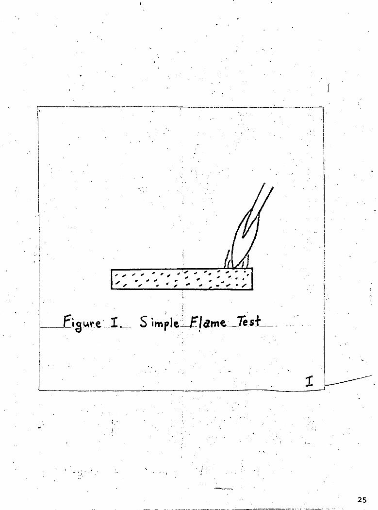
Fireproofing treatment initially, and widely used at the present time,
consisted of treating materials with inorganic salts. Borates and phosphates
are, and have been, widely used for this.purpose. A simple test involving
the application of a standard flame directly to the material can be used as
illustrated in Figure 1. If the treatment has been successful, flame will
not propagate away from the region of the torch and, when the torch is removed,
flaming or glowing of .the material will stop very quickly. The fireproofing
additive, if a borate or phosphate or similar inorganic material, may interfere
chemically with the free radical chemistry necessary for flame propagation.
In addition, the low melting oxides of: boron and phosphorus provide a barrier
between the organic material and the ambient air. While the flame is being
applied, it is possible that flammable;vapors are released and consumed by the
flame. If large amounts of flammable material were released, the flame would
flare up, which is not desirable. If small amounts were released, the vapors
would be consumed, and no additional hazard would be created.
Tests of this type have been used to rate materials. Let us consider,
however, a different condition.. In Figure 2, we assume that a source of heat
19

is applied to the material indirectly, either by means of a flame, as shown,
or some other heat source. The flammable vapors produced are not consumed
by the flame and diffuse away from the surface creating a concentration
gradient. Typical gradients for slow, intermediate and rapid gas evolution
are illustrated in Figure III. In Figure Ilia, the rate of gas evolution is
too lean to burn except very near the surface where surface quenching might
inhibit ignition and flame propagation. An ignition source near the surface
would not be a hazard. There may well be, as illustrated in Figure Illb, an
intermediate gas evolution rate which would produce a flammable mixture.
Ignition could occur and a fire might continue to burn as long as the heat
source was present to produce flammable vapor in spite of the fireproofing
material which may be present. The fire occurs above the surface and the
fireproofing material might not be effective if ,it is not vaporized. Although
such a material might pass a flame test it would still represent a fire hazard
in the presence of a less active heat source.
Finally, in Figure IIIc a very rapid gas evolution is illustrated. Such
a situation may not present an ignition hazard near the surface but the large
amounts of vapor produced could form flammable mixtures and ignite far from
the surface. Flash fires resulting from smoldering fabrics are often the
result of this type of behavior. A relatively fireproof material which does
not itself ignite can release enough flammable vapor to create a hazard in the
vapor space. The problem is compounded if the vapors released are also toxic
or debilitating.
These experiments have considered an external ignition source. The heat»•
source itself may also be the source of ignition. Figure II could easily have
represented a thermal ignition experiment. Here, too, the problem is quite
complex since two gradients are involved, a concentration gradient and a
temperature gradient. Some of the important factors are illustrated -in Figure
IV. The upper curve is a plot of the ignition temperature of the vapor (Tig) .
versus fuel concentration (F). It is assumed that some minimum temperature
exists and that ignition becomes more difficult at higher and lower fuel
concentrations. The solid line in the lower curve represents a fuel concen-1 I • , • ' ' > '. I . • , • t , ' . i l l
tration (F) curve versus height above the surface. On the basis of the Tig vs F• • • • • '. ; i .. . ' i i i. i , • ' . , . i . ! .1
and h vs F' curves it is possible to generate a curve shown as a dotted line
20

which represents the required ignition temperature at any point above the
surface. The ordinate remains height above the surface, h, and the abscissaf
becomes Tig. If the actual temperature due to the heat source exceeds Tj3at any point, ignition will occur, {in Figure IV, if the fuel gradient curve
had been a temperature gradient curve, ignition would have occurred. Once
ignited, of course, the flame might -propagate over the entire sample. Since
both fuel and temperature gradients are important it is easy to see that
such an experiment would be quite sensitive to rate of heating, heat transfer (
rates, diffusion rates and other experimental variables.
The problem becomes even more complicated if there is a flow across the
surface. One example from the work -of Gerstein and Hyde (Ref 1) is illustrated
in Figure V. The configuration is illustrated schematically. It consists of
an air flow of velocity V parallel "to the surface. The flammable vapor leavesCO '
the surface at right angles to the flow and to the surface at a velocity V as
a mass flow, p V . The value of V would depend on heating rate, for example
and represents a quantitative measure of the rate of flammable vapor evolution.
The lines indicate the existence of ,a flammable mixture at two differnet
stations along the surface, 0.4 ft from the start and 1 ft from the start. For
a given air velocity, 10 ft/sec, a higher gas evolution rate is required .at 0.4
ft than at 1 ft. The boundary layer is thin at 0.4 ft and the air dilutes the
mixture which is flammable further away. At any specific location, more,heat
or a greater gas evolution rate is required as the air flow velocity increases.
Between the two curves there is a region where ignition could not take place ift 1
the material was small (0..4 ft) but 'could take place if the material were large.
These calculations can easily be related to shorter materials and lower velocities
so that the conclusions are general„ It is evident that the occurrence of ignition
is strongly dependent on the complete environment and not on any single factor,,
The fireproof ing expert must take thjLs into account and define the conditionsit ,
under which his material or his treatment is applicable*
More recently, fireproofing techniques have involved the use of specially
formulated polymers or additives of Ian organic nature combined with the plastic
or fabric. The freon type halocarbons containing bromine, chlorine and fluorine,
have been used for this purpose and- various halogenated monomers have been
polymerized to form fireproof plastics. Depending upon the decomposition
characteristics of the polymer and the relative release of fuel components and
21
inhibitor components, the preceding discussions may still be applicable.
Other factors must also be considered. Some work of Gerstein and Stine
(Ref 2) with mixtures of fuels and carbon tetrachloride is relevant.
Consider the case of Figure 2 but assume that the vapors released consist
of a mixture of fuel and inhibitor. Flammability limit curves such as
illustrated in Figure VI result. We have plotted the partial pressure of
inert !br 'inhibiting material versus the partial pressure of fuel. At
P. = 0 we would have the normal lean and rich flammability limits in
the absence of inhibitor. At some value of P. . and above all mixturesinertwould be non-flammable. Figure VII shows how such a curve can be generated.
If the initial material had a composition NI , heating of the vapor could
generate the curve shown. At some stage, since the inhibitor comes off
less rapidly than the fuel a flammable mixture results indicated by X. As
the initial composition is changed, the behavior changes until finally:a
composition is reached at which ignition does not occur during the entire
heating period. The sample of initial composition N, would be judged as :
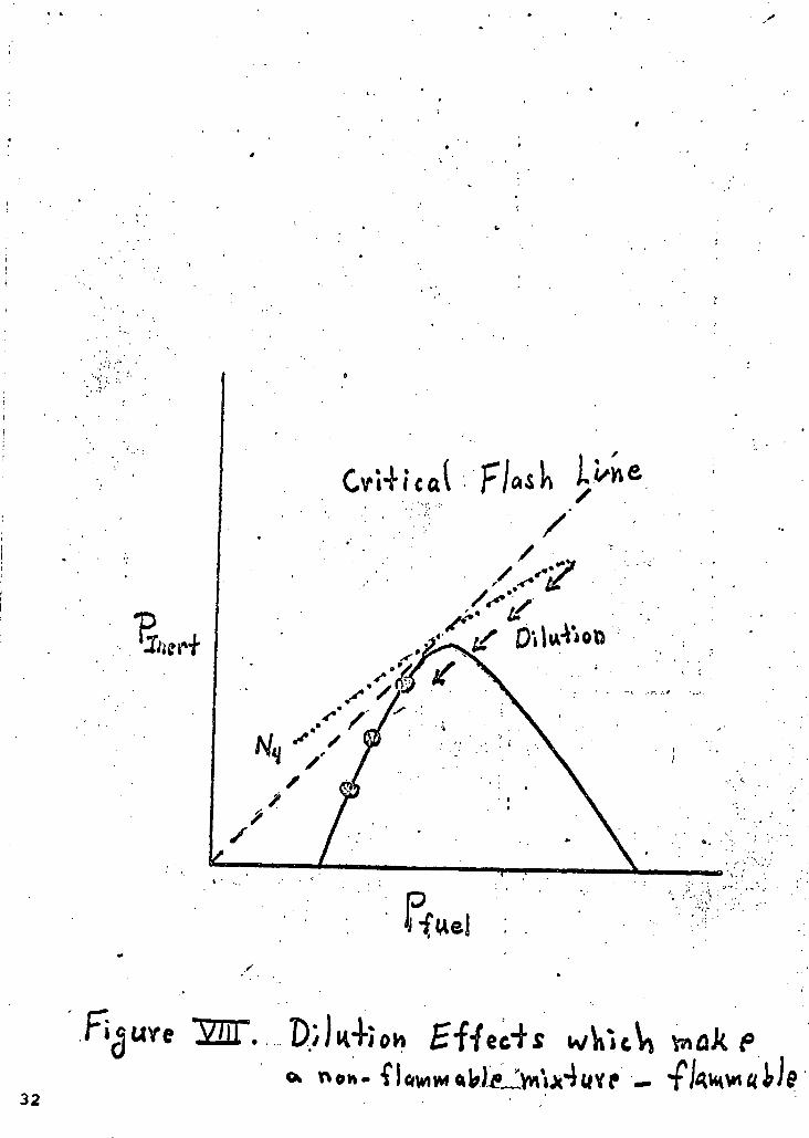
non-flammable or fireproof. Examine Figure VIII to see what happens as
this "non=flammable" mixture is diluted by air. Dilution reduces both
P. . and P. . but the ratio P. J?e i remains constant:. Dilution isinert fuel inert fuelrepresented by a straight line through the origin from the location of the
final mixture. It is shown in Figure VIII by a series of arrows. The non-
flammable mixture crosses into the flammable range and ignition is possible.
Again, the purpose of this example' has been to emphasize the importance of
defining the exact conditions of the test and environment before the labels
of fireproof or non-flammable are applied.
I have not tried to summarize the large body of literature on fire-
proofing. Rather I have taken advantage of the prerogative of an introductory
speaker to raise questions rather than answer them. Specifically I have
tried to emphasize the great importance of defining the exact conditions under
which a material is fireproof and the awareness' that "fireproof" materials
can burn or lead to fires under conditions different from those evaluated by
a single test. I have not touched on the many other problems faced by the
22

fireproofing experts including the physical and structural properties of
the materials, possible toxic gases released by thermal decomposition,
cost and fabrication difficulties. The papers which follow illustrate
that major progress has been made in the field of fireproofing. Much more
still needs to be done.
23
REFERENCES
1. Gerstein and Hyde, "A Boundary Layer Model For Pilot Ignitionof Cellulosic Solids in a Wind (to be published). Based onEngineers Degree Thesis, August 1970, University of SouthernCalifornia.
2. Gerstein and Stine, "Anomolies in Flash Points of Mixtures ofHalogenated Hydrocarbons and Flammable Liquids (to be published),
24
' X-
X „
jB.q.uv.el-I- S implei-£/5rne_J7esio • . . «
25

Flammable
_LUJY//////////////////////A
kJ^^
26

CO
{ft h
o
-0
-Bg.«f.e_H.__ Cpnc«ri4f_«4a0»L_
Surface
nn
near A
27

'3
hg
28

Ut
•o-f
,01
ft /sec
X V u r e ^{-fecil of -f/ooo on •forma4»o r m a » o v } o
29

r,
30

31
Rfuel
Figure
32
"UTILIZATION OF AVAILABLE SKILLS &
MATERIALS IN FIRE PREVENTION"
Speaker: Deputy Chief Harry W. MartinFire MarshalLos Angeles, California
33

Harry W. Martin/ ,
Deputy Chief and Fire Marshal
City of Los Angeles Fire Department
Currently the Fire Marshal and Commander of the Bureau
of Fire Prevention of the Los Angeles City Fire Department,
Mr. Martin has been a member of the Fire Department for 28
years. He has also lectured on fire protection and engineering
at various seminars at the University of California at Davis,
UCLA, USC, Chabot College at Hayward, and Phoenix College
at Phoenix, Arizona.
Mr. Martin attended Los Angeles City College and Gal State
in Los Angeles where he majored in civil engineering with
minor studies in physical sciences and public administration.
Mr. Martin has been a consulting fire protection engineer' . •.' • " '•" ' > ' . . ' . . . . ' . " ' "-*"-•-
and expert witness in legal action in numerous states.
f->H '
>'
35

FIRE PROTECTION FOR LARGE OFFICE BUILDINGS
I. Planning Stage ;
A. Determine type of occupancy
B. Special requirements for different occupancies.
C« Consider water supply available to building
1. Supplemental fire protection may be required whereaccess is restricted
2. Supplemental protection may consist of on-site hydrants
D. Distribution of water supply in building for fire fighting5
1. Combination standpipeg •&•*•
a. Wet standpipe system
b. Connected to fire pumps
c. Fire Department cqnnections for second source ofsupply I
d. Gravity tanks may be required according tobuilding height ;
e. For use by Fire Department
2. Interior standpipes . '
a. For use by building occupants
bo Connected to combination system and gravity tank
E. Exits (types)
1« Enclosed stairway
2. Conventional smoke-proof enclosure
a. Located on exterior wall
b. No opening directly into interior of the building
37

3. Mechanically ventilated smoke-proof enclosure
a. Located in building core
b. Involves a system of smoke detectors andmechanical ventilation
F. Emergency power
1. Required to light exits and exit signs during powerfailure
2. Supply power to mechanically ventilated smoke tower
G. Extinguishing systems
1. Sprinklers required in below grade areas
2. May be required in lieu of other protection
II. Construction Stage -
A. Water supply
1. Extend standpipe as building goes up.
2. Provide fire pump
B. Special problems
1. Vertical and horizontal access limited
2. Accumulation of combustibles , . ' •
. a. Trash
b. Packing material
c 0 Lumber .
3. Flammable liquids
a. Paint spraying , -
b. Adhesives
4. Welding and heating devices being operated .
38

5. Special detection and extinguishing systems may beincomplete
6. Communications system in building often lackingj
III. Final Testing of iFire Protection Systems •'
A. Standpipe system
1. Each riser flowed from topmost outlet at 30 p.s.i.for one minute
2. Fire pump
a. Operated for one hour
b. Started three times automatically and three timesmanually ;
c. Tested to 150% of its rated capacity for 15 minutes
B. Emergency power system
1. Tested upon completion
2. Must provide rated capacity
C. Mechanically ventilated smoke-proof enclosure
1. All smoke detectors checked
2. Ventilation and pressure differentials checked
3. All accessory equipment must function properly
IV. Maintenance r
A. All fire protection systems to be tested at least everyfive years.
1. Combination standpipes
2,, Wet standpipes
3. Automatic sprinkler systems
39
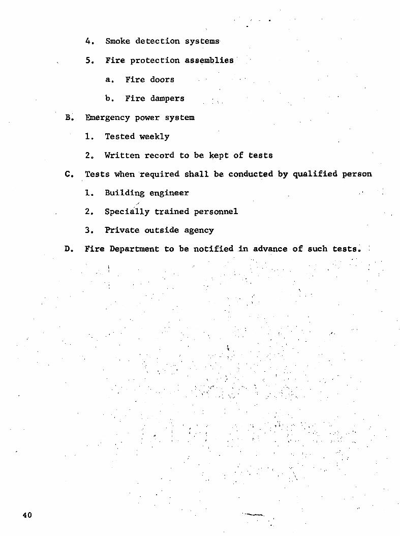
4. Smoke detection systems
5. Fire protection assemblies
a. Fire doors
b. Fire dampers
B. Emergency power system
1. Tested weekly
2. Written record to be kept of tests
C. Tests when required shall be conducted by qualified person
1. Building engineer
2. Specially trained personnel
3. Private outside agency
D. Fire Department to be notified in advance of such tests.
40

"HOW TO REDUCE YOUR FIRE INSURANCE RATES"
Speaker: Myron DuBainSenior Vice PresidentProperty UnderwritingFireman's Fund Insurance Co.San Francisco, California
41
Myron DuBain j
Senior Vice President of Property and Casualty
Fireman's Fund American Insurance Company
Mr. DuBain joined Fireman's Fund Insurance Company in
1946 and since then has held several executive positions with
the company. Among them are the Vice President with senior
executive responsibility for Inland Marine operations, senior
executive responsible for Inland Marine and Commercial Multiple
Peril operations, senior executive for all Property and .
Multiple Line operations, and his present position of the ;. , ' " - . i
senior underwriting executive for Property, Casualty and
Multiple Line operations which he has held since 1968.
Mr. DuBain is a member of the Factory Insurance Association,
the Fire Insurance Research and Actuarial Association, and' . ' ' . • ' ' " •" •'-.'•"•'•'•the Oil Insuraiice Association.
f
He received a bachelor's degree from the university
of California at Berkeley in 1943 and attended the Stanford
University Graduate School of Business Executive Programi n ' ' ' " ' ' '
43

HOW TO REDUCE YOUR FIRE INSURANCE RATES
To correct any mistaken impressions that could result from the title of my
address, I should make it clear that I am not an insurance rate technician. We
have rating technicians who devote their entire time to the principles and applica-
tions of rating schedules and individual risk rate make-ups. My own involvement is
limited to the broad general principles and overall results of the detailed rating
system in our various property and casualty lines.
I might also remind you that insurance companies are in business to make money,
although the level of profit we seek is modest. Nevertheless, we do have a profit—
as well as a public service—motive, just as those of you who are in the construction
trades or who are building and plant owners.
Fire insurance premiums are essentially the product of losses plus the necessary
expenses of the insurance company to do business. In any major rating classification,
the class itself establishes its own rates over long experience periods. I emphasize
that the rating system recognizes long experience periods because in high-valued
properties, a large single loss can distort the short-term averages. Of course an
individual loss would not, in itself, have sufficient credibility for ratemaking
purposes. /
The important thing is that if losses go up, insurance rates are going to have
to go up. So the simplest way to reduce your fire insurance rates is to reduce your
fire insurance losses, and to get others to do likewise.S'
With that primer in ratemaking, let's take a closer look at how the insurance
underwriter looks at property insurance.
Historically, the attitude of underwriters toward buildings of fire resistive
construction has been quite favorable and the underwriting treatment accorded them
quite liberal. Until recent years, most underwriters would not hesitate to freely
commit their full capacity on fire resistive structures, subject to minimal inspec-
tion requirements.

The practices in the building trade were generally toward heavy masonry construc-
tion, the combustibility load of such things as high-rise office buildings was light
and, generally, good fire cut-off standards were followed between floors. Consequently,
subject to underwriting of the occupancy plus an assurance that any special hazards
were adequately recognized and cared for, this was considered very desirable business.
The loss experience was good and the rates reflected this until they reached almost
minimal levels.
Today, things are different. During the past few years, we have seen some
drastic changes in construction methods and materials. We are now seeing an increasing
number of multi-million dollar fires in so-called fire resistive buildings occurring
out of these changes in construction and materials.
Since the'end of World War II, our booming economy has created a huge demand for
more and better office, plant and storage space. Many new, attractive materials have
been appearing on the market with resultant changes in building methods in order to
utilize them. Sky-rocketing labor costs have resulted in the development of labor-
saving construction techniques.
The financial squeeze put on municipal governments dictated a broader tax base,
so it became politically expedient to allow building code variances in order to speed/
up development of commercial properties. In some major cities building codes have
been completely revised, and not always for the better,.
This combination of experimental designs, untried materials and relaxed code
requirements has given us many buildings which no longer have the same high degree
of fire resistance we once knew and which, in many cases, do not provide adequate
life safety for occupants. /
Let me give you two examples of the new type fire losses we are experiencing in
many so-called fire resistive buildings. .
A typical, modern 50 story skyscraper in New York was completed in early 1970.
The building has a reinforced concrete center core which contains the elevator
46

shafts, stair towers, rest rooms, utilities and air conditioning supply and return
air shafts. Steel girders connect this core to columns at the outside wall of the
building so that the floors are column-free except at the east and west sections.
Beams support the 2-1/2" thick concrete floor on fluted floor form units and
are joined to the concrete floors by steel studs. Columns, girders, beams, and the
underside of floors are protected by sprayed asbestos fibre to provide a four hour
fire resistance for columns and three hour rating for filler beams and floors.
Walls are made up of aluminum panel window sections which also encase the
outside columns. There is a 6" concrete block curtain wall 28" high built:on the
outer edge of the floor slab. This wall is located in line with the center of the
wall columns so that the outer skin is 16" out from this wall. This separation
creates vertical flues the height of the base o'r tower which is 143' maximum, which
are interrupted at each floor level by an aluminum metal flashing designed to collect
condensation and carry it through weep holes to the outside.
The inside face of the curtain wall, the space between the windows, and the\
space above the windows is insulated with 1" Dorvon FR 100 Polystyrene foam board.
This insulation is covered on the inside by gypsum board only where visible. There
is no covering on it above the hung ceiling. As a result, the protection between/ : '
the concealed ceiling spaces of two floors consists of two 1" thick pieces of foamed
polystyrene and a thin sheet of aluminum.,
The concealed space between the hung, ceiling and the floor above contains air
supply ducts, lighting fixtures, power lines and conduit, telephone cables and
communication cables. .
During the application of finishing touches for occupancy of luxurious offices
by a new tenant, on the 31st, 32nd, and 33rd floors, a guard on the 33rd floor saw
smoke above the ceiling through an opening and reportedly pulled the fire alarm box
on his floor. He then took the elevator to the first floor to notify the building
guards of the fire. . *"'""
47
48
two guards and a telephone installer supervisor took the elevator to the 39th
floor to notify other employees of the fire. Their elevator stopped at the 33rd
floor, and smoke and flames rushed in. The elevator would not move from the floor
with the result that the two guards perished and the telephone foreman was barely
alive when rescued by firemen two hours later.
The Fire Department responded within three minutes from the time the alarm was
received, but. when they arrived, the 33rd and 34th floors were raging infernos with
so much smoke and heat that the firemen could only operate on the floor for a short
time.
It was five hours before the fire was brought under control and in those five
hours, two lives were lost, 30 men were injured and damage totaled ten million dollars.
The 33rd, 34th, and 35th floors were burned out, with varying degrees of smoke
and heat damage to many additional floors above and below. .The fire spread to the
exposed polystyrene foam in the south and east walls and emerged from the concealed
space in the form of flaming droplets of flaming gases.
As the heat involved furniture stuffed with feather or foamed polyurethane, its
progress accelerated because of the amount of combustibles and flammable gases given
off. Tests made' after the fire showed that the polyurethane foam gave off flammable
gases at 212°F.
I would like to read to you excerpts from the official investigation report of
this fire by the New York Board of Fire Underwriters.
"The reason for the severe fire in this fire resistive building can be understood
if it is realized that the building classification is a misnomer. Buildings of this
type erected in this plastic age should more correctly be called 'semi-combustible.';
Except for the concrete and metal, almost everything in the building is combustible
to some degree - foam plastic wall insulation, electrical cables, ceiling tiles,
partitions and insulation on air handling units. The degree in some cases is small
but added to the severe fire hazard caused by foamed plastic furniture, there is the
recipe for this conflagration.

"The degree of damage to the steel frame is the result of several factors.
It is reported that this steel came from England and became severely oxidized in
transit. As a result, the sprayed asbestos fibre did not adhere well in many places
and fell off along with the scale shortly after application. As a second factor,
this insulation was removed in many locations where partitions were run to the
underside of beams, where air ducts ran under beams, where clamps are attached,
where wires scrape it. The situation that exists in a laboratory when this material
is tested is not the same situation that exists in the field."
That last point is important. Time and time again we have blindly and in good
faith accepted laboratory tests of the fire resistance of new materials, only to have
the materials not prove out when it really counted. Well, I think underwriters-tfiive
been burned once too often. We are going to be taking a much more critical look at
both the design and materials characteristics of new construction, and we are going
to be much more cautious in accepting and rating risks. The report I just referred
to puts it this way:
"This fire has provided a major full scale test for new methods of construction.
The transmission of fires between floors, the distribution of smoke throughout the
building and the failure of structural elements prove the necessity of reviewing the
present requirements and practices.
"Since this building is typical of a large number of buildings now being built,
recommendations are being made on a general basis rather than applying specifically
to this building."
The report lists 14 recommendations which I will not read now because of their
length. I do have two or three copies which you may pass around, however, and
additional copies may be obtained by writing to me at Fireman's Fund American
Insurance Companies in San Francisco. i . ' ••. •\
The second example involves a building in California in the course of construc-
tion. The structure had a total floor area of approximately 332,000 square feet.
This was a one equals two story building of 6 inch reinforced concrete tilt-up wallsi
...:- , 49

with reinforced concrete pilasters which were to have been divided into four fire
divisions separated by 6 inch reinforced concrete fire walls with fire doors and
dampers covering openings. The floor was concrete and the roof was composition
on wood decking on wood truss. '
The building was to be for a fruit processing and cold storage operation. The
entire east side of the building was divided into cold storage and cooler rooms
constructed of half-inch plywood on 2 X 4 wood stud framing extending from floor
to roof, with pplyurethane foam insulation sprayed on all walls and dividers and on
the underside of both the equipment decks and the roof.
At the time of the fire, the building was almost complete, with one section
occupied and cut off from the other three sections. The three sections not yet
occupied were not separated from each other in that the fire doors were not in
operation.
The fire was caused by a welder's torch while sweating a water pipe to cooling
equipment, igniting polyurethane foam insulation in the area of the cold storage
rooms. The polyurethane foam insulation, while a good insulating agent, was of such
high combustibility characteristics that the entire three uncompleted sections of the
building were totally engulfed in flames within approximately nine minutes from the/
time the fire started.
Several workmen on scaffolding at the opposite end of the building from which
the fire originated were barely able to escape in time to avoid injury. The three
sections of the building which were still not occupied were practically a total loss.
The ultimate loss was in excess of $4,000,000 on a building with a cost of $5,500.000.
Unfortunately, these two examples do not represent uncommon losses. A look at
statistics for recent years reveals an ominous trend: a $15,000,000 grocery warehouse
fire in Boston; a $3,000,000 fire at a school under construction in New Hampshire- -
and so the list continues.
The result of this can only be substantially increased fire and liability
insurance rates, because of the exposure to life and property. It is not surprising
50

that many insurance companies—including my own—are taking a closer look at the
so-called fire resistive buildings which we have considered superior risks eligible
for premium discounts under commercial package policies.
Instead of giving discounts, we may be asking for surcharges on some of these
buildings, particularly until we are satisfied that the lag in rate making has caught
up to the new loss trend. Indeed, in some-cases, I would not be surprised to see
available-insurance capacity become an acute problem in some hazardous type construc-
tion unless .there is considerable improvement in construction methods.
But the picture is not so bleak as it might seem. Rates can be reduced, and
the key to reducing them lies in incorporating-'.the many existing fire protection
methods into the initial stages of building planning, with diligent follow-through
in the construction phases. It is then that fire protection is least expensive and
most effective—not when it is thrown in as an ill-planned afterthought.
I would call upon you to exercise your leadership in making fire protection an
integral part of building design and construction, both through your own expertise
and with the help of qualified engineering personnel readily available to assess the
weaknesses and strengths of design. Most major insurance companies have experts•H"
ready to assist and advise in connection with proposed construction plans, and Fire
Rating Bureaus in practically all jurisdictions have experts who will respond, upon
request, in connection with building design and construction.
A prime example of the benefits to be. reaped from advance planning is a recent
fire at the University of California at Santa Cruz. Although losses totaled
$150,000, fire prevention experts revealed' that losses could have been substantially
reduced if the building had been sprinklered—at a cost of $6,000.
A second method of reducing fire insurance rates is, of course, reduction of
loss potential in existing structures. Essential to the success of any such program
is installation and maintenance of adequate fire protection systems, combined with
emergency-procedure training of personnel and pre-planning with local fire
departments.
1 51
Equally essential is a periodic inspection of the premisesl, followed by
correction of hazardous conditions—in other words, good housekeeping. Most impor-
tant of all, perhaps, is proper use of the facility--a building should not be used
for a purpose more hazardous than its design and construction permit.
Again, both insurance companies and Fire Rating Bureaus stand ready to provide
assistance--and I would urge you to take advantage of the advice.
In view of the location of this conference and because I am sure many of you
are from California and other West Coast areas, I would remiss if I did not mention
the fire hazard in the aftermath of earthquakes. The danger is a very real one, as
evidenced by such tragedies as the San Francisco disaster of 1906, but present
building standards seem destined to increase, rather t;han reduce, the exposure from
earthquakes.
We were very surprised to learn of the collapse or failure of several recently
constructed modern buildings in both the Santa Rosa earthquake in 1969 and the San
Fernando Valley quake which just occurred in February of this year. The distressing
part is that investigation by eminently qualified engineers following the failure
and collapse of some of these buildings clearly indicated they should not have been
a surprise.
I would like' to quote from page 58 of a study released by the United States
Department of Commerce on the Santa Rosa, California earthquake of October 1, 1969.
"Research on materials has led to their more effective use in buildings, but
not without side effects. Sprayed-on fireproofing around steel frames in lieu of
poured-in-place concrete fireproofing has greatly reduced the inherent lateral force
resistance of many structures, since the mathematically neglected concrete with the
steel frame members formed, in effect, composite members.
"Research on concrete,members has changed design practice to the extent that
allowable unit-design stresses have increased as much as fivefold in recent years,
creating new design problems such as overturning, multiple types of stress, concen-
tration, and concrete splitting. Metal and glass skin exteriors have replaced •
52
brick and concrete panel walls, thereby reducing inherent strength and damping.
Many other examples can be cited.
"The net effect of all of these developments has been to substantially reduce
the inherent lateral force resistance of buildings, unless the designer included• •*
noncode-required bracing. This extra bracing is too often opposed on the basis of
costs or a lack of understanding.
"In essence then, a designer who follows the letter of the law as expressed in
the building code, but lack experience judgement when extrapolating code values to
new types of structures, can inadvertently design a collapse-hazard structure which
is legally safe. Collapse is more probable today than it was several decades ago,
before changed practice had reduced a structure's uncounted strengths."
Thus, it is possible for a planned building to be considered legally safe, while
it is, in reality, a collapse-hazard structure. Equally disturbing is the fact that
code requirements have so changed within recent years that a framed concrete building
today is permitted to have about half the lateral force resistance—earthquake
bracing, if you will—than 'that required ten years ago.
On top of all this, we understand that the International Conference of Building
Officials, publishers of the uniform building code, now has before it a proposal to
further reduce the safety factor on concrete construction.
Gentlemen, as underwriters, we are concerned. I must tell you in all candor
that it is not a function of insurance to insure deficiency in design or construc-
tion method.
53

"NEW FIRE RETARDANT FOAMS AND INTUMESCENTS"
Speaker: Dr. John A. ParkerChief, Chemical Research Projects OfficeAmes Research CenterMoffett Field, California
55

Dr. John A. ParkerX
Ames Research Center
i National Aeronautics and Space Administration
Moffett Field, California
Dr. John A. Parker is Chief, Chemical Research Projects
Office, at NASA's Ames Research Center, near Mountain View,
California. The Chemical Research Projects Office is involved
in polymer research at Ames and is a problem-solving activity
in the fields of aeronautics, life sciences, and space
technology.
In 1968 Dr. Parker was awarded the NASA Exceptional
Scientific Achievement medal for his pioneering research in
reentry technology and on the ablation of heat shield materials.
The results of this work have been used to provide protection
from fire with a wide range of commercial application.
•** s
Prior to joining Ames as a Research Scientist in 1962,
Dr. Parker was manager of the Chemistry Department of Armstrong
Cork Company in Lancaster, Pennsylvania.'' He has also taught at
the Philadelphia Area Colleges on the campus of Temple
University and at the University of Pennsylvania.
He received his Bachelor's degree in chemistry from the
University of Pennsylvania in 1948, and his Master's and PhD
from the same university in chemistry in 1949 and 1951.
•-mm 5 7
PROTECTION OF AIRCRAFT IN GROUND CRASH FUEL FIRES
Carr B. Neel and Richard H. Fish
Ames Research Center, NASA, Moffett Field, California 94035Presented by Dr. John A. Parker at the WESRAC-Fireproofing and Safety Symposium, May 27, 1971,
Los Angeles, Calif.
INTRODUCTION :
Passengers caught in an aircraft ground accident that has resulted in fire have only a very short
time to escape. Those failing to exit quickly probably will die from exposure to heat and fumes.
As part of a program of development of fire-retardant materials at Ames Research Center, a
concept for passenger survival has been studied which differs from those that have been considered
in the past. Previous studies generally have stressed quick-evacuation techniques; some have dealt
with possible ways to prevent or control the fire. In contrast, the study at Ames was directed
toward the approach of surrounding the passenger compartment with a fire-retardant shell that
would protect the occupants long enough for the- fire to burn out or for fire-fighting, equipment to
reach the airplane and extinguish the fire. >
This approach has been made possible by the recent development of two new fire-retardant
materials: a lightweight foam plastic, called polyisocyanurate foam, and an intumescent paint. The
intumescent paint is 'a material that expands to many times its original thickness when exposed to
heat; thus, it insulates the surface on which it is applied. The/thermal-protection mechanisms of
these materials operate on the same ablative principles as those used to protect the astronauts./ .
during reentry. To demonstrate their use in a full-scale application, an airplane fuselage was fitted'
with the materials and tested in a jet-fuel fire.
This paper describes the fire-protection system and the fire test and presents an analysis of
some of the results. It should be emphasized that this constitutes a progess report and that a
number of problems remain to be solved before such a system can be used for passenger protection.
'£$"< /U59

PREPARATION OF TEST FUSELAGE
Considerations for Passenger Protection. In the design of a test to demonstrate how these
materials could be used to protect passengers, two factors influencing survival in a crash fire must be
considered. First, the penetration of heat must be minimized. At the same time, a way must be
devised to prevent the intrusion of smoke and toxic gases, which can be lethal even though the
temperature is controlled.
A factor that influences both of these threats in the case of a survivable crash is the structural
damage that results in rupture of the fuselage. Crash damage was not considered in the present test
nor was the presence of windows,, which also could be a point of heat and gas penetration. These
factors have been purposely omitted because it was believed that the basic concept of passenger
protection should be explored first. The effect of crash damage and the protection of windows will
be included in future studies. .
Installation of Fire-Protection System. Avco Systems Division of Lowell, Massachusetts, under
contract to NASA, installed the fire-protection system and conducted the test. For .the test Avco
procured a surplus McDonnell Douglas C-47 airplane and removed a 7.9 m (26 ft) long section from/ \the fuselage (Figure 7>P-They divided the section and capped either end by steel bulkheads, making
two equal sections typical of traditional airplane construction. One half was left essentially
unchanged; the other half was fitted with the thermal-protective materials to form a shell arounc
the passenger compartment. Thus, the test would validate feasibility of a retrofit system for existing;
aircraft. /
Tho-detaila of the installation of tho firo protection system are shown in Figure^. The circular
frames were first painted with intumescent paint 0.13 cm (0.05 in.) thick. Next, a layer of loosely
woven fiber-glass matting was bonded to the skin. The polyisocyanurate foam was sprayed over the
matting and was built up to the full 6.4-cm (2.5 in.) depth of the frames and 5 to 8 cm (2 to 3 in.)
over the floor structure. Excess foam was trimmed off. To finish the installation, a liner of fiber-
glass-epoxy laminate 0.08 cm (1/32 in.) thick was cemented to the foam and then riveted to the
frames. This laminate is similar to airliner decorative interior paneling. The floor foam was also
covered with the laminate, and all joints were sealed to exclude smoke and gases. Tho properties of
the foam used in tho toot arc given in table 1.
The tables and figures referenced are not included in this report.
60

In the unprotected section, the space between the aluminum skin and the interior paneling
was filled with 5 cm (2 in.) of fiber-glass batting, a material typical of conventional aircraft
insulation.
The steel bulkheads that divided the protected and unprotected sections and capped the two
ends were insulated with a 2.5-cm-thick (1 in.) commercial firewall insulation covered with 8 cm
(3 in.) of fiber-glass batting.
Instrumentation and Test Arrangement. The fuselage was instrumented to measure both the
exterior and interior thermal environments. Thermocouples were used to measure temperatures
both inside and outside the cabin. The exterior heat flux was measured by slug-type calorimeters.
Tho firo toot arrangement io Jlluotrotod in Figure 9. The test was conducted at Otis Air Force
Base, Massachusetts. The fuselage was placed directly on the ground and was flanked by two
shallow pits about 9 by 15 m (30 by 50 ft). Water was placed in the bottom of the pits, and 9.5 m3
(2500 gallons) of JP-4 fuel was floated on top of the water in each pit, forming two large fuel
ponds. Water-cooled probes containing motion-picture cameras and gas-sampling equipment, were
positioned at either end of the test fuselage so that they could observe the interior of each section.
The probes were arranged so that they could be withdrawn when temperatures became excessive.
Several cameras were placed around the vehicle to record the test.
Tho ontorior of tho fuoologo boforo tho toot io ohown fn Figure 10. The interior of the
protected section before the toot ic chown in Figure 11. Simulated exit signs and an optical target
were installed to permit evaluation of possible smoke effects. The interior of the unprotected
section appeared much the same as the protected section, except that no exit signs or optical target
was installed.
Test Plan. The plan was to ignite both ponds of fuel simultaneously at several points to obtain
a uniform buildup of flames over the surface of each pond. The quantity of fuel and configuration
of the ponds were calculated to envelop the fuselage completely with flames and to expose the
vehicle to maximum heat flux for 10 minutes. It was believed that the unprotected section would
be destroyed within 1 to 2 minutes. The protected section hopefully would survive the fire, but fire
trucks were stationed nearby in the event that certain monitored thermocouples indicated flame
intrusion. i .
61

FIRE TEST
The test was made on August 13, 1970. Within Vi minute after ignition, the fire was fully
developed. By this time, smoke had already started to penetrate the unprotected section. Occupants
of this part of the cabin would have had to have evacuated the vehicle by this time to have survived.
Two viowG of the firo during the toot arc ahown in Figure 12./
Throughout most of the test, the entire test section was completely engulfed in flames.
Because of the volume of flames and smoke, visual observation of the test section was difficult.
About 5 minutes after ignition, a light wind arose from the southeast and directed the flames so
that occasionally the end of the protected section was visible. Accompanying this flame shift was a
tremendous vortex action of flames around the entire fuselage. This swirling action continued for
about 30 m (100 ft) upward. Peaks of the flames reached a height of approximately 60 m (200 ft).
Motion pictures of the interior of the unprotected section, although obscured by dense smoke,
show flame penetration within 1 minute after ignition. After 2 minutes, the unprotected section
apparently collapsed and was completely destroyed.
Meanwhile, in the protected section, the motion pictures showed no smoke, the gas-sampling
probe showed no toxic gas, and the thermocouples showed no temperature change. A power failure
prevented further motion pictures of the interior and necessitated removal of the probe containing
the motion-picture cameras and the gas-sampling equipment after 5.5 minutes. The last gas sample
was taken 5 minutes after ignition and still showed no toxic gases.
The fire lasted for 12 minutes, at which time the fire in the ponds burned out, and only
residual flames remained around the edges where fuel had soaked into the dirt mounds surrounding
the ponds.•
Following the test, the visual comparison between the protected and unprotected sections was
dramatic. Figure 13 shows virtually no trace of the unprotected section, whereas the foam-
protected fuselage is intact. The interior appears habitable, as shown by Figure 14* Some time
during tailoff of the fire, flames reached a relatively unprotected floor seam along the top of the
dirt mound supporting the test section. Heat penetrated at this point, and eventually resulted in a
62

slight burn-through, which caused considerable blackening of the walls. This occurred after the main
fire burned out and is attributed to the design of the test and not to a failure of the thermal-
protective system. , .
Soon after the fire died down, fire hoses were played on the test section, to preserve it for
study, and on the remaining flames around the edges of the ponds.
RESULTS AND DISCUSSION
Cabin Air Temperatures. The cabin air temperature histories were used to analyze the results.
These historioo aro plotted in F'guro 15. In the unprotected section, the air temperature rose to
300° C (600° F) in less than 2 minutes after the start of the fire and was climbing rapidly. By this .
time, the unprotected section was destroyed. In contrast, the temperature in the protected section
changed very little for the first 6 minutes; then, as the heat finally penetrated, the temperature rose
faster, reaching 150° C (300° F) as the fire burned put in 12 minutes.
To give an idea of the chance that passengers might have had of surviving inside the cabin, a
curve labeled "Human tolerance limit" has been plotted. This curve is a composite of two studies of
exposure of humans to extreme heat • and represents more severe conditions than existed in
our test. Also shown for comparison is the exposure envelope For the sauna-bath ritual, which calls
for repeated exposures of 10 to 15 minutes at temperatures from 80° to 100° C (175° to 210° F).
This is done for the health. The fact that the temperature in the protected section just reached the
human tolerance limit (for more severe conditions) in 12 minutes, as the fire burned out, indicates
that, if temperature were the only consideration, passengers could have survived for this time.
Generation of toxic gases is as important a consideration as temperature. Up to 5 minutes into
the test, no toxic gases were generated. At this point, the gas-sampling probe was withdrawn;
therefore, no measurements were made late in the test. During the last few minutes before burnout
of the fire, segments of the fiber-glass-epoxy liner reached temperatures at which partial decomposi-
tion of the resin might have occurred. Gases might have been generated that could have beeni
somewhat toxic. Although such gas generation was a possibility, the amount of toxic fumes was not
believed to have been sufficiently high to have influenced survivability, even at 12 minutes.
If this test represented an actual airliner crash;fire at an airport, fire-fighting equipment
generally could have reached the airplane and extinguished the fire in less than 8 minutes. At this'
63

point in the test, conditions were much more favorable for survival than at 12 minutes, and there
would be no question of either heat or toxic gases endangering life in the cabin. Thus, the concept
of passenger protection was adequately demonstrated by this test.
Consider again briefly the analysis of the cabin air temperature. After the fire burned out in
the ponds, small flames remained along the sides of the test section from residual fuel that had
soaked into the dirt mounds surrounding the ponds. At 12.5 minutes after the start of the fire, the
air temperature suddenly increased, indicating flame intrusion into the cabin. The cracks at the
floor-wall intersection are believed to have occurred at this time. The cause of the cracks, which
resulted from melting structure, is discussed later. The flame intrusion was probably rather small,
being limited to the low flames remaining at the edges of the ponds. At 14 minutes, water hoses
were played on the protected section and on the remaining flames, causing the cabin air tempera-
ture to drop rapidly.
Sources of Cabin Heating. Although the system of foam, paint, and fiber-glass liner gave
satisfactory protection, ways were explored to improve the system, with the objective of indicating
how the weight might be reduced. The most useful information from this standpoint is the thermal
data. Accordingly, these data were analyzed to identify and evaluate the sources of heating. To aid
in the analysis, temperature histories at various locations in the cabin for the last 5 minutes of the
test were plotted. A typical history for throe locationo in tho Cabin io given in Figure 16i Shown in
this figuro-is the temperature of the air measured in the middle of the cabin, on the fiber-glass liner
at a location alongside the air thermocouple, and in the foam 0.6 cm (1/4 in.) away from the fiber
glass. Note that the temperature of the air was higher than that of the fiber-glass liner, and the liner
temperature was higher than that of the foam. This means that the air was heating the sidewall of
the cabin. This reversal in heat-flow direction was unexpected, and it indicates that most of the
cabin heating came from heat leaks rather than through the main area of the side walls.
Two sources of heat leaks are identified by the temperature hiotorioo ohown in Figure 17. The
temperatures were measured over a frame and on the fiber-glass liner opposite a region of the foam
that had fissured. At both of these points, the temperatures were well above the air temperature.
These temperature histories typify the two primary sources of heat leaks. The frames formed highly
conductive heat-flow paths through the foam. Calculations indicate that about one-third of the total
heat input to the cabin for the last 5 minutes of the test came through the frames. Fissuring of the
foam was the second source of heat leaks. The sudden increase in fiber-glass-liner temperature
64
indicates the appearance of a fissure in the foam. These fissures apparently were the primary source
of heat leaks into the cabin, and, according to calculation, contributed over half the heating of the
cabin. A photograph of theoo fioouroo uftor tho toot io oh own oo Figure 18. The deep cracks, some of
which penetrated clear to the fiber-glass liner, were obvious heat-flow paths to the liner.
To minimize heating from the frames, the obvious solution would be to insulate the fiber-glass
liner from the frame flanges. Because of its low thermal conductivity, isocyanurate foam would be a
good material for this application. Calculations indicate that, if 1.3 cm 0/2 in.) of foam were placed
between the frame flanges and the fiber-glass liner, the heat input from the frames could be
decreased to one-fifth of the value with no insulation. ;
The problem of fissuring of .the foam is one that needs further study. Tests have shown that
isocyanurate foam in the lower-density range (30 to 40 kg/m3 (2 to 2.5 lb/ft3)) does not fissure.
Laboratory studies made since the fire test show that the lower-density foam, because of its greater
integrity, provides thermal protection equivalent to that of the higher-density foam (65 kg/m3 (4
lb/ft3)) used in the fire test. This means, of course, that the lower-density foam should give as good
protection in a fire as was provided in the test by the higher-density foam. Use of the lower-density
foam would have the advantage of providing a much lighter installation.
There are several possible explanations for the fissuring. The most obvious one is that the
higher density creates greater stresses upon heating of the foam.than the lower density. Spraying the
foam, which undergoes an exothermic reaction upon curing, against cold aluminum structure might
create built-in stresses that are relieved when the foam is heated. Other processing problems could
also have led to the conditions that caused fissuring. These various possibilities must be studied to
eliminate fissuring. .
Floor-Line Failure. Another area for improvement is the design of the floor-line protection. In
order to understand how to improve the design, the cause of failure during the fire test should be' ' i
examined. Figure 19 illuotratoa how tho failure developed. Dirt had been banked part way up the
fuselage wall to create a mound that formed one side of the fuel pond. The mound stopped just
below the floor line. This protected the bottom part of the fuselage from the fire, but left exposed a
portion of the structure just below the floor line. Heat from' the fire finally melted the exposed
frames to which the floor beams were fastened. Thus, the support for the floor was removed and
this caused the floor to sag just as the fire was burning out.This opened the floor-line cracks and
allowed the flames to enter the cabin.
65

In the foam installation, the floor foam was placed on top of the floor structure, where it did
not protect the primary structure. This installation proved satisfactory for the test of the protective
concept, but an improvement in design of the protective system would be required for an opera-
tional installation. To protect the floor structure properly, the foam should be placed under the
structure, OQ ohown in Figure 20. The foam should surround the primary structure to protect it
from melting.
Weight Penalty. Because of its ablative character, the fire-retardant foam generally provides
increased fire protection with increase in density. Accordingly, the foam in the test fuselage was
made heavier than usual, with the intent of providing protection equal to the protection that would
have been obtained from a thicker.application of lower-density foam in a larger airplane. Analysis of
the data from the fire test indicates that the foam installation was heavier than needed for adequate
fire protection.
Now consider the various factors that would permit a reduction in weight. First of all, as was
mentioned previously, by minimizing the heat leaks, one could expect improved thermal perfor-
mance, which would permit a reduction in weight. In fact, the indication was that the foam density
could be reduced from 65 kg/m3 (41b/ft3) to about 40 kg/m3 (2.5 lb/ft3) with no reduction in
performance. Also, by designing for a -shorter protection time, such as 8 minutes instead of 12
minutes, the required protection and the corresponding weight could be further reduced.
Based on these considerations, an estimate was made of the weight penalty for installation of a
fire-protective system in a typical modern-day airplane — an airliner with a gross weight of 180,000
kg (400,000 Ib). The increase in weight is estimated to be 1.5 kg/m2 (0.3 lb/ft2) of protected
surface area. This would increase the gross weight 770kg (1700 Ib). The corresponding increase in
structural-weight fraction would be from 30.0 to 30.4 percent.
It should be pointed out that the protective system discussed in this paper would be
essentially a retrofit installation for airplanes currently in service or in production. The foam would
be added for the single purpose of fire protection. No advantage would be taken of its other useful
characteristics, such as high compressive strength and compressive modulus or acoustical damping
properties. To utilize the foam most effectively, the foam and structure should be integrated at the
beginning of the structural design phase for a new airplane. With this approach, it is conceivable that
the structural gain would permit the addition of foam with no weight penalty.
66

CONCLUDING REMARKS
A test that constitutes a first step in developing a system to protect passengers in a crash fire
has been described. Many problems, such as protecting against fuselage rupture and providing
protection for windows, must be solved before such a system can be used. Nevertheless, results of
the test give promise of providing protection for passengers caught in a crash fire.
67

THE PERFORMANCE OF LIGHTWEIGHT PLASTIC
FOAMS DEVELOPED FOR FIRESAFETY
By Richard H. FishNASA Ames Research Center
Presented by Dr. John A. Parker at the WESRAC-Fireproofing and SafetySymposium, May 27, 1971, Los Angeles, California
ABSTRACT
Research on the chemistry of ablation for protection of spacecraftduring atmospheric entry has led to the development of a new class offire-retardant materials; namely, lightweight plastic foams. The foamshave been developed principally to protect aircraft structures and ex-ternally mounted fuel tanks from onboard fires in flight.
Fire-retardant foams have been made from urethane, isocyanurate, and
polybenzimidazole. The density of the fcams•ranges from 2 to 30 Ib/ft .Addition of randomly placed quartz fibers to the urethane and isocyanuratefoams increases their density and improves the stability of the charformed on heating. For example, by adding fibers in a 10-percent concen-tration, the density of the urethane foam is tripled and the fire-protection capability is increased fivefold. The fire-protectivecapability of the isocyanurate foam system is, twice that of the urethanefoam and four times that of commercial isocyanurate fire-retardant foam.
The various fire-retardant materials are described in this paper, andthe performance of .these materials when exposed to a fuel fire is illus-trated. Wherever possible, performance is compared with presently avail-able commercial developments. Although the materials were developedprimarily for aircraft use, a discussion is given of other possible areasof application.
INTRODUCTION
The work at Ames Research Center on fire<protection and fire sup-pression was started in September 1967 and was motivated by the realiza-tion that the principles utilized in the protection of entry vehiclesfrom aerodynamic heating could be used to give some, measure of protection
69

from both spacecraft and aircraft fires. The use of a low-density,polyurethane-based foam material to suppress a fire and to provide pro-tection for the structure of an aircraft or spacecraft will be discussedand described.
In this program, certain ground rules were established that hopefullywould avoid the normal long leadtimes between the generation of an ideaand the production of a final useful product. First, a team of special-ists from a number of organizational segments at Ames Research Centerwas gathered so that special skills could be concentrated on the problemin all disciplines.needed. Second, it was stipulated that only commer-cially available materials were to be used in the first phase of theprogram to avoid the time delays in inventing and producing new materialsystems. These actions provided rapid progress and produced a usefulproduct that could be improved further with additional work.
THEORY
The protection of any structure, entry vehicle, or aircraft againstdamage by heat can be accomplished by the same basic protective mechanisms,The source of heat is not important; heat generated by fire or by a hotgas cap surrounding an entry vehicle is much the same. To damage a struc-ture, heat must be carried to the structure by either free or forced con-vection or by radiation. Therefore, in principle, any or all of theheat-protective mechanisms can be utilized to afford protection(fig. 11-1).
The simplest:form of heat protection is one that provides a highresistance to heat flow between the heat,source and the structure. Low-density foam with'a low thermal conductivity provides this feature. An-other important mechanism, often overlooked in -fire protection systemsbut widely utilized in spacecraft thermal-protection systems, is the re-lease of gases from the thermal-protective material when subjected toheat lo&d. 'These gases serve to protect the system in two important ways.First, gases near the surface flow against the incoming heat, thus imped-ing the flow of heat to the surface. For example, in a spacecraft beingprotected against reentry heating, gases can block nearly all the con-vective heat flow* Second, in protecting against a fuel fire, gases canbe made rich in halogens that can chemically scavenge the chain carriersby which fuel flames are propagated and thus serve as fire-extinguishingagents.' This principle has been utilized in the polyurethane systems.
Another mechanism that affords protection against fires is a pro-duction of char resulting from the action of heat on .the materials. Ifchar with low thermal conductivity and high oxidation resistance can be
70

formed, it will not only afford protection by virtue of low thermal con-ductivity, but the surface will reach a high temperature and thus willbe capable of reradiating a large fraction of the incident heat load.This mechanism is utilized in the systems that are being developed. Inthe polyurethane foam material, polyvinylchloride has been added, which,when heated, causes the polyurethane to form a stable, tough char of lowthermal conductivity. This idea came directly from work on thermal pro-tection systems for reentry vehicles.
An important point about the systems to be discussed is that thesesystems react to an applied heat load to provide a number of protectivemechanisms not present in a system that does not respond to a fire. Thus,these are not passive systems; rather, they are dynamic systems that pro-vide protection when exposed to a fire.
MATERIALS
The properties desired in a foam system for fuel-fire protectionare as follows.
1. Impact ignition
a. Low density-void-filling capacity to eliminate atomizationof combustible liquids
b. Closed-cell foam structure with self-sealing skin to preventoutpouring of combustible liquids
c. Pyrolysis at low temperature and at high rate to give hydro-gen bromide, hydrogen chloride, or hydrogen fluoride and free radicals toinhibit ignition
2. Sustained fire protection
a. Decomposes at moderate rate to give low molecular weightspecies to suppress flames
b. Excellent low-heating-rate ablation efficiency to minimizeheat transfer to aircraft structures
Several foam systems have been developed to provide a selection of ma-terials with specific properties for various applications.
71

Urethane Foam (Ames Type 51)
Urethane systems were examined and modified to yield the 51 compositefoam, a base of a methyl glucoside and propylene oxide. A halogenatedpolymer, polyvinylchloride, which increases char yield and pyrolizes torelease HC1 gas that acts as a free-radical flame scavenger, vas added tothis basic polymer system. An inorganic salt, potassium fluoroborate,also was added to the foam system. The function of the inorganic saltis twofold: the salt produces fire-quenching or suppressing species,and the decomposition products of the salt potentially can react withthe degradation products of the urethane foam.
The specific action of these alkali metal salts of fluoroboric acidis shown in figure 11-2. Degradation forms boron trifluoride, which canserve as a fire-quenching species and also react with the carbonaceouschar to form carborane or boron carbide-like structures. A cross sectionof 51 foam undergoing thermal degradation and frozen in time is shown infigure 11-3. The outgassing of suppressant and scavenging species thatcool the integral char structure can be seen as they are injected intothe boundary layer. The highly emissive surface reradiates much of theincident flux, resulting in better sustained thermal protection(ref. 11-1).
The third additive that can be incorporated in foams to providefire-quenching or suppressing species is microencapsulated volatilehalogen-bearing molecules. With thermal degradation of the microcapsules,the halogen-bearing molecules are released, resulting in dilution ofejected gases and also providing species that can act as free-radicalquenchers on the fuel-fire propagation species of the flame. A micro-capsule, or balloon, and fire-retardant filler are shown in figure 11-U.
: Urethane Systems (Fiber Loaded)
In areas where higher shear loads, both mechanical and thermal, areencountered, fiber-loaded 51 foam may be used.- Of many fibers tested,short glass or quartz fibers (about 1/U-in. long) in a 10-percent-by-weight concentration performed very efficiently. The addition of thesefibers usually will increase the density of foam approximately threefold.However, the improvement in other thermal physical properties may out-
weigh the weight penalty. In its 'density range (i.e., 5 to 6 Ib/ft ),this foam, designated 5I10AQ, performs very well under low heating rates.
72

Isocyanurate Rigid Foam
To obtain higher char yields than could be obtained with the ure-thane system, further research was needed. A new system, polyiso-cyanurate polymers, seemed to be one of the most promising (ref. 11-2).
An isocyanurate ring structure is formed by the cyclization ofthree isocyanate' groups. The use of a polyfunctional isocyanate, suchas diphenyl methane diisocyanate (MDl) or a polymeric isocyanate (PAPl),gives rise to a polymeric isocyanurate polymer. Polyisocyanurate poly-mers exhibit improved temperature .stability when compared to a poly-urethane polymer.. The cyclization reaction is illustrated in figure 11-5-
The practical problem with the polyisocyanurate polymers for use inlow-density foam materials is that of brittleness or friability of thefoam structures. The brittleness is attributed to the cyclic structurethat restricts motion in the polymer chain. The brittleness associatedwith the polyisocyanurate polymers has limited the use of this polymersytem in low-density foam applications.
Investigations into methods to reduce the brittleness of the poly-isocyanurate polymers were undertaken. The technique demonstrated tohave the most utility is that of introducing (urethane linkages into thepolyisocyanurate polymer. The disadvantage of this approach is the in-troduction of less stable urethane linkages in the system, which canlead to flammable gaseous species evolved during thermal degradation;so the choice of polyol to be used and the amount are extremely impor-tant . First, th'e polyol fragment must result: in a char independent ofthe uretha'ne linkage. Second, the reaction tb form a high-temperaturestable structure should occur before the initial urethane linkage degra-dation to minimize volatile fragment formation. Third, the polyol shouldhave a lowf hydrbxyl number so as to convert as few as possible of theisocyanate groups to urethane linkages in the polymer system. Fourth,the polyol' should have a high molecular weight and low functionality soas to impart mechanical flexibility to the polyisocyanurate-polyurethanepolymer structure.
Acrylonitrile was selected as the grafting monomer because nitrilelinkages cyclize to form high-temperature stable heterocyclic ring stru-tures when exposjed to a thermal environment. Potassium fluoroborate,which improves char strength in polyurethane foams exposed to thermalenvironments (ref. 11-l), and zinc oxide, which aids in the curing ofthe acrylonitrile fraction, were added to the basic polymer system.
iWhen a closed-cell foam is heated, the gas pressure in the cells
increases. At approximately 250° F, the foam is softened to a degreethat the increased gas pressure causes the foam to ewell. Continued
73

-1
heating in air causes the foam to begin degrading to a carbonaceous charstructure while outgassing various compounds and shrinking in size. Thesechanges in size are plotted as a function of temperature in figure 11-6.It may be seen that the isbcyanurate foam (X-ISO) maintains better di-mensional stability than the urethane foam (Ames 51). If the thermalgravimetric analyses (i.e., weight loss with increasing temperature) ofthese two foam systems are examined (fig. 11-7), it can be seen that themajor reduction in weight occurs at a higher temperature with the X-ISOversus the 51 foam. At the higher temperatures, the increased weight ofthe X-ISO foam also can be seen, with the realization that this almost50-percent increase at 1000° F represents the "char yield" that it washoped to increase.
Increasing the char yield is shown to be a linear function of themolecular structure of the polymer (fig. 11-8 and ref. 11-3). It now canbe seen that the,consequence of the cyclization of three isocyanategroups to form the isocyanurate ring structure led to a higher number ofmultiple bonded aromatic linkages per gram. Therefore, the higher per-centage of char yield could be foreseen.
Higher Density Rigid Foams
Polybenzimidazole (FBI) (fig. 11-8) currently is being investigatedfor possible use ;as a refurbishable spacecraft heat shield. In this ap-plication, a foam matrix of FBI would be impregnated with a suitable,fire-extinguishing, ablating material. When it is exposed to a heatsource, the impregnated material would ablate away, leaving the FBI foam.The FBI would then be reimpregnated and reused.
Another high-density material that is being investigated for high-temperature applications is polyphenylene. Although not directly usedfor firesafety, polyphenylene material with a 90- to 95-percent charyield currently is being made at Ames, and tested for possible brake-lining application.
.TESTING RIGID FOAMS
Sustained thermal protection presents a need for more sophisticatedtests than have b.een or are in use as screening tests at many laborato-ries. The usual small-scale tests provide only limited data that areuseful primarily for classification of a, new material. On the other hand,full-scale simulation tests are too expensive!,; unwieldy, and time-consuming for daily screening of candidate materials. Tims, a new testwas required by which the fire-protective effectiveness of the newerclass of foam composites could be evaluated.
74

A free-burning JP-U fuel fire gives a total heat flux of approxi-2
mately 30 000 Btu/ft -hr, of which the radiative component is approxi-mately 90 percent (ref. 11-2). To achieve a-test that would approximatethis environment, a specialized thermal test'fixture was developed. Thisthermal test (T-3) allows for limited control of environment and rapidscreening of materials. Data are acquired for backside temperature asa function of time, and observations are made of the physical behaviorof the sample in the environment. . • i
iA schematic drawing of the Ames T-3 thermal test facility is shown
in figure 11-9. -An oil burner is used to burn JP-U jet aviation fuelat the rate of approximately 1-1/2 gal/hr in .the firebrick-lined chamber,and the combustion products are exhausted out the top rear of the unit.The test facility has the following test areas: (l) directly over thecombustion chamber, (2) in the flue to the rear of the combustion chamber,and (3) inside the combustion chamber under direct fire impingement. Theflux levels available in each testing area are indicated in figure 11-9.For test area 1 ' the major portion of the heat flux (90 percent) is radia-tive. Area 2 is, a reducing environment where the mode of heat transferis distributed equally between radiation and convection. In area 3, themain mode of heat transfer is mainly cdnvective, with direct impingementon the surface of the material. : '
; ' !
The T-3 thermal facility is used for foam-screening tests. For mostfoam screening, area 1 is used, and the flow rate to the burner is ad-
Justed to maintain 10 to 10.5 Btu/ft2-sec (36 000 to 37 800 Btu/ft2-hr)total heat flux. The area 1 temperature at the hot face of the sampleis maintained at 1700° F mimimum throughout the test. .!
The foam samples used for the test are 12- by 12- by 2-inch speci-mens. The sample assembly is shown in figure 11-10. The samples arebacked with l/l6,-inch-thick 202U-TU aluminum alloy bonded to the surfaceof the foam with; an epoxy resin. The backplaie has a 2.5-inch-diameterhole in the center, to which is.bonded a 2-inch-diameter aluminum calo-rimeter of the same class and thicknesst The aluminum back or supportingplate has a dual'function. First, it represents a more practical approachto the application in which the foam will be used; and second, it actsas a supporting plate for the foam in the T-3 test and prevents any warp-ing of the foam sample during test. ' '
i
After a period of conditioning at standard laboratory conditions(l week at 7 ° F'and 50 percent relative humidity), the samples are testedin the T-3 thermal facility. A mask of asbestos millboard, 12 by12 inches, with a 7-inch-diameter hole in the center, is placed againstthe face of the foam and then placed over area 1. The aluminum backfacetemperature is recorded continuously for the test duration.
75
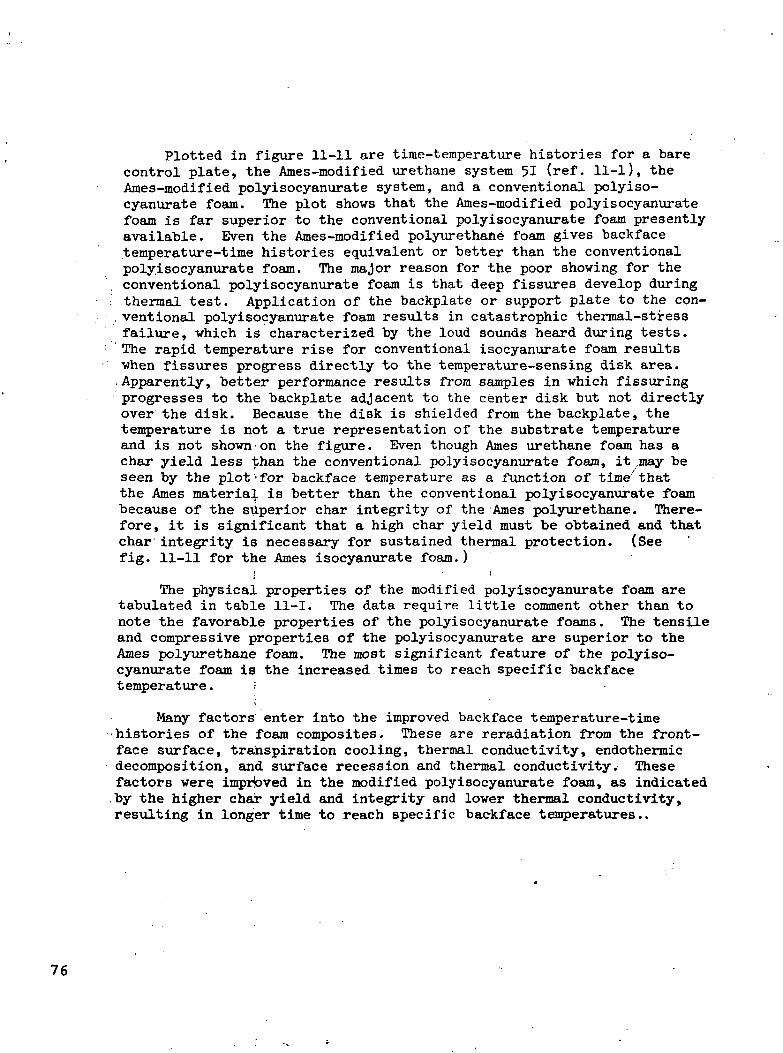
Plotted in figure 11-11 are time-temperature histories for a barecontrol plate, the Ames-modified urethane system 51 (ref. 11-1), theAmes-modified polyisocyanurate system, and a conventional polyiso-cyanurate foam. The plot shows that the Ames-modified polyisocyanuratefoam is far superior to the conventional polyisocyanurate foam presentlyavailable. Even the Ames-modified polyurethane foam gives backfacetemperature-time histories equivalent or better than the conventionalpolyisocyanurate foam. The major reason for the poor showing for theconventional polyisocyanurate foam is that deep fissures develop during
: thermal test. Application of the backplate or support plate to the con-ventional polyisocyanurate foam results in catastrophic thermal-stressfailure, which is characterized by the loud sounds heard during tests.The rapid temperature rise for conventional isocyanurate foam resultswhen fissures progress directly to the temperature-sensing disk area..Apparently, better performance results from samples in which fissuringprogresses to the backplate adjacent to the center disk but not directlyover the disk. Because the disk is shielded from the backplate, thetemperature is not a true representation of the substrate temperatureand is not shown on the figure. Even though Ames urethane foam has achar yield less than the conventional polyisocyanurate foam, it .may beseen by the plot'for backface temperature as a function of time thatthe Ames material is better than the conventional polyisocyanurate foambecause of the superior char integrity of the Ames polyurethane. There-fore, it is significant that a high char yield must be obtained and thatchar integrity is necessary for sustained thermal protection. (Seefig. 11-11 for the Ames isocyanurate foam.)
i • •The physical properties of the modified polyisocyanurate foam are
tabulated in table 11-I. The data require little comment other than tonote the favorable properties of the polyisocyanurate foams. The tensileand compressive properties of the polyisocyanurate are superior to theAmes polyurethane foam. The most significant feature of the polyiso-cyanurate foam is the increased times to reach specific backfacetemperature. ;
Many factors enter into the improved backface temperature-timehistories of the foam composites. These are reradiation from the front-face surface, transpiration cooling, thermal conductivity, endothermicdecomposition, and surface recession and thermal conductivity. Thesefactors were, imprbved in the modified polyisocyanurate foam, as indicated.by the higher chair yield and integrity and lower thermal conductivity,resulting in longer time to reach specific backface temperatures..
76

NEOPRENE-ISOCYANATE FLEXIBLE FOAMS
To achieve a "nonburning" flexible foam system, Ames modified aneoprene-isocyanate foam by adding a halogenated copolymer, "Saran A,"and postcuring the foam to 275P to 300° F to increase char yield; theresulting char yield was 38 percent at 1000° F. These foams were testedballistically in assemblies such as the one ,in use at Wright PattersonAir Force Base (fig. 11-12). The internal reticulated foam is presentto reduce hydraulic "ram effect" and internal ullage explosions. Thecandidate foam is placed outside the cell between a function plate andthe back cell wall. When corrected for off-bore hits, the number offires per round in the flexible foam is reduced to zero.
FLEXIBLE FOAM FIRE BLANKET
A utility thermal blanket using the neoprene-isocyanate flexiblefoam was developed; that is, a 1/2-inch-thick sheet of the flexiblefoam was placed between two sheets of 'asbestos, thus forming a sandwichof foam in asbestos. This blanket could be placed over stockpiledmaterials and afford protection in the event) of a fire. To demonstratethe usefulness of the foam, an ammunition can was wrapped with theblanket (fig. 11-13) and immersed in a JP-U fuel fire. The temperatureof the 50,-caliber ammunition inside the box was monitored, and the re-sults are plotted in fig. 11-1 . The temperature-time history for anunwrapped box also is shown on the same plot'. Longer protection timescould be expected from a blanket draped loosely over boxes of ammunitionthan for a single box wrapped tightly as it was for this test.
CONCLUSIONS
It has been shown that the use of low-density plastic foams can bemodified for use in effective thermal protection systems. Further workin the areas off reduction of flame spread, smoke generation and classi-fication, and tbxic byproducts is continuing.
However, it must be emphasized that the\ effectiveness of many firesuppressant or extinguishing materials lies in the generation of a largequantity of gaseous products. For the most part, these gaseous productsrange from mildly to severely toxic.
77

REFERENCES
11-1. Parker, J. A., Riccitiello, S. R.; Gilwee, W. J.; and Fish, R. H.;Development of Polyurethane for Controlling Fuel Fires in Air-craft Structures. SAMPE J., April/May 1969.
11-2. Riccitiello, S. R.; Fish, R. H.; Parker, J. A.; andGustafson, E. J.: Development and Evaluation of Modified Poly-isocyanurate Foams, for Low Heating Rate Thermal Protection —Preliminary Data. Paper presented at Symposium on Flammabilityof Plastics, Society of Plastics Engineers, New York, May 1970.
11-3. Parker, John A.; and Winkler, Ernest L.; The Effects of MolecularStructure on the Thermochemical Properties of Phenolics andRelated Polymers. NASA TR-R-276, Nov. 196?.
78
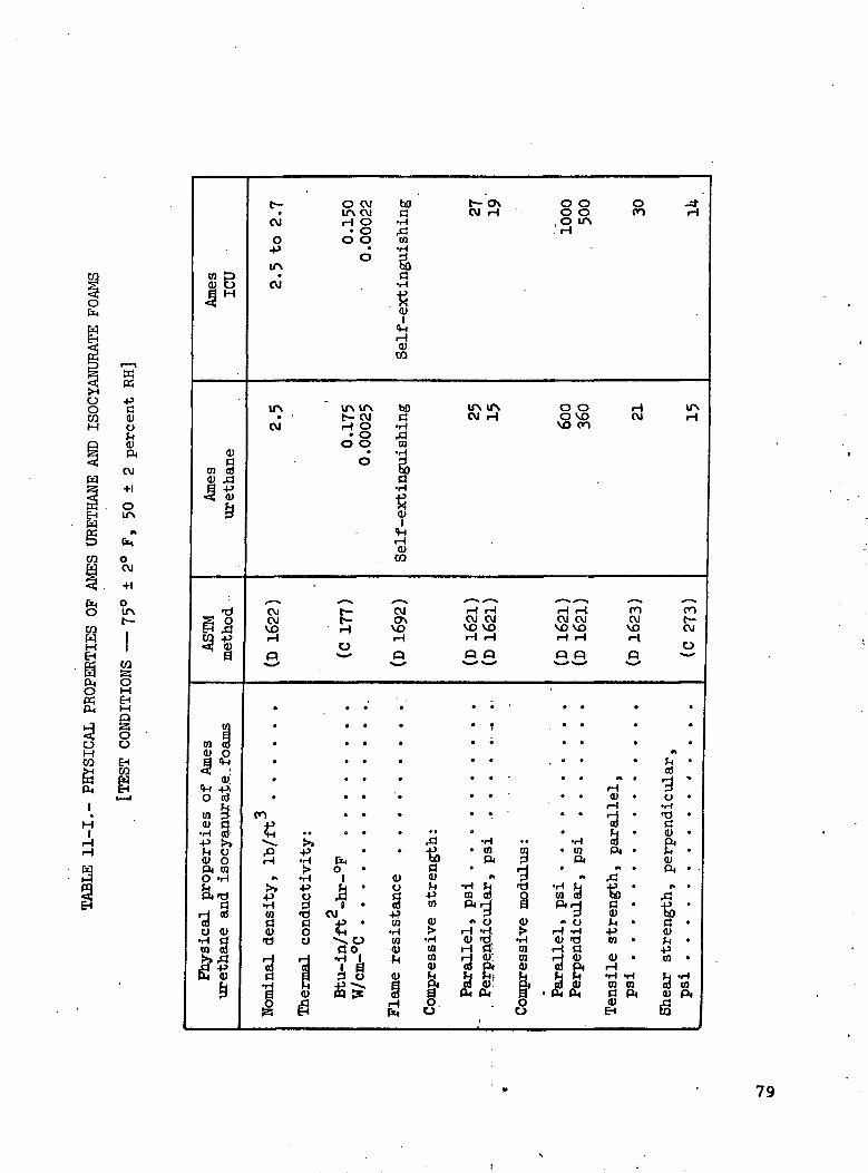
wK
a<voCUPi
CM
+1
OITV
OCM
+1
CO&OM
OO
%
co pCU t)
^
0)a
co a)cy .3||
s o{^ i *^E (j)
S
CO COCU O
cu;
*-r -PiO aj
§ s•H CO•P !»rl O<u oPi COO vH
Physic
al p
r<ure
thane
andt—CM
O-P
CM
ITS
CM
CMCMVOH
3
•
*
.
*
*
mif4-1
i~H
«v
sCOaCU
•c)
Ofe
O CMITV CMH 0• O
O O•
o
ir\ tr\t— CMH 0• O
O 0
o*
t—t—H
O
. • ••. .
. .
. .
• •
• •
-I_* •
•H PC,>• O •
•H 1-P fj •y 33 I ••b CMa +> •O *HO ^x O
florH >H 1
<!> PP frl
^
00a•HfcjCO•H
Si
C•H
0)
H0)
CQ
bOa•H_c^CO•Hg,a
1
rHCU
CO
CMO\
VOH
3
'•'.
.
9
'••
.
CU
ame
resis
tanc
rH
*
£oOaCU
mpre
ssiv
e
str
o.o
t— o\CM H
lf\ ITSCM H
'H "inCM CMVO VOH rH
33
• t
• *
. .
. .
* '
* *.
•H• CQ
Pi
»»
Para
llel, p
si
Perp
endic
ula
r
•
co£jr_j3
mpre
ssiv
e m
od
o0
00 0O O CO
, O IAH
O O HO VO CMVO CO
rH l-i COCM CM CMVO VO VOrH rH rH
33 S
. .
• • .
... .. . « .
rH. . CU .
,_{
; • ^ ;•H CO
• CO Pi •ft
** JtJ
• Para
llel, p
si
Perp
endic
ula
r
nsile
strengt
psi
Q)
H
•H
ITSH
COt—CM
0
•
.
rT •
H »po •
'i •CU •PiCUPi •
ear
str
ength
,psi
iQ
Eo
79

tf\m
mvo vovo coen f-
w p<u o
IfN O 0
tt)ofc0)FM
CVI
+1
O
ifl
Oc\J
ASTM
ethod CM
HOJ
Q
(0 m
II
CO3OME-i
OO
EHCO o o
0) 0 ) 0 )en en
80
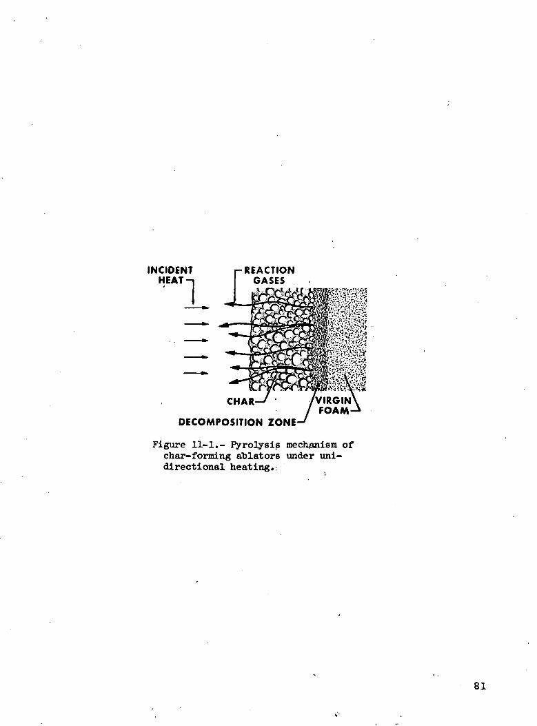
INCIDENTHEAT
REACTIONGASES
CHAR-
DECOMPOSITION ZONE-
Figure 11-1.- Pyrolysis mechanism ofchar-forming ablators under uni-directional heating.:
81
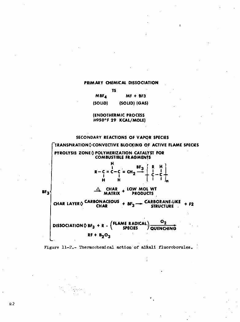
PRIMARY CHEMICAL DISSOCIATION
TSMBF4
(SOLID)
MF + BF3
(SOLID) (GAS)
(ENDOTHERMIC PROCESSH950°F 29 KCAL/MOLE)
BFj
SECONDARY REACTIONS OF VAPOR SPECIES'TRANSPIRATIONQCONVECTIVE BLOCKING OF ACTIVE FLAME SPECIESPYROLYSIS ZONE 0 POLYMERIZATION CATALYST FOR
COMBUSTIBLE FRAGMENTS
I BF.R-C = C-C = CH-—i
IH
IH
RI
HI
- - C -C - -
A CHAR . LOW MOL WTMATRIX PRODUCTS
ruAD |AYPBiSCARBONACEOUS . „. , CARBORANE-LIKECHAR LAYER P CHAR +BF3-~ STRUOURE
niecori ATir»w iN DC 4.0 AFLAME R APICAL \ °2DISSOCIATION l> BF3 * R - ( spEC|K j QUENCH|NG
RF * B203i
Figure 11-2.- Thermochemical action of alkali fluoroborules.

CO2 HCI BF3 H2O
800-1000 °F
600-800400-600 °Ft
70 °F
SUBSTRATE\
DIFFUSION AND THERMALCONTROL SKIN
CHAR ZONE*INORGANIC SALTPYROLYSIS ZONE OF
POLYURETHANE FOAMPYROLYSIS ZONE OF
HALOGENATED POLYMERVIRGIN PHASE
POLYURETHANE FOAMHALOGENATED POLYMER
INORGANIC SALT
Figure 11-3.- Response of Inorganic salt + halo-genated polymeracetate-modified polyurethanefoam to the heating input of a fuel fire.
POLYMER WALL (GELATIN)
FIRE SUPPRESSANT(CI3 C-CF3)
PARTICLE SIZE = 100-300/*
WEIGHT OF ACTIVEINGREDIENT = 85%BY WEIGHT
ACTIVATION TEMP =117-120°F
Figure 11-U.- Encapsulated fire-suppressant particle(microballoon).
83

= N—CH.
CH.CAT
oII
\ / \ .N NI I
o=c c=oNNX
N = C=0(3 MOLES)
Figure 11-5.- Isocyanurate struct\ire.
1.5 r
V/V,
+10 PERCENT
-10 PERCENT
v AMES X-ISO
0 200 400 600 800 1000TEMPERATURE, °F
Figure 11-6.- Dimensional stability in air ofAmes foams.
84

w/wc
}Q
.6
.6
.4
.2
\ AMES X-ISO
AMES 51
0 200 400 600 . 800 1000
TEMPERATURE, °F
Figure 11-7.- Char yield in nitrogen ofAmes foams.
100
80
CHAR 60YIELD,
PERCENT 40
20 -
POLYPHENYLENE
POLYBENZIMIDAZOLE,
AMES X-ISO PHENOLICS
AMES 51
EPOXY-NOVOLAC
0 2 4 6 8 10 12 14
NUMBER OF MULTIPLE BONDED AROMATICEQUIVALENTS PER GRAM
Figure 11-8.- Correlation of primarythermochemical char yield vithmolecular structure.
85

-OILBURNER J
ftasjsasa
TYPICAL HEAT FLUXES
AREA;! 9-16 Btu/FT2-SEC
AREA -2 5.5-11 Bhi/FT2-SEC
AREA 3 -21 Btu/FT2-SEC
COMBUSTION CHAMBER 0 6SCALE, IN.
Figure 11-9.- Ames T3 thermal test facility (JP-U fuel).
TEMPERATURESENSING DISK-
0.0625 IN.ALUMINUM
BACKING PLATE .2 IN. THICK
SAMPLE
0.5 IN.ASBESTOS
EDGE MASK
Figure 11-10.- Sample foam assembly.
86

BACK-FACETEMP, °F400
300
200
100
HEATING RATE = 10 Bty/FT2 SEC
•FIBER GLASS MAT
AMESISOCYANURATE
AMESFIBER-FILLED
URETHANE
10 15 20 25EXPOSURE TIME, MIN
30 35
Figure 11-11.- Performance of various fire-retardantfoams in JP-U fuel fire.
BORELINE TARGET AREA 53 IN. x 7 IN.
VENTRETICULATED
INTERNALFOAM
CANDIDATEEXTERNAL FOAM
J5.S IN. x 155 IN. x .090 IN. Al3 IN.)-, IJFREPl ACE ABLE
PANEL.
.50 API1800-3000
FT/SEC
.090 IN. AlSTRIKER PLATE
/ TANK DIAMETER 16 INVMAXIMUM LENGTH 48 IN
Figure 11-12.- Wright-Patterson Air Force Base testcell-17-gallon capacity tank. .
87

__ /
ASBESTOSWRAPPED
LEAD
FUELSUPPLY
RID SUPPORT
CARTRIDGE CASE WITHTHERMOCOUPLE
.:•:••;-.' Figure 11-13.- Test of foam blanket to protectammunition box. •
TEMPERATURE,BOX WITH
PROTECTIVEBLANKET
2 4 6 8 ; 10 12 14 16TIME AFTER START OF FIRE, MIN
Figure 11-lU.- Time-temperature history of 50-calibercartridge in ammunition box, JP-fuel fire.
88

'•'- INTUMESCENCE: AN IN SITU APPROACH TO
THERMAL PROTECTION
By G. M. Fohlen, J. A. Parker, S. R. Riccitiello, and P. M. SawkoNASA Ames Research. Center
Presented by Dr. John A. Parker at the WESRAC-Fireproofing and SafetySymposium, May 27, 1971, Los Angeles, California
ABSTRACT
The phenomenon of intumescence, the swelling of a substance uponthe application of heat, has been used for many years in the form ofsurface coatings as a means of protecting fire-sensitive building mate-rials. With regard to experience gained at the NASA Ames ResearchCenter in the areas of polymer chemistry and ablation technology'forthermal protection, intumescent systems that may serve to protect avariety of! heat-sensitive components, such as; fuels, explosives, struc-tural materials,! and even man, have been reexamined. In this paper,the evolution of intumesoent coatings from the older carbohydrate-phosphoric acid systems, through the nitroaniline bisulfate salts orig-inally used by N^SA, to the newer nitroaniline-sulfonic acids,quinonedioxime-acid mixtures, and nitroanilinpsulfones, is described.In the case of the nitroaniline derivatives, the intumescence is modeledas a thermal self-polymerization of the'aromatic compounds passing throughplastic states, being expanded by evolving gaseous products to formfinely textured,, low-density foams. These foams have low thermal con-ductivity, high pmissivity", and good resistance to ignition. The gasesthat are evolved during the polymerization reaction and that are injectedinto the fire zone further serve as flame quenchers. The resulting poly-meric foams are polyheterocyclic structures similar to polyquinoxalinesor polyphenoxazipes. The development of several useful coating systemsto effect fire protection in a variety of applications is discussed.Potential applications ranging from the prevention of weapons cookoffto the improvement in the firesafety of building materials areillustrated in simulation tests.
INTRODUCTION
As a result!of the disastrous fires aboard the.Apollo spacecraftand on the aircraft carrier U.S.S. Forrestal in 1967, the attentionof the Thermal Protection Group at the NASA Ames Research Center (ARC),
89

whose previous task was the development of heat-shield materials andthermal-protection coatings for spacecraft, was directed to the study ofprotecting heat- and fire—sensitive materials in general.
One immediate goal was the development of> a means of thermal pro-tection for stored bombs to prevent detonation when the bombs are sub-jected to the heat of burning fuels. This bombs must be protected for atime that is sufficient either to deploy; firefighting equipment or tojettison the bombs. To accomplish this jshort-time thermal protection,it was desired to coat the bombs with a material that would swell, uponheating, to form a thermally resistant insulating layer. This processor phenomenon of swelling with heat is called "intumescence" (ref. 12-1).
Many people are familiar with a forjn of intumescence in the noveltyitem known as Pharaoh's Serpents. Another example of this phenomenon isthe classroom demonstration that is used' to introduce the subject ofcarbohydrate chemistry to college freshmen. Ih this demonstration, thedehydrating action of concentrated sulfuric acid on sugar produces avoluminous amount of black, low-density,) carbonaceous solid.
""".'• ' j >i \The use of the intumescent process in the- form of coatings /to pro-
vide thermal projection for flammable substrates is not new. As anexample, such coatings have been applied) to cellulosic ceiling tilesfor nearly 20 yeaJrs. Early versions of these coatings made use of areaction similar fto the sugar and acid mixture? mentioned previously inthat the coatings; consisted of a mixture'of a carbohydrate, such as starch,as a char-forming material and a dehydrating catalyst, such as ammoniumbisulfate or ammonium phosphate, compounded with a binder. Upon heating,these materials initially released ammonia gas., and the resulting sulfu-ric or phosphoric acid subsequently acted on the carbohydrate to yieldthe low-density, carbonaceous char, formed by the action of the liberatedammonia and steam (ref. 12-2). Continuing efforts by chemical and coat-ing manufacturers.'to improve the intumescent coatings, both in the useas coatings and as thermal protectors, have led to the use of variousother carbonific substances that usually are drawn from the class ofpolyols, such as pentaerythritol and dipentaerythritol. Other gas-producing materials and catalysts, such as ammonium polyphosphate,melamine phosphate, phosphoramide, and dicyandiamide, also have beenused in improved versions (refs. 12-1 to i 12-3). The main drawback tothe use of these previously developed coatings ;has been the lack of long-time stability to;outdoor weathering. This deficiency has limited theuse of those materials to interior or protected environments. What hasbeen needed'is a coating that is able tojwithstand continuous outdoorexposure — conditions of high humidity, rain, twide fluctuation in ambienttemperature, and, for bomb application, exposure to salt spray.
i - iWith the advent of new high-temperature and oxidation-resistant
polymers, such as polybenzimidazoles, polythiazoles, polyphenoxazines,
90

and polyquinoxalines (refs. 12-1| to 12-7), the possibility vas suggestedthat new kinds of char-forming materials might be developed to secureimproved intumescent coating systems with high-temperature resistancethat also would be nonburning, nonsmoking, and nontoxic, if a methodcould indeed be found by which these polymers could be made thermallyand in place. A general and idealized isequence of reactions required toobtain stable heterocyclic polymers (in sufficiently low density to beuseful) formed by the process of intumescence is shown in figure 12-1.The approach for this research was the selection of monomers or prepoly-mers that are stable to at least 300° to 350° F and that thermally reactat temperatures greater than 390° F to give the thermally and oxidativelystable, aromatic, heterocyclic polymers. During the process, the evolu-tion of some and the partial retention of a fraction of the gases thatare byproducts of the condensation polymerization should form a low-density foam in ,situ. As indicated in figure 12-1, the polymerizationreaction must proceed through a molten phase to secure the desired degreeof plasticity during the expansion. To obtain efficient thermal protec-tion, the polymerization and expansion reaction should occur preferablyin the direction of the applied heating. Anojther important requirementof this polymerization process is that a sufficiently high degree ofpolymerization b'e obtained by the time the expansion is completed toobtain a mechanically coherent foam strjicturei that will not collapse.
To secure a low thermal conductivity, the foam obtained by thisprocess should be predominantly closed cell and of low density. Thepossibility should exist to select monomers or prepolymers that polym-erize to give off gaseous byproducts that, in addition to effecting thefoaming of the polymer, can diffuse into the flame boundary to blockconvective heat transfer (ref. 12-1) and interact with and suppressfree-radical chain carriers that are characteristic of the flame-propagation process.
APPLICATION OF THE REACTIONS OF SUBSTITUTEDNITRO-AROMATIC AMINES AS INTUMESCENT MATERIALS
The formation of voluminous, black, spongy foam from the action ofheat on a mixture of sulfuric acid and p-nitroacetanilide had been de-scribed by Alyea (ref. 12-8). In the study made at ARC, a number ofvariously substituted nitro-aromatic amines were examined for intumes-cent properties (fig. 12-2).
As indicated in figure 12-2, the expanded black polymer was formedfrom both o-nitroanilines and p-nitroanilines, as well as from substi-tuted derivatives. These materials gave excellent expansion of 70 to2UO times the original volume. The process was found to occur within
91

a temperature range of 390° to 500° F. Acetylation of the amino groupdid not seem to affect the intumescent process. It was observed quali-tatively that the resultant dark polymeric foam vas extremely resistiveto the erosive action of an intense hydrocarbon gas flame. Originally,the belief was held that this intumescent reaction of nitroanilinescould be caused only with concentrated sulfuric acid; however, subse-quently, it was found that the use of cpncentrated phosphoric and poly-phosphoric acids also promoted the reaction.
The observation of the effect of heat .an,d sulfuric acid onp-nitroaniline led quickly to the development of the associated bisul-fate salt as a dpry compound, which is useful'las an intumescent agent.This compound was prepared easily from inexpensive, readily availablematerials. The preparation and properties of this material are shown infigure 12-3 (refs. 12-9 and 12-10). Upon heating the p-nitroanilinebisulfate to temperatures greater than 'U30° F, a yield of black foam ofapproximately 50 to 5^ percent by weight is obtained that is stable totemperatures greater than 1020° F. , j
To investigate in detail the reactions that occur during intumes-cence, three analytical techniques were used.< Thermogravimetric analysis(TGA) of the weight loss of a sample of p-nitroaniline bisulfate wasmade, elemental ianalysis of the thermally reacted material was obtained,and, in a separate experiment, the kinds of gases produced were deter-mined by gas chromatography. '
An 8-milligram sample of the p-nitroaniline bisulfate describedpreviously was heated in dried, deoxidized nitrogen at a rate of 5«**° Fper minute. The weight loss was determined by means of a Cahn recordingelectro-balance and plotted as a function of sample temperature(fig. 12-1*). The empirical formula for the initial salt can be writtenas shown at the right of figure 12-U. The theoretical weights that cor-respond to the thermolytic process also are shown. Three distinct andsequential reactions can be seen to occur in going from room temperatureto 1*30° F, at whiich point, a sudden intumescence is initiated. Theweight loss associated with each of these thr.ee distinct processes isequivalent, on a mole basis, to the loss of one molecule of water. Thisloss produces a -change in the composition of ;the residue material asindicated in 'the empirical formulas at the right of the thermogram. Thewater produced during this induction phase (that is, before intumescence)does not contribute to the foaming process bu£ rather is injected direct-ly into the adjacent gas boundary. As indicated in the thermogram, intu-mescence occurs at temperatures greater than U50° F with elimination ofsulfur dioxide, and more water is eliminated at ..temperatures greater than600° F. . ; -
92

Chromatographic analysis of the gases eliminated during the intu-mescence confirmed that sulfur dioxide and water, both good flamequenchers, were produced. Elemental analysis obtained on the blackintumesced foam that was formed at U82° F was. obtained as shown infigure 12-5. The analysis indicates that nearly all the sulfur is lostand all the nitrogen is retained.
Coatings were prepared using the p-nitroaniline bisulfate compoundas the intumescing agent. The coatings performed quite well in theproper environment, as will be described subsequently. However, becauseof the nature of the material (a salt of a w ak base and a strong acid),it was easily affected by the presence .of moijsture, giving an extremelyacidic milieu that both affected the vehicle in which it was combinedand corroded metallic substrates upon humid exposure. To circumventthese deficiencies, other intumescing agents were desired that wereneither easily hydrolyzed nor acidic.
One of the primary reactions between su furic acid and nitroanilineis sulfonation of the ring. By keeping mixtures of these ingredients attemperatures below that of intumescence, fair yields of p-nitroaniline-o-sulfonic acid:were prepared, isolated as an almost white powder. Thiscompound was found to intumesce quite easily .at 1*50° F and to give a charyield of 50 percent. The product of intumescence resembles and is similarin analysis to i;he materials obtained from p—nitroaniline bisulfate. Thering sulfonation in this second compound overcame the problem of hydro-lytic stability encountered with p-nitrjoaniline bisulfate, but the prob-lem of acidity remained. It was found rthat the ammonium salt of thissulfonic acid also would intumesce, but- at a bomewhat higher temperature(572° F). This material is prepared easily from the commercially avail-able sodium salt by reaction with ammonium chloride. The TGA of thismaterial is shown in figure 12-6.
The intumes.cent reaction of the p-nitroaniline-o-sulfonic acid, orthe associated ammonium salt, is not discussed in this report. However,the sulfonation .of the aromatic, ring is probably not a necessary stepin the intumescent reaction, and the ring-substituted sulfonic acidactually acts as an in situ source of sulfuric acid when this compoundis heated. Thus, the reaction is similar to that of p-nitroaniline andsulfuric acid.
• • iContinuing -research into the reactions of nitrogenous aromatic
compounds has produced two other intumescent pystems of interest. Thesesystems are bis-'(U-nitroanilino)-sulfone that; intumesces when heatedalone, and p-benzoquinone dioxine that intumesces when heated with con-centrated sulfuric or phosphoric acid. In all these types of intumes-cent reactions, the role of the acid apparently is primarily that ofdehydration.
93
Although, it has been speculated that the polymer formed during theintumescence of p-nitroaniline bisulfate may be a laddered polyquinoxa-line or polyphenoxazine (ref. 12-11), no direct proof has yet beenobtained. The materials obtained in the thermal reaction of all theseclasses of compounds are insoluble in all solvents tried, including con-centrated sulfuric acid. Spectroscopie examinations have been inconclu-sive, and the scissioning reactions tried have, thus far, not yieldedfragments that would aid in structure elucidation. The primary investi-gative means used has been the elemental analysis of the black materialsobtained and has led to the speculation that structures of the productsof the thermal reactions are combinations of recurring units shown infigure 12-7» all derivable from the starting materials by addition, de-hydration, hydrolysis, rearrangement, and ring closure to varying degreesdepending on the temperature to which the material is exposed. Thesestructures are similar to those proposed by Szita and Marvel (ref. 12-12)and Stille and Freeburger (ref. 12-13) for polymers derived from morecomplex starting materials in nonintumescing systems.
COATINGS
Two intumescing agents described in the iprevious section,p-nitroaniline bisulfate and the ammonium salt of p-nitroaniline-o-sulfonic acid, were formulated into practical, useful, coating systems.The key to the successful formulation of these coatings has been theselection of a binder system that does not interfere with the intuaes-cent process, is; compatible with the intumescing agent, and will notcontribute significantly to the flammability of the system. The vehicleshould be either! thermoplastic or easily degraded thermally in the sametemperature range in which intumescence takesi place.
The use of the p-nitroaniline bisulfate salt also required that thevehicles selected as binders be relatively stable to strong acid. Water-based vehicles that are commonly used in paints were also eliminated fromconsideration with the bisulfate salt because of their hydrolytic in-stability. Two vehicles were selected for use with the p-nitroanilinebisulfate: nitrocellulose and a phenolic resin modified acrylonitrile-butadiene polymer. The formulations are given in tables 12-1 and 12-11.The formulation using the ammonium salt of p-nitroaniline-o—sulfonicacid is shown as; U5B3. This material did not, have the rather strictlimitations of vehicle selection as with the first salt, because it isneither acidic nor hydrolytically unstable. These coatings were pre-pared by common paint-making techniques and were suitable for conven-tional brush or spray applications. The air-dried coatings had goodinitial properties.
94

TESTS AND POSSIBLE APPLICATIONS OF COATINGS
Measurements in a typical JP-U fire with free convection showedthat heating rates applied to surfaces immersed in such fires are approx-
2imateQy 30 000 Btu/hr/ft , approximately 90 percent in the form of radia-tion. This fact made it possible to run screening tests on candidateintumescent coatings in the beam of a solar simulator (fig. 12-8) that
ois capable of the delivery of 30 000 Btu/hr/ft to a 2-inch-diameterspecimen at a distance of approximately U inches from the focus.
This arrangement was used to screen various thicknesses of the in-tumescent coatings described previously. The spectral distribution ofthe solar simulator beam, which has its peak in the visible portion ofthe spectrum, did not match that of the JP-U fire, which peaks at approx-imately 2.5 microns; however, the thermal-protection process appears tobe independent of this difference in spectral distribution.
Intumescent coating formulation 3Ul was applied in thicknesses fromapproximately 0.007 inch to approximately 0.065 inch on a 0.060-inch-thick cold-rolled steel substrate. The test specimens, which were 1 inchin diameter, were surrounded by thermal insulation to eliminate edgeeffects, and a thermocouple was mounted on the backface to provide thetime-temperature history.
The test of an intumescent coating specimen in the solar simulatorbeam is more severe than a JP-U fire for two reasons. Although the aver-
• . oage heating ratfe at the surface is 30 000 Btu/hr/ft , the intumescencecauses the surface to grow outward toward the focus where the heatingrate is higher.; Furthermore, there is,a radial energy gradient in thebeam, and the irradiance is slightly higher on axis than the averagevalue over the area of the test specimen.
A history of the substrate backface temperature during the test inthe solar simulator is shown in figure 12-9. '' The bare metal without thecoating reached;U00° F in approximately 20 seconds. On a similar metalsubstrate with the intumescent coating, the intumescence began withinapproximately 10 seconds and was nearly complete within 20 seconds.
The thermal insulation provided by the intumescence caused a muchslower temperature rise of the metal substrate. The increasing slopethat.occurred later shows the effect of the intumescence growing closerto the focus of the solar simulator, where it experiences a much higherheating rate.
95

The results of numerous tests in the solar simulator beam and inJP-k fires are given in figure 12-10. These results show how the timerequired for the substrate to reach a given temperature varies withintumescen£ coating thickness. Temperatures of 300° and kOO° F werechosen as limits, for presenting these data. The relationship is linear,as might be predicted, because the thickness of the intumescence afterheating is directly proportional to the thickness of the coating beforeheating. As can be seen in figure 12-10, the. times to reach 300° andU00° F are shorter for the solar simulator tests than for the fuel fires,demonstrating the greater severity of the solar simulator tests.
The fact that the coating formulation 3 1, using nitrocellulose asthe binder, intumesces to give a thick, stable, closed-cell polymer thatis highly resistant to heat leads immediately to the possibility of itsapplication in such places as an airplane where fuel lines or hydrauliclines exist in fairly restricted volumes. A fire in such a locationwould be extinguished if the intumescence filled the available volume.To test this, a simulated section of fuselage was built, and two 2-inch-diameter tubes (simulating fuel lines) i ere installed through holes inthe section. Th£s test setup (fig. 12-il) was 12 inches wide and.5-1/2 inches deep. The ends and one side of this box were sprayed onthe inside|With ihe intumescent coating !to a thickness of O.OUO inch.A fuel pan j containing 200 cubic centimeters of JP-U was placed tinder thebox, and the fuel was ignited. The fire caused the intumescent coatingon the surface to fill the available volume, thus extinguishing the firebefore 30 cubic centimeters of the fuel had been consumed.
• IBecause of the nature of the p-nitrpaniline bisulfate salt and its
high loading in formulations 3Ul and UlO-lA, these coatings did not re-tain good properties upon long exposure ito humid environments. Theacidity of this salt caused corrosion of metallic substrates and deteri-oration of the vehicles. However, in certain controlled or protectedenvironments, or iif suitably protected by a top coating, the coatingshave great utility as Just described. ;
iThe intumescent coating, formulation **5B3, is composed of the ammo-
nium slat of p-nitroaniline-o-sulfonic acid dispersed in a binder composedof equal parts of a polysulfide polymer !and an epoxy resin. After appli-cation, the| coating has a hard, glossy, abrasion-resistant surface. Ithas good adjierende to the substrate,
iThe coating has been tested for its effectiveness in protecting a
structure from fire. The heating of a l/l6-inch-thick steel plate withand without the protection of the coating is shown in figure 12-12. Thetests were made in a specially constructed furnace that exposed thesamples to a controlled JP-k fire. With no protection, the temp'eratureof the plate rose' to U00° F in less than 1 minute. When the plate was
96

protected vith an 80-mil-thick coating, the heating of the plate to1*00° F was delayed for 5 minutes.
The effect of a high-humidity, high-temperature environment on thethermal performance of the coating has been measured. The results ofthis test also are shewn in figure 12-12. The temperature history of acoated steel plate that had "been exposed for 30 days to high humidity(90 percent) at a temperature of 100° F is compared with the temperaturehistory of the coated plate that had been conditioned in the laboratoryatmosphere (50-percent humidity, 73° F.). The comparison shows that ex-posure to the humid environment had no significant influence on thethermal protection afforded by the coating. The small difference be-tween the curves is within the limits of experimental reproducibility forthis test.
Samples of the coating also have been exposed for a 90-day period tothe natural weather conditions on the roof of the laboratory. Coatingsamples on 3- by 6-inch steel plates were placed at a 5° angle abovethe horizontal, facing south. During the period of exposure, approxi-mately 9-7 inches of rain fell. The coating was darkened by the expo-sure, but its intumescence was not affected. Figure 12-13 is aphotograph comparing an exposed test sjample with a control sample, bothof which were heated in an oven to complete intumescence following theexposure. No important difference in ;the intumescent characteristics ofthe two samples is evident. The coating thus shows good stability underhumid environments for at least a 10-day period. Two environmentaltests are continuing.
A slightly modified version of the U5B3 formulation was applied toa simulated bomb casing consisting of a section of 5-inch pipe with1/ -inch wall thickness. The time for the interior wall of the pipeto attain a temperature of U00° C, the critical temperature for theexplosive charge, was approximately 8 minutes. The time for an uncoatedsection of pipe to reach the same temperature was approximately 30 sec- .onds. The intumesced coating appeared to have acceptable char integrityand adhesion, hich were better than other coatings tried. A full-scaletest using 5004pound bombs is currently in progress.
Many applications of intumescent coatings are possible; for example,on electric motor casings; in fuel and< chemical plants and tank farms;and on engine canopies, ventilator grids, and building exteriors. At thepresent state of development, it is not recommended that these coatingsbe used in populated or unventilated areas because of the quantities ofsulfur dioxide released.
Preliminary specifications for the various coating systems havebeen established and are available from NASA headquarters.
97

A research, contract has been let to study further intumescent coat-ing systems, especially the relationship of the properties of severalclasses of polymers as vehicles, in combination with certain selectedNASA-developed intumescing agents. The influence of polymer type,cross-link index, glass transition temperatures, and other propertieson the intumescent process is expected to result from such a study.
Other ongoing research within NASA will'study the chemistry ofintumescence and the synthesis of other intumescing agents, with theobjectives of developing materials more suitable for use in viableenvironments and developing a range of activation temperatures. Anotherpossible result is the use of the intumescent materials as an inexpen-sive, refurbishable, heat-shield material.
ACKNOWLEDGMENT
The authors wish, to acknowledge the assistance of Dr. A. C. Poshkus,who prepared the ammonium salt of p-nitroaniline-o-sulfonic acid undera NASA-National Research Council Resident Research Grant, under thedirection of Dr. John A. Parker.
98

REFERENCES
12-1. Hindersinn, R. R.; and Wagner, G. M.: Fire Retardancy.Encyclopedia of'Polymer Science and Technology, Intersci. Pub.,1966, pp. 13, 36.
12-2. Anon.: Fire Retardant Paints. Advances in Chemistry, vol. 9,Am. Chem. Soc. , 1951*-
12-3. Vandersall, H. L.: Fire-Resistance Through Phosphorus-CatalyzedIntumescence. Monsanto Co. Res. Dept. , St. Louis, Mo.
12-U. Lena, R. W.: Organic Chemistry of Synthetic High Polymers.Intersci. Pub., 1967, pp. 112, 120.
12-5. Stille, J. K.; and Williamson, J. R.: Polyquinoxalines.J. Polymer Sci., vol. A2, 196H, p.-3867.
12-6. Stille, J. K. • Williamson, J. R.; and Arnold, F. E.:Polyquinoxalines. II. J. Polymer Sci., vol. A3, 1965,pp. 1013-1030.
i
12-7. Frazer, A. H.: High Temperature Resistant Polymers, Intersci.Pub., 1968.
r
12-8. Alyea, H. N.: Tested Demonstration in General Chemistry.J. Chem. Ed., vol. 3, no. k, 1956, p. 15A.
i12-9. Arppe, H.: Annalen der Chemiel Vol* 93, 1855, p. 361*.
?12-10. Oddo, G.; and Scandola, E.: Zeitschrift fur Physik, Chemie.
voij.. 66, 1909, p. 1 3.
12-11. Parker,;J. A.; Fohlen, G. M.; Sawko, P. M. ; and Griffin, R. N. :The Use of a Salt of p-Nitroaniline as a Component forIntumescent Coating. SAMPE J., Aug.-Sept. 1968.
12-12. Szita, J.; and Marvel, C. S.: Polymers Derived from 2,5-Diamino-p-Benzoquinone-Diimide and Related Compounds. J. Polymer Sci.,vol. 7, pt. A-l, 1969, pp. 3203-3217.
! I
12-13. Stille, J. K.; and Freeburger, M. E;: Ladder Polyphenoxazines.J. Polymer Sci., vol. 6, pt. A-l, 1968, pp. 161-169.
99
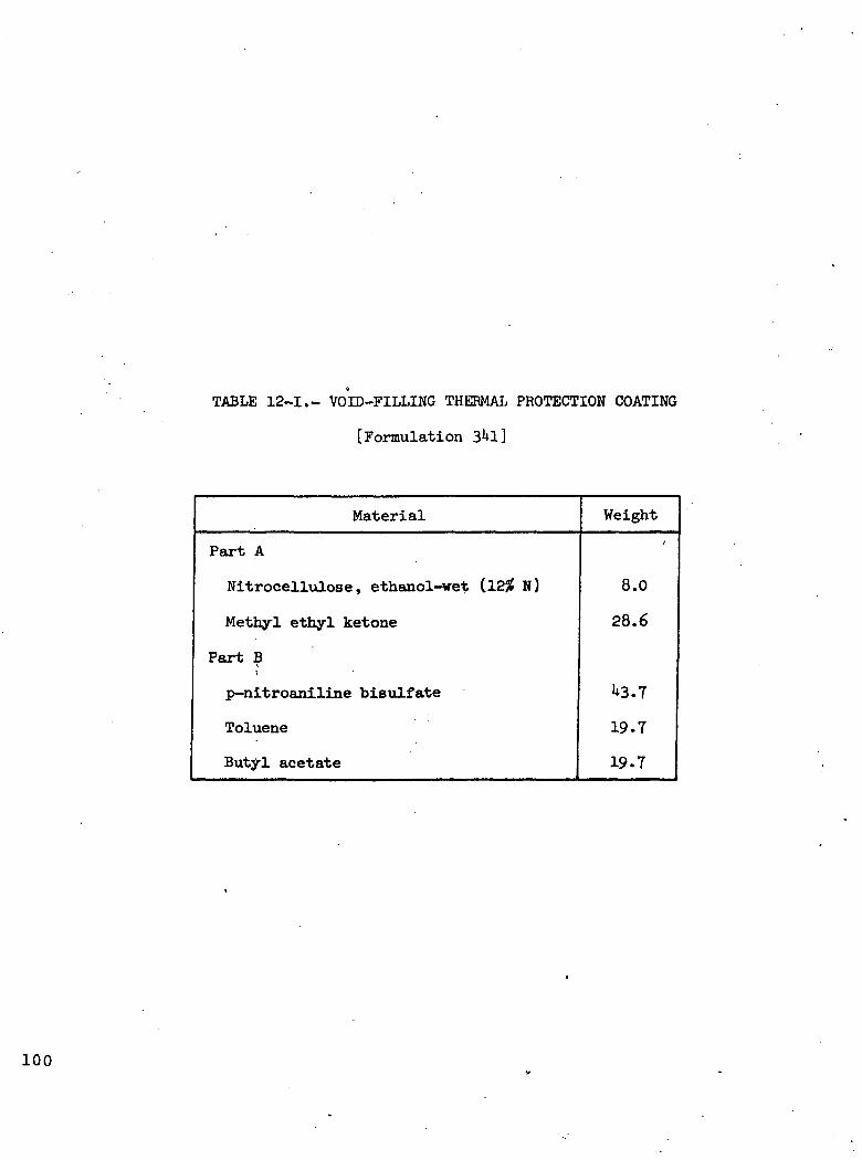
TABLE 12-1.- VOID-PILLING THERMAL PROTECTION COATING
[Formulation 3hl]
Material Weight
Part A
Nitrocellulose, ethanol-wet (125? N)
Methyl ethyl ketone
Part Bi
p-nitroaniline bisulfate
Toluene
Butyl acetate
8.0
28.6
U3.7
19.7
19.7
100
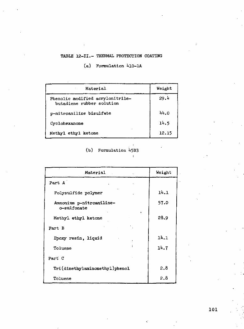
TABLE 12-11.- THERMAL PROTECTION COATING
(a) Formulation UlO-lA
Material
Phenolic modified acrylonitrile-butadiene rubber solution
p-nitroaniline bisulfate
Cyclohexanone
Methyl ethyl ketone
Weight
29. u
Ul+.O
12.15
(b) Formulation U5B3
Material Weight
Part A
Polysulfide polymer
Ammonium p-nitroaniline-o-sulfonate
Methyl ethyl ketone
Part B
Epoxy resin, liquid
Toluene
Part C
Tri(dimethylaminomethy1)phenol
Toluene
1U.1
57.0
28.9
1U.1
1U.T
2.8
2.8
101

STABLE SOLIDMONOMER OR
PREPOLYMER
FOAMING ANDEXPANSION OF
POLYMER INDIRECTION OFAPPLIED HEAT
THERMALPOLYMER-IZATION
> 392° F
HEAT STABLE EXPANDINGPOLYMER GASES
(MELT PHASE)
FOAM
LOW DENSITY
CLOSED CELLCOHERENTTHERMALLY
AND OXIDA-TIVELY STABLE
GAS
EXCESS GAS-EOUS SPECIESINJECTED INTOVAPOR PHASE
CONVECTIVEPROTECTION
QUENCHINGFLAME SUP-
PRESSION
Figure 12-1.- General sequence of reactionsproducing intumescence.
THERMALPOLYMERIZATION
PROCESSOCCURS WITH:
o-NITROANILINE
p-NITROANILINE
p-NITROACETANILIDE
5-NITROISATOICANHYDRIDE ETC
>392° F
CONCENTRATEDSULFURIC OR
POLYPHOSPHORICACID
SPONGY BLACKPOLYMERIC FOAM
GAS
Figure 12-2.- Intumescent reactions of substitutednitro-aromatic amines.
102

1.0
NH2i
NO
NH3 (HS04)'
H2SO4(CONC)
p-NITROANILINE
NO2
p-NITROANILINE BISULFATE
293° F ______ MELT POINT ______ 392° F (DECOMP)138 ___________ MOL WT _______ 236 (CALCULATED)
236 (MEASURED)YELLOW SOLID— APPEARANCE _______ LT YELLOW SOLID
/ SOLUBLE IN ALCOHOLS, \KETONES INSOLUBLE IN
\BENZENE, TOLUENE, ETHER/
Figure 12-3.- Synthesis and characterization ofintumescent intermediate p-nitroanilinebisulfate. »•
WEIGHTFRACTION
REMAININGTHEORETICAL
WEIGHTEMPIRICALFORMULA
.50— C6(H20)N2
424
LOSS
C6(H20)4(S02)N2 .6(H20)3(S02)N2 £20
C6(H20)2(S02)N2 ( "2W
SO2
H2O
-REGION OFINTUMESCENCE
(C6H3Nl.80S.i4)
400 800 1200TEMPERATURE, °F
EMPIRICAL ELEMENTALANALYSIS OF FOAM AT
52% CONVERSION
Figure 12-U.- "Typical TGA of p-nitroaniline bisulfate(5.1*0 F/min in N2).
103

C
59.65 2.51
N S O
20.77 3.64 13.43%
WHICH CALCULATES TO GIVE AN EMPIRICAL FORMULA:
C6 H3 N1.8 .14
Figure 12-5.- Elemental analysis of "black intumescedpolymeric foam formed from p-nitroaniline bisulfateat U82° F.
5.4° F/MIN IN N2
1.0
WEIGHTFRACTION
REMAINING .5
0 200 400 600 800 1000 1200TEMPERATURE, °F
Figure 12-6.- The TGA of p-nitroaniline-o-sulfonic acid,ammonium salt (5-1*0 F/min in flU).
104
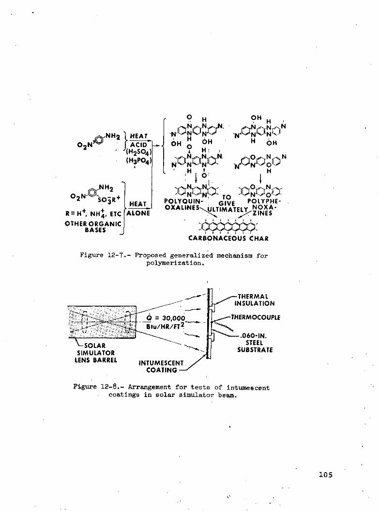
O2N\ HEATI ACID''(H2S04}(H3P04)
R=H+ NHj, ETC
OTHER ORGANICBASES
HEATALONE
H
OH"
OH
POLYQUIN-
OH
H OH
H
POLYPHE-
CARBONACEOUS CHAR
Figure 12-7.- Proposed generalized mechanism forpolymerization.
_ = 30,000Bto/HR/FT2
- SOLARSIMULATOR
LENS BARREL ,NTUMESCENTCOATING
THERMALINSULATION
THERMOCOUPLE
.060-IN.STEEL
SUBSTRATE
Figure 12-8.- Arrangement for tests of intumescentcoatings in solar simulator beam.
105
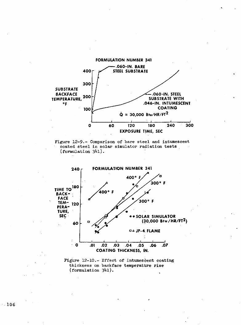
400
FORMULATION NUMBER 341
•.060-IN. BARESTEEL SUBSTRATE
300 -SUBSTRATEBACKFACE
TEMPERATURE,°F
200 -
100
.060-IN. STEELSUBSTRATE WITH
.046-IN. INTUMESCENTCOATING
6 = 30,000 Btu/HR/FT2
60 120 180 240EXPOSURE TIME, SEC
300
Figure 12-9.- Comparison of bare steel and intumescentcoated steel in solar simulator radiation tests(formulation 3^1). '.
240
TIME TOBACK-FACETEM-PERA-TURE,SEC
60
FORMULATION NUMBER 341
400° F,
• •SOLAR SIMULATOR(30,000 Bfu/HR/FT2)
JP-4- FLAME
0 .01 .02 .03 .04 .05 .06 .07COATING THICKNESS, IN.
Figure 12-10.- Effect of intumescent coatingthickness on backface temperature rise(formulation 3kl).
106

Figure 12-11.- Test setup of simulated fuselagesection coated with void-filling thermalprotection coating (formulation 31*!).
HEATING RATE IN JP-4 FIRE = 10 Btu/SEC/FT2
80-MIL COATING ON 0.125-IN. STEEL SUBSTRATE500 r
400 -
BACKFACETEMPERA-TURE, °F
*—NO COATING
CONDITIONING AT 73° F,50-PERCENT RELATIVE HUMIDITY
30-DAY EXPOSURE AT 100° F,90-PERCENT RELATIVE HUMIDITY
Figure 12-12.- Fire-protective effectiveness of 145B3intumescent coating.
107

E HO IN. RAINFALL)
?~ >
^vsr- -^ :;' r>vVr.ry:'>-:'<• ,-\ -•; >>* »w ••.••'. -vv ''•'.••-•J--t\ ..,.•.' i ^ . . • • :
Q ^O
INCHES 2
0
t. -•' 1
i
_ !_[ j
Figure 12-13.- Intumescence of U5B3 coating after 90-dayexposure to outdoor environment (coating thickness^0 miles.)
108
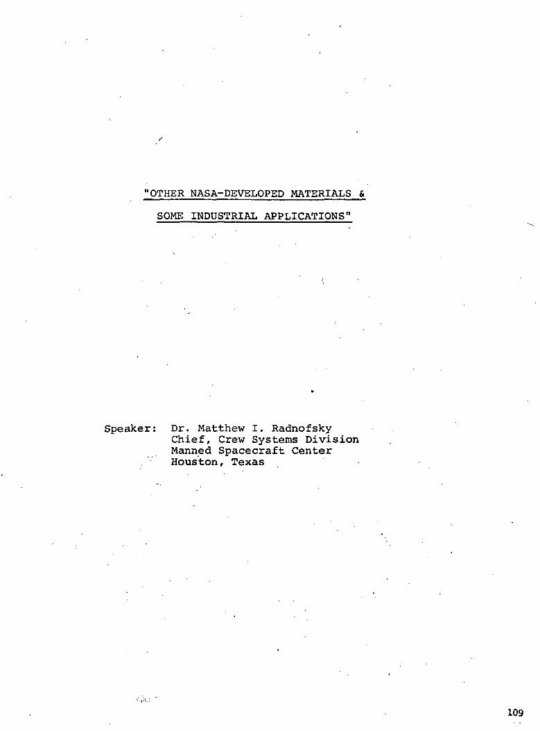
"OTHER NASA-DEVELOPED MATERIALS &
SOME INDUSTRIAL APPLICATIONS"
Speaker: Dr. Matthew I. RadnofskyChief, Crew Systems DivisionManned Spacecraft CenterHouston, Texas
109

Dr. Matthew Radnofsky ,
Chief, Crew Equipment Branch
Manned Spacecraft Center
Houston, Texas
As Chief of the Supporting Development Branch of Crew
Systems Division, Dr. Radnofsky is responsible for all work in
the nonmetallic materials substitution program for Apollo
crew provisions and in support of such other programs requiring
materials development. After the Apollo explosion in 1967,
Dr. Radnofsky headed up NASA's massive research and development
effort in the areas of fire prevention and protection.
Dr.'Radnofsky served from 1961 to 1966 as Assistant Chief
of the Apollo Support Office and as the Systems Manager for
the Apollo Suit Program, Crew Systems Division, where he was
responsible for monitoring Apollo Suit Programs. In July, 1966
he transferred to NASA Headquarters as Senior Systems Scientist
with the Office of Manned Space Flight where he worked on
advance missions analysis in the areas of materials and human
engineering.
Dr. Radnofsky received both his Bachelor's degree in Physical
and Biological Sciences, and his Master's degree in Physiology
from Boston University„ In Mar, 1967, he was awarded an honorary
doctorate-from the University of Taiwan„
111

MATERIALS THAT WON'T BURN
A PRODUCT OF SPACE RESEARCH WITH NONSPACE APPLICATIONS
by
M. I. Radnofsky E. W. Gaulclir.
- One of the prime goals of the manned space program is, and always
has been, to make NASA-sponsored technology available for the general
benefit of an earth-bound populace. It is a goal of which you may be
only dimly aware--but let us hope that at the conclusion of these
remarks, you will join with us in enthusiastically seeking new appli-
cations for space age materials and technology.
Since the inception of the manned spaceflight. program, NASA has
been actively engaged in a search for nonflammable materials to be
used within the spacecraft. This NASA search,- conducted with the
assistance of industry, had led to a progression from the relatively
unsophisticated flameproof materials available ten years ago to the
great variety of fibers, cellulosics, elastomers, and composites which.1 '••
can now be fabricated into nonflammable or fire-retardant end items.
The ability to fabricate has, of course, necessitated the develop-
ment of a technology capable of evaluating and properly utilizing the
specialized materials now available. With this technology in hand, we
believe that many of the nonflammableJ-SLhd fire-resistant materials
developed for spacecraft usage can, when properly adapted, make a
significant contribution to the industrial, construction, transportation
industries, to the public services, and to domestic and institutional
concerns. •
We have made a small, but we believe significant, step by carving
out several small slices of this large pie for special attention; fire
suits and protective garments, aircraft refurbishment, and housing
modular fireproof testing. Each of these programs will be discussed
in some detail in this paper.: i'
'It is, of course, necessary in any evaluation and test program of
this type to know first of all what nonflammable materials are available,
then to assess their properties, and finally, to choose those materials
with properties, including cost and availability, most applicable to
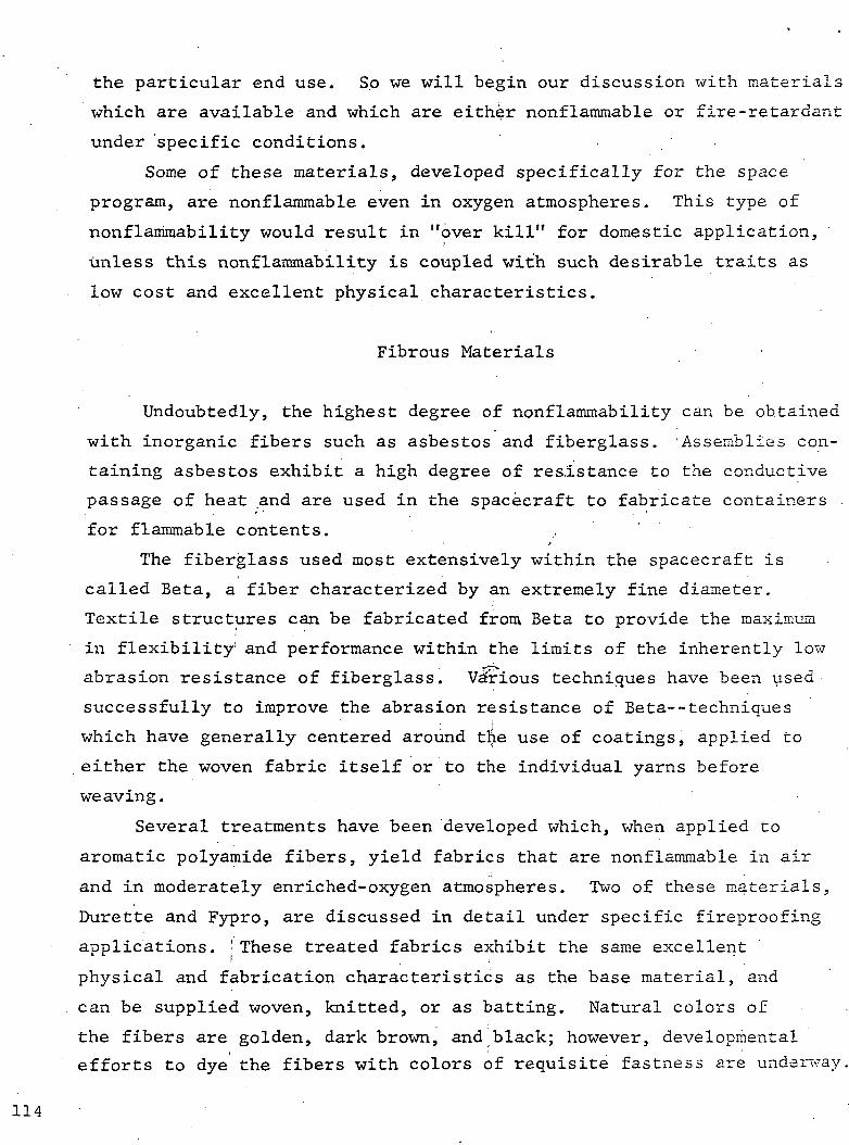
the particular end use. So we will begin our discussion with materials
which are available and which are either nonflammable or fire-retardant
under specific conditions.
Some of these materials, developed specifically for the space
program, are nonflammable even in oxygen atmospheres. This type of
nonflammability would result in "over kill" for domestic application,
unless this nonflammability is coupled with such desirable traits as
low cost and excellent physical characteristics.
Fibrous Materials
Undoubtedly, the highest degree of nonflammability can be obtained
with inorganic fibers such as asbestos and fiberglass. 'Assemblies con-
taining asbestos exhibit a high degree of resistance to the conductive
passage of heat .and are used in the spacecraft to fabricate containers
for flammable contents. .,
The fiberglass used most extensively within the spacecraft is
called Beta, a fiber characterized by an extremely fine diameter.
Textile structures can be fabricated from, Beta to provide the maximum
in flexibility' and performance within the limits of the inherently low
abrasion resistance of fiberglass. Various techniques have been used
successfully to improve the abrasion resistance of Beta—techniques; i
which have generally centered around the use of coatings, applied to
either the woven fabric itself or to the individual yarns before
weaving.
Several treatments have been developed which, when applied to
aromatic polyamide fibers, yield fabrics that are nonflammable in air
and in moderately enriched-oxygen atmospheres. Two of these materials,
Durette and Fypro, are discussed in detail under specific fireproofing
applications. : These treated fabrics exhibit the same excellent
physical and fabrication characteristics as the base material, and
can be supplied woven, knitted, or as batting. Natural colors of
the fibers are golden, dark brown, and.black; however, developmental
efforts to dye the fibers with colors of requisite fastness are underway.
114
A phenolic-type fiber called Kynol, which retains its whole
identity when exposed to flame temperatures up to 2500°F, has recently
been developed. This fiber was originally used mostly as felts and
battings, but spinnability has been improved to the extejit that conven-
tional knitted and woven fabrics are now available. Suits made from
these fabrics have been demonstrated to be highly protective, outer
garments for firemen and race drivers.
A more recent candidate is a fire-retardant wool (treated v/ith a
chemical process called Proban) which meets many of the characteristics
desirable for aircraft and other vehicle interiors. This material does
not burn in air, is available in a wide range of colors, and can be
considered for any application in which wool is a potential candidate.
A similar process, called THPC, is used to impart fire-retardant
qualities to cotton and cotton-based fabrics.'
For purposes of completeness, several materials that are used in
the spacecraft but are not presently considered for domestic applica-
tions are discussed briefly. Polybenzimidazole is an excellent fabric
from almost every point of view,, including nonflammability, but it is
presently comparatively expensive. Teflon fabric is nonflammable, but
has unsatisfactory drape and low tensiLe strength. Metallic fibers are
expensive and lack durability. A new fabric from German Enka closely
simulates cotton and is nonflammable, but as yet, is available only in
experimental quantities.
Nonflammable Paper and Paperboard
A cellulosic material, .developed by the Scheufelen Paper Company
of Germany and processed primarily as a paper, carbonizes in the
presence of a flame but does not propagate the flame. This non-
flammable characteristic is evident both in air and oxygen-enriched
atmospheres. This paper lends itself well to printing and, with some
minor exceptions, has physical properties that are comparable to con-
ventional paper.
115

This paper can be processed into a continuous roil of 0.5 inch
thick foam, similar to papier-mache. When placed on a ceiling, for
example, the foam has both the appearance and function of conventional
acoustic tile and offers the additional advantage of nonflammability.
In addition to the Scheufelen paper, a process called Laminite
which treats cellulose-base fiberboard with ammonium aluminum sulfate
has been evolved. The resultant material is minimally flammable in
oxygen and nonflammable in air. It can be formed wet, coated, cemented,
and joined like a composite; yet, it is lightweight and inexpensive.
Elastomers
Elastomers developed for the space program are fluorocarbons,
basically copolymers of hexafluoropropene and;vinylidene fluoride.
Although the elastomers are themselves minimally flammable, through
the judicious use of compounding ingredients_and plasticizers, non-
flammability and a wide range of physical properties has been achieved.
Notable among these elastomers are Fluorel (developed by the Minnesota
Mining and Manufacturing Company and available from the Mosites Rubber
Company and Raybestos-Manhattan Incorporated) and Viton (developed by
E. I. duPont de Nemours and Company (DET Pont)). The compounded
elastomers can {be foamed, cast, molded, or extruded. The materials
can also be applied as a paste, a coating, or a spray solution.
Mineral pigments in a wide variety of colors can be formulated
into fluorocarbon-based paints. Panels" fashioned of elastomer-backed
nonflammable paper, to which decorative; patterns have been applied,
have been manufactured. The inclusion of asbestos in the backing
provides insulating properties. Such a= lightweight, fireproof sandwich
affords much flexibility in decorative panel design. Elastomeric
coatings can be applied to polyurethane foams and to cellulosic materials•j
such as paper, wood, and sponge, thereby effectively fireproofing the
materials for structural and insulative applications.
116

The capability for coating or replacing electrical components and
accessories with Fluorel has been developed and has been used to some
extent in the space program. The material can be molded to form wire
ties, conduits, circuit breakers, and electrical connectors. When
mixed with asbestos for increased nonflammability in oxygen atmospheres,
the Fluorel can be applied as a conformal coating over electrical parts.,
presenting a firebreak in case of ignition from electrical sources.
Foams
There has been much activity in the area of nonflammable insulating' ' ;
foams. An asbestos foam has been developed by the Rex Asbestos Works• • 1 :
of Germany. This material is marketed in batting and sheets, is inex-:
pensive, and should be useful for general insulation applications. -
The Monsanto Corporation has developed a polyimide foam; however,
it is considerably more expensive than asbestos. The Scott Paper, . ^ .
Company developed Pyrelle foam, a polyurethane with good weight-to-i i
thickness ratio. This material is also inexpensive and commercially
available. They have recently improved upon this product with a
"Super-Pyrelle" which exhibits improved nonflammable properties, while
retaining good physical characteristics.
A definite need exists for an insulation material which can bei , '. .foamed in place. The Avco Corporation has developed, under NASA
contract, an isocyanurate foam which is nonflammable in air atmospheres.
Although easy to apply, this material 'is, at the present time, expen-t • -
sive. The Ventron Corporation has developed a glucose-based polymer
which can also be foamed in place, which is self-extinguishing in air,( ;
and which is extremely low in cost.
The DuPont Company is developing 'a high resiliency polyurethane
foam which can be foamed in place, and which is nonflammable in air.
Potential for use of this foam looks good. This company has also
developed a polyimide and mica paper-like material which foams,and
forms a hard char when heated. This material may have application for
sealing metallic ruptures in the event' of an externally caused fire.
117

Plastics
For replacements in areas where molded plastics are used, KASA,
in conjunction with industrial sources, has developed a number of
nonflammable substitutes. The Whittaker Corporation has developed a
nonflammable polyquinoxalate, and North American Rockwell has developed'*
a polyimide with Du Pont. These materials are at the present time1
expensive; however,, as the more obvious applications are exploited, the
cost should become more competitive with commercially available plastics.
Specific Applications
While these are the more promising candidates, they are by no
means all of the materials which can be. used to coat or replace flammable
components. Additional materials and new ,and advanced technology become
available every day. Working with these materials, we at NASA, in
conjunction with a number of leading material and coating manufacturers.,
have developed methods and material combinations keyed to specific
flameproofing applications.
Ceiling and WalUPPanels
Existing ceiling and wall panels have been coated with Fluorel-
impregnated fiberglass, with an overlay coating of transparent Kel-F
applied for soil and stain resistance. The Fluorel surface can bej ' i •:
furnished in an array of decorative designs. Panel backs have been(
coated with a mixture of 75 percent Fluorel/25 percent asbestos to'. '
prevent heat transfer as well as to provide fire protection.
This technique is applicable to wall and ceiling panels of all
types; although, in the interest of expediency, it is believed to be
more practical ,to supply the Fluorel/fiberglass/Kel-F combination for
direct adhesive application to the panels. Pigmented Fluorel can also
be applied directly to existing panels as a paint to provide fire-
proofing qualities to interior wall surfaces.LI3
Another approach is the replacement of existing ceiling panels
with new panels, fabricated completely.from nonflammable'materials.i ^
To achieve this end, we are taking two ,'approaches--corrugated boards
and a honeycombed composite structure.
The Laminite Corporation is. involved in the development of a
nonflammable corrugated board. The feasibility of this approach has
been demonstrated and we, together with Laminite, are presently working
toward improving the physical characteristics, including weight reduc-
tion. We are also experimenting With a number of different techniques
for applying a decorative finish to the panel surface.
The Hexcel Corporation has been concerned with the development of
a nonflammable honeycomb structure. This honeycomb will be sandwiched
between two nonflammable "skins," with the exterior skin surface
decorated and protected against soil and staining. A number of candi-
date materials, such as fiberglass' Nomex, -and aluminum are being consid-
ered for honeycombing to achieve optimum physical properties. We are
striving for the ultimate in panel construction, seeking panels which
are light in weight, insulative, nonflammable, and exhibiting good
strength, durability, and acoustical properties.
Interior Furnishings
NASA has developed a 20-mil Fluorel sheet, backed with Burette!
knit, to simulate a leather-like finish. This material can be made
porous by a special process called "poralating" to impart "breathe"
qualities to the material. This material is completely nonflammable,
durable, and available in almost any desired color. It is intended fori • . • ' • • . ' • • '
such uses as fabricating chairs, headboards, toilet kits, back covers,
or in any other area where leather or naugahyde-like materials are used.
To fill the need .for upholstery fabric,, a number .of airline's have
switched to Proban-treated woolens. This treatment does not adversely .
affect the wool, but enables the treated woolens to meet Federal
Aviation Agency flammability regulations. This material, available in
119
a wide array of. decorator colors and weaves, has equal application for
any interior refurbishment. In addition to the wool, any of the treated
fabrics, such' as Durette and Fypro, are available in weights and weaves
such as to make them likely candidates for upholstery fabrics. To
illustrate such an application, the Monsanto Company, supplier of the
Durette processed fabric, has refurbished an Aero Commanded aircraft
with golden Durette fabric. This material was used to replace upholster
curtains, and baggage-compartment liners. Durette wears well and is
available in plushes, brocades, and sculptured patterns as well as in
conventional knits and weaves.. ;
Polyurethane chair and sofa cushions can be fireproofed by spraying
the foam with Fluorel. This process is relatively inexpensive, costing
only about a 'dollar a cushion for processing. -Such a cushion, further
protected with nonflammable upholstery, :armrests, and headers, will
eliminate one particular area in which fires can begin/or propagate..: t
Mattresses present-an even greater fire hazard. This same processing
can be used for|fireproofing foam mattresses.
Nonflammable blankets can be made from Kynol, Fypro, or Durette
batting, quilted to covers of Fypro or Durette. Pillows can also be
fabricated of Kynol, Durette, or Fypro battings, or from treated poly-
urethane foam. ,'Pillow cases can be made from THPC-treated cotton. The
use of these items with nonflammable mattresses and chairs can eliminate
another fire-hazard category, particularly when applied to institutions
and homes in which patients are bedridden.
Curtains and draperies can be readily, and in many instances inex-
pensively, fabricated from fire-retardant fabrics. In addition to
utilizing those (fabrics discussed as candidates for upholstering, fiber-
glass and fire-retardant nylons, in a wide range of colors and weaves,
can be fabricated into extremely attractive window coverings.
Another development in nonflammable composites that can be cited}
as a definite advance toward fireproofing structural interiors has been
fabricated. This nonflammable layup, when used as a curtain, provides
a firebreak against flame propagation from one interior area to another.
120
This curtain material is composed of three layers: Burette batting
sandwiched between two layers of Fluorel-coated Durette. These fabrics!
are either quilted together or edge sewn, weigh approximately 1 Ib/sq
yard, and drape beautifully. Use of this layup as a fire break between
utility and habitable areas of aircraft, institutions, nursing homes,
and hospitals can be easily envisioned. The curtain could also be used
to block off any hazardous or fire-prone areas, thereby providing safer
passage for evacuees and preventing the spread of fire to occupied areas.
The nonflammable plastic substitutes can be molded into nonflammable
trays, panels, medicinal bottles, light fixtures, utensils, physical
therapy equipment, chairs, and wastebaskets, as well as cabinets and
countertops.
Floor Coverings
Nonflammable carpet material has presented somewhat of a challenge.
The best developed to date is 100 percent wool with a fire-retardanti
latex backing. | American Enka has developed a fire-retardant rayon that
can be fabricated into carpet materials which looks promising. NASA
is presently investigating methods of spraying carpet backs with
Fluorel, but•this will be a'relatively'expensive process.i * .
Among the -more promising efforts underway is an attempt to adapt
the Proban, treatment to wool carpets. This adaptation has been success-
ful with wool shag rugs, but sufficient;THPC penetration into the carpet
pile to achieve nonflammability. has not-been accomplished so far.
Fluorel can be molded and cut^into nonflammable floor tiles, which> .1 • :
are durable and- comfortable underfoot. Metallic flock or particles
(up to.50 percept by weight) can be used as a filler for the tile! ; I
material, both to reduce the cost and to provide aesthetic appeal. .i i
These tiles have potential for use in heavily traveled or habitable
areas or in locales where a fire hazard'exists.
The use of- rubber or vinyl matting'as a floor covering can present
a hazard during a fire. Nonflammable Fluorel can also be calendered
121
or molded into mats of varying thicknesses and supplied in a variety
of colors. Fiberglass laminated onto the back of the mat decreases the
cost and provides better tear strength and durability. Treads can be
molded into the Fluorel surface for areas where slippage would present
a hazard. Such mats are not only nonflammable, but protect flammable
floor materials against flame propagation. This same and extremely
versatile material 'can be also used as a substitute for rubber in such
applications as balls, shower curtains, exercise devices, restraints,
and surgical gloves.
Paper. Products
The multiplicity of functions performed by'paper of 'all kinds in
aircraft, commercial and industrial buildings,,'residences, hospitals,'-' (
institutions of all types, and nursing homes is obvious. Nonflammable
paper can substitute for a large majority of these applications.
Available in a wide variety of thicknesses and colors, this paper can
replace flammable writing paper, maps, legal documents, charts, "towels,
tray covers, paper cups, headrests, napkins, and trash liners. Even
books, brochures, and magazines can be printed on this nonflammable
paper. :'
Nonflammable paper can also be printed or embossed to produce a
variety of designs, which should make it useful for such items as
wall paper and lamp shades.
One particularly interesting area is the use of nonflammable paperi i
and board for fabricating educational and recreational equipment. Work
has been done in duplicating such items as playing cards, commercial
games, and playroom equipment. These items are presently planned, for
use in the Skylab Program, but should also have particular use in the
types of applications under discussion.i
Nonflammable paper can also be used.effectively to fabricate
disposable clothing and footwear for hospital, industrial, and institu-
tional staff members and attendants. More durable clothing: can be
122

fabricated from nonflammable fabrics; however, the expense involved
would tend to obviate their disposable function.
Protective Clothingt
The applications for clothing designed to protect personnel required
to work or operate in hazardous or fire-prone areas span every industry
and service, and are of concern to every citizen. From the racing
driver to the steel worker, from the astronaut to the fireman, all must
be, as we must be, concerned with personal safety. Protection of the
man has been the prime impetus behind nonflammable materials develop-
ment for the space program; our astronauts "blast-off" in nonflammable
spacesuits. When the suits are removed inflight, they don coveralls
of Teflon fabric, essentially nonflammable in an oxygen atmosphere.
We have fabricated gloves, shoes, underclothing, coveralls, helmets,
shirts, and indeed-clothing of all descriptions and from every available
fabric in an effort to determine the optimum fire protection for all
such applications.
NASA-Sponsored Firesuit Program
A brief description of our firesuit fabrication program will serve
to illustrate the type of effort involved and point up criteria for
materials selection.
It was decided to Concentrate on two types of protective firefighters
clothing--structural and proximity. Structural clothing may be defined
as that normally worn by personnel engaged in firefighting activities.
It is designed to be protective in nature, including safeguards against
temperature extremes, possible exposure to sparks, flashing and embers,
steam or hot water, sharp objects, abrasion and other hazards encountered
during fires and emergencies. ;
Proximity clothing is designed to protect personnel from radiant
heat as may be encountered when working close to extremely hot fires.
. ' 123

Should rescue of personnel be required, this suit may have to withstand
intermittent exposure to direct flames.
'.'To properly evaluate a choice of materials for the various suit
layers, we designed and fabricated two types of both the structural and
proximity suits. The first structural type consisted of a strong
durable Burette outer layer, a Fluorel-coated Burette vapor barrier,
and a detachable inner insulative liner. The second type consisted of
a combined Fluorel-coated vapor barrier/Burette fabric outer layer, a
second protective nonflammable layer, and again, a detachable insulative
liner. The insulative liner is made up of two layers of Fypro'and a
layer of Burette batting. The first proximity suit consisted of ani
aluminized Burette outer layer, a Fluorel-coated Burette vapor barrier,
Burette insulation, and a Fypro fabric liner. ..The second type is
aluminized asbestos, backed with a coating of Fluorel to act as a« / • "}
vapor barrier. .This suit also incorporates insulative materials for
thermal comfort! ' -
In accordance with recommended manufacturing practices, we "incor-i T '
porated abrasion patches on the shoulders and yokes of the structural•' 7
firefighters suits; we used strips of reflective tape for visibility;• * • .j
a pocket was incorporated onto the upper, right chest sized to contain
an air mask; two box-type pockets were integrated onto the, left and
right sides of the coat front, and each jacket has a turn-up collar for
face and neck protection. Two inch wide Velcro is used to secure the
jackets.
In addition to the basic firefighting clothing, we have alsp designs
several types of clothing not heretofore known in the firefighting
industry. One concept consists of a pair of nonflammable Burette
coveralls intended to be worn as off-duty clothing. In the event of
a fire call, a pair of nonflammable insulative "chaps" are donned
quickly over the legs of the coveralls. The structural firefighters
coat completes the ensemble. Another coverall concept designed and
fabricated by NASA is completely lined, nonflammable, and can be quickly
donned in emergencies.
124
To illustrate another approach, we designed and fabricated
nonflammable thermal underwear which can be worn in cold climates
under regular clothing when fire protection is required.
In the area of ancillary clotjhing,: we have fabricated nonflammable
overboots, gloves, mittens, and a protective cap to be worn over the
head and under ja standard firefighter's! helmet. We have also designed
a proximity suit hood which incorporates a protective visor, pairs of
proximity gloves, and aluminized overbqots. In addition to this
fabrication, we have on the drawirig boa'rd, plans to fabricate standard
firefighters hard boots from nonflammable materials. We also intend to
mold helmets from nonflammable plastics'.
Naturally, one of our greatest concerns in the fabrication of these
suits was to make sure that we had' a functional design; .one which would
perform as well or better than conventipnal gear. To accomplish thisi :
goal, we have worked very closely with both the Houston Fire Depart-
ment and representatives of the International Association of Fire-
fighters. We have also worked with the^National Bureau of Standards
and with other industrial and government groups interested in this
problem of providing better protective clothing for this nation's
firefighters. ' .
Members of the Houston Fire Department have been wearing these
garments during, their normal firefighting activities on a daily basis
for over five months now, and the response from the individual firemen
has been extremely enthusiastic. The garments were adjudged to 'be( ."
extremely functional, and with minor changes, many of which are "
individual preferences, the designs are-pretty well firmed up. ~Thei j I
firemen wearing the structural suits have developed such confidence in
their protective qualities that they are approaching closer and "closer'i -
to the fire, the distance restricted only by a lack of face protection.. ' ' • I . : r
A more dramatic illustration of the protective qualities of these
garments has been provided by a series'of tests conducted by the Houstoni y
Fire Department'Training Institute. In these tests, pit fires, utili-
zing, various types of fuel, have been extinguished by firemen wearing
125

NASA's firefighting clothing. We have photographic coverage which
amply demonstrates the protection afforded the firemen wearing these
garments. . '
These garments were demonstrated at the Firefighters Symposium
held at Notre Dame University and attended by firefighters from all
over the United States and Canada. They have also been the subject of
several journal articles receiving wide distribution among firemen and
concerned industrial personnel.
Response has been extremely enthusiastic; we have received more
than 100 inquiries requesting information and inclusion as test subjects
in our test and evaluation program. We are proceeding with a small
scale procurement of garments for evaluation at selected test sites
throughout the country. The ultimate aim of this evaluation study is
a specification for the design and fabrication- of improved firefighters
clothing, based on the use of nonflammable'or fire-retardant materials
in their construction. ' /
NASA Housing Module Test Program
To demonstrate the many possibilities for use of these materials
in the building and interior furnishings industries, we have constructed
five miniature housing modules to be used in a controlled flarnraability
test program. Each module will be constructed and selectively furnished> i i
so that instrumented comparisons can be made between the variet}^ of
these new fire-retardant materials.
Promising nonflammable materials will be used for roofing, side
panels, flooring, insulation, carpets, paints, and curtains. Flarnma-
bility test sequences will involve the use of realistic igniters.and
fuels located in predetermined .areas, with full photographic coverage
to be made available to the building industry.
126
NASA Aircraft Refurbishment
iAnother area of application of these technological advances is the
aircraft industry. We assisted the Air Force in refurbishing two T-39
aircrafts and are ourselves refurbishing one NASA Gulfstream aircraft.
Two MSC personnel, working on-site in Winnepeg, Canada, helped to
accomplish part of the T-39 effort, and while there, trained personnel
to complete the refurbishment.
To fireproof the.T-39 ceiling panels, a Fluorel/fiberglass/Kel-F
skin was laminated to the existing wooden panels. Kick panels were
completely replaced by a Pyrelle foam/fiberglass/decorative Fluorel/i '
Kel-F composite.
All seat cushions were fireproofed with ammonium dihydrogen phos-
phate (ADP) and Fluorel spray. The seats are now being upholstered
with THPC-treated fabrics. Armrests were covered with Fluorel-coated
Durette, simulating naugahyde, and seat side panels were protected with
Fluorel-based paint.
The fiberglass curtains were installed, and wool carpets were
installed in the passenger compartment. Fluorel-coated fiberglass
matting was used as a nonflammable floor covering in the vestibule areai
and on 'the outside stairs leading into .ihe aircraft. Deep treads have
been molded into the Fluorel surface to assure good traction.
Refurbishment of the Gulfstream follows the same general philosophy,
but utilizes several different materials in a more extensive refurbish-
ment, taking advantage of more advanced fabrication techniques.
The Gulfstream walls and ceilings presently are covered with a
vinyl fabric. All of this covering, will be stripped and new nonflammable
fabrics developed especially for this program substituted. The new
headliner fabric will be a Fluorel-coated fiberglass, off-white, ,and
textured. The walls will be covered with Fluorel-coated Durette-' fabric,
backed with a thin Pyrell foam padding. ;
All seats within the aircraft will be completely redone; flotation
cushions will be fabricated and fireproofed, new upholstery installed,
arm rests and foot rests recovered, nonflammable head rests fabricated,
and seat bottom shrouds painted with Fluorel.
All curtains will be replaced with curtains fabricated from
nonflammable fabrics. The firebreak curtains discussed earlier will
be used at the entryway to the aircraft. The naugahyde simulating
Fluorel-coated Durette will be used to fabricate a curtain protecting
the area where the hydraulics are stored. The other curtains are
standard, with the exception of the nonflammable fabrics used in their
construction.
All existing floor coverings will be replaced, including the
padding. Wool carpeting over fireproofed padding will be used in the• s ; i
passemger area, and a Fluorel-coated fiberglass with treads molded onto
the surface will; be used to replace the present-vinyl floor covering
in the vestibule' area.i
All of thesfe ,-materials have been developed, evaluated for
feasibility of installation and fabrication, color-keyed to the air-! i :
craft decor, procured, and delivered ready for installation.; '
In addition; to these programs, MSC has available on-site a United
Airlines 737 fuselage which will be used to conduct an aircraft
flammability test program. This program will be similar to, though on
a somewhat larger scale, the housing module test in that the fuse~lage
will be sectioned according to. a predetermined plan, refurbished jwith
nonflammable materials varying by compartment and test location, ."
instrumented and artificially ignited. Again, results of these tests,
with full photographic coverage, will be made available to the aircraft
industry.
Concluding Remarks
From the foregoing discussion, it is obvious that almost any
conceivable construction, furnishing, clothing, or utility device cani
be fabricated from metallic or nonflammable nonmetallic materials. '(
Starting with this positive approach, such factors as commercial
128
availability, wear and aesthetic qualities are no problem. Cost
primarily becomes the only limiting'factor in achievement of safety.
An additional word for .those of you interested in detail of-;what
I've discussed only briefly, we have the;following reports available:' I ' '
a 3" volume called "Comat," plus brochures, specifications and ;. , • i '
instructions for; processing, as well as a source list of everything
I've discussed. If you desire any d>f the material, contact WESRAC, and
they will in turn call me if necessary and/or will contact the •-. ' • ' ' : v \ .
cognizant service center involved to supply you with the information
you desire. . . . .
129

"FIRE RETARDANCY USING APPLIED MATERIALS"
Speaker: Dr. Rubin FeldmanPresidentThermo Systems Inc.St. Louis, Missouri
TOT
Dr. Rubin Feldman
President, Thermo Systems, Inc.
St. Louis, Missouri
Dr. Rubin Feldman is the founder and president of Thermo
Systems, Inc. in St. Louis, Missouri. The company produces
Thermo-Lag which he originally developed for the National
Space program. It has been used on all space vehicles for .
space shots as an inner heat shield since 1960.
Prior to his present position, Dr. Feldman was the
chief Thermo-Dynamicist at Emerson Electric Company in
St. Louis for 15 years.
Dr. Feldman received his PhD in^chemical engineering
from Johns Hopkins University.
133

A B S T R A C T
The last decade has witnessed many advances in the
technology of fire protection. Archaic building codes are
gradually being revised to conform to the rapidly developing
state-of-the-art. Factory Mutual and the Underwriters'
Laboratories,' the traditional test agencies upon whose
listings all major insurance companies rely, are continuously
updating their simulation procedures to bring them on par
with new developments,i i
THERMO-LAG represents an example of advanced technology
transfer from the Little Joe, Surveyor, Comsat, re-entry and ,
Apollo age to everyday fire protection needs. Utilizing the
TSI-patented principle of sublimation cooling for thermo-
static temperature control, TrfERMO-LAG meets a x-;ide range o'f
fire retardancy and heat transtnissfon control requirements.
Properties vary from flexible tape for conduits and electrical
cables to rigid coatings for column- protection, with a broatl
spectrum of sublimation temperatures available. THERMO-LAG
can be applied in the field or in the factory, utilizing mass
production techniques, yielding a product that is reliable,
effective, widely.available and low in cost.
135

CO
rJ
rH W
PS PS
W M
f—I ft.
oO oi
<d fa
oSPS
a:EH
CJ
PS
W
s
oCJ
2
O
IH
H
aw
oPS
ofa
I
.
wCOl~>
QJ2W
PS01— )
05
oMH• 4
CJMH-3fafa
^^
O
Hfa. 1M.PSCJ:COw
•
j
2io;rH :H:
2o-rHCOWQ;
•"-_ '" ' ' ' ' "
j »
j1
cuCOy 3 •"*"N
fl O co 13X M I-l
CU cy cdJ-i p: oCd -H ,0
3: cd T>4-J r-l
4-> p! CO£ 0 CJcd cj
"X3 TDII it ^ p*cd w CQ4J 01O) > T>
PS rH Ocu o
II cu .*"! £jr-l CO v-'
•Hfa
I •
& XCO rH Cd
1 p rH V)| 6 o af pq as co .
0)
.Hfa 4->
Pi . 'i cd""O
60 r-lpi cd
4-> 0)cd PSo
CJ
0'
^10 0S CNPS CNwH
COCU
£frH 4->0 O .e .
P 4-JO CO
CJrH
q cdO 4J
•r! 0)CO 2CO
•H U6 o coCO iH CU
cd o cdH
• • .4->cd • •CU
• f t ' . ' •
aCO
rHCU CUt I *i» r.j.j-1
D 6 rHCO >-l Oco H P(SCUM .
f a ' . •
' c u - • ' • ' . •4-1CO '.M
4JP!cuoc • •oo
o
^1O 0S CN •P5 CNwH ' •
,—ii~~~~~cdo
CU *r~{r-< 6CU 0)
rr! .-<"! T?? cj ai
^CO -C' -HCd P 0cu cd o~>-i cy
<£ C PSo
PJ -H CU•rH CO r-l
cu cdI r;
TJ CUO < OCN pCN iH Cd
Cd 4-)CO -r-l COCd O -H
CU CO<u a, cu6 co oscd
CO
rC ^CO rH Cdp rH 5-1 -ft o a.
CQ PS co ,
0)
•Hfa 4J
&?"*1 Cd* •
"O
C cd ;
•H 4J .4-> 01cd PS •.o
CJ I
! .
CJ
3 'i0 0
wXH
i
COCU 4-JrH C T3•o cd cuPJ 4-> r4P CO .H
PQ Pi 3cu cur-l CU PS
•H M£2 CU co
r*-.4 *f~i
60• co pi
cd -H. CU M-4
J-i o4J <C O•H r4
3 • a"O CUC • r-lO -H
CJ • fa
•'1
CLrH
J-I O
_.r
4-J 0)•H 4J >£ O -H
cd co1 4-) 01
P r£
CU O T3QuO <cdH
O
iO O
3CH
~l
e*
COiJ --.W 1— i
r-i -H crj ' :' O O P if-i >-) O4.J -H ;P - 4JO CO Ocj q q-
g ^ 'C »~T f • '
r-^ »— * !
O f~~^•rH O TD
CO CJ Pco cd
•H -E co cuCO £ rH
Cd CU 4->J-i pq co
t— i ^-^•
_i \ •cd • oCU 4-1
3C • CU
cd"a
COr— 1
cu cyr-l ? rHP O rHCO f-i Oco H PScu
GJ' 4-1 60
03 p
4— ) 4-JP CCSOi Oo oo
CJ
o
1
O 0
K CO
§H
136

S E L E C T E D T H ' E R M O - L A G
C H A R A C T E R I S T I C S
MATERIAL
THERMO-LAG 220 THERMO-LAG 330
UL RATINGS OBTAINED
IN ASTM E84 TUNNEL:FLAME SPREAD
. FUEL CONTRIBUTED
SMOKE DEVELOPED .
SPREAD RATE — SQ. FT./GAL
MATERIAL REQUIRED: WOOD '
CARDBOARD
PAPER
PLASTIC j
STEEL*
OTHER SUBSTRATES 11
SOLVENT OR THINNER: !f
APPLICATION; -
COLOR:
SUBLIMATION TEMPERATURE:
WASHABILITY:
PAINT
MASTIC
0
0
'0
250
0.005 INCH
.• 0.005 INCH •
LESS THAN 0.00.5 INCH
0.005 INCH
TO SUIT NEEDS
'-. INQUIRE
WATER
BRUSH, SPRAY
ROLLER, DIP, TROWEL
TO SUIT NEEDS
^ 220 °F
EXCELLENT
PAINT
MASTICTAPE
5
0
0
250
0.005 INCH
0.005 INCH
LESS THAN 0.005 INCH
0.005 INCH
, 'TO SUIT NEEDS
INQUIRE •'
MEK OR TOLUENE
BRUSH, SPRAY
ROLLER, DIP, TROWEL.
TO SUIT NEEDS
400 'F
. • EXCELLENT
•RESULTS FROM ASTM £119, FM STD 4975 AND OTHER TESTS, AVAILABLE UPON REQUEST.

A D V A N T A G E S
0 F
T H E R M . 0 - L A G
o PERFORMANCE
o SAFETY m USE
o LOW COST
EASS Or APPLI
U.L. LISTED
TESTEDi a ITSfcfl L' I
APPROVED
138

FIRE RETARDANCY AND HEAT TRANSMISSION CONTROL
USING APPLIED MATERIALS
Introduction
Ever since man moved out of his fireproof cave he has
had fire problems. Unharnessed fires have been violently
destructive. The burning•of Rome and the Great Fires of
London and Chicago are but three examples of devastation
wrought by the raging monster. <: • \ ' '
Progress has been made slowly'in man's efforts•to
protect his property from the ravages of fire. Eliminatingj .'
all timber and using heavy masonry walls, ..Catullus con-
structed a "fireproof" repository in 78 B0C. But fireproof
constructions scarcely advanced beyond that point during
the next two thousand years. It is only in comparatively
recent time's that the practice of fire protection began to
develop into a science. Present methods and experience
make hit-or-miss or arbitrary 'fire 'protection procedures
totally unnecessary. Their deployment, however, is tangled
up in the Labyrinths of archaic regulations and building
codes. :
The. need for more effective fire protection is brought
sharply into focus by the gruesome statistics published by -
the National Fire Protection Association. In 1970 the
property damage due to fire is estimated to exceed $2 billion,
139

2000 p,
cywwo-
cd
oQ
oM
§ 800•r~i
01940 '1945 1950 195;5
Year
1960 1965 1970(est.)
FIRE LOSSES, SHOWING EFFECT OF INFLATION
(EXCLUSIVE OF FOREST FIRES)
140

with another half billion dollars lost in forest fires,
aircraft fires, motor vehicle'fires, and other non-building
.losses. Every two seconds a fire breaks out in the United .
States; every two minutes someone's home goes up in flames;
and every forty minutes someone dies in a fire. Fire in-
juries are substantially more frequent than deaths. ;
The' three worst residential 16ss-of-life fires in 1970
occurred in hotels, killing a total of 67 people and in-
juring many more. At the Ozark Hotel in Seattle, 20 people
died on March 20; in the Tonet Square Hotel in Los Angeles,
19 people died on September 13; and in the Pioneer Hotel in
Tucson, 28 people died on December"20. All three fires had
two things in common: all were believed to be of incendiary
origin and none employed fire 'retardant materials where they
should have.. '•' • ; ' . . /
Only a few days ago, on Friday, May 14, a fire occurred
at the Ambassador Hotel and Residence in St. Louis. Before
rescue coulld be effected, four people were dead and many
more injured. The fire, which was 'of incendiary origin,
started in 'a third story room. The- room employed wood
paneling. The fire quickly spread along its surface to
that of the walls down the corridors, causing heavy damage
and making rescue of those trapped in their rooms extreme.! y
difficult if not impossible.
But this is 1971--and such tragedies are no longer
inevitable.1 Science is no .longer devoted to alchemy or
141
the search for the. philosopher's scone to turn lead into
•gold. Space age technology has landed us on the moon .'" . ..
'and taught us to combat the inferno-like heating of xe-entry
conditions. The knowledge of heat control utilized in aero-
space applications has resulted in the development of highly
efficient fire retardant and heat transmission control-mate^
rials. Some of these are highly competitive in price--
costing no more than ordinary good quality paint.
Fire ' . . - . - , . - . :
What, then, is' a fire? A fire-may be defined as "rapid
oxidation with the evolution of light and heat." Combustion
in.the broadest sense includes not only the.chemical com-
bination of fuel with oxygen, but also in combination with
other oxidizing.agents such as chlorine. Hence combustion '
may occur not only in the atmospher^ of oxygen, but else-.i • ' ' '• . "
where. ' . ' -. ' ' • ' . ' , ' . '
Ignition of a combustible material will occur only
where there is a sufficiently high temperature and a suf- '
ficient quantity of heat and oxygen_,_to initiate self-
sustaining combustion. Fire will no't propagate from point- :
of ignition if heat is carried away 'faster than it is - "
produced, as. the temperature will be": decreased and the '----••
fire will go: out. . Heat may be carried away from a point
of ignition toy radiation, conduction1, and convection. '. In *
the case of a log touched by a match1, conduction may start
142

at the point where the match flame touches the wood. The
flame of the match may produce a temperature of 2000°F or
higher, but it does not produce enough heat to start sus-
tained burning of the wood. Heat will be conducted and
absorbed by the body of the log and incendiary heat will
be lost by radiation and convection.
The same match, when dropped on a material of better
insulative qualities and lower mass (such as cardboard
boxes), will after a short, time initiate combustion, which
will rapidly spread. In the case of a single log, even if
sufficient temperature is attained, to initiate local com-
bustion, the fire may go out because of rapid loss of heat
by radiation and convection. If two or three logs are
placed together, however, the radiation and convection from
one to the other will tend to keep the wood hot and fire
will readily continue.
The same principles apply in the case of a fire, par-fc
ticularly one contained in close quarters. Consider, for
example, the case of a fire in a corridor or typical room.
Assuming that there is adequate air. supply to sustain com-•**
bustion, fire in such a space—with combustible surfaces on
several sides, each side reradiating heat to the other--
produces a much more severe fire than a similar area of
combustible surface in 'the open, Protecting these surfaces' .
with a fire retardant will, of course, greatly minimize if
not completely eliminate the potential of fire, spread.
143
When a combustible rr.a;;;.rrial is still more finely
divided, in the form of dusr. flying in the air, ignition
can occur from a minute heat source. The same is more
pronounced in the case of flammable gases and vapors, 'where
the combustible material is divided into individual mole-
cules. This explains why a fine cloud of combustible dust,
gases or vapors can be ignited by a very small source of
heat, such as a spark.
With some fires where the air supply is restricted,
a considerable quantity of carbon monoxide may be pro-
duced. The carbon monoxide may subsequently come in
contact with additional oxygen and ignite to form carbon
dioxide and further spread the flame; hence the necessity
to restrict the size of open spaces susceptible to fire
by means of. fire walls and openings protected by/fire doors.
f
Building Codes
"In a general sense building codes are designed to
provide rutles for public safety in the construction of
buildings -to the extent which carv-be applied as law under
the broad ''authority of the police power," states the NFPA.
They thus comprise minimum standards cons is tent-'with rea-
sonable public safety. They do not necessarily provide
complete safety or ideal conditions. By their very nature'
they may adequately cover structures of common types only,"
with less 'applicability to large manufacturing buildings
and major structures of unusual design.
144

Building code requirements vary widely in different:
parts of the United States and Canada. In many areas there
are no building codes as such, or there are only incomplete
or absolute requirements. The following five principal
codes are in circulation in the United States and Canada:
National Building Code (1st Edition 1905)
Uniform Building Code (1st Edition 1927)
Southern Standard Building Code (1st Edition 1935)
Basic Building Code (1st Edition 1950)
National Building Code, Canada.
These are in addition to a number of state codes. All
are markedly informal in arrangement, and most features are .
prepared in such different manners as to .make comparisons
difficult. All are revised and re-is'sued periodically.
The general practice is to specify minimum requirements
for the protection of structural members, partitions, etc.,
in terms o'f specific materials or combinations of materials.
. These requirements are then expressed in terms of time of
ultimate fire resistance, or, in other words, the time; i
period during which the const rue t-j~on member should stand up
to a fire fof given intensity before specific damage occurs
as determined by applicable standards.
In the past it'has been standard building code proce-
dure to place restrictions upon the use of combustible
materials for the interior finish only in assembly occu-
pancies and in buildings of fire resistant construction.
145
However, the situation has changed with the development of
many new types of finish materials, some of which are highly
combustible and already proven to be dangerous, creating a
need for more careful regulation. Buildings which would
appear to be fire safe can be rendered unsafe through the
use of hazardous types of finish materials. Under present
building c'odes, the use of combustible finishes, regardless
of degree of hazard, considered toe dangerous for use in
fireproof or fire resistant buildings, are permitted in
non-fire-resistant structures. Such procedure is obviously
unsound in principle and very dangerous.
Test and Approval Methods
The regulation of interior finish materials has been
given considerable study by building -code and fire author-
ities in the last several years. Performance standardsj !
have been developed to measure the relative hazard of these
materials with respect to surface burning characteristics.
One standard method of test for surface burning character-
istics of building materials (ASTM E-84) has become widely-r»
recognized;in modern building .codes throughout the country.
The ASTM test represents the conditions of a vigorous in-
cipient fiire and determines relative fire hazard of the
material by evaluating the rate of ,flame spread along the
surface of-a 20-25 foot long test sample under a standard
exposure fire. The test establishes relative hazard rep-
resented- by the finish material according to numerical
.46

flame spread, the lower racing indicating less hazardous
finishes (0 for asbestos cement and 100 for untreated
Douglas fir). ;
Another procedure is followed by the Factory Mutual
.Corporation by the use of a calorimeter in which a precise
measurement of heat contribution in addition to flame
spread is evaluated and comprises a key standard in the
rating of materials, particularly in the area of activities
covered by Mutual Insurance Companies. The relative fire
hazard of finish materials, as classified by the numerical
flame spread and heat and smoke contributed ratings of the
Underwriters' Laboratories and Fac'tory Mutual, represents
a national endeavor toward the creation o,f realistic test
conditions.
It has-'become standard practice in building codes to
specify the degree of fire protection that must be pro-
vided by the various structural parts' of the building
according to the hours of fire resistance which they are :
capable of developing under standardized conditions of fire
exposure. ASTM E-119 procedure an-d adaptations thereof
comprise the recognized standard by which the duration and-.
intensity of fires are classified and on which recognized
fire resistance ratings of materials of construction are
based. For illustration, see the standard time-temperature
curve depicted on the following page.
147

OJ
i Ann fHX O W <J If •"— • ' '
i
1"°° i i,f( 1800 fl
II• "" I/•J '
0 10
/<
•
20
,'*+»
40
**>' ^c
'
. 6C
. -
_
"°"
-
8C
jw-=^
•
•
) 10()
,^«^>=
12C
Time - Minutes
FIRE SIMULATOR TIME-TEMPERATURE CURVE
PER ASTM E.-119
148 .

In order to establish the fire resistance rating of
any building assembly of construction, a specimen of
prescribed size must be exposed to a standard fire. The
fire resistance rating of a construction assembly or
material is determined by the length of time that it suc-
cessfully performs during the fire exposure. The condition
of performance or construction of a material during a fire
test varies with expected function of the material and
assembly. For instance, wall, floor and roof panels must
also withstand exposure without allowing the passage of
flame and .without transmitting heat through the construc-
tion to raise the temperature of the un-exposed surface
more than ;250°F above its initial .temperature. In order to
qualify for fire ratings of one hour or more, walls and
partitions must also withstand a prescribed exposure to a
hose stream of specified pressure immediately after fixer
exposure, thereby.establishing the integrity of the con-
struction to the effect of cooling,
State of the Art Materials-•*„"•»
Until'very recently, when the accelerated rate of the
transfer of aerospace developed technology to everyday fire
protection :needs occurred, commonly used materials of con- •
struction included gypsum, vermiculite, perlite, mineral
fiber, concrete, masonry, meta'l lathe and plaster and many-
other combinations. Although the materials in themselves
are relatively inexpensive, brute force techniques employed
149

in their utilization and the common cumbersomeness associ-
ated with in situ installations makes the installed cose
very high indeed, the cose of building in many cases pro-
hibitive. This coupled with an increase in inflation,
particularly in the area of labor, has resulted in serious
slumps in the building industry by making many types of
institutional and commercial buildings prohibitive for many
uses. '
During the last two decades, plastics have encroached
into many traditional areas of building construction.
They are essentially composed of organic material easily
susceptible to combustion. The stress on fire protection
has thus become even more apparent. State-of-the-art fire
protection or fire retardance includes the use of externally
applied coatings. ! •' / :
Replacing sometimes highly flammable-finish materials
with coatings or paints which inhibit rather than contri-
bute to the spread of fire is both possible and practical. •
Using these coatings permits much greater flexibility in :
choice of building materials, allowing lightweight and low«•" • p
cost constructions otherwise impossible because of their
extreme susceptibility to fire. For example, in addition
to a number of plastics, cardboard has been introduced intto
building construction. A "paper" 'bridge is only one drama-tic
example of innovative and imaginative engineering utilizing
cardboard as a structural material.
150

One noteworthy means of protection is offered by
intumescence. In essence, intumescence is provided by
coatings in various thicknesses which offer a measure of
thermal protection to surfaces to which they are applied.
Prior to the occurrence of fire, such coatings are indis-
tinguishable from conventional products. Upon heating,
however, they decompose, bubbling and foaming to form a
thick, not easily combustible, multi-cellular insulative
barrier. The materials are useful for short periods of
time, measurable in minutes. However, for sustained pro-
tection of an hour or more, the required material thickness
of one-half inch or more is prohibitive.
A major disadvantage of ;intumescent materials is the
propensity of the active ingredient to leach out under
exposure to; humidity or rain.' The coatings are thus
rendered ineffective for protection from fire after ex-
tended periods of time.
In still other applications, emphasis has been placed
on chemical equilibrium shifts of the material surface via
high concentrations of halogens--notably fluorine. Such
methods provide adequate short term protection from firei ; : .
but greatly increase the toxicity hazard due to the intro-
duction of- inherently poisonous gases.

• TKERMO-LAG
•' . '. A more advanced means of fire protection is offered by
.'a.family of paintlike materials utilizing the principle of
sublimation for tHermostatic temperature control. These
materials, marketed under the trade name of THERMO-LAG,
have proved effective in numerous;aerospace applications
over the past decade and more recently for protection from
the ravages of fire.
A sublimate, by definition, is a material which under-
goes a transition from' a solid into a vapor at a fixed
temperature. THERMO-LAG materials utilize a family of
subliming agents to attain different levels of temperature
control. ' The materials operslte in the facsimile of a water
jacket - as long as the THERMO-LAd is there, the temperaturei ' !; • ! ' /
of sublimation cannot be exceeded.; Some typical temperatures
of sublimation are 220°F, 400°F, 550°F and 800°F.
• | i ' iAs the material sublimes'., undergoing the. transition
from a. solid into a vapor, it absorbs a considerable amounti
of heat, at the same time., This prbcess is similar to that:
of boiling; water. It takes approximately 1 Btu/lb. to raise
the temperature of water by one degree. It takes 980 Btu/lb.• ! 3
to boil wa.ter off, without elevation in temperature. In the
case of THERMO-LAG, it takes approximately 750 Btu/lb, to -• • j
vaporize it. At higher temperatures the THERMO-LAG vapors1
undergo additional decompositions;' larger THERMO-LAG mole-1
cules break up into smaller ones. The result is the
152
absorption of extremely high levels of heat energy, as high
as 6000 Btu/lb. under some conditions. The heat energy
absorbed by the THERMO-LAG vapors is no longer available
to impinge upon the structure protected by the THERMO-LAG
coating. The result is actual heat blockage: heat is
prevented from penetrating to the, surface of the"material.
Decomposition has to take place within the coacing itself;
• once it gets into the fire it is of little value. When a
missile travels at extreme velocity through the air, it
produces a boundary layer of air which sort of drags along
with the missile. This layer of stagnant air in Itself
provides an 'effective means df insulation, protecting the
re-entering missile'to a considerable extent from the aero-
dynamic heating. When THERMO-LAG gases inject into this/
boundary they, too, absorb a Considerable amount/of heat
energy. They further stretch the 'boundary layer by physical
extension of its volume, improving its effectiveness as
insulation.
, i'In the case of a fire, where -there is no high velocity
speed, a boundary layer must be crreated. This is accoin- =
plished from the principle of' intumescence. Because THERMC-I
LAG produces a rather volumin'cus amount of gaseous matter,vv i
it is also used as an inturnescing agent. Upon exposure to5
heat, the :initial thickness o;f THERMO-LAG is increased many
times, performing an action comparable to that of intumescenti ,
coatings. ' However, the passa'ge of the cooling gases produced
153

by the sublimate do more than stretch the inturnescent
multi-cellular layer. They also block a considerable amount
of heat by coming into contact with the foamed-up THERMO-LAG
structure, using the heat from the fire for decomposition
of the mass. This heat is thus rendered unavailable to
penetrate the un-vaporized material.
It is a well-known fact that an important component of
a fire is radiation. However, ordinary commercial fire
retardant materials or heat transmission materials, such as
used on steel, have not utilized this technology. The
important criterion here is to absorb the minimum and re-
flect 'the maximum amount of heat energy by radiation. In"
aerospace jargon, this means producing a -low alpha over
epsilon ratio. This has been accomplished by THERMO-LAG
materials, .comprising a significant -advance in the state-
of-the-art for fireproofing and fire retardant materials.
In simplest form, THERMO-LAG is used for commercial '
applications in coatings applied approximately 0.005 inches
thick. This is comparable to two'coats of paint. In this
thickness, THERMC-LAG can be usedr-to protect materials such
as cardboard, wood, plastics and other combustibles from
burning. Two THERMO-LAG formulations have been selected
for commercial use: THERMO-LAG 220 and THERMO-LAG 330,
subliming at 220°F and 400°F 'respectively..
iTHERMO-LAG 220 is a water-based material; THERMO-LAG
330 is solvent based. Both are quick drying; both have
154
been evaluated by the Underwriters' Laboratories,. In ad-
dition, THERMO-LAG 220 is one of the few materials ever
approved for protection of combustibles by Factory Mutual
Research Corporation in Bos con.
THERMO-LAG 220 has a flame spread of 0, a fuel contri-
buted rating of 0, and a smoke developed rating of 0, as
determined by the Underwriters' Laboratories in ASTM E-84
tunnel tests. THERMO-LAG 330 has a UL rating of 5 flame
spread, 0 smoke developed and 0 fuel contributed. (The
ratings are determined on a comparison basis, with asbestos
board the standard for 0 and untreated Douglas fir being
given a rating of .100.)
The application of THERMO-LAG, particularly on materials
such as cardboard, is indeed'dramatic. When a coating of
k i '.e's is applied to the cardboard, the exposure to
a typical flame will not cause the cardboard to combust,
regardless of the duration of exposure. After some time
(in the standard two-coat thickness of 0.005 inches, from.
twelve to seventeen minutes), dehydration will cause the
cardboard to become brittle and crumble, but it will not '•i . •
combus t. '
Present applications of THERMO-LAG extend from ware-
house complex containers and 'shelves through other indus- '•>•
trial and 'institutional use where :a low flame spread is
vital. Many items are being 'introduced on the market which
have been rendered non-combustible by the application of
THERMO-LAG.
-LDD

In the case of structural steel applications, the
particular'utility of THERMO-LAG is its economy of appli-
cation. It can be applied during production, minimizing
the requirement for less reliable and more costly field
application. A fire wall is a typical example of factory-
applied fire protection. THERMO-LAG can be sprayed 'or
otherwise dispensed in small thicknesses to the interior of
the structure. The resultant product is lightweight, ef-
ficient and economical. For example, one-half inch'of
THERMO-LAG ^dispensed in one application performs the same
• function as four layers of one-half inch gypsum board. The
applied cost is considerably lower,, as continuing process
equipment can replace the- less efficient in' situ installation,
where considerable cutting, drilling, fitting in place, etc.,
is required.
A schematic depicting some typical metal constructions
employing THERMO-LAG as well as a figure showing a typical
temperature-response are included ori the following pages<>
Please note the asymptotic temperature behavior of THERMO-
LAG. to the 220°F level. In additiqp- to fire "protection,
THERMO-LAG also offers significant sound deadening, stif-
fening of low guage partitions, stability, and flexibility .
in design.
A considerable amount of testing has also been done
in the area of roof tops and structural beams and columns.
THERMO-LAG in a thickness of approximately 0.150 inches will
156

- ll i< m^-y^-f\mPfe^Dg>—S,,!.P,
$
2H _
CL.
O
o
CO
z
U3f~
\1
$
a -u
oo
1'"'•%
O
6
O
I—I
t-
A-/\/A7\7v/ \ AAA/V\7\/ ?
X
o
157

CO
CO
H
CO
158

O
wcu-Upp
.r-l
0)S
W
W
H
CO
O
wCO
2Or> .
CO
W
159

give two hours' fire protection, comparable to that pro-
vided by four inches of concrete and 0.500 inches of a
state-of-the-art intumescent coating. The total applied
cost of THERMO-LAG is thus appreciably lower.
Structural segments have been subjected to simulated
fire tests in accord with ASTM E-119 procedures, with the
results as depicted on the following page. Please note
that none of the thermocouples exceed a temperature rise
of 1000°F in the prescribed time limit.
Still another revolutionary development in THERMO-LAG
materials is "instant fireproofing" via flexible, pressure
sensitive tapes. The tapes are a three-part system con-'< :
sisting of a given thickness of THERMO-LAG,' a contact
adhesive for easy application and a vapor barrier which
provides a protective and decorative finish. This system
will prove effective for the protection of electrical
circuitry and small diameter itiems requiring low cost but
.effective fire protection. :
I ^
THERMO-LAG has also undergone a considerable amount
of .environmental testing. Weatiheroflieter for accelerated
life; humidity; salt spray; impact; abrasion—these are but
a few of the exposure tests that have been performed. A
complete report on tests performed in accord with Federal
Test Standard 141a is available upon request.

fHo
QJ
3ti
S,e
0 20 40 60 80- 100 120I
Time - Minutes
TRANSIENT RESPONSE - 16" STEEL BEAM
PROTECTED WITH 0.150" THERMO-LAG 16:

Conclusion
In summation, THERMO-LAG represents an example of ad-
vanced technology transfer yet to come in many other areas.
Aerospace developed technology for protection from intense
heat is effectively utilized in commercial THERMO-LAG fire
retardant materials. Properties range from rigid to -a.
pliable tape, with thermostatic temperature control capa-
bilities as low as 200°F upward to 1000°F.
THERMO-LAG not only provides a unique method of fire
retardancy and heat transmission control but also one that
is more economical, efficient and reliable than conventional
materials. 'THERMO-LAG is adaptable in use, permitting
factory as well as field installation, resulting in broader
use via wider availability and in appreciably reduced costs.
162

"FIRE RETARDANCY WITH STRUCTURAL.MATERIALS"
Speaker: Richard E. GardnerTechnical RepresentativeKoppers Co., Inc.Pittsburgh, Pennsylvania
163

Richard E. Gardner
Technical Representative
Koppers, Inc.
Mr. Gardner has worked in research and development in
Koppers Chemical and Forest Products Divisions in Pennsylvania
and Ohio and is currently the technical representative for
the Western District, Forest Products Division of Koppers.
/
He attended Waynesburg College, the University of
Pittsburgh, and was a graduate Wood Technologist from
Penn State University.
165

PRESSURE TREATED FIRE RETARDANT WOOD
Impregnating wood with chemicals to reduce or prevent combustion is not an idea
developed last year or even in the last decade.' '•••Historical documents of the United
States Navy show that fire retardant treated wood was specified as early as 1895, and
it was written into the New York City building codes by 1898.
The market for fire retardant treated wood remained small and processing was con-
fined to one or two treating plants prior to World War II. During the war, and perij
following, some potentially disastrous fires were held to relatively minor dollar losses
because of treated wood in the structures. ;These experiences resulted in the first real
recognition of FRTW as a fire-safe material:of construction. Ultimately, acceptance
into the building codes resulted and by 1963 all of the model codes had approved FRTW
for various uses. In 1964 over 32 million board feet of lumber was treated. In 1969
this had increased to 45 million board feet. In addition, nearly 10 million square
feet of plywood and 3 million square feet of other miscellaneous wood products were
also treated. In 1969 there were 46 plants processing fire retardant lumber.»
Commercially there are two basic types:of fire retardants available - an interior
type and an exterior type. These names refer to the usage of the treated material;
i.e., on the interior of a structure, or the exterior. The interior type is consid-
erably older. It was the fire retardant available when the Navy wrote it into their
specifications in 1895.
Interior fire retardants for pressure treated wood all are formulated with water
soluble inorganic salts. These salts are dissolved in water at concentrates of 10 to
15 percent depending on the formulation. The salts commonly used are compounds ofi'
borates, sulfates, phosphates, chlorides, etc. Some manufacturers add as many as fivei
different salts in one formulation; each added to control certain properties (cost,
hygroscopicity, smoke, etc.). ,
167

All Underwriters' approved fire retardants carry a Class I fire hazard rating.
This means that treated wood has a flame spread of 25 or less when tested in the 25-foot
tunnel by ASTM Method E-84. The better fire retardants will have an actual flame spread
of about 15 which compares to 0 for asbestos cement board and 100 for untreated red oak.
Fuel contributed and smoke developed during the tunnel test are also in the range-of "
25 or less.
Interior fire retardants do an excellent job of protecting wood from combustion.
They are accepted by all model and local building codes. They provide permanent, life-
long protection, except when exposed to the weather or prolonged conditions of high
humidity. The salts, being water soluble, will leach from treated wood when exposed
to the action of running water. Unless well protected by paints or other impervious
finishes, interior FR should be limited to interior uses. The salts are also hygro-
scopic, meaning that they have an affinity for moisture in the air, and when exposed
to high humidity conditions, can absorb sufficient moisture to leach salts. (See
Figure 1).
Exterior fire retardants are of recent discovery. Initial research originated»
following the massive Bel Air fire in 1961. The investigation of this fire disclosed
that burning wood shakes and shingles blew from roof to roof contributing immensely
to the loss of more than 500 homes in the Bel Air area. This fire prompted Koppers
Company to initiate planned research for an exterior type fire retardant. Under-
writers' Laboratories provided immeasurable assistance by establishing parameters
for what they would consider to be a permanent treatment for wood shakes and shingles
when exposed to any weather conditions. Underwriters' criterion for an exterior type
fire retardant is detailed in UL790, Test Methods for Fire Resistance of Roof Covering
Materials. This is available from Underwriters, Chicago, Illinois, or Santa Clara,
California.
In late 1966 Underwriters' approved an exterior type fire retardant and gave
Koppers the authority to apply a Class "C" roof covering label to red cedar shakes and
shingles. The structure of this fire retardant is a complete new concept from the
" interior types. Where the interior fire retardants are simply inorganic salts dissolved
168

in water, this exterior type is a water soluble monomer that polimerizes under heat
to form an insoluble polymer. Phenolic resins, such as the common plywood adhesives,
are in this category. The monomer is manufactured by reacting exact proportions of
selected proprietary chemicals in water to form a low solids resin solution. Once
the resin is properly cured it is no longer water soluble, nor is it hygroscopic. -
In addition to the Class "C" approval on shakes' and shingles, further research
has resulted in a Class "B" roof system. The, Class "B" systems incorporate the
Class "C" shakes or shingles on a plywood roof deck covered with a durable polyethe-
lene coated steel foil. Lumber and plywood treated with this exterior fire retardant
have been approved by Underwriters' for permanent exterior exposure. Lumber and
plywood carry a Class I flame spread, as do the interior type fire retardants, but
are not limited to indoor use. ; ; '
Wood can be processed with this exterior fire retardant in the same facilities
as used for interior fire retardants. Wood treated with exterior fire retardants
are kiln dried at higher temperatures than interior.. This is necessary in order to
properly cure the monomer and assure its permanence in the wood.
Underwriters' Laboratories and the Building Codes recognize only pressure" treated
fire retardant wood. By pressure treating, control is maintained over penetration "and
retention of fire retardant chemicals. This £s necessary in order to meet Underwriters '
listing requirements. Underwriters' "Follow-up Service" assures the quality of treat-
ment, and if for no other reason, where life safety is involved only Underwriters'
listed products should be used.
Exterior fire retardants are generally easier to bond, machine, and finish than
the interior types. Exterior fire retardants provide a good degree of .decay and
termite resistance. (See Figure 2). Exterior fire retardant treated wood products are*
more expensive because of the greater sophistication required in processing and morei,;
costly chemicals. . ••.:..-i!\
This paper could expound on the auxiliary properties of fire retardant treated.;
in great length. The purpose, however, is to^inform those unfamiliar with fire retard-I;
ants that fire retardants do exist for both interior and exterior construction. They169

are approved by the codes and receive preferential insurance rates. For availability,
ease of application, fire safety, economics, and architectural appearance, fire
retardant treated wood is unequalled as a material of construction.
170

70 eo ... ?o. . ....••...•;aoo-Holativa Humidity, Porccnt •'.'•'•I'.X •"•';/•"
Figure 1. - Comparative hygroscopicity of ••. •'interior and'exterior type fire re.tardant .;.treated wood. ' • '.
Curve 1. . Exterior *f ire retar'dantCurve 2. Untreated wood,' •Curve 3. ' Interior fire retardant.
. Curve 4. Interior fire retardant (another formulation)
171

100
90
no
70
60
50
w
JO
'so
'•10
AAA\
\
\
.. ... .12 •• •___• >6
Figure 2.. .- Comparative resistance of exterior fireretardant treated wood to decay and termite attack.Tested in -accordance with ASTM Method D1758.
. ' Curve I./: Non-Coin Exterior (R) fire retardant: Curve 2. Wolman Salts ' (FCAP) 0.4 pcf retention:...'." . (preservative for above ground use) ,. ., . ' Curve 3. . Untreated foundation? grade redwood;- •: •. Curve 4. Untreat;ed heart Western red -cedar '." :
Curve'5. ..Untreated sap Southern'pine , : N- .,':-• .
172