west hackberry tertiary project
TRANSCRIPT

0
E
E IEE
DOE/BC/I 4963-21 (OSTI ID: 792224)
WEST HACKBERRY TERTIARY PROJECT
Final Report September 3, 1993-March 31, 1999
BY Kenneth A. Haley Travis H. Gillham Demetrios Yannimaras
Date Published: March 2002
Work Performed Under Contract No. DE-FC22-95BC14963
Amoco Production Company Houston, Texas
National Energy Technology Laboratory National Petroleum Technology Office U.S. DEPARTMENT OF ENERGY
Tulsa, Oklahoma

DISC LA1 M ER
This report was prepared as an account of work sponsored by an agency of the United States Government. Neither the United States Government nor any agency thereof, nor any of their employees, makes any warranty, expressed or implied, or assumes any legal liability or responsibility for the accuracy, completeness, or usefulness of any information, apparatus, product, or process disclosed, or represents that its use would not infringe privately owned rights. Reference herein to any specific commercial product, process, or service by trade name, trademark, manufacturer, or otherwise does not necessarily constitute or imply its endorsement, recommendation, or favoring by the United States Government or any agency thereof. The views and opinions of authors expressed herein do not necessarily state or reflect those of the United States Government.
This report has been reproduced directly from the best available copy.

DOE/BC/I 4963-21 Distribution Category UC-122
West Hackberry Tertiary Project
BY Kenneth A. Haley Travis H. Gillham
Demetrios Yannimaras
March 2002
Work Performed Under DE-FC22-95BC14963
Prepared for U.S. Department of Energy
Assistant Secretary for Fossil Energy
Dan Ferguson, Project Manager National Petroleum Technology Off ice
P.O. Box3628 Tulsa, OK 74101
Prepared by Amoco Production Company
P.O. Box 3092 Houston, TX 77253

Final Technical Progress Report West Hackberry Tertiary Proiect
TABLE OF CONTENTS
PAGE 1.0 ABSTRACT ............................................................................................................... 1
1.1 Brief Description of Research ........................................................................... 1 1.2 Summary of Key Results and Conclusions ....................................................... 1
2.0 EXECUTIVE SUMMARY ..................................................................................... -2 2.1 Background ....................................................................................................... 2 2.2 Conclusions ...................................................................................................... -2 2.3 Recommendations ............................................................................................. 3
3.0 INTRODUCTION .................................................................................................... 3 4.0 DISCUSSION ............................................................................................................ 4
4.1 Project Performance (by reservoir) ..................................................................... 4 4.1.1 High Pressure Cam C Reservoir on the West Flank .................................. 4 4.1.2 Low Pressure Cam C Reservoir on the North Flank .................................. 5 4.1.3 Low Pressure Bo1 3 Reservoir on the North Flank .................................... 6 4.1.4 Low Pressure Cam D Reservoir on the North Flank ................................. 7
4.2 Operation of Wells and Surface Injection Facilities .......................................... -7 4.3 SI Metric Conversion Factors ............................................................................. 8
4.1.5 Composite North Flank Performance ........................................................ 7
APPENDIX APPENDIX A Statement of Work ................................................................................ 9
FIGURES AND TABLES PAGE Project Location Map ...................................................................................................... 17 Map Depicting Location of Air Injection Units .............................................................. 18 Type Log .......................................................................................................................... 19 Structure Map: Top of Cam C-1 Sand (West Flank) ...................................................... 20 Plot of Cumulative Air Injected vs . Time ....................................................................... 21 Schematic Cross-Section: Cam C (North Flank) ............................................................. 22 Structure Map: Top of Cam C-1 Sand (North Flank) ...................................................... 23 Production Plot: Cam C (North Flank) ............................................................................ 23 Structure Map: Top of Bo1 3 Sand (North Flank) ........................................................... 24
Structure Map: Top of Cam D Sand (North Flank) ......................................................... 26 Production Plot: Bo1 3 (North Flank) .............................................................................. 25
Production Plot: Cam D (North Flank) ........................................................................... 27 Combined Production Plot for All Three North Flank Low Pressure Reservoirs .......... -28
.*. 111

Final Technical Progress Report West Hackberry Tertiary Project
1.0 ABSTWCT
1.1 Brief Description of Research The West Hackbeny Tertiary Project is a field test of the concept that air injection can be combined with the Double Displacement Process to produce a tertiary recovery process that is both low cost and economic at current oil prices. The Double Displacement Process is the gas displacement of a water invaded oil column for the purpose of recovering tertiary oil by gravity drainage. In reservoirs with pronounced bed dip such as those found in West Hackberry and other Gulf Coast salt dome fields, reservoir performance has shown that gravity drainage recoveries average 80% to 90% of the original oil in place while waterdrive recoveries average 50% to 60% of the original oil in place. The target for tertiary oil recovery in the Double Displacement Process is the incremental oil between the 50% to 60% waterdrive recoveries and the 80% to 90%
*
gravity drainage recoveries.
In previous field tests, the Double Displacement Process has proven successful in generating tertiary oil recovery. The use of air injection in this process combines the benefits of air's low cost and universal accessibility with the potential for accelerated oil recovery from the combustion process. If successful, th is project will demonstrate that utilizing air injection in the Double Displacement Process will result in an economically viable tertiary process in reservoirs (such as Gulf Coast salt dome reservoirs) where any other tertiary process is presently uneconomic.
1.2 Sumrnw of Key Results and Conclusions Air injection on the West Flank began in November of 1994. Although West Flank air injection has increased reservoir pressure by 500 pounds per square inch (psi), production response has not yet occurred. The gas cap on the West F h k has not expanded sufficiently to push the oil rim down to the nearest down structure well. Cumulative injection to date is 1.6 BCF, only approximately 50% of the projected volume required to establish oil production response. Additional air injection is required to further expand the gas cap and thereby bring about oil production. Air injection rates have been restricted due to iron oxide plugging in the injectors.
To spread risk among multiple reservoirs, the project was expanded in 1996 to include air injection in low pressure reservoirs on the North Hank of the field. The project reservoirs on the West Flank are much higher pressure (2500-3300 psi) than the project reservoirs on the North Flank (300-600 psi). Air injection began on the North Flank in July of 1996. While West Flank air injection has not yet yielded oil production, air injection has increased oil production in all three low pressure North Flank reservoirs. Roduction increased in the North Flank after only two months of air injection, much quicker than anticipated. Between July of 1996 and July of 1999, cumulative air injection of 0.9 BCF increased North Flank oil production by 224,000 barrels above the normal decline. As of
1
July, 1999, air injection was generating 270 barrels of oil per day (BOPD) of incremental oil production from the three low pressure reservoirs on the North Flank of the field.
2.0 EXECUTIVESUMMARY
2.1 Background The following report is the Final Technical Progress Report for the West Hackberry Tertiary Project and covers the time period fkom September 3,1993 to the end of Budget Period 1, March 31, 1999. The West Hackberry Tertiary Project is one of four mid-term projects selected by the United States Department of Energy (DOE) as part of the DOES Class 1 Program for the development of advanced recovery technologies in fluvial dominated deltaic reservoirs.
Over a funding period from September 3, 1993 to March 31, 1999, Arnoco and the DOE implemented a field test of the theory that air injection can be combined with the Double Displacement Process to create a tertiary oil process that is economically viable for the domestic oil industry- Air injection on the West Flank of the field is testing the process in a high pressure (2500-3300 psi) reservoir which had watered out. Although the project originally targeted the West Rank of the field, Ammo and the DOE agreed to expand the project to the North Rank during 1996. The low pressure north flank resenoh exhibit slow water encroachment, possess low pressure gas caps and contain thin oil rims. Injection on the North Flank is testing the process in low pressure (300-600 psi) reservoirs that are approaching depletion.
As part of the project, the Petroleum Engineering Department at Louisiana State University (LSU) has been subcontracted to provide independent study and tecbnology transfer support. The Statement of Work for the West Hackbeny Tertiary Project is included as Appendix A.
West Hackberry is a salt dome oil field located in Southwestern Louisiana about 30 rniles southwest of Lake Charles, Louisiana as shown on the map on Page 17. A map with the location of each of the project’s four reservoir-wide units is included on Page 18- A type log for the sands in the project is shown on Page 19. Production is from Oligocene Age sandstones found at a depth 7500 to 9OOO feet with bed dips in excess of 30 degrees. Average reservoir properties are a porosity of 2528% and a permeability of 300-1000 md, with a reservoir temperature of 200 degrees F. The Hackbemy crude is 33 degree API gravity with a viscosity of 0.9 centipoise at 200 degrees F and an original bubble point pressure of 3295 psi.
2.2 Conclusions The following conclusions have been generated during the project. 1. Oil production has not yet occurred in the high pressure West Flank reservoirs since the oil rim has not moved sufficiently down structure to reach the first producing well.
2

The gas cap has not expanded enough to push the oil rim down to the most up structure well. 2. Air injection in each of three low pressure North Flank oil reservoirs has generated a significant increase in oil production. 3. Autoignition of the Hackberry crude with air is occurring in the reservoir based on the minimal oxygen content in the gas produced. 4. Operational challenges associated with compressor run time and well servicing (pulling jobs) have been remedied without Significant incremental operating expenses. 5. Operational challenges associated with plugged injectors due to iron oxide plugging have not been successfully remedied through the use of wellhead filters.
2.3 Recommendations The following recommendations are presented for future operations:
1) Distribute air injection between the high pressure West Flank reservoir and the three low pressure North Flank reservoirs with the ultimate goal to maximize production response throughout the project. 2) Monitor reservoir performance with production data, bottom hole pressure swveys, well tests and produced oil, gas and water analyses. 3) Utilize production response to guide the timing for workovers and to guide the injection rates for each reservoir. 4) Evaluate the economic feasibility of upgrading the air injection system. This would include the installation of new pipeline, dehydration equipment, as well as wellbore cleanout workovers.
3.0 Introduction
In the West Hackbeny Tertiary Project, air was injected into a high pressure (2500-3300 psi) watered out oil reservoir on the West Flank and is injected into low pressure (300- 600 psi) North Flank oil reservoirs that are nearing depletion. In both situations, air injection is combined with the Double Displacement process in an attempt to generate an economically viable tertiary recovery process for Gulf Coast oil reservoirs with pronounced bed dip. The Double Displacement Process is the gas displacement of a water invaded oil column for the purpose of recovering tertiary oil by gravity drainage. In West Hackberry Field, gravity drainage recoveries average 80% to 90% of the original oil in place while waterdrive recoveries average 50% to 60% of the original oil in place. The target for tertiary oil recovery in the Double Displacement Process is the incremental oil between the 50% to 60% waterdrive recoveries and the 80% to 90% gravity drainage recoveries. West Hackberry core studies indicate an average residual oil saturation of 26% after water flooding and an average of only 8% after gas flooding.
For air injection to work successfully with the Double Displacement Process, the reservoir temperature must be high enough for oxygen to be consumed through combustion with the reservoir oil. Ammo has perfomed laboratory tests which prove
3

that West Hackberry oil will spontaneously combust with oxygen in the pore space. The Combustion of oxygen in the reservoir alleviates concerns relating to the presence of oxygen in the reservoir or production equipment. Oxygen in the reservoir can form viscous emulsions hindering the flow of oil in the well and in the production equipment. Oxygen that reaches the producing wells can also produce corrosion and or explosions in the production equipment. Produced gas fiom the air injection reservoirs indicates approximately 1% Oxygen (1% Oxygen, 77% Nitrogen, 13% carbon dioxide, 9% hydrocarbons), resulting in minimal incremental corrosion and limited risk of explosion. Also, there has been no evidence of any viscous emulsion tendencies.
In the high pressure (2500-3300 psi) west flank reservoir, the mechanics of the tertiary process involve: 1)'injecting air into the crest of a watered out oil reservoir in order to fill the reservoir with a gas from the top down, 2) as the reservoir fds with air, oxygen is consumed through spontaneous combustion, 3) oil and water drain toward the base of the structure through gravity segregation and gravity drainage and 4) tertiary oil, which previously had been trapped as a residual oil saturation, is now produced in down structure wells. In this case, the economic potential of the project is enhanced by the low cost associated with using air as the injection gas.
On the North Flank of West Hackberry, low pressure (300-600 psi) oil reservoirs are found which have large low pressure gas caps, thin oil rims and slow water encroachment. In the low pressure north flank reservoirs, air injection can increase oil recovery by: 1) pushing the oil rim down structure to the stmcturbl location of existing wellbores, 2) repressurizing the reservoir and 3) obtaining tertiary oil recovery through the Double Displacement Process in the same manner as described in the preceding paragraph. Although injection of nitrogen, carbon dioxide and natural gas have been utilized to increase oil recovery in Gulf Coast reservoirs in the past, this project is unique in the use of air as the injection gas.
4.0 Discussion
4.1 Proiect Performance (bv reservoir)
4.1.1 High Pressure Cam C Reservoir on the West Flank TWH C a m ~ R I S U ) A structure map for the top of the Cam C-1 sand on the West Flank of West Hackberry Field can be found on Page 20. Throughout most of the project, the Gulf Land D (GLD) No. 51 served as an air injector in the Cam C sand on the West Flank. In October of 1997, the GLD No. 51 became plugged with iron oxide after injection of almost 1.6 billion standard cubic feet (BCF) since start-up in November, 1994. On Page 21 is a plot of cumulative air injected versus time.
Throughout this three year time frame, the GLD Nos. 44 and 45 were periodically tested for evidence of production response. Neither well tested any oil production response or nitrogen breakthrough, although reservoir pressure did increase by about 500 psi.
4

However, reservoir modeling results predicted production response required approximately 3 BCF of injection, almost twice the actual volume injected. Therefor, the data accumulated to date does not support or condemn the application of the Double Displacement Process to this reservoir.
Efforts to clean out the GLD No. 51 were not successful. To help assess the location of the oil rim, the GLD No. 51 was sidetracked and logged. The location of the sidetrack hole is immediately adjacent to the original hole. The Cam C-1,2 was found wet and the Cam C-3 appeared to contain a small amount of oil. pay. The sidetrack was completed in the Cam C-3 and initially tested nitrogen and oil with a high water cut. After several months of testing, the Cam C-3 watered out. The reason that the GLD No. 51 Sidetrack (ST) is still below the oil rim is an insufficient volume of air injected in combination witJx 1)uncertainty as to the pre-injection location of the oil rim, 2)the large volume of the attic portion of the reservoir and 3)the high reservoir pressure (which inhibits the growth of the gas cap).
The GLD No. 51 ST is the highest well on structure in the Cam C sand. Using the GLD No. 51 ST as a producing well would generate the earliest possible oil production. During October of 1998, the GLD No. 45 was converted into an air injector. Although the GLD No. 45 is down structure to the GLD No. 51 ST, the GLD No. 45’s location is not di&y down structure to the GLD No. 51. Air injected into the GLD No. 45 is expected to migrate up structure, accumulate in the gas cap and push the oil rim down to the GLD No. 51.
The GLD No. 51 was completed in the Cam C-3 in a manner that would allow for pulsed neutron logs to be run over the Cam C-1 through tubing. Plans were to run a pulsed neutron log in GLD No. 51 each quarter to monitor the arrival of the oil rim in the Cam C-1. However, air injection in GLD No. 45 lasted only from October 1998 through March 1999 due to wellbore plugging from iron oxide. Currently, there is no injection into this reservoir.
4.1.2 Low Pressure Cam C Reservoir on the North Flank In 1996, Amoco and the DOE agreed to expand the project to include air injection in low pressure reservoirs on the North Flank of the field. The low pressure North Flank reservoirs exbibit slow water encroachment, possess large low pressure gas caps and contain thin oil rims. In the low pressure North Flank reservoirs, air injection can increase oil recovery by: 1)pushing the oil rim down structure to the structural location of existing wellbores, 2)repressurizing the reservoir and 3)obtaining tertiary oil recovery through the Double Displacement Process.
Air injection began on the North Hank in a low pressure (300-600 psi) Cam C oil reservoir during July of 1996. Cumulative injection from July 1996 through July 1999 is 0.5 BCF. A schematic cross-section of the reservoir is included on Page 22. The SL 42 No. 155 serves as the air injector in the gas cap. A structure map for the top of the Cam C-1 is included on Page 23.
5

Four producing wells have exhibited increased oil production as a result of air injection in the Cam C sand. Response in the producing wells was seen almost immediately, within two months of the start of injection. A composite production plot for the four producing wells in the North Flank Cam C sand is included on Page 24. As shown on the production plot, air injection has resulted in increased oil production and reduced water cut. Air injection increased oil production to a peak response of 200 BOPD above the normal decline in the summer of 1998, with a July, 1999 response of 150 BOPD over the normal decline.
In July of 1997, air injection was interrupted when the injector, the SL 42 No. 155 became plugged with iron oxide. Repeated attempts to clean out the SL 42 No. 155 were unsuccessful. The SL 42 No. 155 was sidetracked and retuned to injection in March of 1998.
Through August of 1998, the air injection project in the Cam C consisted of four producers and one injector. A hydrocarbon pore volume analysis of the reservoir suggested that an additional producer might be needed to more effectively produce the remaining reserves. The SL 42 No. 98 was sidetracked from its position in the gas cap down structure approximately 100’ targeting the oil rim to serve as the fifth producer in the Cam C. The SL 42 No. 98 ST was placed on production during the last half of September, 1998. This well tested gas, indicating the difficulty in tracking the gas oil contact throughout the life of the project.
One additional injector, the SL 42 No. 221, was added to the Cam C reservoir during the fourth quarter of 1998 to increase injection rates and to provide a backup injector for the reservoir- Historically, air injection rates in the SL 42 No. 155 ST have averaged only 400 to 500 thousand standard cubic feet per day (MSCFD) due to iron oxide plugging the wellhead filter. To increase injection rates, an improved filter design utilizing a tee-type filter was installed immediately upstream of the injector wellhead. The new filters improved injectivity in the short term, but have not been a long term solution. The plugging problem still controls the amount of air delivered to the resentoir. Currently, the North Flank Cam C consists of two injectors and four producers.
4.1.3 Low Pressure Bo1 3 Reservoir on the North Flank In December of 1996, air injection was extended to a second low pressure North Flank reservoir, the Bo1 3 sand. As with the Cam C reservoir, the Bo1 3 reservoir has low reservoir pressure, a thin oil rim, steep bed dip and slow water encroachment. A structure map for the North Flank Bo1 3 is on Page 25.
As was the case in the Cam C low pressure reservoir, production response in the Bo1 3 was almost immediate. As noted on the production plot on Page 26, air injection has increased oil production in the Bo1 3, with a peak response of 35 BOPD over the normal decline from two producers. Production levels have remained fairly steady over the last
6
two years even though air injection was stopped in December, 1997 after only 0.2 BCF of cumulative injection.
Air injection in the Bo1 3 was interrupted in December, 1997, when the GLAC No. 245 became plugged and efforts to clean out the well were unsuccessful. An alternate well, the GLAC No. 42 has been chosen to replace the GLAC No. 245, but the conversion has not been done.
4.1.4 Low Pressure Cam D Resexvoir on the North Flank Air injection began in the North Rank Cam D in December of 1997. The Cam D is by far the largest of the three low pressure North Flank reservoirs and thereby contains the most reserve potential. A structure map for the Cam D is shown on Page 27. The Cam D’s low pressure gas cap, thin oil rim and steep bed dip are similar to those of the North Flank Cam C and Bo1 3 reservoirs. Average reservoir pressure is approximately 400 psi.
Prior to air injection, the Cam D had produced through many wells over a period of over 40 years and was in the final stages of depletion. The air injection project in the Cam D currently consists of one injector and two producers. As of July of 1999, air injection had increased production by 70 BOPD over the n o d decline, with peak response yet to occur. The production plot for the North Flank Cam D is on Page 28.
4.1-5 Composite North Flank Performance The West Hackberry Air Injection Project is the fxst successful application of the use of low cost air injection to improve oil recovery in low pressure Gulf Coast salt dome reservoirs. From July of 1996 to July of 1999, air injection in three low pressure reservoirs on the North Flank of West Hackberry Field increased oil production by 224,000 barrels over the normal decline. A composite production plot is shown on Page 29. In July, 1999, air injection generated 270 BOPD of incremental oil production.
4.2 Operation of Wells and Surface Air Iniection Facilities By far the most serious operational problem encountered to date has been the iron oxide plugging of air injection wells. After the injection well tubing strings were replaced with coated tubing, problems continued as a result of ongoing corrosion in the injection lines. Other recent high pressure air injection projects (North Dakota) have not had a problem with corrosion in the injection lines. The absence of corrosion in the other projects was thought to have been caused by carryover of synthetic compressor lubricant into the injection lines. Injection of synthetic compressor lubricant into the lines at Hackberry failed to protect the lines.
While other recent high pressure air injection projects have not had problems with corrosion in the flowlines, the other high pressure projects did not have a low pressure component. The corrosion seen in the Hackberry project appears to have been caused by water condensation associated with the pressure drop from the high pressure compressors to the low pressure lines. Both high pressure and low pressure compressed air are still required for the Hackberry project. Only water condensed in the interstage coolers is
7

removed from the air. The remaining vapor is sufficient to promote internal corrosion of the carbon steel line pipe.
Corrosion coupons have been placed in the air injection lines to assess the location and extent of the corrosion. To alleviate future corrosion in the injection lines, the use of a desiccant is under evaluation which would remove the moisture in the air immediately after the pressure drop into the low pressure portion of the system. However, to fully remedy this problem will require a system upgrade, including the replacement of the existing line pipe along with an air dehydration system.
Wellhead filters have been installed on the air injectors to prevent iron oxide plugging downhole in the injection wells, While the filters have reduced plugging downhole, the filters become so quickly plugged after cleaning that injection rates have been restricted to a range of 400 to 600 MCFD. To relieve the problem of restricted rates and plugged fdters, tee-type filters were installed immediately upstream of the injkction wellheads. These filters have had mixed success, On a positive side, they have kept the corrosion byproducts fiom entering the wellbore- On the negative side, the filters become plugged within hours of cleaning and injection rates are significantly restricted. Pressure drops across the filters can exceed 500 psi. It is not practical for field personnel to change out the 30 pound filters as frequently as necessary for optimum injection.
Compressor m time continues to improve compared with early project performance. The compressors were down 3 months in the summer of 1995. However, run times have improved to approximately 85% reliability over the last 12 months.
Well servicing expenses have not been significantly different than other wells in the field, The injectors require periodic acid jobs, small volumes of HCL at a cost of $1,500 per job. However, after two to three jobs, there is no longer any injectivity improvement. The producing wells are all on beam lift. These wells have seen a slightly higher failure tendency due to corrosion, but t h i s increase is estimated at only 10-25% above the overaU field failure rate,
4.3 SI Metric Conversion Factors
bbI x 1.589 873 cubic feet x 2.831 685
psi x 6.894757 Btu x 1.055 056
E-01 = cubic meters E-02 = cubic meters E+OO=kPa E+OO=kJ
8

APPENDIX A
STATEMENT OF WORK
9

10

STATEMENT OF WORK
WEST HACKBERRY TERTIARY PROJECT
Ammu Production company October 16,1992
Background and Objectives The goal of the West Hackberry Tertiary Project is to demonstrate the technical and economic feasibility of oil recovery using air injection in the double Displacement Process. The Double Displacement Process is the gas displacement of a water invaded oil column for the purpose of recovering oil through gravity drainage. A novel aspect of this project is the use of air as the injection fluid. This technology will be applicable to reservoirs which have both sufficient bed dip for gravity drainage and sufficient reservoir temperature for the consumption of oxygen. Numerous water-drive reservoirs associated with salt dome fields along the Gulf Coast would be potential follow-up candidates for this technology. The use of air injection in this process offer the benefits of air's excellent accessibility and low cost combined with potentially greater recovery due to the combustion process. If successful, this project will demonstrate that the use of air injection in the Double Displacement Process can economically recover oil in reservoirs where tertiary oil recovery is presently unecononaical.
Based on a preliminary project design developed prior to commencement of the project, the following basic operational information has been determiaed for the study: injection rates; selection of reservoirs and fault blocks; required number of producing and injection wells; requirements for new wells versus re-completing existing wells; requirements for continuous injection versus intermittent injection; assessment of the disposal of produced gases by flaring or injection into low pressure reservoirs; Unitization; and the design of surface production and injection facilities. The project is designed for injection into two separate fault blocks (Fault Blocks If & IV). In Fault Block IV, the technology will be assessed using a line of four producers at structurally equivalent positions in a heavily developed area. In Fault Block It, the technology will be assessed using a single producer in a sparsely developed area.
A description of each task associated with the project is provided below.
Task 1 - Environmental Study It is anticipated that this project will be categorically excluded from the DOE NEPA requirements. Upon DOE certification, if this project does qualify for a categorical exclusion, this task will not be required. zf this project does not quality for a categorical exclusion, then this task will involve activities, such as data collection and reporting, that are required by the DOE to meet NEPA requirements.
11

Task 2 - Construction of Surface Facilities The necessary permits required for construction of the surface facilities will be obtained. Based on the preliminary project design, Amoco will acquire the necessary equipment/facilities to inject 4-4.5 MMCFD of air at pressures greater than 4000 psi. Surface injection facilities will be installed which consist primarily of the air compressors and water purge system for the injection wells. The timing for the installation of production facilities will be tied to workovers on the producing wells conducted in Task 5. The production facilities will consist of flowlines, possibly a Natural Gas Liquids recovery unit, and a separate-test-and-boost (STAB) facility. After separation and testing, produced fluids will be piped to Amoco’s central production facility. Undesired produced gasses will be flared or injected into low pressure reservoirs.
Task 3 - Conversion of Producing Wells to In-iection Wells Two producing wells will be converted to injection wells. Initially, a single injection well will be dedicated to each of the two fault blocks. Two additional injectors (Le. converted producing wells) may be required to improve the economics of the process. A typical workover to convert a producing well to an injector would require cleaning out the wellbore, perforating the h l l prospective injection internal, and completing the well with new packers, tubing, and wellhead (Le. valves, etc.).
Task 4 - Operations and Maintenance of Injection Facilities The operation of the high pressure air compressors in the injection facilities requires close attention to safety issues. Synthetic lubricants and periodic cleaning of injection equipment will be conducted to prevent the possibility of a detonation resulting from the combination of high pressure air and hydrocarbon deposits. Additionally, routine maintenance of injection equipment will be conducted to avoid the possibility of catastrophic mechanical failure. Workovers to repair injection wells will be perfonned on an as needed basis.
Task 5 - Workovers for Monitoring and Producing Wells A total of 9 wells will be repaired and/or recompleted to serve as producing wells andlor monitoring wells for the project. The timing of the workovers will be dictated by the advance of the flood front. * The task of monitoring the flood fiont is addressed in Task 6. Once the project is underway, workovers to repair producing and monitoring wells will be performed on an as needed basis.
Task 6 - Production Operations All production operations for the project will be handled by Arnoco field personnel assigned to West Hackberry Field. Produced liquids will be transported through existing collection lines to be handled at an Amoco Tank Battery. Initially, producing wells will
12

be gas lifted within Gmoco’s field-wide gas lift system. When the produced gasses become concentrated with undesirable components (e.g. nitrogen and carbon dioxide) due to breakthrough, it will be necessary to install a separate gas lift system for the project. The separate gas lift system will require a gas lift compressor. Produced gasses will either be sold, burned as fuel, flared or re-injected into low pressure reservoirs on the north flank of the field. Booster compressors may be required to generate sufficient pressure for injection of produced gasses. A flowline will be installed to the north flank of West Hackbeny Field in order to carry the produced gasses to the low pressure reservoirs in that area. Monthly production tests, at a minimum, will be pedonned on all producing wells. Gas analyses will be conducted periodically to monitor the composition and oxygen content of the produced gasses. Produced oil and water samples will be analyzed periodically to detennine their composition and physical properties. Pulsed neutron logs, bottom hole pressure surveys, temperature surveys, and spinner surveys may be run in both producing and monitoring wells in order to assess the effectiveness of the project. Periodic replacement of surface production and injection equipment (including flowlines) may also be required due to wear and tear on these items.
Task 7 - Reservoir Management Reservoir modeling studies will be conducted to effectively manage the project. These studies will assist in assessing the following: distribution of injection volumes; timing of repairs and recompletions; and the detennination of monitoring schemes and schedules. Amoco’s “THEW’ reservoir model will be used to history match reservoir perfomance and to predict future reservoir performance. Specialized combustion tests will be conducted at Amoco’s Combustion Laboratory in Tulsa, Oklahoma to assist in monitoring and predicting the performance of the project. Reservoir fluid property analyses will be conducted to calibrate the reservoir model. The results of reservoir management will be continually documented and reported in a manner consistent with the DOE reporting requirements and technology transfer needs of the project.
Task 8 - Louisiana State University Technololprv Transfer A yearly Amoco grant will be provided to the Petroleum Engineering Department at ]Louisiana State University (LSU). LSU will smdy various aspects of the project and report their findings. LSU will publish and make industry presentations on all results from their analyses. Amoco plans to provide ILSU with all pertinent data and information from the project. Examples of typical data and information that will be made available to LSU include the following: individual well production rates; individual well injection rates; structure maps; net pay isopachs; core data; well logs; gas analyses; and fluid property data.
Task 9 - Amoco Technology Transfer Amoco will assess the technical and economic feasibility of Double Displacement Process based on the data and information acquired from the project. These results will be
13

documented and submitted to various technical conferences for presentation and/or publication. Since the Double Displacement Process will probably have its greatest applicability to salt dome fields along the Gulf Coast, Amoco personnel will focus on technical conferences in the Houston, Texas and New Orleans, Louisiana areas. It is anticipated that presentations andor papers will be completed at the beginning, middle, and end of the project. Amoco does not intend to regard any data a d o r information on this project as proprietary.
14

FIGURES AND TABLIB,
15 .

16

17
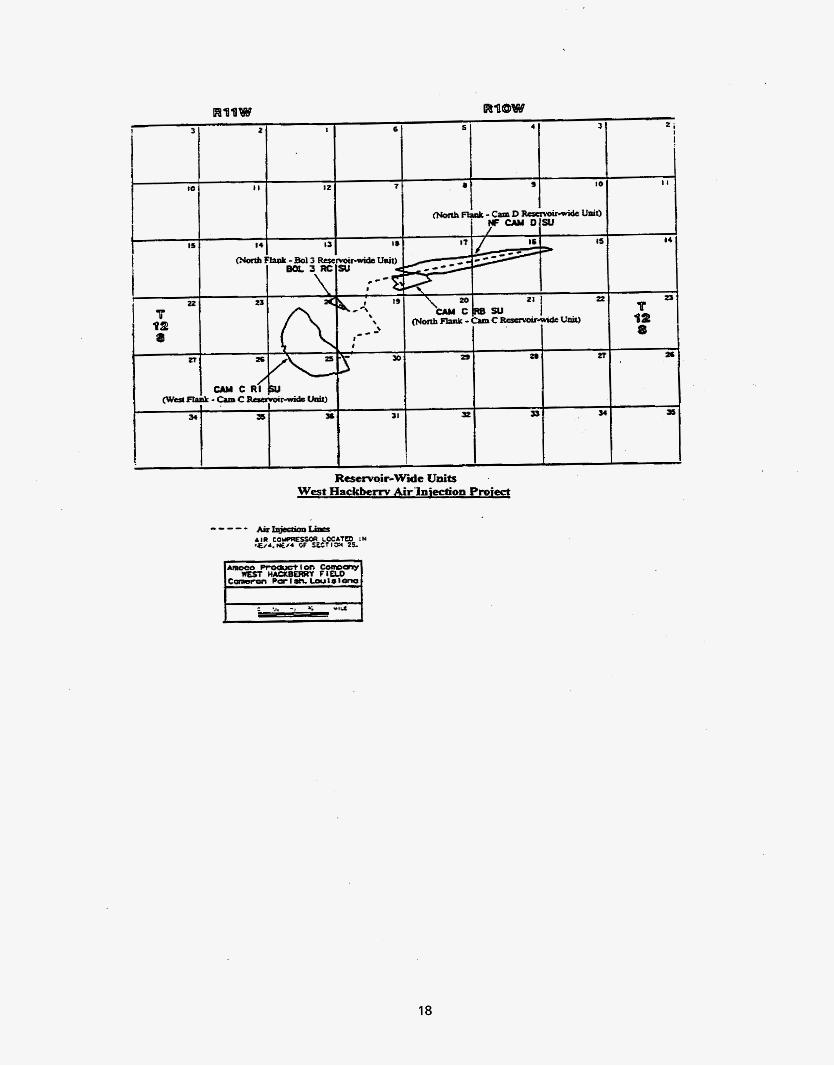
Reservoir-Wide Units West Hackbem Airlniedon Proiect
18

~~~~
TYPE LOG OLIGOCENE FIELD PAYS
- WEST HACKBERRY F 1 ELD
I Camer i no ( A I Sands:
c- I
C-2 c -3
D-2
8-2
Boi. 3 Sand
T I- I 00'
19

20

Cumulative Air Injected vs. l ime W. Hackberry Air lniection Proiect
3,000,000 1
+WatlG+lE)(W.Flank-FB 11) +GLD51i44(W.Flank-FB IV) --6-SL1558221(N,Flank Cam C: U G L A C 245(N.Flank-Bd3) Jlt CPSB 58(N.Flank-CamD) *Total Cumulative Air inj.
-%--
21

~~~ ~~
North Flank - Cam C Sand North South
Producer
Air Injector - ?sou
- 7WQ
Schematic Cross-Section
22

23

Composite Production Plot (North Flank Cam C (4 producers))
450 400 350 300 250 200 I50 100 50
0
24

t *s 9
I
North Flank - Bo1 3 Sand Amoco Product ton Cornpan:
W E S T HACKSERRY F I ELD C*omeron P a r t sh. L o u 1 s 1 a n c
I
STRUCTURE MAP BOL. 3 RC
-=
RQOW
I 8
25

Composite Production Plot (North Flank Bo1 3 (2 producers)) West Hackberrv Air lniection Proiect
140 -. +BOPD 4
+I
100
80
60
40
20
26

-. - ia
<
-. - I
--
I I
P Q2 8
I x
27
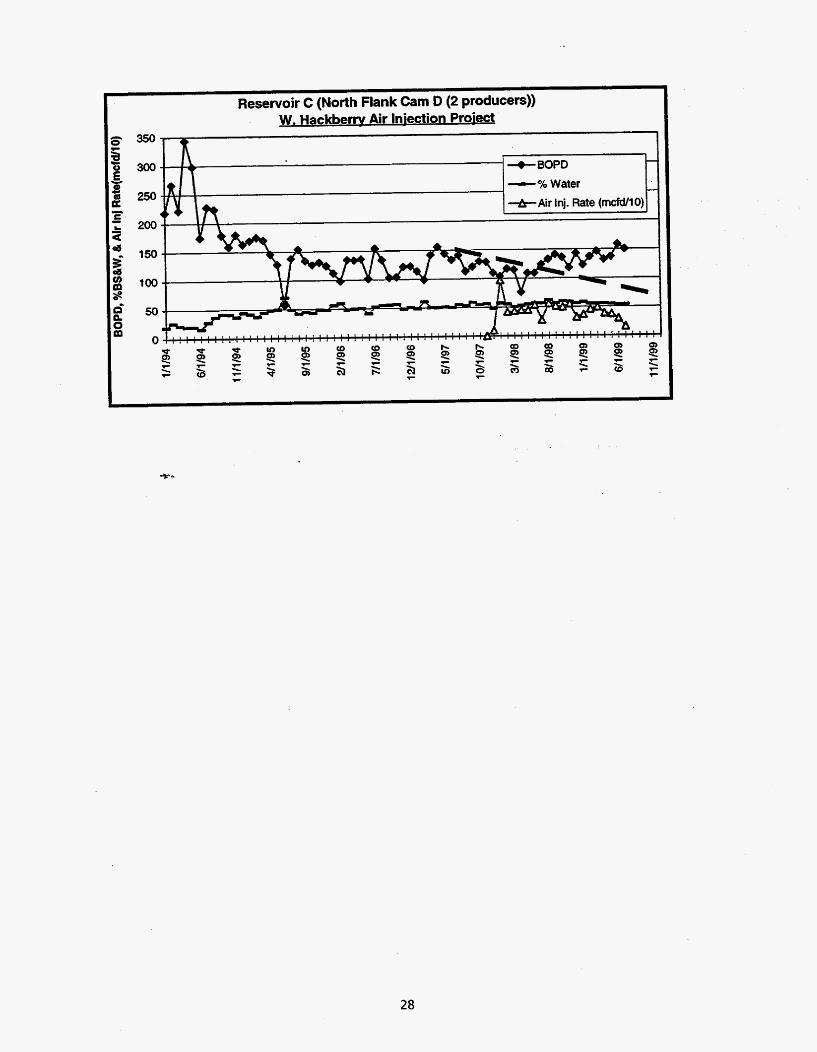
Reservoir C (North Flank Cam D (2 producers)) W. Hackbem Air lniection Proiect
350
300
250
200
150
100
50
0
-% Water
28

I
29

