well logging for earth scientists - home - springer978-1-4020-4602... · 2017-08-27 · by...
TRANSCRIPT

Well Logging for Earth Scientists

By
Ridgefield, CT, USA
Well Logging for Earth Scientists
2nd Edition
and
Darwin V. Ellis
Julian M. SingerRichmond, UK
Schlumberger-Doll Research,

Published by Springer,
www.springer.com
Printed on acid-free paper
ISBN 978-1-4020-4602-5 (e-book)
This is a second revised and enlarged edition of the first edition published by Elsevier NY, 1987.
A Manual of Solutions for the end-of-chapter problems can be found at the book’s homepage
of Schlumberger.
P.O. Box 17, 3300 AA Dordrecht, The Netherlands.
ISBN 978-1-4020-3738-2 (HB)
First published 2007
Reprinted with corrections 2008
Cover illustration: F irst recorded electric log, Pechelbronn field, Sept. 5, 1927, reproduced courtesy
in any form orNo part of this work may be reproduced, stored in a retrieval system, or transmitted
or otherwise,by any means, electronic, mechanical, photocopying, microfilming, recording
without wri tten permission from the Publisher, with the exception of any material supplied
for exclusive specifically for the purpose of being entered and executed on a computer system,
use by the purchaser of the work.
at www.springer.com
© 2007, 2008 Springer Science+Business Media B.V.
Library of Congress Control Number: 2008921855
Dedication
To a place where much of this was invented, elaborated, or pondered and where afriendship developed that even the writing of a book could not spoil.

Contents
Preface xvii
Acknowledgments xix
1 An Overview of Well Logging 11.1 Introduction 11.2 What is Logging? 2
1.2.1 What is Wireline Logging? 21.2.2 What is LWD? 5
1.3 Properties of Reservoir Rocks 71.4 Well Logging: The Narrow View 81.5 Measurement Techniques 101.6 How is Logging Viewed by Others? 11
References 15
2 Introduction to Well Log Interpretation:Finding the Hydrocarbon 172.1 Introduction 172.2 Rudimentary Interpretation Principles 172.3 The Borehole Environment 212.4 Reading a Log 252.5 Examples of Curve Behavior and Log Display 292.6 A Sample Rapid Interpretation 33
References 37Problems 38
3 Basic Resistivity and Spontaneous Potential 413.1 Introduction 413.2 The Concept of Bulk Resistivity 423.3 Electrical Properties of Rocks and Brines 463.4 Spontaneous Potential 493.5 Log Example of the SP 56
References 58Problems 59
vii
viii CONTENTS
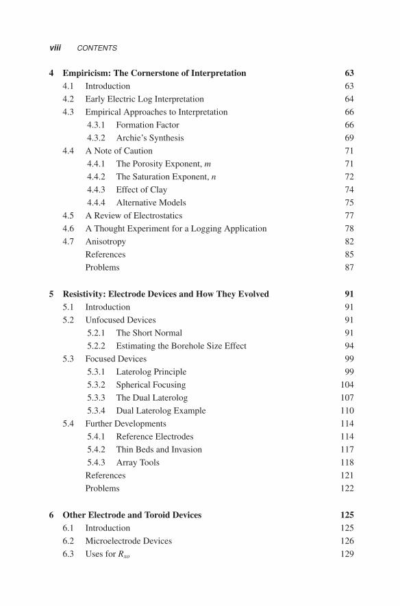
4 Empiricism: The Cornerstone of Interpretation 634.1 Introduction 634.2 Early Electric Log Interpretation 644.3 Empirical Approaches to Interpretation 66
4.3.1 Formation Factor 664.3.2 Archie’s Synthesis 69
4.4 A Note of Caution 714.4.1 The Porosity Exponent, m 714.4.2 The Saturation Exponent, n 724.4.3 Effect of Clay 744.4.4 Alternative Models 75
4.5 A Review of Electrostatics 774.6 A Thought Experiment for a Logging Application 784.7 Anisotropy 82
References 85Problems 87
5 Resistivity: Electrode Devices and How They Evolved 915.1 Introduction 915.2 Unfocused Devices 91
5.2.1 The Short Normal 915.2.2 Estimating the Borehole Size Effect 94
5.3 Focused Devices 995.3.1 Laterolog Principle 995.3.2 Spherical Focusing 1045.3.3 The Dual Laterolog 1075.3.4 Dual Laterolog Example 110
5.4 Further Developments 1145.4.1 Reference Electrodes 1145.4.2 Thin Beds and Invasion 1175.4.3 Array Tools 118References 121Problems 122
6 Other Electrode and Toroid Devices 1256.1 Introduction 1256.2 Microelectrode Devices 1266.3 Uses for Rxo 129
CONTENTS ix
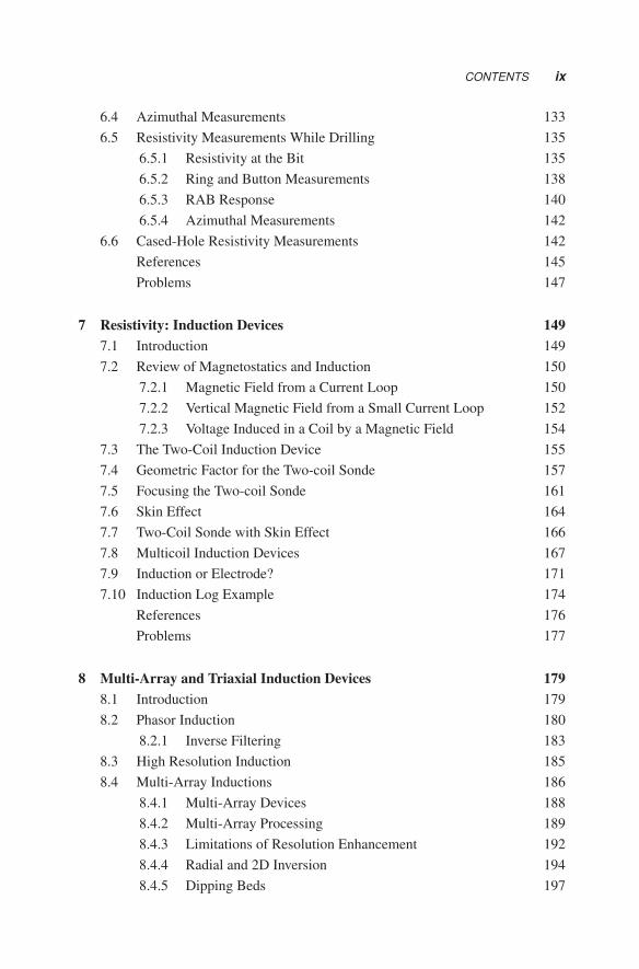
6.4 Azimuthal Measurements 1336.5 Resistivity Measurements While Drilling 135
6.5.1 Resistivity at the Bit 1356.5.2 Ring and Button Measurements 1386.5.3 RAB Response 1406.5.4 Azimuthal Measurements 142
6.6 Cased-Hole Resistivity Measurements 142References 145Problems 147
7 Resistivity: Induction Devices 1497.1 Introduction 1497.2 Review of Magnetostatics and Induction 150
7.2.1 Magnetic Field from a Current Loop 1507.2.2 Vertical Magnetic Field from a Small Current Loop 1527.2.3 Voltage Induced in a Coil by a Magnetic Field 154
7.3 The Two-Coil Induction Device 1557.4 Geometric Factor for the Two-coil Sonde 1577.5 Focusing the Two-coil Sonde 1617.6 Skin Effect 1647.7 Two-Coil Sonde with Skin Effect 1667.8 Multicoil Induction Devices 1677.9 Induction or Electrode? 1717.10 Induction Log Example 174
References 176Problems 177
8 Multi-Array and Triaxial Induction Devices 1798.1 Introduction 1798.2 Phasor Induction 180
8.2.1 Inverse Filtering 1838.3 High Resolution Induction 1858.4 Multi-Array Inductions 186
8.4.1 Multi-Array Devices 1888.4.2 Multi-Array Processing 1898.4.3 Limitations of Resolution Enhancement 1928.4.4 Radial and 2D Inversion 1948.4.5 Dipping Beds 197
x CONTENTS
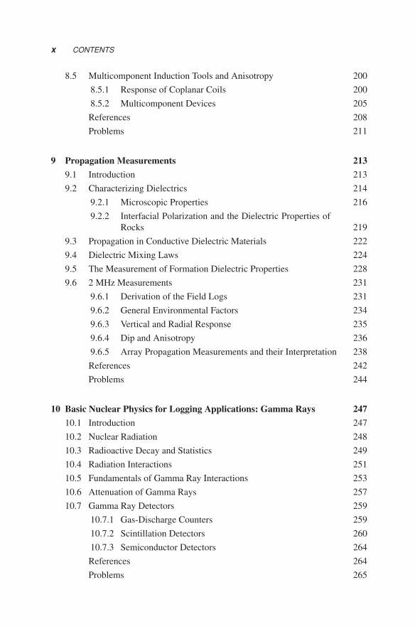
8.5 Multicomponent Induction Tools and Anisotropy 2008.5.1 Response of Coplanar Coils 2008.5.2 Multicomponent Devices 205References 208Problems 211
9 Propagation Measurements 2139.1 Introduction 2139.2 Characterizing Dielectrics 214
9.2.1 Microscopic Properties 2169.2.2 Interfacial Polarization and the Dielectric Properties of
Rocks 2199.3 Propagation in Conductive Dielectric Materials 2229.4 Dielectric Mixing Laws 2249.5 The Measurement of Formation Dielectric Properties 2289.6 2 MHz Measurements 231
9.6.1 Derivation of the Field Logs 2319.6.2 General Environmental Factors 2349.6.3 Vertical and Radial Response 2359.6.4 Dip and Anisotropy 2369.6.5 Array Propagation Measurements and their Interpretation 238References 242Problems 244
10 Basic Nuclear Physics for Logging Applications: Gamma Rays 24710.1 Introduction 24710.2 Nuclear Radiation 24810.3 Radioactive Decay and Statistics 24910.4 Radiation Interactions 25110.5 Fundamentals of Gamma Ray Interactions 25310.6 Attenuation of Gamma Rays 25710.7 Gamma Ray Detectors 259
10.7.1 Gas-Discharge Counters 25910.7.2 Scintillation Detectors 26010.7.3 Semiconductor Detectors 264References 264Problems 265

CONTENTS xi
11 Gamma Ray Devices 26711.1 Introduction 26711.2 Sources of Natural Radioactivity 26811.3 Gamma Ray Devices 27111.4 Uses of the Gamma Ray Measurement 27311.5 Spectral Gamma Ray Logging 275
11.5.1 Spectral Stripping 28011.6 Developments in Spectral Gamma Ray Logging 28311.7 A Note on Depth of Investigation 285
References 286Problems 288
12 Gamma Ray Scattering and Absorption Measurements 28912.1 Introduction 28912.2 Density and Gamma Ray Attenuation 290
12.2.1 Density Measurement Technique 29312.2.2 Density Compensation 296
12.3 Lithology Logging 30012.3.1 Photoelectric Absorption and Lithology 30012.3.2 Pe Measurement Technique 30412.3.3 Interpretation of Pe 307
12.4 Inversion of Forward Models with Multidetector Tools 31212.5 LWD Density Devices 31212.6 Environmental Effects 31412.7 Estimating Porosity from Density Measurements 317
12.7.1 Interpretation Parameters 318References 321Problems 322
13 Basic Neutron Physics for Logging Applications 32513.1 Introduction 32513.2 Fundamental Neutron Interactions 32613.3 Nuclear Reactions and Neutron Sources 33213.4 Useful Bulk Parameters 333
13.4.1 Macroscopic Cross Sections 33313.4.2 Lethargy and Average Energy Loss 33513.4.3 Number of Collisions to Slow Down 33613.4.4 Characteristic Lengths 33713.4.5 Characteristic Times 344
xii CONTENTS
13.5 Neutron Detectors 345References 347Problems 348
14 Neutron Porosity Devices 35114.1 Introduction 35114.2 Use of Neutron Porosity Devices 35314.3 Types of Neutron Tools 35314.4 Basis of Measurement 35414.5 Historical Measurement Technique 35814.6 A Generic Thermal Neutron Tool 36114.7 Typical Log Presentation 36414.8 Environmental Effects 366
14.8.1 Introduction to Correction Charts 36714.9 Major Perturbations of Neutron Porosity 370
14.9.1 Lithology Effect 37014.9.2 Shale Effect 37214.9.3 Gas Effect 373
14.10 Depth of Investigation 37414.11 LWD Neutron Porosity Devices 37814.12 Summary 379
References 379Problems 381
15 Pulsed Neutron Devices and Spectroscopy 38315.1 Introduction 38315.2 Thermal Neutron Die-Away Logging 384
15.2.1 Thermal Neutron Capture 38415.2.2 Measurement Technique 38615.2.3 Instrumentation 39015.2.4 Interpretation 392
15.3 Pulsed Neutron Spectroscopy 39515.3.1 Evolution of Measurement Technique 400
15.4 Pulsed Neutron Porosity 40515.5 Spectroscopy 408
References 410Problems 413
CONTENTS xiii
16 Nuclear Magnetic Logging 41516.1 Introduction 415
16.1.1 Nuclear Resonance Magnetometers 416
16.1.2 Why Nuclear Magnetic Logging? 417
16.2 A Look at Magnetic Gyroscopes 418
16.2.1 The Precession of Atomic Magnets 419
16.2.2 Paramagnetism of Bulk Materials 421
16.3 Some Details of Nuclear Induction 423
16.3.1 Longitudinal Relaxation, T1 424
16.3.2 Rotating Frame 427
16.3.3 Pulsing 429
16.3.4 Transverse Relaxation, T2, and Spin Dephasing 430
16.3.5 Spin Echoes 431
16.3.6 Relaxation and Diffusion in Magnetic Gradients 432
16.3.7 Measurement Sensitivity 434
16.4 NMR Properties of Bulk Fluids 436
16.4.1 Hydrogen Index 436
16.4.2 Bulk Relaxation in Water and Hydrocarbons 437
16.4.3 Viscosity Correlations for Crude Oils 440
16.5 NMR Relaxation in Porous Media 442
16.5.1 Surface Interactions 443
16.5.2 Pore Size Distribution 446
16.5.3 Diffusion Restriction 448
16.5.4 Internal Magnetic Gradients 449
16.6 Operation of a First Generation Nuclear Magnetic Logging Tool 449
16.7 The NMR Renaissance of “Inside-Out” Devices 452
16.7.1 A New Approach 452
16.7.2 Numar/Halliburton MRIL 454
16.7.3 Schlumberger CMR and Subsequent Developments 455
16.7.4 LWD Devices 458
16.8 Applications and Log Examples 459
16.8.1 Tool Planners 459
16.8.2 Porosity and Free-Fluid Porosity 460
16.8.3 Pore Size Distribution and Permeability Estimation 463
16.8.4 Fluid Typing 465
16.9 Summary 471

xiv CONTENTS
16.10 Appendix A: Diffusion 472References 473Problems 477
17 Introduction to Acoustic Logging 47917.1 Introduction to Acoustic Logging 47917.2 Short History of Acoustic Measurements
in Boreholes 48017.3 Applications of Borehole Acoustic Logging 48217.4 Review of Elastic Properties 48317.5 Wave Propagation 48917.6 Rudimentary Acoustic Logging 49317.7 Rudimentary Acoustic Interpretation 494
References 496Problems 497
18 Acoustic Waves in Porous Rocks and Boreholes 49918.1 Introduction 49918.2 A Review of Laboratory Measurements 50018.3 Porolelastic Models of Rocks 50918.4 The Promise of Vp/Vs 513
18.4.1 Lithology 51318.4.2 Gas Detection and Quantification 51518.4.3 Mechanical Properties 51718.4.4 Seismic Applications (AVO) 518
18.5 Acoustic Waves in Boreholes 51918.5.1 Borehole Flexural Waves 52418.5.2 Stoneley Waves 525References 527Problems 529
19 Acoustic Logging Methods 53119.1 Introduction 53119.2 Transducers – Transmitters and Receivers 53219.3 Traditional Sonic Logging 534
19.3.1 Some Typical Problems 54019.3.2 Long Spacing Sonic 541
19.4 Evolution of Acoustic Devices 54419.4.1 Arrays of Detectors 546
CONTENTS xv
19.4.2 Dipole Tools 54719.4.3 Shear Wave Anisotropy and Crossed Dipole Tools 54919.4.4 LWD 55319.4.5 Modeling-driven Tool Design 553
19.5 Acoustic Logging Applications 55419.5.1 Formation Fluid Pressure 55519.5.2 Mechanical Properties and Fractures 55719.5.3 Permeability 55919.5.4 Cement Bond Log 561
19.6 Ultrasonic Devices 56219.6.1 Pulse-Echo Imaging 56319.6.2 Cement Evaluation 565References 566Problems 568
20 High Angle and Horizontal Wells 57320.1 Introduction 57320.2 Why are HA/HZ Wells Different? 57420.3 Measurement Response 576
20.3.1 Resistivity 57720.3.2 Density 58020.3.3 Neutron 58220.3.4 Other Measurements 584
20.4 Geosteering 58520.4.1 Deep Reading Devices for Geosteering 589References 593Problems 594
21 Clay Quantification 59721.1 Introduction 59721.2 What is Clay/Shale? 598
21.2.1 Physical Properties of Clays 59921.2.2 Total Porosity and Effective Porosity 60121.2.3 Shale Distribution 60421.2.4 Influence on Logging Measurements 606
21.3 Shale Determination from Single Measurements 60921.3.1 Interpretation of Pe in Shaly Sands 61021.3.2 Neutron Response to Shale 613
xvi CONTENTS
21.3.3 Response of � to Clay Minerals 61621.4 Neutron–Density Plots 61721.5 Elemental Analysis 62121.6 Clay Typing 624
References 624Problems 626
22 Lithology and Porosity Estimation 62922.1 Introduction 62922.2 Graphical Approach for Binary Mixtures 63022.3 Combining Three Porosity Logs 636
22.3.1 Lithology Logging: Incorporating Pe 64022.3.2 Other Methods 643
22.4 Numerical Approaches to Lithology Determination 64422.4.1 Quantitative Evaluation 647
22.5 General Evaluation Methods 648References 650Problems 651
23 Saturation and Permeability Estimation 65323.1 Introduction 65323.2 Clean Formations 65423.3 Shaly Formations 658
23.3.1 Early Models 66123.3.2 Double Layer Models 66223.3.3 Saturation Equations 66523.3.4 Laminated Sands 668
23.4 Carbonates and Heterogeneous Rocks 67123.5 Permeability from Logs 674
23.5.1 Resistivity and Porosity 67523.5.2 Petrophysical Models 676References 681Problems 684
Index 687

Preface
Twenty years ago, the objectives of the first edition of this book were numerous andambitious: to demystify the process of well log analysis; to examine the physical basisof the multitude of geophysical measurements known collectively as well logging; toclearly lay out the assumptions and approximations routinely used to extract petro-physical information from these geophysical measurements; to expose the vast rangeof well logging instrumentation and techniques to the larger geophysical community.Finally, there was the important goal of providing a textbook for university and gradu-ate students in Geophysics and Petroleum Engineering, where none suitable had beenavailable before.
What’s different twenty years later? First of all, Well Logging for Earth Scientistsis long out of print. The petroleum industry, the major consumer of the geophysicalinformation known as well logging, has changed enormously: technical staffs havebeen slashed, and hydrocarbons have become increasingly harder to locate, quantify,and produce. In addition, new techniques of drilling high deviation or horizontalwells have engendered a whole new family of measurement devices incorporatedinto the drilling string that may be used routinely or in situations where access bytraditional “wireline” instruments is difficult or impossible. Petroleum deposits arebecoming scarce and demand is steadily increasing. Massive corporate restructuringand the “graying” of the workforce have caused the technical competence involvedin the search and exploitation of petroleum to become scarce. Although we are onlyattempting to address this latter scarcity with our textbook, the objectives are stillambitious.
In this thorough updating of the text, we have attempted to include all of the newlogging measurement technology developed in the last twenty years and to expandthe petrophysical applications of the measurements. As in the first edition, we areprimarily concerned with logging techniques that lead to formation evaluation, butmention a few other applications where appropriate. We also trace the historicaldevelopment of the technology as a means of better understanding it. Throughout,large sections of the text have been set in italics, which may be skipped by the casualreader. These detailed sections may be of more interest to researchers. The goals ofproviding a graduate level textbook as well as a useful handbook for any practicingearth scientist (geophysicist, geologist, petroleum engineer, petrophysicist) remain.
Darwin EllisJulian Singer
xvii
Acknowledgments
The authors would like to acknowledge the special help received from a number ofindividuals, without which this tome could not have been achieved.
Therefore we owe our thanks to:Chuck Fulton, Charlie Flaum, Richard Woodhouse, and Austin Boyd for log ex-
amples;Tom Plona, Lalitha Venkataramanan, Drew Pomerantz, Tancredi Botto, Alan Sib-
bit, Jacques Tabanou, Jack LaVigne, Barbara Anderson, Nikita Seleznev, and NickBennett for critically reviewing early versions of various chapters;
John Hsu, David Johnson, Tarek Habashy, Chris Straley, and Pabitra Sen for helpfuldiscussions;
Charlie Case, Joe Chiaramonte, Laurent Mosse and especially to Mehdi Hizemfor substantial contributions to the form and content of several chapters;
George Stewart for the drafting of the figures;and Frank Shray, Tarek Habashy, Mark Andersen, Martin Issacs and Vicki King
for help in innumerable ways with the multitude of figures.For the deficiencies, errors, and omissions, both in the text and in these acknowl-
edgements, the blame rests with us.
Darwin Ellis & Julian Singer
The authors also are grateful for the use of a number of figures, in this new edition,drawn from Schlumberger’s Oilfield Review. The following figures are copyrightSchlumberger Ltd. Used with permission.
Fig. 6.6 Fig. 16.24Fig. 12.20 Fig. 16.27Fig. 12.21 Fig. 16.32Fig. 15.9 Fig. 16.34Fig. 15.10 Fig. 16.36Fig. 15.12 Fig. 16.37Fig. 15.13 Fig 18.15Fig. 15.14 Fig. 18.16Fig. 15.15 Fig. 18.24Fig. 15.17 Fig.19.19Fig 15.18 Fig. 19.20Fig. 15.19 Fig. 19.21Fig. 16.9 Fig. 19.26Fig. 16.22 Fig. 19.27
4 Dec. 2006
xix