welding & pipe inspection training manual
DESCRIPTION
Useful for the welding inspector, trainees in the filed of inspection. Manual included measurement system commonly used.TRANSCRIPT

TRAINNING ON VISUAL
INSPECTION

ContentsContents
1. General guideline for visual Inspection
2. Visual Defects in Steel
3. Visual Defects in Welding

General guideline for
Visual Inspection

Definition of Visual Inspection
Visual inspection is the monitoring of specific parameters by visual and optical assessments of test objects and surfaces.
Inspection may be by the use of the eye alone or can be enhanced using optical systems such as magnifiers and microscopes. A variety of equipment is available to the visual inspector including mirrors and gauges.

Conditions for visual inspection
Visual inspection must take place in a clean, comfortable environment with adequate lighting. There should be reasonable access to the parts to be inspected and attention should be paid to safety, working position, and atmospheric conditions. The test piece should be clean and free from protective coatings. Any equipment to be used should be checked for accuracy and its operation understood by the inspector.

1.Sufficient Illumination2.Correct eye distance from object
and correct angle between eye & object
3.Mirror, magnifying glasses to use if required
General guideline for Visual Inspection

1. Sufficient Illumination :
No vision without illumination At least 300 lux as per API 5L, 44th
edition At least 1000 lux as per ASME Sec V
General guideline for Visual Inspection

Near Vision Examination
The applicant is capable of reading a minimum of Jaeger No.2 or equivalent type and size of letter at a distance of not less than 12 inches on a standard Jaeger test chart. The ability to perceive an Ortho-Rater minimum of 8 or a similar test pattern is also acceptable. This test should he administered annually. Candidates must also he capable of differentiating different shades of colors - this color vision must be tested every 3 years.
This is specified in ASNT document number SNT-TC-1A.

Viewing angles and distances
It is recommended that direct vision testing should be carried out between 250 mm and 600mm and the angle between the eye and test surface not less than 30°.

Rules Thin steel rules are used by the visual
inspector for accuracy, i.e. less parallax error, good dimensional stability and small width of graticules. Measurement markings may he metric, imperial or both. The smallest increment is usually 0.5 mm or 1/64 inch.

Visual Defects in
Steels

Arc Burns Blister Cracks Dents Hard Spot Inclusion Lamination Tong mark
Visual Defects in Steels
Lap Pitting Roll Mark Rolled-in-Scale Scab Seam Sliver Seam line
+ + + And So many

Visual Defects in Steels
Arc Burn
Localized point of the surface melting caused by the arcing between electrode/ground and pipe surface

Arc burnArc burn

Visual Defects in Steels
Blistering
A raised spot on the plate surface caused by the pocketing of the gas within the plate wall

BlisteringBlistering

Visual Defects in Steels
Cracks
Internal ruptures in steel caused by stresses which arise
from the combination of several factors, such as volume
changes due to transformation, brittleness due to the
presence of hydrogen, and the arrangement of the micro-
structure, resulting from hot working.

Cracks

Visual Defects in Steels
Dents
A local change in the surface contour caused by mechanical impact, but not accompanied by the material loss.

DentDent

Visual Defects in Steels
Hard Spot
Area of the pipe having hardness level considerably high as compare with surrounding metal usually due to localized quenching.

Visual Defects in Steels
Gauge mark
Elongated grooves or cavities caused by removal of metal
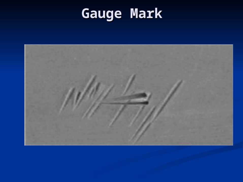
Gauge MarkGauge Mark
Chisel MarksChisel Marks

Visual Defects in Steels
Inclusion
Foreign material or non metallic particle entrapped within the metal during solidification

InclusionsInclusions

InclusionInclusion

Visual Defects in Steels
LaminationInternal metal separation creating layers
generally parallel to surface
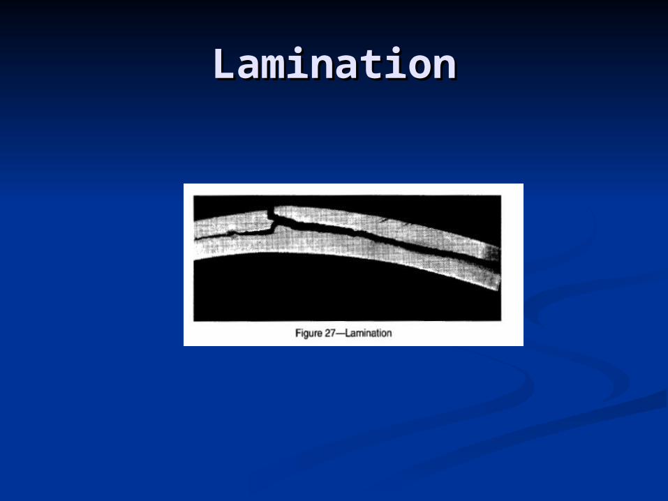
LaminationLamination

Visual Defects in Steels
LapFold of metal which has been rolled or otherwise
worked against the surface of the rolled metal , but has not fused into sound metal

LapLap

Visual Defects in Steels
PittingDepression resulting from the removal of foreign
material rolled into the surface during the manufacture.
And
Depression resulting from impression of foreign material into the plate surface during the manufacturing.

Pitting

Visual Defects in Steels
Roll MarkA term applied to the surface imperfection
caused by improper rolled alignment or roll surface damage.

Roll Mark

Visual Defects in Steels
Roll in-slugA term applied to the surface imperfection
caused by improper rolled alignment or roll surface damage.

Roll In-Slugs

Visual Defects in Steels
SliverA extremely thin elongated piece of metal that has been
rolled into the surface of the parent metal to which it is attached usually by the one end.
Sliver is caused by the poor rolling mill practices, billet defects, improper biller conditioning, high rolling speed etc

Sliver

Visual Defects in Steels
ScabImperfection in the form of a shell, generally attached to
the surface by sound metal.
Scabs are irregularly shaped, flattened protrusions caused by splash, boiling or other problems from teeming, casting, or conditioning

Scab
Visual Defects in Steels
Seam
Crevice in the rolled metal which has been more or less closed by rolling or other work but has not been fused into sound metal.

Visual Defects in
Pipes Body(Due to Process and poor workmanship)

Improper GrindingImproper Grinding
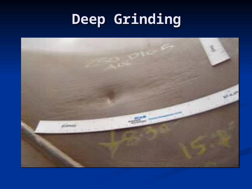
Deep GrindingDeep Grinding

Chips MarkChips Mark

Visual Defects in
Welding

Adobe Acrobat Document
Thank youThank you