welding of uddeholm tool steels · uddeholm welding consumable are designed to be compatible with...
TRANSCRIPT

TREATMENT WELDING OF TOOL STEEL 1
WELDING OF UDDEHOLMTOOL STEELS

2 TREATMENT WELDING OF TOOL STEEL
This information is based on our present state of knowledge and is intended to provide general notes on our products and their uses. It should not therefore be construed as a warranty of specific properties of the products described or a warranty for fitness for a particular purpose.
Classified according to EU Directive 1999/45/ECFor further information see our “Material Safety Data Sheets”.
Edition 7, 10.2017
© UDDEHOLMS ABNo part of this publication may be reproduced or transmitted for commercial purposes without permission of the copyright holder.
TREATMENT WELDING OF TOOL STEEL 3
CONTENTS
General information on welding of tool steel ..................... 4
Welding methods for tool steel .......................................... 4
The welding bay ................................................................ 6
Filler material ..................................................................... 7
Hydrogen in tool steel ....................................................... 8
Elevated working temperature .......................................... 9
Welding procedure ............................................................ 10
Heat treatment after welding ............................................. 11
Guidelines for welding in
– hot work tool steel ........................................................ 13– cold work tool steel ..................................................... 14– plastic mould steel ........................................................ 17
4 TREATMENT WELDING OF TOOL STEEL
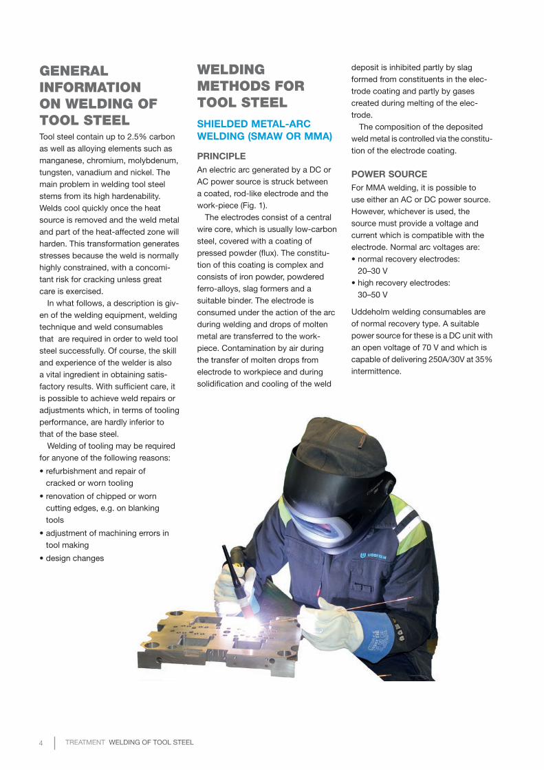
WELDING METHODS FOR TOOL STEELSHIELDED METAL-ARC WELDING (SMAW OR MMA)
PRINCIPLEAn electric arc generated by a DC or AC power source is struck between a coated, rod-like electrode and the work-piece (Fig. 1).
The electrodes consist of a central wire core, which is usually low-carbon steel, covered with a coating of pressed powder (flux). The constitu-tion of this coating is complex and consists of iron powder, powdered ferro-alloys, slag formers and a suitable binder. The electrode is consumed under the action of the arc during welding and drops of molten metal are transferred to the work-piece. Contamination by air during the transfer of molten drops from electrode to workpiece and during solidification and cooling of the weld
GENERAL INFORMATION ON WELDING OF TOOL STEELTool steel contain up to 2.5% carbon as well as alloying elements such as manganese, chromium, molybdenum, tungsten, vanadium and nickel. The main problem in welding tool steel stems from its high hardenability. Welds cool quickly once the heat source is removed and the weld metal and part of the heat-affected zone will harden. This transformation generates stresses because the weld is normally highly constrained, with a concomi-tant risk for cracking unless great care is exercised.
In what follows, a description is giv-en of the welding equipment, welding technique and weld consumables that are required in order to weld tool steel successfully. Of course, the skill and experience of the welder is also a vital ingredient in obtaining satis-factory results. With sufficient care, it is possible to achieve weld repairs or adjustments which, in terms of tooling performance, are hardly inferior to that of the base steel.
Welding of tooling may be required for anyone of the following reasons:
• refurbishment and repair ofcracked or worn tooling
• renovation of chipped or worncutting edges, e.g. on blankingtools
• adjustment of machining errors intool making
• design changes
deposit is inhibited partly by slag formed from constituents in the elec-trode coating and partly by gases created during melting of the elec-trode.
The composition of the deposited weld metal is controlled via the constitu-tion of the electrode coating.
POWER SOURCEFor MMA welding, it is possible to use either an AC or DC power source. However, whichever is used, the source must provide a voltage and current which is compatible with the electrode. Normal arc voltages are:• normal recovery electrodes:
20–30 V• high recovery electrodes:
30–50 V
Uddeholm welding consumables are of normal recovery type. A suitable power source for these is a DC unit with an open voltage of 70 V and which is capable of delivering 250A/30V at 35% intermittence.
TREATMENT WELDING OF TOOL STEEL 5
GAS TUNGSTEN-ARC WELDING (GTAW OR TIG)
PRINCIPLEIn MMA welding, the electrode from which the arc is struck is consumed during welding.
The electrode in TIG welding is made of tungsten or tungsten alloy which has a very high melting point (about 3300°C/6000°F) and is there-fore not consumed during the process (Fig. 2). The arc is initially struck by subjecting the electrode-workpiece gas to a high-frequency voltage. The resulting ionization permits striking without the necessity for contact between electrode and workpiece. The tungsten electrode is always con-nected to the negative terminal of a DC power source because this minimizes heat generation and thereby any risk of melting the electrode.
Current is conducted to the electrode via a contact inside the TIG-gun. Any consumables which are required during TIG-welding are fed obliquely into the arc in the form of rod or wire. Oxidation of the weld pool is pre-vented by an inert-gas shroud which streams from the TIG gun over the electrode and weld.
POWER SOURCETIG welding can be performed with a regular MMA power source provided this is complemented with a TIG control unit. A water cooled gun is normally not necessary as the actual welding time is very limited. A gas lens is also a desirable feature in order that the inert gas protection is as efficient as possible. Welding is facilitated if the current can be increased steplessly from zero to the optimum level.
LASER WELDING
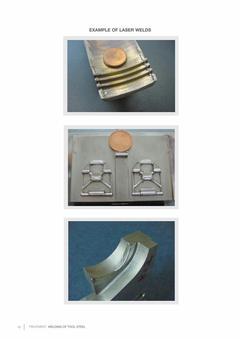
PRINCIPLEHigh power laser light is generated and focused through a lens to the welding spot. As filler material a thin wire with a diameter between 0.1– 0.6 mm is primarily used. The welder guides the wire to the area to be welded. The laser beam melt the wire and the base material. The molten material solidifies leaving behind a small raised area. The welder continues spot by spot and line by line. An Argon gas at higher purity than used at TIG-welding should be used to shields the process from oxidation (Fig. 3).
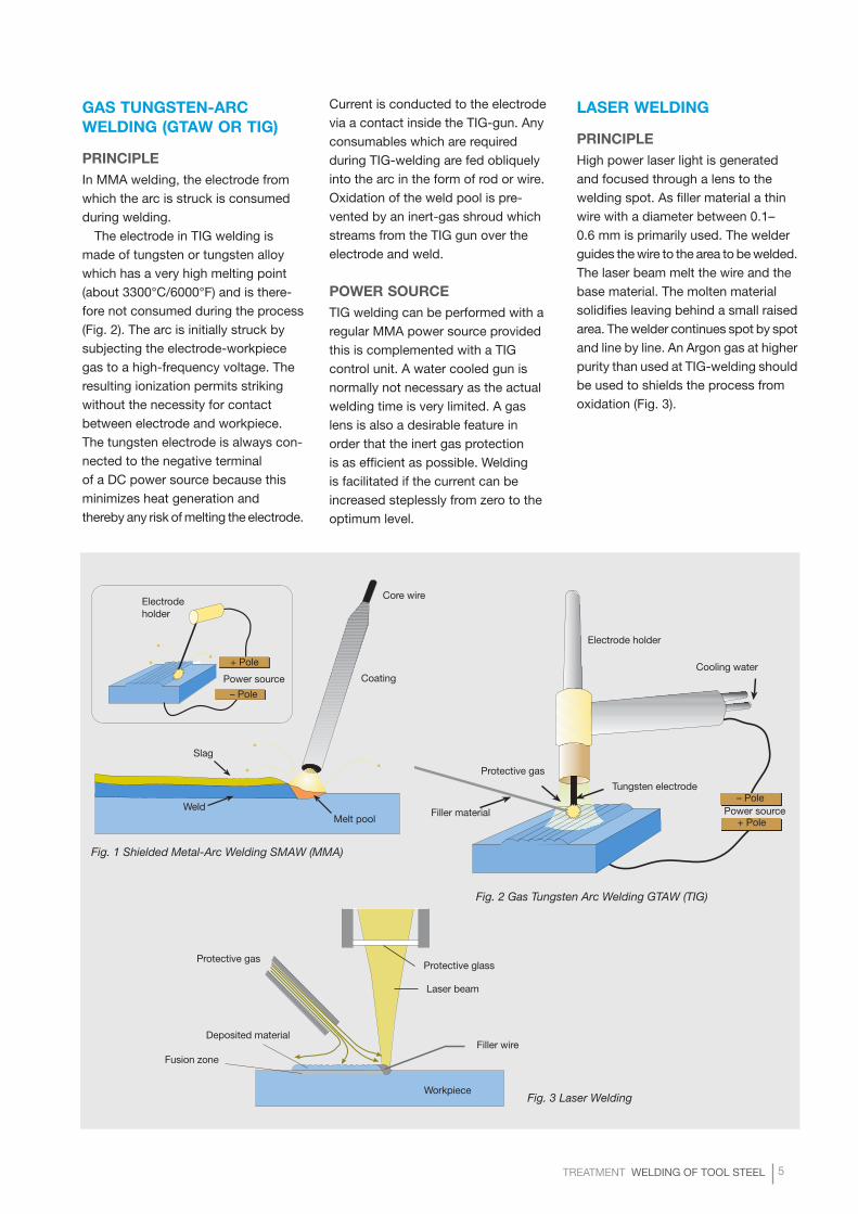
Fig. 1 Shielded Metal-Arc Welding SMAW (MMA)
Fig. 2 Gas Tungsten Arc Welding GTAW (TIG)
Fig. 3 Laser Welding
Slag
WeldMelt pool
Coating
Core wireElectrode holder
+ Pole
– Pole
Power source
Protective gas
Filler material
Tungsten electrode
Cooling water
Electrode holder
– Pole
+ PolePower source
Protective gasProtective glass
Laser beam
Filler wire
Workpiece
Deposited material
Fusion zone
6 TREATMENT WELDING OF TOOL STEEL
GRINDING MACHINESThe following should be available:• disc grinder with a suitable wheel for preparing the joint and grinding out of any defects which may occur during welding. Wheel dimension depends on defect size, which has to be grinded.
• flat grinder capable of ≥25 000 rpm for grinding of minor defects and of the finished weld
• if a welded mould is subsequently to be polished or photo-etched, it may be necessary to have a grinder capable of giving a sufficiently fine finish
• small rotating metal files in different shapes and sizes
THE WELDING BAYIn order to be able to effect satis-factory welding work on tool steel, the following items of equipment are to be regarded as minimum require-ments.
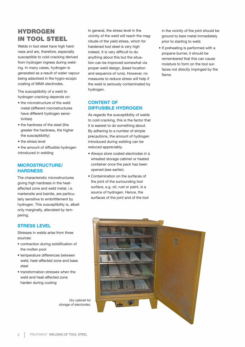
DRY CABINETThe coated electrodes used for MMA welding are strongly hygroscopic and should not be allowed to come into contact with anything other than dry air. Otherwise, the weld will be contaminated with hydrogen (see later). Hence, the welding bay should
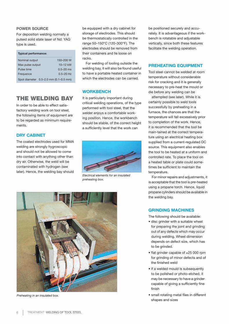
Preheating in an insulated box.
Electrical elements for an insulated preheating box.
WORKBENCHIt is particularly important during critical welding operations, of the type performed with tool steel, that the welder enjoys a comfortable work-ing position. Hence, the workbench should be stable, of the correct height a sufficiently level that the work can
PREHEATING EQUIPMENTTool steel cannot be welded at room temperature without considerable risk for cracking and it is generally necessary to pre-heat the mould or die before any welding can be
attempted (see later). While it is certainly possible to weld tools successfully by preheating in a furnace, the chances are that the temperature will fall excess ively prior to completion of the work. Hence, it is recommended that the tool be main-tained at the correct tempera-ture using an electrical heating box supplied from a current-regulated DC source. This equipment also enables the tool to be heated at a uniform and controlled rate. To place the tool on a heated table or plate could some-times be sufficient to maintain the temperature.
For minor repairs and adjustments, it is acceptable that the tool is pre-heated using a propane torch. Hence, liquid propane cylinders should be available in the welding bay.
be equipped with a dry cabinet for storage of electrodes. This should be thermostatically controlled in the range 50–150°C (120–300°F). The electrodes should be removed from their containers and lie loose on racks.
For welding of tooling outside the welding bay, it will also be found useful to have a portable heated container in which the electrodes can be carried.
be positioned securely and accu-rately. It is advantageous if the work-bench is rotatable and adjustable vertically, since both these features facilitate the welding operation.
POWER SOURCEFor deposition welding normally a pulsed solid state laser of Nd: YAG type is used.
Typical performance:
Nominal output 150–200 W
Max pulse output 10–12 kW
Pulse time 0.5–20 ms
Frequence 0.5–20 Hz
Spot diameter 0.5–2.0 mm (0.1–0.5 mm)
TREATMENT WELDING OF TOOL STEEL 7
FILLER MATERIALThe chemical composition of a weld deposit is determined by the compo-sition of the consumable (filler metal), the base steel composition and the extent to which the base material is melted during welding. The consum-able electrode or wire should mix easily with the molten base steel giving a deposit with:
• uniform composition, hardness andresponse to heat-treatment
• freedom from non-metallicinclusions, porosity or cracks
• suitable properties for the toolingapplication in question
Since tool steel welds have high hardness, they are particularly susceptible to cracking which may originate at slag particles or pores. Hence, the consumable used should be capable of producing a high-quality weld. In a similar vein, it is necessary that the consumables are produced with very tight analysis control in order that the hardness as welded and the response to heat treatment is reproducible from batch to batch. High-quality filler metals are also essential if a mould is to be polished or photo-etched after weld-ing. Uddeholm welding consumables meet these requirements.
Filler rods are normally produced from electroslag remelted stock. The coated electrodes are of basic type, which are far superior to rutile elec-trodes as regards weld cleanliness. Another advantage with basic coated electrodes over those of rutile type is that the former give a much lower hydrogen content in the weld metal.
In general, the consumable used for welding tool steel should be similar in composition to the base material. When welding in the an-nealed condition, e.g. if a mould or die has to be adjusted while in the process of manufacture, it is vital that the filler metal has the same heat treatment characteristics as the base steel, otherwise the welded area in the finished tool will have different hardness. Large compositional differences are also associated with an increased cracking risk in connec-tion with hardening.
Uddeholm welding consumable are designed to be compatible with the corresponding tool steel grades irrespective of whether welding is carried out on annealed or hardened and tempered base material.
Obviously, the weld metal of welded tools will require different properties for different applications.
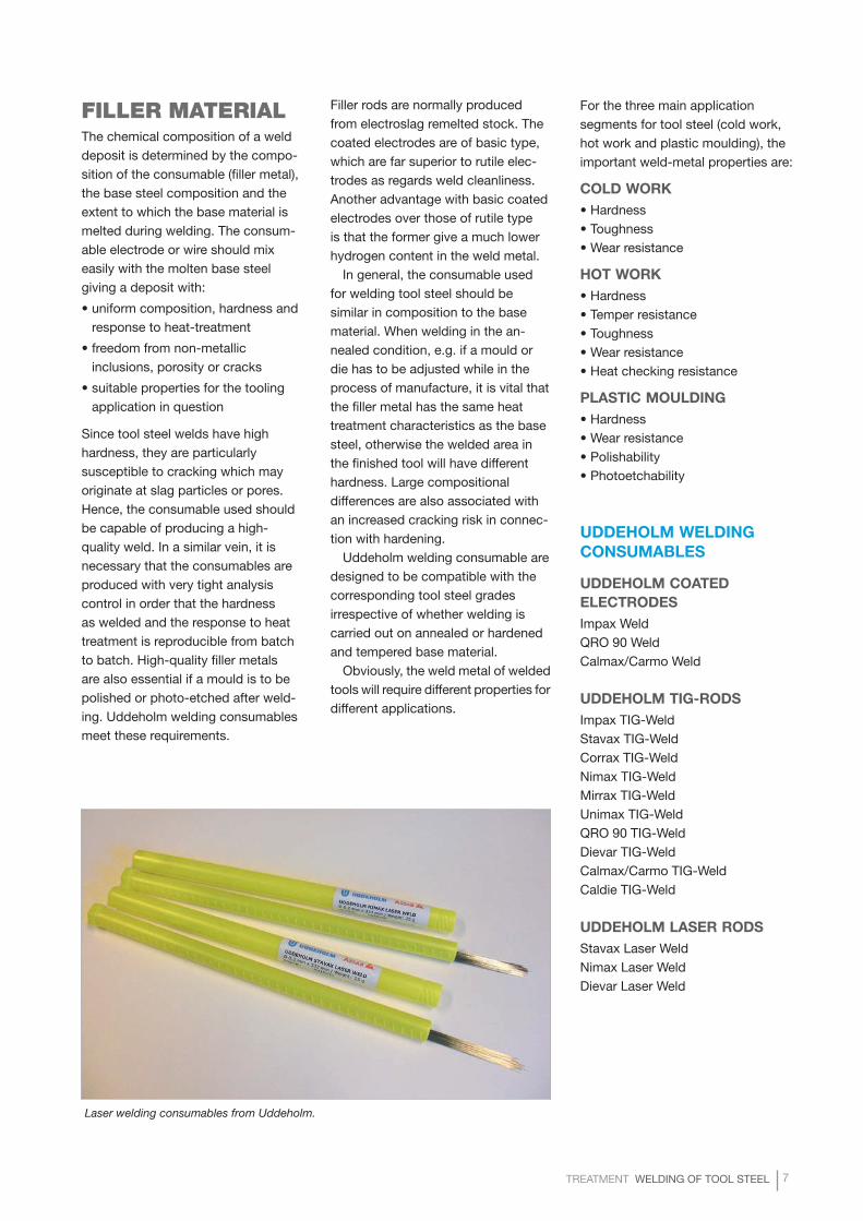
Laser welding consumables from Uddeholm.
For the three main application segments for tool steel (cold work, hot work and plastic moulding), the important weld-metal properties are:
COLD WORK• Hardness• Toughness• Wear resistance
HOT WORK• Hardness• Temper resistance• Toughness• Wear resistance• Heat checking resistance
PLASTIC MOULDING• Hardness• Wear resistance• Polishability• Photoetchability
UDDEHOLM WELDING CONSUMABLES
UDDEHOLM COATED ELECTRODESImpax WeldQRO 90 WeldCalmax/Carmo Weld
UDDEHOLM TIG-RODSImpax TIG-WeldStavax TIG-WeldCorrax TIG-WeldNimax TIG-WeldMirrax TIG-WeldUnimax TIG-WeldQRO 90 TIG-WeldDievar TIG-WeldCalmax/Carmo TIG-WeldCaldie TIG-Weld
UDDEHOLM LASER RODSStavax Laser WeldNimax Laser WeldDievar Laser Weld
8 TREATMENT WELDING OF TOOL STEEL
MICROSTRUCTURE/HARDNESSThe characteristic microstructures giving high hardness in the heat-affected zone and weld metal, i.e. martensite and bainite, are particu-larly sensitive to embrittlement by hydrogen. This susceptibility is, albeit only marginally, alleviated by tem-pering.
STRESS LEVELStresses in welds arise from three sources:
• contraction during solidification ofthe molten pool
• temperature differences betweenweld, heat-affected zone and basesteel
• transformation stresses when theweld and heat-affected zoneharden during cooling
HYDROGEN IN TOOL STEELWelds in tool steel have high hard-ness and are, therefore, especially susceptible to cold cracking derived from hydrogen ingress during weld-ing. In many cases, hydrogen is generated as a result of water vapour being adsorbed in the hygro-scopic coating of MMA electrodes.
The susceptibility of a weld to hydrogen cracking depends on:
• the microstructure of the weldmetal (different microstructureshave different hydrogen sensi-
tivities)
• the hardness of the steel (thegreater the hardness, the higherthe susceptibility)
• the stress level
• the amount of diffusible hydrogenintroduced in welding
Dry cabinet for storage of electrodes.
In general, the stress level in the vicinity of the weld will reach the mag-nitude of the yield stress, which for hardened tool steel is very high indeed. It is very difficult to do anything about this but the situa-tion can be improved somewhat via proper weld design, (bead location and sequence of runs). However, no measures to reduce stress will help if the weld is seriously contaminated by hydrogen.
CONTENT OF DIFFUSIBLE HYDROGENAs regards the susceptibility of welds to cold cracking, this is the factor that it is easiest to do something about. By adhering to a number of simple precautions, the amount of hydrogen introduced during welding can be reduced ap preciably.
• Always store coated electrodes in awheated storage cabinet or heatedcontainer once the pack has beenopened (see earlier).
• Contamination on the surfaces ofthe joint of the surrounding toolsurface, e.g. oil, rust or paint, is asource of hydrogen. Hence, thesurfaces of the joint and of the tool
in the vicinity of the joint should be ground to bare metal immediately prior to starting to weld.
• If preheating is performed with apropane burner, it should beremembered that this can causemoisture to form on the tool sur-
faces not directly impinged by the flame.
TREATMENT WELDING OF TOOL STEEL 9
ELEVATED WORKING TEMPERATUREThe basic reason for welding tool steel at elev ated temperature derives from the high hardenability and therefore crack sensitivity of tool steel welds and heat-affected zones. Welding of a cold tool will cause rapid cooling of the weld metal and heat-affected zone between passes with resulting transformation to brittle martensite and risk of cracking. Cracks formed in the weld could well propagate through the entire tool. Hence, the mould or die should, during welding, be maintained at 50–100°C (90–180°F) above the M
s-tem-perature (martensite-start temperature) for the steel in question. The critical temperature is the Ms of the weld metal, which may not be the same as that of the base metal.
In some instances, it may be that the base steel is fully hardened and has been tempered at a temperature below the Ms-temperature. Hence, pre-heating the tool for welding will cause a drop in hardness. For exam-ple, most low-temperature tempered cold work steel will have to be pre-heated to a temperature in excess of the tempering temperature, which is usually ca. 200°C (400°F). This low
pre-heating temperature will give a very small, but still existing risk of cracking. The hardness drop must be accepted in order to perform a proper preheating and mitigate the risk of cracking during welding.
During multi-run welding of a pro- perly pre-heated tool, most of the weld will remain austenitic under the entire welding operation and will transform slowly as the tool cools down. This ensures a uniform hard-ness and microstructure over the whole weld in comparison with the situation where each run transforms to martensite in between passes.
It will be clear from this discus-sion that the entire welding operation should be completed while the tool is hot. Partially welding, letting the tool cool down and then preheating later on to finish the job, is not to be recommended because there is con-siderable risk that the tool will crack.
While it is feasible to pre-heat tools in a furnace, there is the possibility that the temperature is uneven (creates stresses) and that it will drop excessively before welding is completed (especially if the tool is small).
The best method, of preheating and maintaining the tool at the requested temperature during welding, is to use an insulated box with electrical elements in the walls (see page 6).
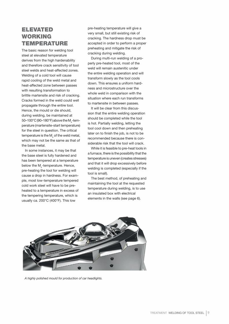
A highly polished mould for production of car headlights.
10 TREATMENT WELDING OF TOOL STEEL
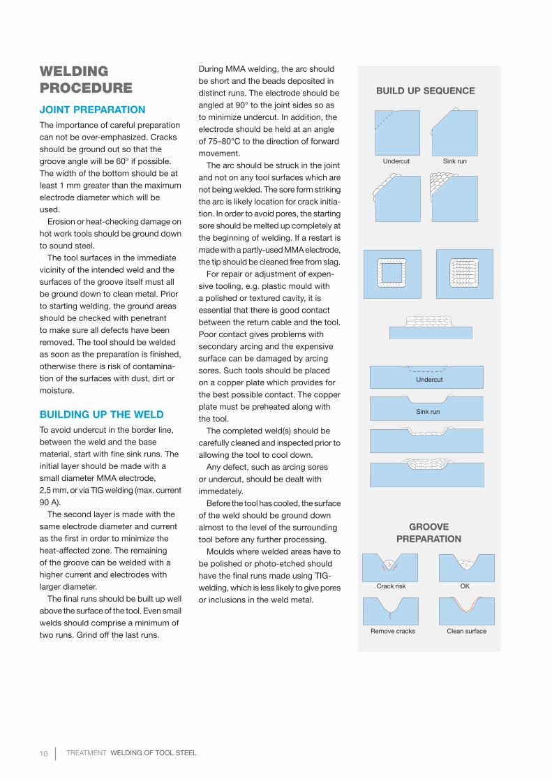
WELDING PROCEDUREJOINT PREPARATIONThe importance of careful preparation can not be over-emphasized. Cracks should be ground out so that the groove angle will be 60° if possible. The width of the bottom should be at least 1 mm greater than the maximum electrode diameter which will be used.
Erosion or heat-checking damage on hot work tools should be ground down to sound steel.
The tool surfaces in the immediate vicinity of the intended weld and the surfaces of the groove itself must all be ground down to clean metal. Prior to starting welding, the ground areas should be checked with penetrant to make sure all defects have been removed. The tool should be welded as soon as the preparation is finished, otherwise there is risk of contamina-tion of the surfaces with dust, dirt or moisture.
BUILDING UP THE WELDTo avoid undercut in the border line, between the weld and the base material, start with fine sink runs. The initial layer should be made with a small diameter MMA electrode, 2,5 mm, or via TIG welding (max. current 90 A).
The second layer is made with the same electrode diameter and current as the first in order to minimize the heat-affected zone. The remaining of the groove can be welded with a higher current and electrodes with larger diameter.
The final runs should be built up well above the surface of the tool. Even small welds should comprise a minimum of two runs. Grind off the last runs.
BUILD UP SEQUENCE
GROOVE PREPARATION
Undercut Sink run
Undercut
Sink run
Crack risk OK
Remove cracks Clean surface
During MMA welding, the arc should be short and the beads deposited in distinct runs. The electrode should be angled at 90° to the joint sides so as to minimize undercut. In addition, the electrode should be held at an angle of 75–80°C to the direction of forward movement.
The arc should be struck in the joint and not on any tool surfaces which are not being welded. The sore form striking the arc is likely location for crack initia-tion. In order to avoid pores, the starting sore should be melted up completely at the beginning of welding. If a restart is made with a partly-used MMA electrode, the tip should be cleaned free from slag.
For repair or adjustment of expen-sive tooling, e.g. plastic mould with a polished or textured cavity, it is essential that there is good contact between the return cable and the tool. Poor contact gives problems with secondary arcing and the expensive surface can be damaged by arcing sores. Such tools should be placed on a copper plate which provides for the best possible contact. The copper plate must be preheated along with the tool.
The completed weld(s) should be carefully cleaned and inspected prior to allowing the tool to cool down.
Any defect, such as arcing sores
or undercut, should be dealt with immedately.
Before the tool has cooled, the surface of the weld should be ground down almost to the level of the surrounding tool before any further processing.
Moulds where welded areas have to be polished or photo-etched should have the final runs made using TIG-welding, which is less likely to give pores or inclusions in the weld metal.
TREATMENT WELDING OF TOOL STEEL 11
cycle used is that recommended for the base steel. The welded area can then be machined and the tool may be finished and heat treated as usual. However, even if the tool can be finished by merely grinding the weld, soft annealing is first recommended in order to mitigate cracking during heat treatment.
STRESS RELIEVINGStress relieving is sometimes carried out after welding in order to reduce residual stresses. For very large or highly-constrained welds, this is an important precaution. If the weld is to be tempered or soft annealed, then stress relieving is not normally neces-sary. However, pre-hardened tool steel should be stress relieved after welding since no other heat treatment is normally performed.
The stress relieving temperature must be chosen such that neither the base steel nor the welded area soften exten-sively during the oper ation.
Very small weld repairs or adjustments will normally not require a stress reliev-ing treatment.
HEAT TREATMENT AFTER WELDINGDepending on the initial condition of the tool, the following heat treatments may be performed after welding:
• tempering
• soft annealing, then hardeningand tempering as usual
• stress relieving
TEMPERINGFully-hardened tools which are repair welded are recommended to be tempered after welding.
Tempering improves the tough- ness of the weld metal and the heat affected zone (HAZ).
The tempering temperature should be chosen so that the hardness of the weld metal and base steel are com-patible. An exception to this rule is when the weld metal exhibits appreci-ably improved temper resistance over the base material (e.g. Uddeholm Orvar Supreme welded with Udde-
FURTHER INFORMATIONInformation concerning heat treat-ment of the tool subsequent to welding can be obtained from the brochures for the welding consum-able and/or the tool steel in question.
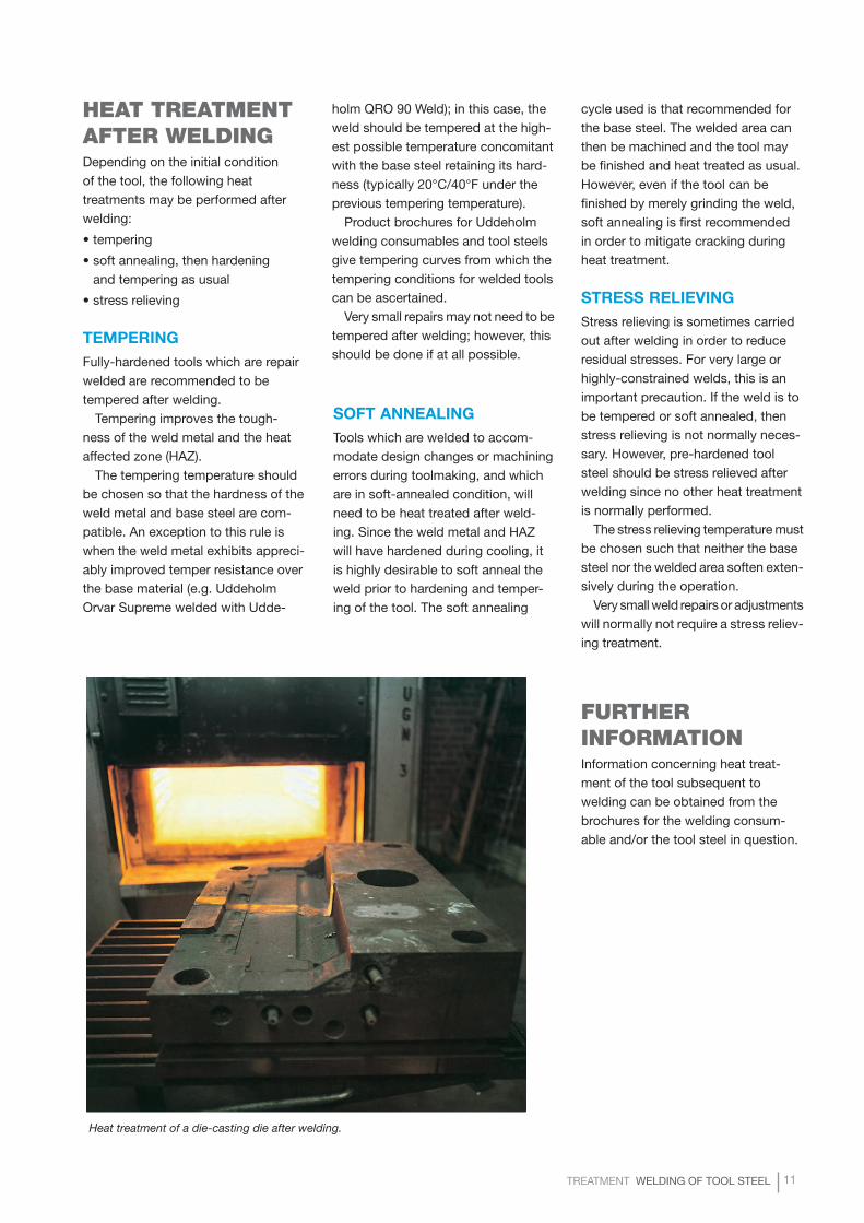
Heat treatment of a die-casting die after welding.
SOFT ANNEALINGTools which are welded to accom-modate design changes or machining errors during toolmaking, and which are in soft-annealed condition, will need to be heat treated after weld-ing. Since the weld metal and HAZ will have hardened during cooling, it is highly desirable to soft anneal the weld prior to hardening and temper-ing of the tool. The soft annealing
holm QRO 90 Weld); in this case, the weld should be tempered at the high-est possible temperature concomitant with the base steel retaining its hard-ness (typically 20°C/40°F under the previous tempering temperature).
Product brochures for Uddeholm welding consumables and tool steels give tempering curves from which the tempering conditions for welded tools can be ascertained.
Very small repairs may not need to be tempered after welding; however, this should be done if at all possible.
12 TREATMENT WELDING OF TOOL STEEL
TREATMENT WELDING OF TOOL STEEL 13
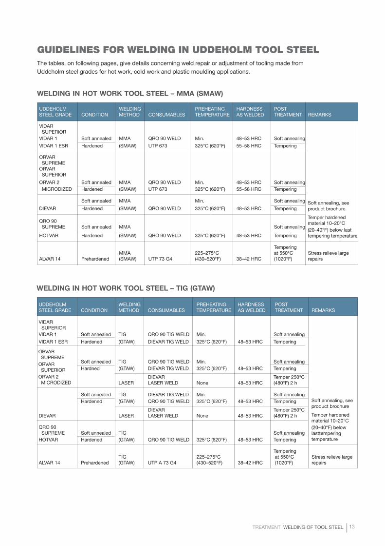
WELDING IN HOT WORK TOOL STEEL – MMA (SMAW)
GUIDELINES FOR WELDING IN UDDEHOLM TOOL STEELThe tables, on following pages, give details concerning weld repair or adjustment of tooling made from Uddeholm steel grades for hot work, cold work and plastic moulding applications.
WELDING IN HOT WORK TOOL STEEL – TIG (GTAW)
UDDEHOLM WELDING PREHEATING HARDNESS POST STEEL GRADE CONDITION METHOD CONSUMABLES TEMPERATURE AS WELDED TREATMENT REMARKS
VIDAR SUPERIOR VIDAR 1 Soft annealed TIG QRO 90 TIG WELD Min. Soft annealing
VIDAR 1 ESR Hardened (GTAW) DIEVAR TIG WELD 325°C (620°F) 48–53 HRC Tempering
Soft annealed TIG QRO 90 TIG WELD Min. Soft annealing Hardned (GTAW) DIEVAR TIG WELD 325°C (620°F) 48–53 HRC Tempering
DIEVAR Temper 250°C LASER LASER WELD None 48–53 HRC (480°F) 2 h
Soft annealed TIG DIEVAR TIG WELD Min. Soft annealing Hardened (GTAW) QRO 90 TIG WELD 325°C (620°F) 48–53 HRC Tempering
DIEVAR Temper 250°C DIEVAR LASER LASER WELD None 48–53 HRC (480°F) 2 h
QRO 90 SUPREME Soft annealed TIG Soft annealing HOTVAR Hardened (GTAW) QRO 90 TIG WELD 325°C (620°F) 48–53 HRC Tempering
TemperingTIG 225–275°C at 550°C Stress relieve large
ALVAR 14 Prehardened (GTAW) UTP A 73 G4 (430–520°F) 38–42 HRC (1020°F) repairs
UDDEHOLM WELDING PREHEATING HARDNESS POST STEEL GRADE CONDITION METHOD CONSUMABLES TEMPERATURE AS WELDED TREATMENT REMARKS
VIDAR SUPERIOR VIDAR 1 Soft annealed MMA QRO 90 WELD Min. 48–53 HRC Soft annealing
VIDAR 1 ESR Hardened (SMAW) UTP 673 325°C (620°F) 55–58 HRC Tempering
ORVAR SUPREME ORVAR SUPERIOR
ORVAR 2 Soft annealed MMA QRO 90 WELD Min. 48–53 HRC Soft annealing MICRODIZED Hardened (SMAW) UTP 673 325°C (620°F) 55–58 HRC Tempering
Soft annealed MMA Min. Soft annealing
DIEVAR Hardened (SMAW) QRO 90 WELD 325°C (620°F) 48–53 HRC Tempering
QRO 90 SUPREME Soft annealed MMA Soft annealing
HOTVAR Hardened (SMAW) QRO 90 WELD 325°C (620°F) 48–53 HRC Tempering
TemperingMMA 225–275°C at 550°C Stress relieve large
ALVAR 14 Prehardened (SMAW) UTP 73 G4 (430–520°F) 38–42 HRC (1020°F) repairs
Soft annealing, seeproduct brochure
Temper hardenedmaterial 10–20°C(20–40°F) below lasttempering temperature
Soft annealing, seeproduct brochure
Temper hardenedmaterial 10–20°C(20–40°F) below lasttempering temperature
ORVAR SUPREMEORVAR SUPERIORORVAR 2 MICRODIZED
14 TREATMENT WELDING OF TOOL STEEL
UDDEHOLM WELDING PREHEATING HARDNESS POSTSTEEL GRADE CONDITION METHOD CONSUMABLES TEMPERATURE AS WELDED TREATMENT REMARKS
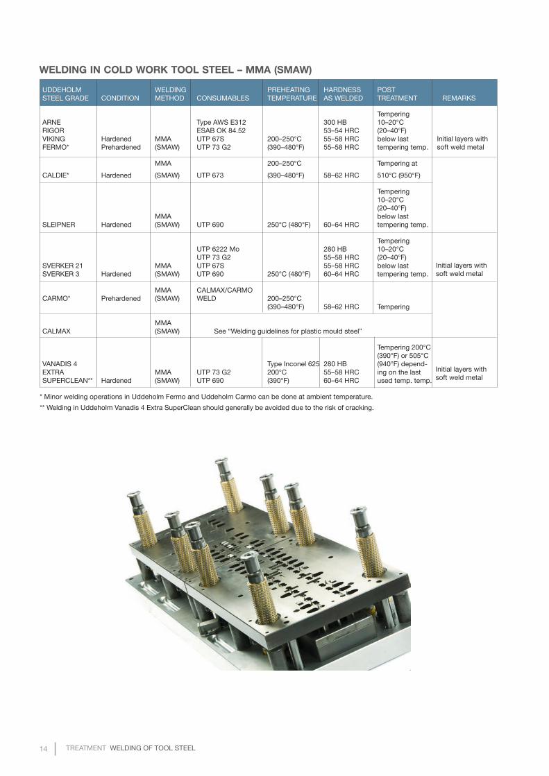
TemperingARNE Type AWS E312 300 HB 10–20°CRIGOR ESAB OK 84.52 53–54 HRC (20–40°F)VIKING Hardened MMA UTP 67S 200–250°C 55–58 HRC below lastFERMO* Prehardened (SMAW) UTP 73 G2 (390–480°F) 55–58 HRC tempering temp.
MMA 200–250°C Tempering at
CALDIE* Hardened (SMAW) UTP 673 (390–480°F) 58–62 HRC 510°C (950°F)
Tempering 10–20°C (20–40°F)
MMA below last SLEIPNER Hardened (SMAW) UTP 690 250°C (480°F) 60–64 HRC tempering temp.
Tempering UTP 6222 Mo 280 HB 10–20°C UTP 73 G2 55–58 HRC (20–40°F)
SVERKER 21 MMA UTP 67S 55–58 HRC below lastSVERKER 3 Hardened (SMAW) UTP 690 250°C (480°F) 60–64 HRC tempering temp.
MMA CALMAX/CARMOCARMO* Prehardened (SMAW) WELD 200–250°C
(390–480°F) 58–62 HRC Tempering
MMA CALMAX (SMAW) See “Welding guidelines for plastic mould steel”
Tempering 200°C (390°F) or 505°C
VANADIS 4 Type Inconel 625 280 HB (940°F) depend-EXTRA MMA UTP 73 G2 200°C 55–58 HRC ing on the lastSUPERCLEAN** Hardened (SMAW) UTP 690 (390°F) 60–64 HRC used temp. temp.
* Minor welding operations in Uddeholm Fermo and Uddeholm Carmo can be done at ambient temperature.
** Welding in Uddeholm Vanadis 4 Extra SuperClean should generally be avoided due to the risk of cracking.
WELDING IN COLD WORK TOOL STEEL – MMA (SMAW)
Initial layers with soft weld metal
Initial layers with soft weld metal
Initial layers with soft weld metal
TREATMENT WELDING OF TOOL STEEL 15
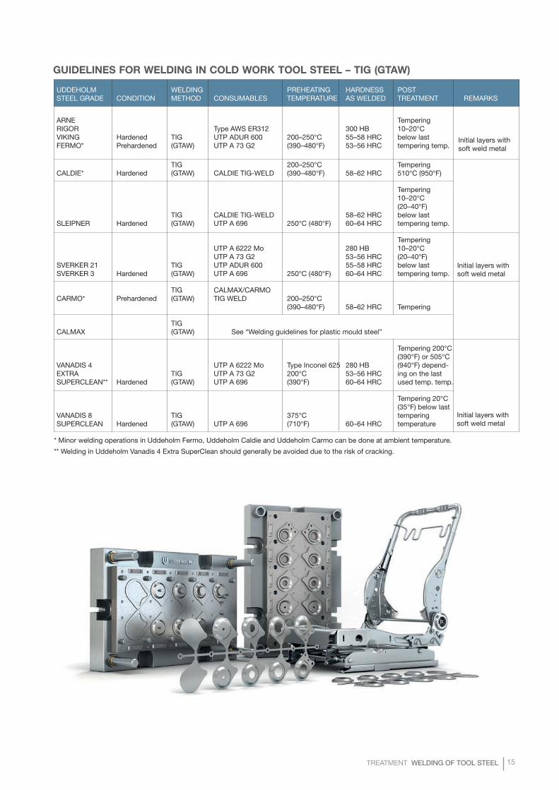
GUIDELINES FOR WELDING IN COLD WORK TOOL STEEL – TIG (GTAW)
UDDEHOLM WELDING PREHEATING HARDNESS POSTSTEEL GRADE CONDITION METHOD CONSUMABLES TEMPERATURE AS WELDED TREATMENT REMARKS
ARNE TemperingRIGOR Type AWS ER312 300 HB 10–20°CVIKING Hardened TIG UTP ADUR 600 200–250°C 55–58 HRC below lastFERMO* Prehardened (GTAW) UTP A 73 G2 (390–480°F) 53–56 HRC tempering temp.
TIG 200–250°C TemperingCALDIE* Hardened (GTAW) CALDIE TIG-WELD (390–480°F) 58–62 HRC 510°C (950°F)
Tempering 10–20°C (20–40°F)
TIG CALDIE TIG-WELD 58–62 HRC below last SLEIPNER Hardened (GTAW) UTP A 696 250°C (480°F) 60–64 HRC tempering temp.
Tempering UTP A 6222 Mo 280 HB 10–20°C UTP A 73 G2 53–56 HRC (20–40°F)
SVERKER 21 TIG UTP ADUR 600 55–58 HRC below lastSVERKER 3 Hardened (GTAW) UTP A 696 250°C (480°F) 60–64 HRC tempering temp.
TIG CALMAX/CARMOCARMO* Prehardened (GTAW) TIG WELD 200–250°C
(390–480°F) 58–62 HRC Tempering
TIG CALMAX (GTAW) See “Welding guidelines for plastic mould steel”
Tempering 200°C (390°F) or 505°C
VANADIS 4 UTP A 6222 Mo Type Inconel 625 280 HB (940°F) depend-EXTRA TIG UTP A 73 G2 200°C 53–56 HRC ing on the lastSUPERCLEAN** Hardened (GTAW) UTP A 696 (390°F) 60–64 HRC used temp. temp.
Tempering 20°C(35°F) below last
VANADIS 8 TIG 375°C tempering SUPERCLEAN Hardened (GTAW) UTP A 696 (710°F) 60–64 HRC temperature
* Minor welding operations in Uddeholm Fermo, Uddeholm Caldie and Uddeholm Carmo can be done at ambient temperature.
** Welding in Uddeholm Vanadis 4 Extra SuperClean should generally be avoided due to the risk of cracking.
Initial layers with soft weld metal
Initial layers with soft weld metal
Initial layers with soft weld metal
16 TREATMENT WELDING OF TOOL STEEL
EXAMPLE OF LASER WELDS
TREATMENT WELDING OF TOOL STEEL 17
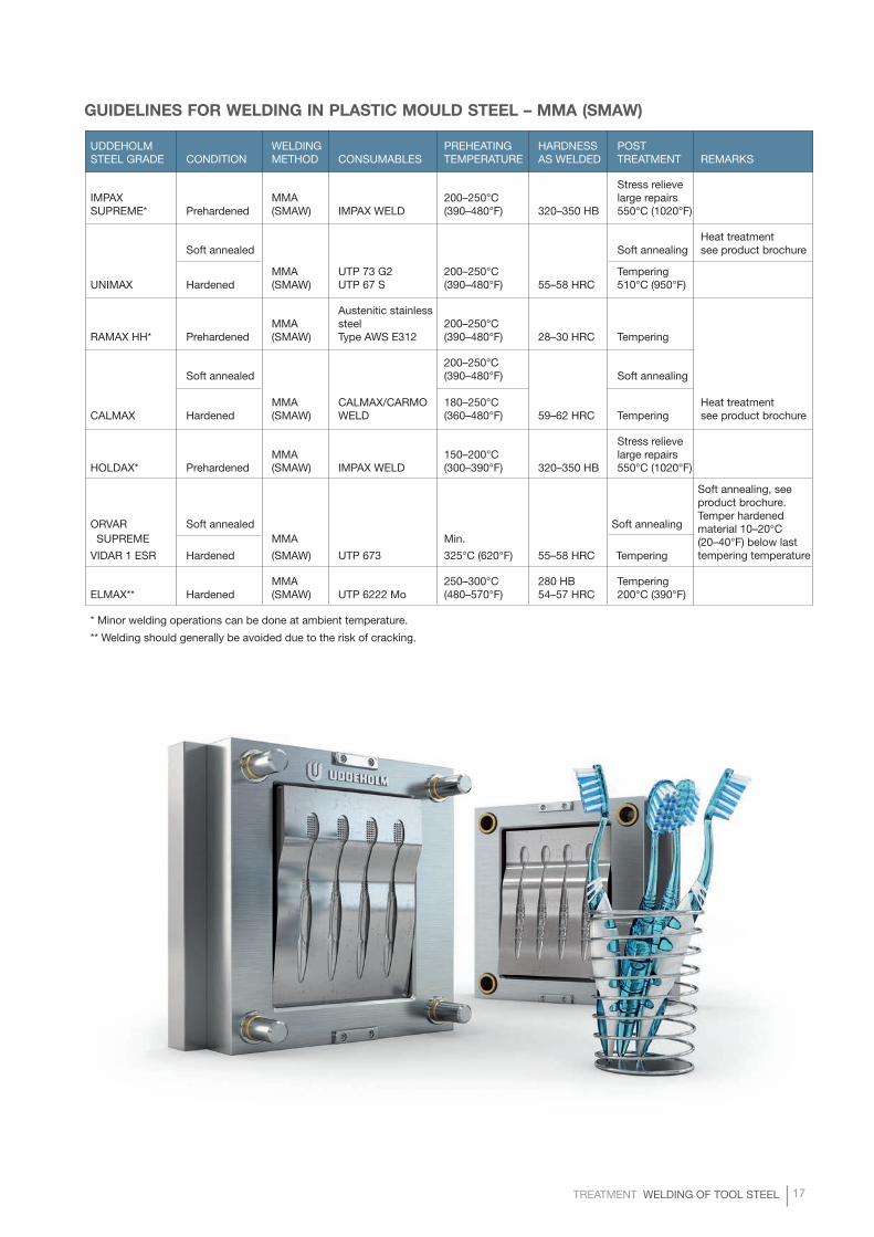
GUIDELINES FOR WELDING IN PLASTIC MOULD STEEL – MMA (SMAW)
UDDEHOLM WELDING PREHEATING HARDNESS POSTSTEEL GRADE CONDITION METHOD CONSUMABLES TEMPERATURE AS WELDED TREATMENT REMARKS
Stress relieve IMPAX MMA 200–250°C large repairs SUPREME* Prehardened (SMAW) IMPAX WELD (390–480°F) 320–350 HB 550°C (1020°F)
Heat treatment Soft annealed Soft annealing see product brochure
MMA UTP 73 G2 200–250°C Tempering UNIMAX Hardened (SMAW) UTP 67 S (390–480°F) 55–58 HRC 510°C (950°F)
Austenitic stainless MMA steel 200–250°C
RAMAX HH* Prehardened (SMAW) Type AWS E312 (390–480°F) 28–30 HRC Tempering
200–250°CSoft annealed (390–480°F) Soft annealing
MMA CALMAX/CARMO 180–250°C Heat treatment CALMAX Hardened (SMAW) WELD (360–480°F) 59–62 HRC Tempering see product brochure
Stress relieve MMA 150–200°C large repairs
HOLDAX* Prehardened (SMAW) IMPAX WELD (300–390°F) 320–350 HB 550°C (1020°F)
ORVAR Soft annealed Soft annealing SUPREME MMA Min.
VIDAR 1 ESR Hardened (SMAW) UTP 673 325°C (620°F) 55–58 HRC Tempering
MMA 250–300°C 280 HB TemperingELMAX** Hardened (SMAW) UTP 6222 Mo (480–570°F) 54–57 HRC 200°C (390°F)
* Minor welding operations can be done at ambient temperature.
** Welding should generally be avoided due to the risk of cracking.
Soft annealing, seeproduct brochure.Temper hardenedmaterial 10–20°C(20–40°F) below lasttempering temperature
18 TREATMENT WELDING OF TOOL STEEL
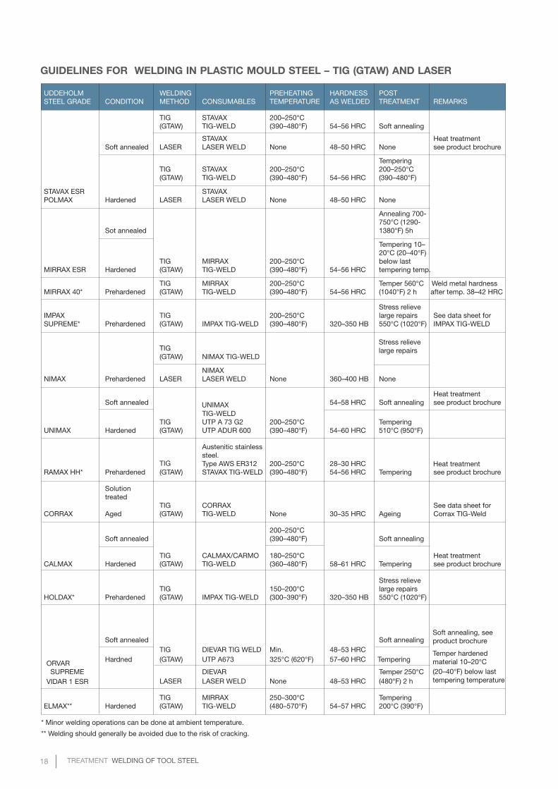
GUIDELINES FOR WELDING IN PLASTIC MOULD STEEL – TIG (GTAW) AND LASER
TIG Heat treatment
UNIMAX
Soft annealing, seeproduct brochure
Temper hardenedmaterial 10–20°C(20–40°F) below lasttempering temperature
Stress relievelarge repairs
UDDEHOLM WELDING PREHEATING HARDNESS POSTSTEEL GRADE CONDITION METHOD CONSUMABLES TEMPERATURE AS WELDED TREATMENT REMARKS
TIG STAVAX 200–250°C (GTAW) TIG-WELD (390–480°F) 54–56 HRC Soft annealing
STAVAX Heat treatment Soft annealed LASER LASER WELD None 48–50 HRC None see product brochure
TemperingTIG STAVAX 200–250°C 200–250°C (GTAW) TIG-WELD (390–480°F) 54–56 HRC (390–480°F)
STAVAX ESR STAVAX POLMAX Hardened LASER LASER WELD None 48–50 HRC None
Annealing 700- 750°C (1290-
Sot annealed 1380°F) 5h
Tempering 10– 20°C (20–40°F)
TIG MIRRAX 200–250°C below last MIRRAX ESR Hardened (GTAW) TIG-WELD (390–480°F) 54–56 HRC tempering temp.
TIG MIRRAX 200–250°C Temper 560°C Weld metal hardness MIRRAX 40* Prehardened (GTAW) TIG-WELD (390–480°F) 54–56 HRC (1040°F) 2 h after temp. 38–42 HRC
Stress relieveIMPAX TIG 200–250°C large repairs See data sheet for SUPREME* Prehardened (GTAW) IMPAX TIG-WELD (390–480°F) 320–350 HB 550°C (1020°F) IMPAX TIG-WELD
TIG (GTAW) NIMAX TIG-WELD
NIMAX NIMAX Prehardened LASER LASER WELD None 360–400 HB None
Heat treatment Soft annealed 54–58 HRC Soft annealing see product brochure
TIG-WELD TIG UTP A 73 G2 200–250°C Tempering
UNIMAX Hardened (GTAW) UTP ADUR 600 (390–480°F) 54–60 HRC 510°C (950°F)
Austenitic stainlesssteel.
Type AWS ER312 200–250°C 28–30 HRC RAMAX HH* Prehardened (GTAW) STAVAX TIG-WELD (390–480°F) 54–56 HRC Tempering see product brochure
Solutiontreated
TIG CORRAX See data sheet for CORRAX Aged (GTAW) TIG-WELD None 30–35 HRC Ageing Corrax TIG-Weld
200–250°CSoft annealed (390–480°F) Soft annealing
TIG CALMAX/CARMO 180–250°C Heat treatment CALMAX Hardened (GTAW) TIG-WELD (360–480°F) 58–61 HRC Tempering see product brochure
Stress relieve TIG 150–200°C large repairs
HOLDAX* Prehardened (GTAW) IMPAX TIG-WELD (300–390°F) 320–350 HB 550°C (1020°F)
Soft annealed Soft annealing TIG DIEVAR TIG WELD Min. 48–53 HRC
Hardned (GTAW) UTP A673 325°C (620°F) 57–60 HRC Tempering
DIEVAR Temper 250°C LASER LASER WELD None 48–53 HRC (480°F) 2 h
TIG MIRRAX 250–300°C TemperingELMAX** Hardened (GTAW) TIG-WELD (480–570°F) 54–57 HRC 200°C (390°F)
* Minor welding operations can be done at ambient temperature.
** Welding should generally be avoided due to the risk of cracking.
ORVAR SUPREMEVIDAR 1 ESR

TREATMENT WELDING OF TOOL STEEL 19
NETWORK OF EXCELLENCEUddeholm is present on every continent. This ensures you
high-quality Swedish tool steel and local support wherever
you are. Our goal is clear – to be your number one partner
and tool steel provider.

20 TREATMENT WELDING OF TOOL STEEL
UD
DEH
OLM
10.2017.200 / STROKIRK-LAN
DSTRÖ
MS, Karlstad
Uddeholm is the world’s leading supplier of tooling materials.
This is a position we have reached by improving our customers’
everyday business. Long tradition combined with research and
product development equips Uddeholm to solve any tooling problem
that may arise. It is a challenging process, but the goal is clear –
to be your number one partner and tool steel provider.
Our presence on every continent guarantees you the same high
quality wherever you are. We act worldwide. For us it is all a matter
of trust – in long-term partnerships as well as in developing new
products.
For more information, please visit www.uddeholm.com