welding lecture - 9mech14.weebly.com/.../welding_lectures_9-11.pdf · 7 7 resistance spot welding...
TRANSCRIPT

1 1
Welding Processes-Resistance welding
Welding Lecture - 9 16 August 2016, Tuesday 11.00 -11.50 am

2 2
Resistance welding (RW) • Generate heat through the
resistance to the flow of electric current in parts being welded
• The parts are usually an integral part of the electrical circuit
• Contact resistance → heats the area locally by I2R, → melting → formation of a nugget
• Contact resistance must be higher at the point to be welded than anywhere else.

3 3
Resistance welding

4
Resistance welding

5 5
Resistance welding • Pairs of water-cooled copper electrodes • Apply pressure
– To reduce the contact resistance at the electrode-to-workpiece interface
– Contain the molten metal in the nugget – To literally forge the work surfaces together in the vicinity of the weld
• The principal process variables – welding current (several thousands to tens of thousands of amperes) – welding time (of the order of s) – electrode force and electrode shape
• DC power (provided from either single-phase or three-phase AC line 440-480 V using step-down transformer/rectifiers)
• Usually used to join overlapping sheets or plates as lap joints, which may have different thicknesses

6 6
Resistance welding-types
• Resistance spot welding (RSW) • Resistance seam welding (RSEW) • Projection welding (PW) • Flash welding (FW) • Upset welding (UW) • Percussion welding (PEW)

7 7
Resistance spot welding (RSW) • Series of discrete nuggets
produced by resistance heating
• Nuggets (welds) are usually produced directly under the electrodes, → Not necessarily if there is another more favourable path (shunt), for the current

8 8
Series resistance spot welding

9
Resistance welding cycle • Squeeze Time: Time interval between timer initiation
and the first application of current needed to assure that electrodes contact the work and establish full force
• Weld time: The time for which welding current is applied (in single impulse welding) to the work
• Hold Time: The time during which force is maintained on the work after the last impulse of welding current ends to allow the weld nugget to solidify and develop strength.
• Off Time: The time during which the electrodes are off the work and the work is moved to the next weld location for repetitive welding.

10 10
Pressure-current cycle

11 11
Pressure-current cycle
1. Off time: Parts inserted between open electrodes, 2. Squeeze Time:Electrodes close and force is
applied, 3. Weld time— current is switched on, 4. Hold time: Current is turned off but force is
maintained or increased (a reduced current is sometimes applied near the end of this step for stress relief in the weld region), and
5. Off time: Electrodes are opened, and the welded assembly is removed.

12
Enhanced welding cycle 1. Pre-compression force is used to set electrodes
and work pieces together 2. Preheat is applied to reduce thermal gradients at
the start of weld time or to soften coatings 3. Forging force is used to consolidate weld nugget 4. Quench and temper times are used to produce
desired weld properties in hardenable steels; 5. Post heat is used to refine weld nugget grain size
and improve strength 6. Current decay is used to retard cooling of
aluminum alloys to help prevent cracking

13
Enhanced resistance welding cycle

14
Nugget formation
Nugget formation and heat dissipation into the surrounding base metal and electrodes during resistance spot welding

15
Optimum current, time in RW
• Optimum current and weld time for maximum shear strength of the RW joint

16 16
Resistance seam welding
Conventional resistance seam welding, in which overlapping spots
are produced
Roll spot welding
Continuous resistance
seam

Resistance seam welding
17

18 18
Mash seam weld

19 19
Projection welding (PW),
• Projections or dimples in overlapping joint elements → concentrate the current during welding, focusing the weld energy and helping to locate the weld more precisely
• Contact points determined by the design of the parts to be joined → may consist of projections, embossments, or localized intersections of the parts

20 20
Flash welding(FW)
1. Normally used for butt joints → the two surfaces to be joined are brought into near contact →
2. Electric current is applied →Arcing → Heats the surfaces to the melting point → the surfaces are forced together to form the weld

21 21
Upset welding (UW) • Upset welding (UW) is
similar to flash welding • Heating in UW is
accomplished entirely by electrical resistance at the contacting surfaces; no arcing occurs.
• Not a fusion-welding process
• Applications of UW & FW- joining ends of wire, pipes, tubes etc.

22 22
Percussion welding
• Resistance heating by the rapid release of electrical energy from a storage device (e.g., capacitor).
• Similar to flash welding, except that the duration of the weld cycle is extremely short, ~ 1 to 10 ms
• Very localized heating → attractive for electronic applications in which the dimensions are very small

23 23 23
Heat flow in welds
Welding Lecture - 10 23 August 2016, Tuesday 11.00 -11.50 am

24
The welding thermal cycle • Thermal excursion→ Weld temp. ranges from the
ambient temp. of the work environment to above the liquidus temp. (possibly to boiling point and above for some very high-energy-density processes)
• The severity of this excursion → in terms of the – temp. reached – time taken to reach them – the time remain at them completely determines the effects on structure (both
microstructural for material changes and macrostructural for distortion)
• To quantify the thermal cycle mathematically, we need temp. distribution in time and space co-ordinates
25
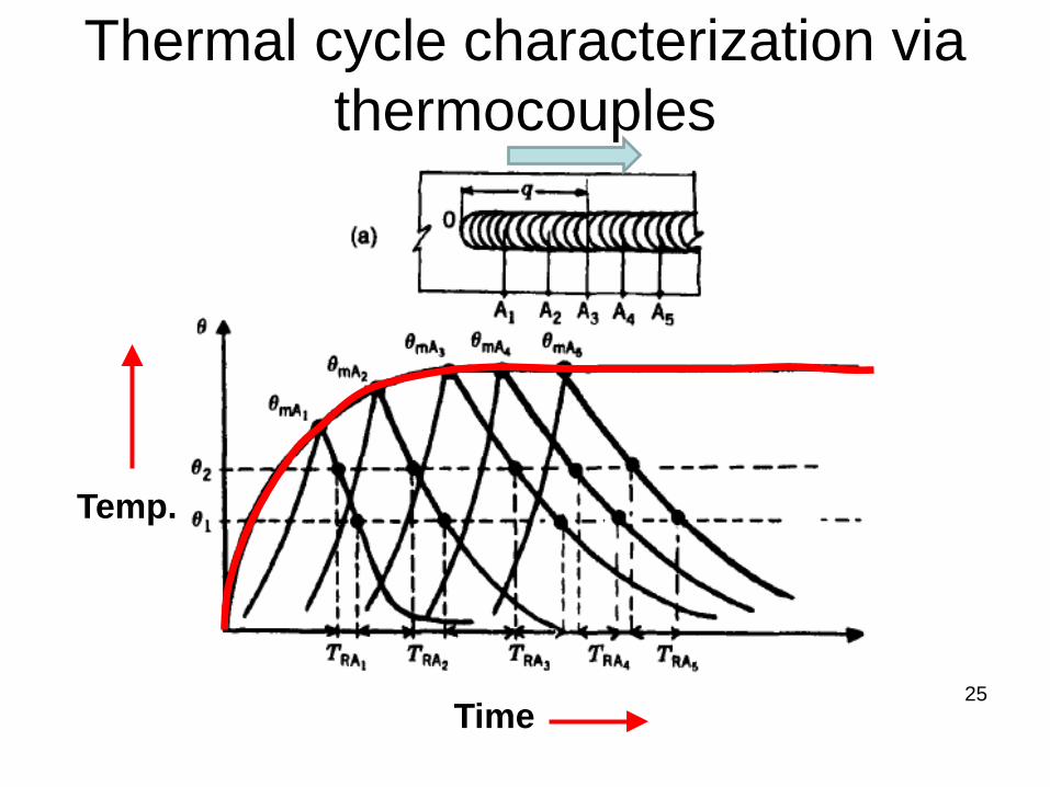
Thermal cycle characterization via thermocouples
Time
Temp.
26
Thermal cycle- quasi-steady state • Thermocouples → at various points along weld path • Approach of the heat source → rapid rise in
temperature to a peak → a very short hold at that peak → then a rapid drop in temperature once the source has passed by
• A short time after the heat from the source begins being deposited, → the peak temperature & rest of the thermal cycle, reaches a quasi-steady state
• Quasi-steady state → balance achieved between the rate of energy input and the rate of energy loss or dissipation
• Quasi-steady state → temperature isotherms surrounding a moving heat source remain steady and seem to move with the heat source (away from edges)

27
Thermal cycle- quasi-steady state
Temperature isotherms surrounding a moving heat source remain steady and seem to move with the heat source
S Fusion zone
HAZ

28
Time-Temperature curves
Time
Temperature
θ p Time= Ti (where Ti>To)

29
Time-Temperature curves • The peak temp. decrease with increasing distance from
the source, and more or less abruptly • The maximum temperatures reached (TmA TmB, Tmc)
decrease with distance from the weld line and occur at times (tmA, tmB, tmc) that increase. This allows the peak temperature, Tp to be plotted as a function of time
• Peak temp. separates the heating portion of the welding thermal cycle from the cooling portion,
• At a time when points closest to a weld start cooling, the points farther away are still undergoing heating. This phenomenon explains – certain aspects of phase transformations that go on in the
heat-affected zone, – differential rates of thermal expansion/contraction that
lead to thermally induced stresses and, possibly, distortion

30
Spatial isotherms Tp (Peak temperature)
Heating zone
Heating zone Cooling zone
Cooling zone
• Peak temperature separates the heating zone & cooling zone
31
The generalized heat flow equation • Temp. distribution→ Controls microstructure,
residual stresses and distortions, and chemical reactions (e.g., oxidation)
• The influencing parameters – the solidification rate of the weld metal, – the distribution of peak temperature in the HAZ – the cooling rates in the fusion and HAZ – the distribution of heat between the fusion zone
and the heat-affected zone • Requires mathematical formulation to
quantify the influence of these parameters

32
The generalized heat flow equation
Heat supplied + Heat generated /Absorbed (chemical reaction) = Heat consumed (for temp rise, melting) + Heat transferred via conduction + Heat loss via convection & radiation

33
The generalized heat flow equation
x = coordinate in the direction of welding (mm) y = coordinate transverse to the welding direction (mm) z = coordinate normal to weldment surface (mm) T = temperature of the weldment, (K) k(T) = thermal conductivity of the material (J/mm s-1K-1) as a
function of temperature ρ(T) = density of the material (g/mm3) as a function of temp. C(T) = specific heat of the material (J/g-1 K-1), as a function of
temperature Vx, Vy, and Vz = components of velocity Q = rate of any internal heat generation, (W/mm3)

34
The generalized heat flow equation • This general equation needs to be solved for one, two, or
three dimensions depends on – Weld geometry, – Whether the weld penetrates fully or partially – Parallel sided or tapered, and – Relative plate thickness
• 1-D solution → thin plate or sheet with a stationary source or for welding under steady state (at constant speed and in uniform cross sections remote from edges) in very thin weldments
• 2-D solution → thin weldments or in thicker weldments where the weld is full penetration and parallel-sided (as in EBW) to assess both longitudinal and transverse heat flow
• 3-D solution → thick weldment in which the weld is partial penetration or non-parallel-sided (as is the case for most single or multipass welds made with an arc source)

35
Weld geometry and dimensionality of heat flow
(a)2-D heat flow for full-penetration welds in thin plates or sheets;
(b)2-D heat flow for full-penetration welds with parallel sides (e.g. EBW & LBW)
(c)3-D heat flow for partial penetration welds in thick plate
(d)3D, condition for near-full penetration welds (non parallel sides)

36
• Rosenthal’s first critical assumption → Energy input from the heat source was uniform and moved with a constant velocity v along the x-axis of a fixed rectangular coordinate system
• The net heat input to the weld under theseconditions is given by
Hnet = ηEI/v (J/m) where η is the the transfer efficiency of the process E
and I are the welding voltage (in V) and current (in A), respectively, and v is the velocity of welding or travel speed (in m/s).
Rosenthal’s Simplified Approach

37
Rosenthal’s Simplified Approach
Assumption 2 → Heat source is a point source, with all of the energy being deposited into the weld at a single point – This assumption avoids complexities with density distribution of
the energy from different sources and restricts heat flow analysis to the heat-affected zone, beyond the fusion zone or weld pool boundary.
Assumption 3 → The thermal properties (thermal conductivity, k, and product of the specific heat and density, Cp) of the material being welded are constants
Assumption 4 → Modify the coordinate system from a fixed system to a moving system

38
Rosenthal’s Simplified Approach
• The moving coordinate system → replace x with ξ (Xi), where ξ is the distance of the point heat source from some fixed position along the x axis, depending on the velocity of welding, v
ξ=x-vt where t is the time

39
Rosenthal’s Simplified Approach
• This equation can be further simplified, in accordance with Rosenthal, if a quasi-stationary temperature distribution exists.
• Temperature distribution around a point heat source moving at constant velocity will settle down to a steady form, such that dT/dt = 0, for q/v = a constant. The result is

40
Rosenthal’s solution • Rosenthal solved the simplified form of the heat flow
equation above for both thin and thick plates in which the heat flow is basically 2-D and 3-D, respectively.
• For thin plates,
q = ηEI/v = heat input from the welding source (in J/m) k = thermal conductivity (in J/m s-1 K-1) α = thermal diffusivity = k/pC, (in m/s) R = (ξ2 + y2 + z2)1/2, the distance from the heat source to a particular fixed point (in m) K0 = a Bessel function of the first kind, zero order
1

41
Rosenthal’s solution
• For the thick plate,
where d = depth of the weld (which for symmetrical welds is half of the weld width, since w = 2d)
2

42
Rosenthal’s solution
• Above equations can each be written in a simpler form, giving the time-temperature distribution around a weld when the position from the weld centerline is defined by a radial distance, r, where r2 = z2 + y2
• For the thin plate, the time-temperature distribution is

43
Dimensionless Weld Depth Vs Dimensionless Operating
Parameter • Based on Rosenthal’s solution of the simplified three-
dimensional heat flow equation, Christiansen et al. (1965) derived theoretical relationships between a weld bead’s cross-sectional geometry and the welding process operating conditions using dimensionless parameters.
• The theoretical relationship between the dimensionless weld width, D, and dimensionless operating parameter, n, is shown, where

44
Dimensionless Weld Depth Vs Operating Parameter n
d = depth of penetration of the weld, U = welding speed (m/s), αs = thermal diffusivity (k/ρC) of the base material (as a solid), Q = rate of heat input to the workpiece (J/s), Tm = melting point of the base material (the workpiece), and To = temperature of the workpiece at the start of welding. For a symmetrical weld bead, the width of the weld bead w = 2d, → Cross-sectional area of the weld bead can be determined
Can be applied to the heat-affected zone by simply substituting TH for Tm where TH is the temperature of some relevant phase transformation that could take place

45
Dimensionless weld depth (D) Vs process operating parameter n
• Width of the weld bead can be determined (w = 2d) • Width of heat-affected zone can be determined
Christiansen (1965)

Class Assignment -1
46
1) Find w and d for symmetrical weld bead as shown in figure.
2) Find the width of HAZ (phase transition temp = 730 C) Material steel with Tm= 1510 C E=20 V I= 200 A Welding speed (v or U) =5 mm/s T0= 25 C Arc efficiency η=0.9 K=40 W/mK ρC = 0.0044 J/mm3. C t=5 mm
w
d

47
Effect of welding parameters on heat distribution
• The shape of the melt , size & heat distribution, is a function of 1. Material properties (thermal conductivity, heat
capacity, density) 2. Welding speed, and 3. Welding power/energy density 4. Weldment plate thickness

48
Effect of thermal conductivity (and material property) on heat distribution
• Increasing thermal conductivity – tends to cause deposited heat to spread – Smaller welds for a given heat input and
melting temperature • For a given heat input, the lower the
melting point, the larger the weld

49
Effect of thermal conductivity (and material property) on heat distribution
Material Thermal diffusivity
α=k/ρC (mm2/s)
Aluminium 84
Carbon steel 12
Austenitic steel
4

50
Effect of welding speed

Effect of welding speed on Shape of Fusion/HAZ
Velocity
0 Low Medium High Very high
Plan view
Circle elliptical Elongated ellipse
Tear drop
Detached tear drop
3-D view
Hemi-spherical
Prolate spheroidal
Elongated prolate
spheroidal
3D tear drop
3D tear drop
Increasing velocity
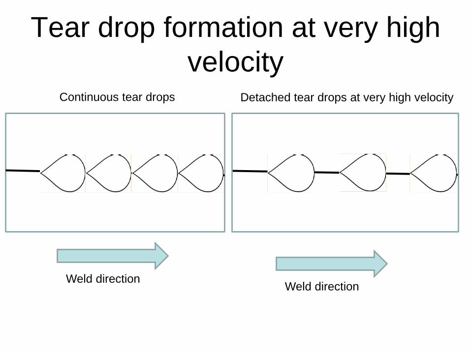
Tear drop formation at very high velocity
Weld direction Weld direction
Detached tear drops at very high velocity Continuous tear drops

53
Effect of welding speed
• For a stationary (spot) weld, the shape, is round (plan view), and approximately hemispherical in 3-D
• Once the source is moved with constant velocity, the weld pool and surrounding HAZ become elongated to an elliptical shape (plan view), and prolate spheroidal in 3-D
• With increased velocity, these zones become more and more elliptical
• At some velocity (for each specific material), a tear drop shape forms, with a tail at the trailing end of the pool.

54
Effect of welding speed
• Increasing velocity → elongates the teardrop more and more, → narrows the fusion and heat-affected zone → overall melted volume constant
• Very high welding speeds → the tail of the teardrop weld pool detaches → isolate regions of molten metal → lead to shrinkage-induced cracks along the centerline of the weld

55
Efect of the thickness of a weldment
•Thick weldment → Small weld pool and heat-affected zone

56
Effect of energy density, Asymmetry
• Increased energy density → increases the efficiency of melting, → increases the amount of melting (especially in the depth direction) → decreases the heat-affected zone.
• Shape of weld pool & HAZ will be distorted by any asymmetry around the joint.
• Asymmetry might be the result of the relative thermal mass (e.g., thickness) of the joint elements as well as their relative thermal properties (Tm, k & C)

57
Simplified Equations for Approximating Welding Conditions
1) Peak Temperatures → Predicting metallurgical transformations (melting, austenitization, recrystallization of cold-worked material, etc.) at a point in the solid material near a weld requires some knowledge of the maximum temperature reached at that specific location.
→ For a single-pass, full-penetration butt weld in a sheet or a plate, the distribution of peak temperatures (Tp) in the base material adjacent to the weld is given by

58
Peak Temperature
To = initial temperature of the weldment (K) e = base of natural logarithms = 2.718 ρ = density of the base material (g/mm3) C = specific heat of the base material (J/g K- I) h = thickness of the base material (mm) y = 0 at the fusion zone boundary and where Tp = Tm Tm = melting (or liquidus) temperature of the material
being welded (K) Hnet = ηEI/v (J/m)

59
Width of the Heat-Affected Zone • Peak temperature equation can be used to
calculate the width of the HAZ. • Define Tp → Tre or Tau • The width of the HAZ is determined by the value of
y that yields a Tp equal to the pertinent transformation temperature (recrystallization temperature, austenitizing temperature, etc.).
• Equation cannot be used to estimate the width of the fusion zone, since it becomes unsolvable when Tp =Tm
• (Remember the assumption in Rosenthal’s solution of the generalized equation of heat flow, → Heat was deposited at a point, and there was no melted region, but just a HAZ)

60
Assignment 2
a) Calculate the peak temperatures at distances of 1.5 and 3.0 mm from the weld fusion boundary b) Calculate the width of HAZ if the recrystallization temperature is 730° C c) Find the influence on the width of HAZ if a preheated sample is used (Assume preheat temp =200° C) d) Find the influence on the width of HAZ if the net energy is increased by 10% e) Find the influence on the width of HAZ if the velocity is increased to 10 mm/s
A single full penetration weld pass is made on steel using the following parameters. Tm= 1510 C, E=20 V, I= 200 A, Welding speed (v or U) =5 mm/s, T0= 25 C, Arc efficiency =0.9, ρC = 0.0044 J/mm3. C, t=5 mm, Hnet= 720 J/mm