weight functions method for stability analysis applied as design … · 2016-10-20 · botez &...
TRANSCRIPT

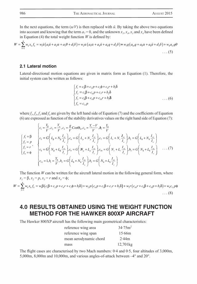
ABSTRACTA new method for system stability analysis, the weight functions method, is applied to estimate the longitudinal and lateral stability of a Hawker 800XP aircraft. This paper assesses the application of the weight functions method to a real aircraft and a method validation with an eigenvalues stability analysis of the linear small-perturbation equations. The method consists of finding the weight functions that are equal to the number of differential equations required for system modelling. The aircraft’s stability is determined from the sign of the total weight function – the sign should be negative for a stable model. Aerodynamic coefficients and stability derivatives of the mid-size twin-engine corporate aircraft Hawker 800XP are obtained using the in-house FDerivatives code, recently developed at our laboratory of applied research in active controls, avionics and aeroservoelasticity LARCASE. The results are validated with the flight test data supplied by CAE Inc. for all considered flight cases. This aircraft model was chosen because it was part of a research project for FDerivatives code and continued with weight function method for stability analysis in order to develop a design tool, based only on the aircraft geometrical parameters for subsonic regime. The following flight cases are considered: Mach numbers = 0·4 and 0·5, altitudes = 3,000m, 5,000m, 8,000m and 10,000m, and angles-of-attack α = –5° to 20°.
NOMENCLATUREAoA angle-of-attackb wing spanc wing mean aerodynamic chordIx,Iy,Iz moment of inertia about the X, Y and Z body axes, respectivelyIxz product of inertia
The AeronAuTicAl JournAl AugusT 2015 Volume 119 no 1218 981
Paper No. 4087. Manuscript received 8 October 2013, revised version received 15 January 2015, accepted 3 March 2015.
Weight functions method for stability analysis applied as design tool for Hawker 800XP aircraftN. AntonR. M. Botez [email protected]École de technologie supérieure Laboratory of Research in Active Controls, Aeroservoelasticity and Avionics Montréal Canada

982 The AeronAuTicAl JournAl AugusT 2015
Lp rolling moment due to roll rate Lr rolling moment due to yaw rateLβ rolling moment due to sideslipLδ roll control derivativem aircraft mass M Mach numberMq pitching moment due to pitch rateMu pitching moment increment with increased speed Mα pitching moment due to incidenceMα pitching moment due to rate of change of the incidenceMδ pitching moment due to flap deflectionNp yawing moment due to roll rateNr yawing moment due to yaw rateNβ yawing moment due to sideslipNδ yawing moment due to flap deflectionp,q,r angular rates about the X, Y and Z body axes, respectivelyp,q,r time rate of change of p,q,rq dynamic pressureS wing areau axial velocity perturbationu time rate of change of uV airspeedXu drag increment with increased speedXα drag due to incidenceXδ drag due to flap deflectionYp side force due to roll rateYr side force due to yaw rateYβ side force due to sideslipYδ side force control derivativeZq lift due to pitch rateZu lift due to speed incrementZα lift due to incidenceZα lift due to the rate of change of incidenceZδ lift due to flap deflectionα angle-of-attackα,β,θ time rate of change of α, β, θβ sideslip angleδ control deflectionδa aileron deflectionδe elevator deflectionφ roll angleλp phugoid eigenvaluesλsp short-period eigenvaluesωnp phugoid modal frequencyωnsp short-period modal frequency θ pitch angleζp phugoid natural damping
.
.
.
. . .
.
. .

BoTez & AnTon WeighT funcTions meThod for sTABiliTy AnAlysis Applied As design Tool for 983
ζsp short-period natural dampingψ yawing angle
1.0 INTRODUCTIONThe stability analysis for a real aircraft was done in this paper using the longitudinal and the lateral-directional motion mathematical model. The midsize Hawker 800XP is a twin-engine corporate aircraft with low swept-back one-piece wings, a high tail plane and rear-mounted engines. The aircraft has a maximum Mach number of 0·9. The flight test data was provided by CAE Inc. A new method for systems stability analysis, the weight function method, was used to replace the use of Lyapunov functions. The method can be used as a design analysis tool because it can be applied if the aircraft’s geometrical parameters are known, which is true also fo r eigenvalue analysis.
Weight Function Method (WFM) was used in literature mostly for determination of stress factors for crack problems. The method was applied by Yoichi et al(1) to solve two- and three-dimensional crack problems and to calculate stress intensity factors for arbitrary loading conditions and the stress intensity factor for the patched crack within an infinite plate was successfully numerically validated using the WFM(2). Different formula to calculate the stress intensity factor are presented in Refs 3-4.
A different approach was presented by Stroe(7), who solved the Lurie-Postnikov problem using general equations for linear or nonlinear vibrations by linear transformations. Stroe also analysed a holonomic system with dependent variable equations(8) where the weight functions method was applied for vibration and stability studies in the cases of linear and nonlinear damped holonomic systems.
The selections of H∞ weighting functions were presented for practical applications by Jiankun et al(9), where the authors showed that an H∞ weighting function for a single-input single-output system could be obtained by considering it as a series of connections of elementary low-order systems. For a constrained control effort, an explicit weighting function was obtained. They proposed a novel method for the selection of weighting functions in an H∞ mixed sensitivity design to directly control the percentage overshoot. Real-time experimental results were presented for the roll-angle control of a laboratory scale model of a vertical take-off aircraft.
The WFM was applied in the aerospace industry only for the modelling of the longitudinal motion of a canard configuration generic fighter aircraft, called the High Incidence Research Model (HIRM) by the main author of this paper, Anton(10). The HIRM, a non-linear aircraft model developed by FOI Swedish Defense Research Agency, based on the Generic Aerodata Model (GAM) developed by SAAB AB, has been the subject of collaboration within the Group for Aeronautical Research and Technology in EURope (GARTEUR Action Group FM (AG08)). Results were presented for a complete range of angle-of-attack (–10 to 30)° and elevon deflection angle (–30 to 30)°, constant value of Mach number of 0·25, altitude 500m. The WFM was applied in the case of short-period longitudinal approximations for the system of equations with unstable characteristics given by the pitching-moment coefficients, and the aircraft model was stabilised using control laws. The stability field was augmented from a maximum controllable angle-of-attack equal to 10·9 degrees to 26 degrees. This model had increased complexity because the thrust component was included in the system equations.
In this paper, the weight functions method (WFM) and the eigenvalues stability method are applied to study the Hawker 800XP aircraft’s stability, based on aerodynamics coefficients and their derivatives provided by FDerivatives code(13). This is the first time that the weight functions method is being used to analyse longitudinal and lateral aircraft model stability. The WFM is used here to determine the total aircraft model stability of a mid-size business aircraft with a typical wing-body-tail configuration and three basic control surfaces: the ailerons, elevator and rudder, designed to change and control the moments about the reference axis. This airplane has swept-back wings that are used to delay the drag divergence.

984 The AeronAuTicAl JournAl AugusT 2015
The results, expressed in terms of weighting functions for the Weighting Functions Method (WFM), and in terms of damping and frequency for the eigenvalues method, are presented for the subsonic regime characterised by Mach numbers equal to 0·4 and 0·5, and four altitudes: 3,000m, 5,000m, 8,000m and 10,000m. The pitch angles θ = (–20 to 20)° and pitch rates q = (–3·5 to 3·5)°/s are the longitudinal motion variables, and the roll rate p = (–6 to 6)°/s, yaw rate r = (–2 to 2)°/s, sideslip angle β = (–5 to 5)° and roll angle Φ = (–15 to 15)° are the variables for lateral motion. It was also considered that we have a value δ = 5° for the control term. In the following sections, the WFM and root locus method are described and the related results using both methods are presented.
2.0 THE WEIGHT FUNCTIONS METHODQuadratic forms have a matrix representation and its studying is reduced to studying of symmetric matrices. Consider the function F: R2→R, where F = a11x12 + a12x1x2 + a22x22
(11). This quadratic form in Rn is where x = (x1, ..., xn), and the matrix A is unique and n × n symmetric
matrix. The matrix A is:1) positive definite if F(x) > 0, for x ≠ 0 in Rn. x = 0 is a unique global minimum of the quadratic
form given by A.
2) positive semidefinite if F(x) ≥ 0, for x ≠ 0 in Rn. x = 0 is a global minimum, but not a unique global one, of the quadratic form given by A.
3) negative definite if F(x) < 0, for x ≠ 0 in Rn. x = 0 is a unique global maximum of the quadratic form given by A.
4) negative semidefinite if F(x) ≤ 0, for x ≠ 0 in Rn. x = 0 is a global maximum, but not a unique global one, of the quadratic form given by A.
5) indefinite if F(x) > 0, for some x Rn and < 0 for some other x Rn. x = 0 is neither a maximum nor a minimum of the quadratic form given by A.
In most practical problems, differential equations that model the behaviour of a dynamic system often depend on more than one parameter. For example, the WFM is more efficient than the classical Lyapunov functions method since only one function has to be found at a time, while the Lyapunov method finds all functions simultaneously. In fact, the Lyapunov stability criteria are based on finding only one Lyapunov function. Finding a Lyapunov function is not simple and is not guaranteed.
The WFM finds a number of weight functions that is equal to the number of the first-order differential equations modelling the system(7,8).
Theorem(8): Given the autonomous system x = f (x) , x ∈ Rn, if wk (x1, x2... xn) exist such thatis a total exact differential, then the stability is given by as follows: W is negative-
definite , the solution is asymptotic stable; W is the null function, the solution is simple stable; W is positive-definite, the solution is unstable.
wk represents weight functions, with k = number of equations and unknowns, fk are the functions equivalent to derivatives of xk variables.
Four weight functions, all positive-defined, three expressed as a function of the system’s coeffi-cients are determined gradually, and the last fourth positive-constant defined, are considered in this paper. The fourth weight function was defined as 1 (the smaller positive integer) and 100 (a high positive integer) to analyse the longitudinal and lateral-directional stability of the Hawker
F x a x xij i ji j
n
, 1
d dV x w xk k kk
n
1
.

BoTez & AnTon WeighT funcTions meThod for sTABiliTy AnAlysis Applied As design Tool for 985
800XP aircraft. Both values of the last weight function have been considered in order to see if the stability depends or not by its order of measure. The analysis of the WFM results was conducted based on the values of aerodynamic coefficients and stability derivatives estimated from the aircraft geometry and were also validated with flight test data.
This method, used as a design analysis tool, is based in this paper only on the aircraft’s geometrical parameters and its aerofoil co-ordinates. The advantage of the WFM is that depending on the areas of stability obtained, a new analysis can be easily done simply by changing the aerofoils type, using the derivatives stabilities provided by the FDerivatives code.
The main goal of the WFM is to find, one by one, the eight positive weight functions – four functions for longitudinal motion and four functions corresponding to the lateral motion. To analyse the sign of a function W, it is necessary to analyse the signs of all coefficients ai, i = 1 ÷ 11 and dj, j = 1 ÷ 3 (longitudinal motion), and ci, i = 1 ÷ 11 and bj, j = 1 ÷ 3 (lateral motion). The positive and negative values of pitch rate (q), pitch angle (θ), sideslip rate (β), roll rate (p), yaw rate (r) and roll angle (Φ) were considered in the calculations, because the sign of each of these terms could have an influence on the sign of the total function W.
3.0 DESCRIPTION OF THE MODEL
3.1 Longitudinal motion
Longitudinal dynamic stability is characterised by short-period and phugoid modes(12). If a longitudinal state vector x = [u/V a q θ]T is defined along with a single control term δ, then the aircraft’s equations of motion for the linearised longitudinal motion become;
x = Ax + Bδ . . . (1)
where A is the plant matrix and B is the control matrix. The two pairs of complex conjugate roots of the linearised longitudinal dynamics correspond to the short-period (fast) and phugoid (slow) modes. The homogeneous form of Equation (1) is given by;
x = Ax . . . (2)
Equation (1) can be further represented as Equation (3), using following notations:
. . . (3)
where the functions f1, f2, f3 and f4 are equivalent to derivatives of x1, x1, x1 and x1. The right hand coefficients of Equation (3) are the following:
. . . (4)
.
.
f a u V a a d
f a u V a a q a d
f a u V a
1 1 2 3 1
2 4 5 6 7 2
3 8 9
a q df a q
10 3
4 11
x u Vxx qx
a X a XV
a gV
a VZVu
u
1
2
3
4
1 2 3 0 4
α
θ
α
,
, , ,CosZZ
a ZV Z
aV ZV Z
a gV Z
a VM VZ MV
q
uu
α
α
α α α
α
, , ,5 6 7 0
8
Sin
Z
a M Z MV Z
a M MV ZV Zq
q
αα
α α
αα
α
, ,9 10
,
, ,
a
d XV
d ZV Z
d M Z MV Z
11
1 2 3
1
� �
α�
� α
α
986 The AeronAuTicAl JournAl AugusT 2015
In the next equations, the term (u/V) is then replaced with ū. By taking the above two equations into account and knowing that the term a7 = 0, and the unknown x1, x4, x3 and x4 have been defined in Equation (4) the total weight function W is defined by:
. . . (5)
2.1 Lateral motion
Lateral-directional motion equations are given in matrix form as Equation (1). Therefore, the initial system can be written as follows:
. . . (6)
where f1, f2, f3 and f4 are given by the left hand side of Equation (7) and the coefficients of Equation (6) are expressed as function of the stability derivatives values on the right hand side of Equation (7):
. . . (7)
The function W can be written for the aircraft lateral motion in the following general form, where x1 = β, x2 = p, x3 = r and x4 = φ;
. . . (8)
4.0 RESULTS OBTAINED USING THE WEIGHT FUNCTION METHOD FOR THE HAWKER 800XP AIRCRAFT
The Hawker 800XP aircraft has the following main geometrical characteristics: reference wing area 34·75m2
reference wing span 15·66m mean aerodynamic chord 2·44m mass 12,701kg
The flight cases are characterised by two Mach numbers: 0·4 and 0·5, four altitudes of 3,000m, 5,000m, 8,000m and 10,000m, and various angles-of-attack between –4° and 20°.
W w x f wu a u a a d w a a u a q dk k kk
1
4
1 1 2 3 1 2 5 4 6 2 α θ δ α α δ w q a q a a u d w a q3 10 9 8 3 4 11α δ θ
f c c p c c r bf c c p c r bf c c p c r b
1 1 2 3 4 1
2 5 6 7 2
3 8 9 10 3
f c p4 11
ff pf rf
cYVc
YVc g
Vc Y V
Vp r
1
2
3
4
1 2 3 0 4
,
, , , ,Cos bb YV
c L N II
c G L N II
c G L NG xz
xp p
xz
xr r
1
5 6 7
, , III
b G L N II
c N L II
c G
xz
x
xz
x
xz
z
G
,
,
2
8 9
NN L II
c G N L II
b G N L IIp p
xz
zr r
xz
z
xz
z
, ,10 3
c b YVb G L N I
Ib G N L I
Ixz
x
xz
z11 1 2 31, , ,
W w x f w c c p c r c b w p c p c c r bk k kk
1
4
1 1 2 4 3 1 2 6 5 7 2 w r c r c c p b w c p3 10 8 9 3 4 11

BoTez & AnTon WeighT funcTions meThod for sTABiliTy AnAlysis Applied As design Tool for 987
Stability derivatives for the Hawker 800XP aircraft were determined using the new FDerivatives code(13,14) dedicated to the analytical and numerical calculation of aerodynamic coefficients and their corresponding stability derivatives. The stability of the X-31 military aircraft was determined using also the FDerivatives code(15,16) based on geometrical data. The weight function method was applied on the X-31 and on the HIRM (High Incidence Research Aircraft Model) to determine their stability as described in(17,18). System identification and nonlinear methods are described in(19-22) to estimate the Cessna Citation X and F/A-18 aircraft model from flight tests.
Figure 1(a). The ai and dj coefficients’ variation with the angle-of-attack for Mach number M = 0·4 at altitude H = 3,000m.
Figure 2. The ai and dj coefficients’ variation with the angle-of-attack for Mach number M = 0·5 at H = 8,000m.

988 The AeronAuTicAl JournAl AugusT 2015
4.1 RESULTS OBTAINED FOR LONGITUDINAL MOTION USING THE WEIGHT FUNCTION METHOD
For longitudinal motion studies, the expressions of the ai and dj coefficients are given in Equation (4) as functions of stability derivatives, and their variations with the angle-of-attack are shown in Figs 1 and 2 for two flight conditions expressed in terms of Mach numbers and altitudes, such as Mach number = 0·4 and altitude H = 3,000m, and Mach number = 0·5 and altitude H = 8,000m, where it is clear that the coefficients a1 and a3 are negative, while a2 has a nonlinear behaviour.The first term of Equation (5), w1ū(a1ū + a2a + a3θ + d1δ), is negative, as w1 = ū2(a2α + a3θ + d1δ)2 is positive, and the quantity within the parenthesis multiplying w1 should be negative to respect the stability requirements.
. . . (9)
In the second term of Equation (9), which should be negative to respect the stability requirements, the coefficient multiplying w2 should also be negative, since w2 = α2
α52 > 0.
. . . (10)
In the third term of Equation (10), the third weighting function was chosen w2 = q2(a2ũ + a9α + d3δ)2. The last positive function was defined as w4 = 1 and 100.
. . . (11)
The new wi functions defined above (Equations (9), (10) and (11)) we have obtained the final form of the W function for the aircraft longitudinal motion in the following equation:
. . . (12)
For two cases: Mach numbers 0·4 and 0·5 and altitudes of 3,000m and 8,000m, the variation of the positive weight functions w1, w2 and w3 is shown in Fig. 2, while w4 is constant and equal to 1 and 100.
W u a u a a d w a a u a q d w q a q a
31 2 3 1
32 5 4 6 2 3 10 9 a u d w a q8 3 4 11
W u a u a a d a a a u a q d w q a q a
31 2 3 1
3 352
5 4 6 2 3 10 99 8 3 4 11 a u d w a q
W u a u a a d a a a u a q d q a u a
31 2 3 1
3 352
5 4 6 23
8 9 d a q a a u d w a q32
10 9 8 3 4 11
W u a u a a d a a d a a a u a a
31 2 3 1 2 3 1
253 4
4 52 3
52 66
3522
3
310 9 8 3 8 9 3
24
q a d
q a q a a u d a u a d w a
111q
Figure 2. Weight functions w1, w2 and w3 chosen for longitudinal dynamics at Mach numbers M = 0·4 and 0·5 and altitudes H = 3,000 and 8,000m.

BoTez & AnTon WeighT funcTions meThod for sTABiliTy AnAlysis Applied As design Tool for 989
To demonstrate the validity range of the WFM, combinations of pitch angle θ and pitch rate q are considered. Passenger’s comfort limits were taken into account to define these two parameters. These combinations were taken between the null value (θ, q) = (0°, 0°/s) and the upper and lower limits (θ, q) = (±20°, ±3·5°/s), (θ, q) = (0°, ±3·5°/s) and (θ, q) = (±20°, 0°/s).
The total weighting function W variation with angle-of-attack remains negative as shown in Figs 3 and 4, for the flight conditions expressed in terms of Mach numbers M = 0·4 and 0·5 and four altitudes H = 3,000m, 5,000m, 8,000m and 10,000m, and for the considered pairs of pitch angle/pitch rate θ/q ,
Figure 3. Stability analysis with the WFM for different values of constant w4 as a function of angle-of-attack for Mach number M = 0·4.
It can be seen that for the chosen w4 > 0 (1 and 100), the W function is always negative, that is equivalent to conclude that the longitudinal dynamics of the Hawker 800XP remains stable for any combination of pitch angle θ and pitch rate q. So, we found the three positive weight functions for which the sign of total function W can be analysed. For combination of θ/q = (0°,0°/sec) the most stable case was obtained (see Figs 3(a)) and 4(a)) and for the case θ/q = (–20°,0°/sec) (Fig. 4(b)) and θ/q= (–20°,–3·5°/sec) (Fig. 4(d)) the stability field is close to became instable. In this case we can conclude that a stability limit should be defined for Mach number 0·5.
(b)
(d)
(a)
(c)
990 The AeronAuTicAl JournAl AugusT 2015
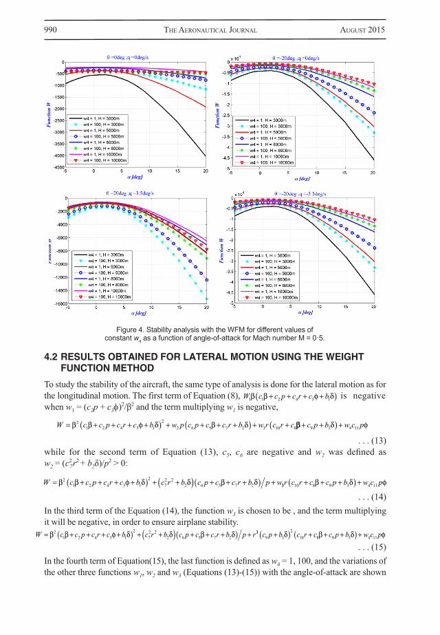
4.2 RESULTS OBTAINED FOR LATERAL MOTION USING THE WEIGHT FUNCTION METHOD
To study the stability of the aircraft, the same type of analysis is done for the lateral motion as for the longitudinal motion. The first term of Equation (8), is negative when w1 = (c2p + c3φ)2/β2 and the term multiplying w1 is negative,
. . . (13)while for the second term of Equation (13), c5, c6 are negative and w2 was defined as w2 = (c2
7 r2 + b2δ)/p2 > 0:
. . . (14)In the third term of the Equation (14), the function w3 is chosen to be , and the term multiplying it will be negative, in order to ensure airplane stability.
. . . (15)In the fourth term of Equation(15), the last function is defined as w4 = 1, 100, and the variations of the other three functions w1, w2 and w3 (Equations (13)-(15)) with the angle-of-attack are shown
Figure 4. Stability analysis with the WFM for different values of constant w4 as a function of angle-of-attack for Mach number M = 0·5.
W c c p c r c b w p c p c c r b w r c r c 21 2 4 3 1
22 6 5 7 2 3 10 8 c p b w c p9 3 4 11
W c c p c r c b1 1 2 4 3 1
W c c p c r c b c r b c p c c r b p w 21 2 4 3 1
272 2
2 6 5 7 2 33 10 8 9 3 4 11r c r c c p b w c p
W c c p c r c b c r b c p c c r b p r 21 2 4 3 1
272 2
2 6 5 7 233
9 32
10 8 9 3 4 11c p b c r c c p b w c p

BoTez & AnTon WeighT funcTions meThod for sTABiliTy AnAlysis Applied As design Tool for 991
in Fig. 5 for Mach numbers 0·4 and 0·5 and altitudes 3,000m and 8,000m. It is assumed that their variations, based on passenger comfort, are thus obtained for roll rate p = (–6 to 6)°/s, yaw rate r = (–2 to 2)°/s, sideslip angle β = (–5 to 5)° and roll angle Φ = (–15 to 15)°.
By replacing the values of w1, w2 and w3 the final form of the weight function W for lateral motion is now written in the following form:
. . . (16)
The variation of the weighting function W with the angle-of-attack α is shown for various values of w1, w2 and w3 and for combinations between the extreme values of p, r, β and φ defined in the above paragraphs.
It has been found that the Hawker 800XP aircraft has a stable lateral dynamics in climb or descent for roll, Dutch roll and spiral motions because the total weight function W variation with the angle-of-attack is negative, as seen in Figures 6 and 7 for the subsonic regime characterised by Mach numbers of 0·4 and 0·5, and four altitudes, for various combinations of p, r, β and φ.
Stability field for lateral motion are presented in Figs 6 and 7. We can seen that for M = 0·4 the instability can be encountered, if the limits of roll rate, yaw rate, sideslip angle and roll angle are increased, for high angles-of-attack in cases presented in Figures 6.(a), 6(b), 6(e), and for M = 0·5 for cases presented in Figures 7(a) and 7(e). On the other side, for small angles-of-attack, we can have stability fields if the limits presented in Figs 6(c), (d), (f), 7(c) and 7(d) are increased.
In fact, the Hawker 800XP is a stable aircraft in its longitudinal and lateral motions because the sign of the W function remains negative. In the next section, a stability analysis will be performed using the eigenvalues method, for comparison and validation purposes of the results obtained with the WFM.
(b)(a)
Figure 5. Weight functions variation with the angle-of-attack for lateral-directional motion for (a) M = 0·4 and H = 3,000m and (b) M = 0·5 and H = 8,000m.
W c p c c c p c r c b c r b c p c c r 2 32
1 2 4 3 1 72 2
2 6 5 71
bp
r c p b c r c c p b w c p
2
39 3
210 8 9 3 4 11
1

992 The AeronAuTicAl JournAl AugusT 2015
(b)
(d)
(f)
(a)
(c)
(e)
Figure 6. Lateral-directional stability analysis with the WFM for different values of constant w4 as a function of the angle-of-attack for M = 0·4.

BoTez & AnTon WeighT funcTions meThod for sTABiliTy AnAlysis Applied As design Tool for 993
(b)
(d)
(f)
(a)
(c)
(e)
Figure 7. Lateral-directional stability analysis with the WFM for different values of constant w4 as a function of the angle-of-attack for M = 0·5.

994 The AeronAuTicAl JournAl AugusT 2015
The system stability/instability can be summarised as follows:
● longitudinal motion at M = 0·5: – θ smaller than –20° with q = 0°/sec; – θ smaller than –20° and q smaller than –3·5°/sec
● lateral motion for high angles-of-attack at M = 0·4: – p smaller than –6°/s, with β = 0°, r = 0°/s and φ = 0° ; – p greater than +6°/s, with β = 0°, r = 0°/s and φ = 0° ;
● lateral motion for high angles-of-attack at M = 0·5: – p smaller than –6°/s, with β = 0°, r = 0°/s and φ = 0° ;
● lateral motion for small angles-of-attack at M = 0·4 : – r smaller than –2°/s, β smaller than –5° with p = 0°/s and φ = 0° ; – r greater than –2°/s, β greater than –5° with p = 0°/s and φ = 0°;
● lateral motion for small angles-of-attack at M = 0·5: – r smaller than –2°/s, β smaller than –5° with p = 0°/s and φ = 0° ; – r greater than +2°/s, β greater than –5° with p = 0°/s and φ = 0°.
5.0 EIGENVALUES STABILITY ANALYSS OF THE LINEAR
SMALL-PERTURBATION EQUATIONSThe eigenvalues stability analysis was used to validate the results obtained with the Weight Function Method, based on the aerodynamics coefficients and their derivatives obtained with FDerivatives code. Five dynamic modes of motion describe the aircraft’s response to an initial condition of any origin (turbulence, control input, etc.). These five modes are: the short period and the long period for the longitudinal aircraft motion, and the roll, Dutch roll and spiral for the lateral motion. These modes are separated as they are defined by the equations described in sections V.1 and V.2 for longitudinal and lateral motions, respectively. Their estimation is made in open-loop.
5.1 LONGITUDINAL MOTION RESULTS
The longitudinal motion can be divided into two motions: short period and phugoid. The short period pitch response is the short term response (from 1 sec to 4 sec) of a longitudinal motion to a disturbance. The main variables are the angle-of-attack α, the load factor n and the pitch angle θ. It is interesting to find the relationship between the damping ratio of the short period oscillation (ζsp), the un-damped natural frequency of the short period oscillation (ωsp), and the change in normal acceleration per unit change in angle-of-attack for an incremental pitch control deflection at constant airspeeds and Mach numbers.
The mathematical model(19) which describes this longitudinal motion can be represented in the form of the state space first equation (Equation(2)):

BoTez & AnTon WeighT funcTions meThod for sTABiliTy AnAlysis Applied As design Tool for 995
. . . (17)
For both longitudinal modes, the natural frequency ωn and damping ratio are estimated from the characteristic equation as function of the eigenvalues λ1, λ2, λ3 and λ4 (Equation (18)), with the mention that λ1,2 are the eigenvalues corresponding to short-period and λ3,4 to phugoid motions.
. . . (18)
The natural frequencies ωn and the damping ξ of short-period and phugoid modes verify the next Equation (19).
. . . (19)
The imaginary parts of eigenvalues are presented as function of their real parts in Fig. 8 where it can be observed that all the real parts of the eigenvalues are negative, which means that, in terms of stability, the aircraft longitudinal mode is stable in both short-period and phugoid modes. For phugoid mode real parts of eigenvalues are negatives, but they are very closed to positive values if the limits are increased, that means pitch angles θ greater than 20° or smaller than –20° and pitch rates q smaller than –3·5°/s or greater than 3·5°/s.
A
X XV
gV
VZV Z
ZV Z
V ZV Z
VM VZ MV Z
M
long
u
u q
uu
0
0
ZZ MV Z
M MV ZV Z
x
lon
0
0 0 1 0
, gg long
u
qB
XVZ
V Z
M Z MV Z
,
0
,ulong �
n
n
n
n
Re
Im,
Re
Im
,
,
,
,
1 2
21 2
3 4
23 41 1
I Along 0
p p np np sp sp nsp nsp2 2 2 22 2 0
Figure 8. Root locus plot (Imaginary vs Real eigenvalues) longitudinal motion representation for M = 0·4 and 0·5.

996 The AeronAuTicAl JournAl AugusT 2015
5.2 LATERAL MOTION RESULTS
Based on Equations (1) and (2) the system can be written in the following form(19):
. . . (20)
Generally, the eigenvalues λ1, λ2, λ3 and λ4 of the characteristic equation for the lateral motion are composed of two real eigenvalues and a pair of complex eigenvalues. The eigenvalues are chosen so that the response of the aircraft is characterised by the following modes (23):● A Spiral mode characterised by convergent or divergent motions;
● A Roll mode characterised by fast convergent motion; and
● A Dutch Roll mode characterised by lightly damped oscillatory motion with a low frequency.
The rolling motion is generally quite damped and is reaching the steady state in a very short time. In the case of a roll mode, the desired roll rates and angles can be obtained. The rapidity with which the commanded roll rate is reached influences the response to the inputs and also the ability to achieve and maintain the roll angle φ.
Dutch roll motion is a combination of yaw and roll motions, and is the lateral-directional short period oscillatory mode. The Dutch roll is a nuisance mode that appears in the roll response to lateral control and can introduce non-controlled and non-desired roll and yaw motion. These motions can significantly influence the ability of the pilot to precisely control lateral-directional motions. Figure 9 shows the eigenvalues (imaginary versus real parts) variations for the lateral aircraft analysis. It can be concluded that the Hawker 800XP is a stable aircraft in its lateral motion for all three motions (roll, spiral and Dutch roll).
Figure 9. Root locus plot (Imaginary vs Real eigenvalues) lateral directional motion representation for M = 0·4 and 0·5.
A
YV
YV
Y VV
gu
L N II
G L N IIlat
p r
xz
xp p
xz
x
G
0
0Cos
GG L N II
N L II
G N L II
G N L
r rxz
x
xz
zp p
xz
zrG
0
rrxz
z
lat
II
xpr
0
0 1 0 0
,
,�
YV
G L N II
G N L II
lat
xz
x
xz
z
�
� �
� �
0
,ulat a
I Along 0
δB

BoTez & AnTon WeighT funcTions meThod for sTABiliTy AnAlysis Applied As design Tool for 997
We can see that for highest altitude the stability field is close to become unstable, roots can develop negative real parts, meaning that any changed of limits defined as roll rate p = (–6 to 6)°/s, yaw rate r = (–2 to 2)°/s, sideslip angle β = (–5 to 5)° and roll angle Φ = (–15 to 15)° could induced instability.
6.0 CONCLUSIONSThe main aim was to determine, as a design tool, the positive weight functions by the Weight Function Method in order to analyse the stability fields of a Hawker 800XP configuration. The eigenvalue stability analysis of the linear small-perturbation equations was chosen for validation, because the eigenvalues can be rapidly determined for any flight condition or from the stability derivatives for one particular flight case. The aerodynamic coefficients and their stability derivatives were found with our new in-house FDerivatives code.
Based on the aircraft’s aerodynamic model calculated with the WFM, three functions were defined in terms of stability derivatives terms, and the last function was considered positive and chosen to be 1 and 100. The WFM was applied for longitudinal and lateral motion studies.
For all four altitudes considered at two Mach numbers, the longitudinal dynamics of the Hawker 800XP remains stable for any combination of pitch angle θ and pitch rate q. It has been found that the Hawker 800XP aircraft has stable lateral dynamic stability in climb or descent for roll, Dutch roll and spiral motions because the total weight function W variation with the angle-of-attack is negative for the subsonic regime characterised by Mach numbers of 0·4 and 0·5, and four altitudes, for combinations of p, r, β and φ.
ACKNOWLEDGEMENTSWe would like to thank CAE Inc. team for the Hawker 800XP aircraft data required to obtain the results presented in this paper.
REFERENCES1. yoichi, S. and yAsumi, K. Numerical weight function method for structural analysis formulation for two–
dimensional elasticity and plate structures, J Soc of Naval Architects of Japan, 2003, ISSN 0514–8499, 193, pp 33–38.
2. Kim, J.H. and lee, S.B. Calculation of stress intensity factor using weight function method for a patched crack with debonding region, Engineering Fracture Mechanics, 2000, 67, pp 303–310.
3. pAris, P.C., mcmeeKing, R.M. and TAdA, H. The Weight Function Method for Determining Stress Intensity factors, Cracks and Fracture – Proceedings of the Ninth national Symposium on Fracture Mechanics, 1976, 76, (1712), pp 471–489.
4. Wu, X.R. and cArlsson, J. The generalised weight function method for crack problems with mixed boundary conditions, J Mechanics and Physics of solids, 1983, 31, (6), pp 485–497.
5. feTT, T. An analysis of the three-point bending bar by use of the weight function method, Engineering Fracture Mechanics, 1991, 40, (3), pp 683-686.
6. schneider, G.A. and dAnzer, R. Calculation of stress intensity factor of an edge crack in a finite elastic disc using the weight function method, Engineering Fracture Mechanics, 1989, 34, (3), pp 547-552.
7. sTroe, I. Weight Functions Method in stability study of vibrations, SISOM 2008 and Session of the Commission of Acoustics, Bucharest, Hungary, 29-30 May 2008.
8. sTroe, I. and pArVu, P. Weight Functions Method in Stability Study of Systems, PAMM, Proc. Appl. Math. Mech. 8, 10385 – 10386 (2008) / DOI 10.1002/pamm.200810385.

998 The AeronAuTicAl JournAl AugusT 2015
9. JiAnKun, h., Bohn, c. and Wu, h.r. Systematic H∞ weighting function selection and its application to the real–time control of a vertical take-off aircraft, Control Engineering Practice, 2000, 8, pp 241–252.
10. AnTon, N. Analiza miscarii longitudinale a unui avion de mare manevrabilitate prin metoda bifurcatiei, “AEROSPACE 2005” Conference, Bucharest, Hungary, 11-12 October, 2005.
11. Wilde, J. Linear Algebra II: Quadratic Forms and Definiteness, 26 August 2011. http://www.econ.brown.edu/students/Takeshi_Suzuki/Math_Camp_2011/LA2-2011.pdf
12. schmidT, L.V. Introduction to Aircraft Flight Dynamics, AIAA Education Series, 1998.13. AnTon, n., BoTez, r.m. and popescu, d. New methodology and code for Hawker 800XP aircraft stability
derivatives calculation from geometrical data, Aeronaut J, 2010, 114, (1156).14. AnTon, N., BoTez, R.M. and popescu, D. New methods and code for aircraft stability derivatives
calculations from its geometrical data, AIAA Atmospheric Flight Mechanics Conference, Chicago, IL, USA, 10-13 August 2009.
15. AnTon, n., BoTez, R.M. and popescu, D. Stability derivatives for X-31 delta-wing aircraft validated using wind tunnel test data, Proceeding of the Institution of Mechanical Engineering, Part G, J Aero Eng, April 2011, pp 403-416.
16. AnTon, N. and BoTez, R.M. A new type of the stability derivatives for X-31 model aircraft validated using wind tunnel test data, Applied Vehicle Technology Panel Specialists Meeting AVT-189, Assessment of Stability and Control Prediction Methods for NATO Air and Sea Vehicles, Dstl Portsdown West, Fareham, Hampshire, Grande Bretagne, UK, 12-14 October, 2011
17. AnTon, N. and BoTez, R.M. Weight Functions Method Application on a Delta-Wing X-31 configurations, INCAS Bulletin, 2011, 3, (4), pp 3-16, ISSN 2066-8201.
18. AnTon, N., BoTez, R.M. and popescu, D. Application of the weight function method on a high incidence research aircraft model, Aeronaut J, 2013, 117, (1195), pp 1-16.
19. eTKin, B., and reid, L. Dynamics of Flight: Stability and Control, J. Wiley & Sons, 1996. 20. hAmel, c., sAssi, A., BoTez, r. and dArTigues, c. Cessna Citation X aircraft global model identification
from fight tests, SAE Int J Aerospace, 2013, 6, (1), pp 106-114, doi:10.4271/2013-01-2094.21. Boely, N. and BoTez, R.M. New approach for the identification and validation of a nonlinear F/A-18
model by use of neural networks, IEEE Transactions on Neural Networks, 2010, 21, (11), pp 1759-1765.22. KouBA, g., BoTez, r.m. and Boely, n. Fuzzy logic method use in the F/A-18 aircraft model identifi-
cation, sous presse, AIAA J Aircr, 2009, 47, (1), pp. 1-1723. hodgKinson, J. Aircraft Handling Qualities, AIAA Education Series, 1999.