week 9 - project 1 - adding loads and constraints
DESCRIPTION
Week 9 - Project 1 - Adding Loads and ConstraintsTRANSCRIPT
ME 24-688 – Week 9
Adding Loads and Constraints
ME 24-688 – Introduction to CAD/CAE Tools Page 1 of 15
Adding Loads and Constraints
During these projects you will create different loads and constraint and explorer the general interface of
the linear FEA capabilities available within Autodesk Inventor Professional 2014.
1.1 Project 1A – Create Loads and Constraints
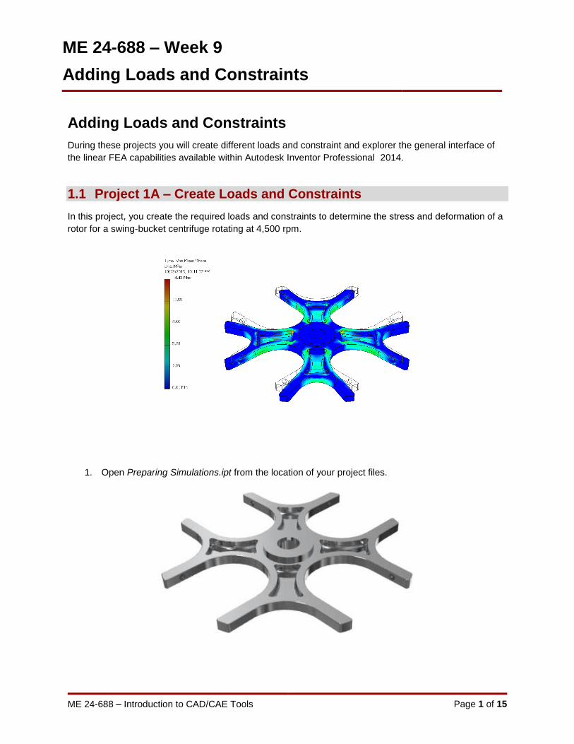
In this project, you create the required loads and constraints to determine the stress and deformation of a
rotor for a swing-bucket centrifuge rotating at 4,500 rpm.
1. Open Preparing Simulations.ipt from the location of your project files.

ME 24-688 – Week 9
Adding Loads and Constraints
ME 24-688 – Introduction to CAD/CAE Tools Page 2 of 15
2. Enter the Stress Analysis environment by picking Environments | Begin | Stress Analysis
from the Ribbon.
3. On the Manage panel, click Create Simulation.
4. In the Create New Simulation dialog, enter Body Loads for the Name.
5. In the Create New Simulation dialog, select the Detect and Eliminate Rigid Body Modes
check box to turn it on. This setting will use an algorithm to stop movement in the part if there are
not enough constraints to fix it based off the center of mass of the component. This is needed
because of the pin constraint added later is the only constraint leaving one degree of freedom.
6. Click OK to dismiss the Create New Simulation dialog.
7. In the Browser, expand Preparing Simulations part so that you can see all of the individual
features.

ME 24-688 – Week 9
Adding Loads and Constraints
ME 24-688 – Introduction to CAD/CAE Tools Page 3 of 15
8. Right-click on Fillet2 and pick Exclude From Simulation on the Browser menu
The Browser will update and the glyph will change to indicate that the feature is no longer
part of the simulation.
9. Pick the Assign button from the Material panel of the Ribbon.
10. In the Assign Materials dialog, Select Aluminum 6061 in the Override Material column.
Next, pick OK to dismiss the Assign Materials dialog.
11. Expand the Material node in the Browser. Then expand the Aluminum-6061 node. Notice the
Browser displays the material override.
ME 24-688 – Week 9
Adding Loads and Constraints
ME 24-688 – Introduction to CAD/CAE Tools Page 4 of 15
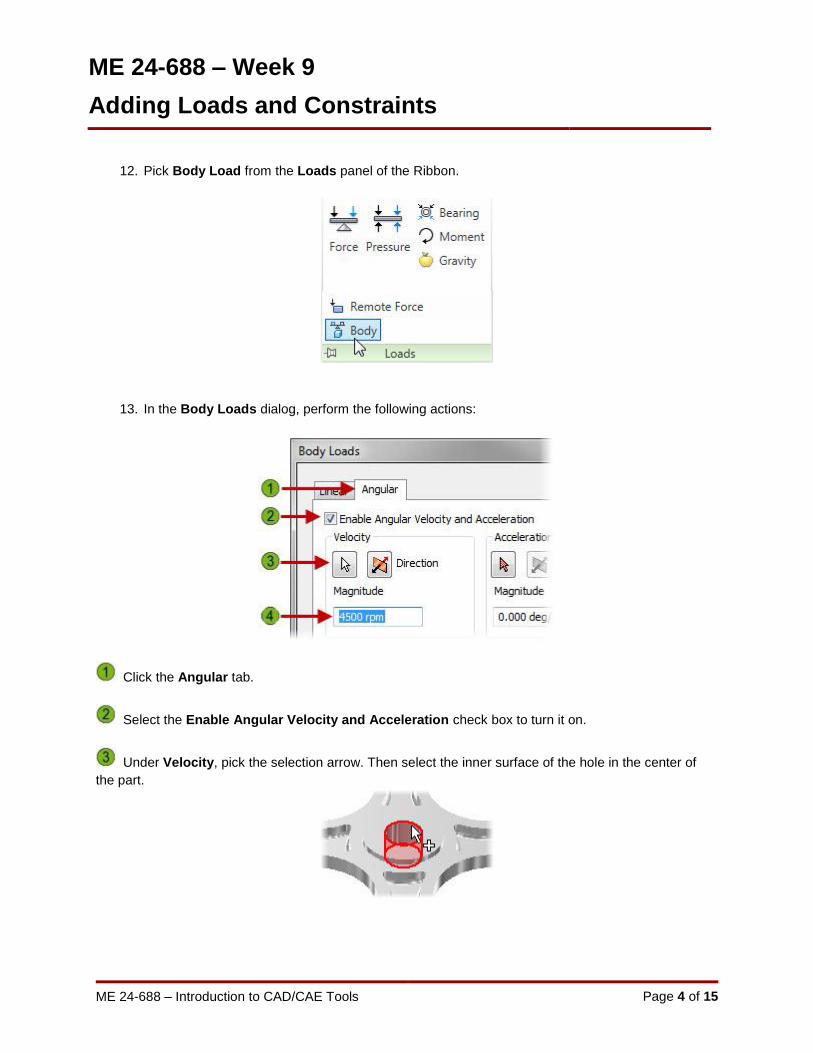
12. Pick Body Load from the Loads panel of the Ribbon.
13. In the Body Loads dialog, perform the following actions:
Click the Angular tab.
Select the Enable Angular Velocity and Acceleration check box to turn it on.
Under Velocity, pick the selection arrow. Then select the inner surface of the hole in the center of
the part.

ME 24-688 – Week 9
Adding Loads and Constraints
ME 24-688 – Introduction to CAD/CAE Tools Page 5 of 15
Enter 4,500 rpm for the Magnitude. Your model should now resemble the figure below.
Click OK to dismiss the Body Loads dialog.
14. On the Constraints panel, click Pin.
Select the inner cylindrical surface of the hole in the center of the hub.
Click OK to dismiss the Pin Constraint dialog.
15. Start the Simulate dialog by choosing Solve from the Simulate Ribbon or Simulate from the
Marking Menu. Pick Run to continue.

ME 24-688 – Week 9
Adding Loads and Constraints
ME 24-688 – Introduction to CAD/CAE Tools Page 6 of 15
16. When the analysis is complete, the Von Mises Stress is displayed on the displaced model. The
stress is far below the yield strength of the material.
17. Pick Prepare | Mesh View from the Ribbon or Mesh View from the Marking Menu.
The mesh is displayed.
Click Mesh View again to turn off the mesh.

ME 24-688 – Week 9
Adding Loads and Constraints
ME 24-688 – Introduction to CAD/CAE Tools Page 7 of 15
18. To ensure the results are valid and there are no stress singularities display the convergence plot
by clicking Result panel | Convergence. This will show how the solution was solved three times
and they converged within 16 %. Autodesk Inventor Professional automatically runs three
refinements for parts and two for assemblies known as “P” refinement.
19. You now promote the material to the part so that the material is set in the part environment.
Right-click Preparing Simulations under the Material | Aluminum-6061 node in the Browser
and choose pick Promote Materials to Model from the Browser Menu.

ME 24-688 – Week 9
Adding Loads and Constraints
ME 24-688 – Introduction to CAD/CAE Tools Page 8 of 15
Notice the change in the Browser, in which the folders below the Material folder are removed
because there are no longer material overrides in the Stress Analysis environment.
20. Leave the Stress Analysis environment by picking Exit | Finish Stress Analysis from the
Ribbon.
21. Close all files without saving.

ME 24-688 – Week 9
Adding Loads and Constraints
ME 24-688 – Introduction to CAD/CAE Tools Page 9 of 15
1.2 Project 1B – Simulate Loads Project
In this project you add forces to a part that simulate the loads and constraints imposed by other
components in an assembly. The magnitude of the forces was calculated based on the rotational velocity,
mass of the other components, and swing radius.
1. Open Preparing Simulations - Swing Buckets.ipt from the location of your project files.

ME 24-688 – Week 9
Adding Loads and Constraints
ME 24-688 – Introduction to CAD/CAE Tools Page 10 of 15
2. Enter the Stress Analysis environment by picking Environments | Begin | Stress Analysis
from the Ribbon.
3. Right-click over the Body Loads node and choose Copy Simulation from the Browser menu.
4. Right-click over the new simulation, Body Loads:1, node and pick Edit Simulation Properties
from the Browser menu.
5. In the Simulation Properties dialog, enter Body and Force Loads in the Name field. Click OK
to dismiss the dialog.

ME 24-688 – Week 9
Adding Loads and Constraints
ME 24-688 – Introduction to CAD/CAE Tools Page 11 of 15
6. Start the Bearing Load dialog by choosing Loads | Bearing from the Ribbon.
7. Starting with the cutout that is aligned with the positive X axis, select the two holes on either side
of the cutout.
8. Pick the Direction button from the Bearing Load dialog. Select an edge that is aligned with the
positive X axis so that the forces point in the positive X direction, outward from the center of the
model. Use the Flip Direction button if necessary.
9. Enter 1600N for the Magnitude and click Apply, but do not dismiss the Bearing Load dialog.

ME 24-688 – Week 9
Adding Loads and Constraints
ME 24-688 – Introduction to CAD/CAE Tools Page 12 of 15
10. Repeat the Bearing Load application steps for the other three cutouts, ensuring that the loads
point out from the center of the part, as shown below.
Dismiss the Bearing Load dialog when all four pairs of loads have been applied.
11. Start the Simulate dialog by choosing Solve | Simulate from the Ribbon or Simulate from the
Marking Menu. Pick Run to continue.
The Von Mises Stress is displayed, as shown below.

ME 24-688 – Week 9
Adding Loads and Constraints
ME 24-688 – Introduction to CAD/CAE Tools Page 13 of 15
12. We will now change the magnitude of the loads. If you have multiple load values to change, it is
often easier to modify the values in the Parameters dialog box rather than editing each load from
the Stress Analysis browser.
Click Manage | Parameters | Parameters from the Ribbon.
13. When the Parameters dialog appears scroll down until the Body and Force Loads section is
displayed.
14. Change the four 1600N entries to 2000N.
Click Done to confirm the changes and dismiss the Parameters dialog.
15. Click the Stress Analysis tab from the Ribbon. Notice that the Browser now indicates that the
results are out of date with red lightning bolt glyphs.

ME 24-688 – Week 9
Adding Loads and Constraints
ME 24-688 – Introduction to CAD/CAE Tools Page 14 of 15
16. Expand the Loads node of the Browser and double-click any one of the bearing loads. Confirm
that the Magnitude is now 2000N, and then click OK to dismiss the dialog.
17. Again start the Simulate dialog by choosing Solve | Simulate from the Ribbon or Simulate from
the Marking Menu. Pick Run to continue.
The updated Von Mises Stress is displayed for the 2000N loads.

ME 24-688 – Week 9
Adding Loads and Constraints
ME 24-688 – Introduction to CAD/CAE Tools Page 15 of 15
18. Review the convergence plot by clicking Result panel | Convergence to ensure the results are
valid. You will see the convergence rate is 4% so they are within the 10% default limit.
19. Leave the Stress Analysis environment by picking Exit | Finish Stress Analysis from the
Ribbon.
20. Close all files without saving.