wedell williams racer - aerodromerc.com · wedell williams 52.4” page 5 copyright© 2005‐11...
TRANSCRIPT
Wedell Williams 52.4”
Copyright© 2005‐11 M.K. Bengtson All Rights Reserved Rev 07/11
Wedell Williams Racer
R/C Scale Model Instructions
CONTACT INFORMATION
Designed by M.K. Bengtson
Prototype by Greg Smith
Manufactured and Distributed by:
Bengtson Company
e‐mail: [email protected]
Web Site: www.aerodromerc.com

Wedell Williams 52.4” Page 2
Copyright© 2005‐11 M.K. Bengtson All Rights Reserved Rev 07/11
WEDELL WILLIAMS Thank you for purchasing the Wedell Williams model for electric flight.
THE MODEL
A semi 1/6th scale adaptation of the Wedell Williams, this model is designed to be easy to build and exciting to fly.
Finished Model by Greg Smith
POWER SET UP The AXI 2820/12 Direct Drive motor and a 12/8 APC prop power the model. Battery power pack is a 3100 mah 3s2p lithium pack.
SPECIFICATIONS More than 205 laser cut parts
Scale: 1/6 Channels: R/E/A/T Wingspan: 52.4” Wing Area: 441 sq in Weight: 52 oz Power System: AXI 2826/12 Direct Drive Prop: 12x8 APC Wheels: Balsa & plywood, Neoprene foam tires Airfoil Type: Flat bottomed Cowl: Tapered, Built up balsa and plywood Spinner: N/A Dummy Motor: Balsa and plywood
Kit Includes Vacuum Formed Canopy
Replacement Engine Fronts and Canopies Available at: www.AerodromeRC.com
BUILDING THE MODEL Before Starting A note about the photos: The photos were taken of a prototype and the parts supplied may look slightly different from them. However, the concepts illustrated are the same.
WINGS The wing is built in three pieces, two outer panels and a center section. Build the sections and join them later. Start by building the center section. The spars are 1/4ʺ balsa. For the center section, everything pins to the board. Add the plywood landing gear mounts. Insert the blind nuts and glue in place. Add the leading edge stock after the basic frame is done as the stock is inserted in a rotated fashion.
Wing Center Section
For the outer panels, the center most rib is angled to allow for dihedral, and the kit includes a template to set the dihedral angle. Once the leading edge is on, shim up the entire wing panel off the building board with scrap 1/8ʺ balsa and re‐pin the panel (that now has a leading edge) to the board. This shimming is necessary so the leading edge clears the board, allowing the whole wing panel to be pinned down again.
Wing Construction Detail
Wedell Williams 52.4” Page 3
Copyright© 2005‐11 M.K. Bengtson All Rights Reserved Rev 07/11
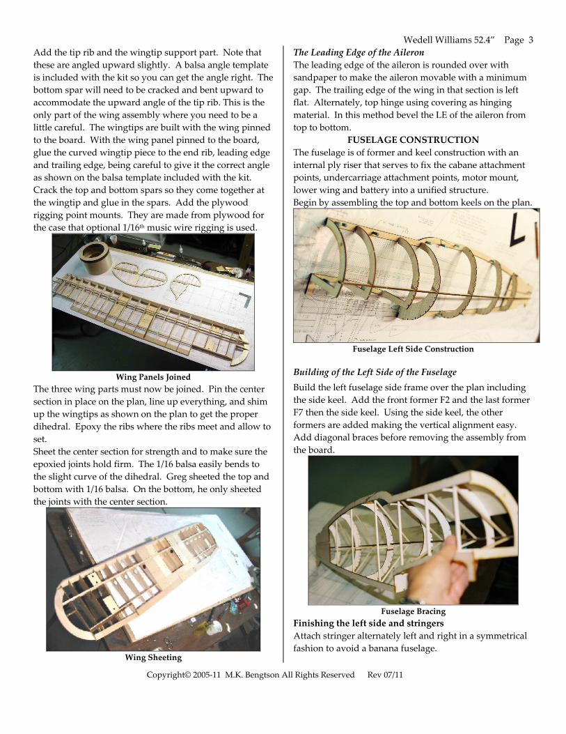
Add the tip rib and the wingtip support part. Note that these are angled upward slightly. A balsa angle template is included with the kit so you can get the angle right. The bottom spar will need to be cracked and bent upward to accommodate the upward angle of the tip rib. This is the only part of the wing assembly where you need to be a little careful. The wingtips are built with the wing pinned to the board. With the wing panel pinned to the board, glue the curved wingtip piece to the end rib, leading edge and trailing edge, being careful to give it the correct angle as shown on the balsa template included with the kit. Crack the top and bottom spars so they come together at the wingtip and glue in the spars. Add the plywood rigging point mounts. They are made from plywood for the case that optional 1/16th music wire rigging is used.
Wing Panels Joined
The three wing parts must now be joined. Pin the center section in place on the plan, line up everything, and shim up the wingtips as shown on the plan to get the proper dihedral. Epoxy the ribs where the ribs meet and allow to set. Sheet the center section for strength and to make sure the epoxied joints hold firm. The 1/16 balsa easily bends to the slight curve of the dihedral. Greg sheeted the top and bottom with 1/16 balsa. On the bottom, he only sheeted the joints with the center section.
Wing Sheeting
The Leading Edge of the Aileron The leading edge of the aileron is rounded over with sandpaper to make the aileron movable with a minimum gap. The trailing edge of the wing in that section is left flat. Alternately, top hinge using covering as hinging material. In this method bevel the LE of the aileron from top to bottom.
FUSELAGE CONSTRUCTION The fuselage is of former and keel construction with an internal ply riser that serves to fix the cabane attachment points, undercarriage attachment points, motor mount, lower wing and battery into a unified structure. Begin by assembling the top and bottom keels on the plan.
Fuselage Left Side Construction
Building of the Left Side of the Fuselage Build the left fuselage side frame over the plan including the side keel. Add the front former F2 and the last former F7 then the side keel. Using the side keel, the other formers are added making the vertical alignment easy. Add diagonal braces before removing the assembly from the board.
Fuselage Bracing
Finishing the left side and stringers Attach stringer alternately left and right in a symmetrical fashion to avoid a banana fuselage.

Wedell Williams 52.4” Page 4
Copyright© 2005‐11 M.K. Bengtson All Rights Reserved Rev 07/11
Fuselage Right Side Formers in Place
Fuselage Sheeted and Stringered
1/16th balsa sheeting is shown. Choose the lightest balsa. The motor mount is designed for an AXI 2820/12. It is easy to assemble, with down and right thrust incorporated into the parts.
Fuselage Motor Mount
TAIL SURFACES
Lay out and glue parts of the tail surfaces on the plans. Sand the tail parts, rounding off all edges. Don’t add the horns or hinge the surfaces until after covering is complete.
Vertical Tail Surface Construction
Horizontal Tail Surface Construction l
LANDING GEAR The landing gear is made from 1/8” music wire.
Adding the Undercarriage mounts The undercarriage is mounted using 1/8” landing gear straps.
Wing Fairings Greg fashioned wooden wing fairings. He says: ”The base for the fillets is 1/32 ply. To make it bend around the forward edge of the wing, cut kerfs. Donʹt worry if you cut through the thin ply, you can just tape the little kerf pieces on then glue them to the frame. “
Wing Fairing 1/32” Ply Scoring
Wedell Williams 52.4” Page 5
Copyright© 2005‐11 M.K. Bengtson All Rights Reserved Rev 07/11
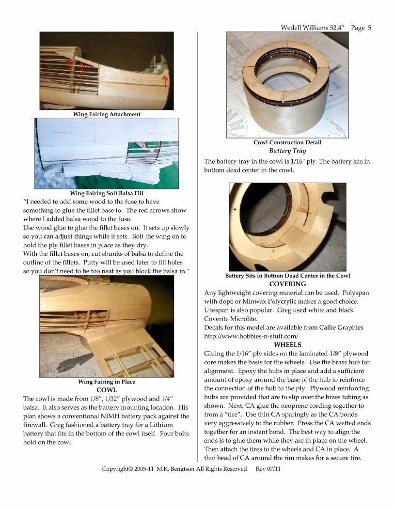
Wing Fairing Attachment
Wing Fairing Soft Balsa Fill
“I needed to add some wood to the fuse to have something to glue the fillet base to. The red arrows show where I added balsa wood to the fuse. Use wood glue to glue the fillet bases on. It sets up slowly so you can adjust things while it sets. Bolt the wing on to hold the ply fillet bases in place as they dry. With the fillet bases on, cut chunks of balsa to define the outline of the fillets. Putty will be used later to fill holes so you donʹt need to be too neat as you block the balsa in.“
Wing Fairing in Place
COWL The cowl is made from 1/8”, 1/32” plywood and 1/4” balsa. It also serves as the battery mounting location. His plan shows a conventional NIMH battery pack against the firewall. Greg fashioned a battery tray for a Lithium battery that fits in the bottom of the cowl itself. Four bolts hold on the cowl.
Cowl Construction Detail
Battery Tray The battery tray in the cowl is 1/16ʺ ply. The battery sits in bottom dead center in the cowl.
Battery Sits in Bottom Dead Center in the Cowl
COVERING Any lightweight covering material can be used. Polyspan with dope or Minwax Polycrylic makes a good choice. Litespan is also popular. Greg used white and black Coverite Microlite. Decals for this model are available from Callie Graphics http://www.hobbies‐n‐stuff.com/
WHEELS Gluing the 1/16” ply sides on the laminated 1/8” plywood core makes the basis for the wheels. Use the brass hub for alignment. Epoxy the hubs in place and add a sufficient amount of epoxy around the base of the hub to reinforce the connection of the hub to the ply. Plywood reinforcing hubs are provided that are to slip over the brass tubing as shown. Next, CA glue the neoprene cording together to from a “tire”. Use thin CA sparingly as the CA bonds very aggressively to the rubber. Press the CA wetted ends together for an instant bond. The best way to align the ends is to glue them while they are in place on the wheel. Then attach the tires to the wheels and CA in place. A thin bead of CA around the rim makes for a secure tire.
Wedell Williams 52.4” Page 6
Copyright© 2005‐11 M.K. Bengtson All Rights Reserved Rev 07/11
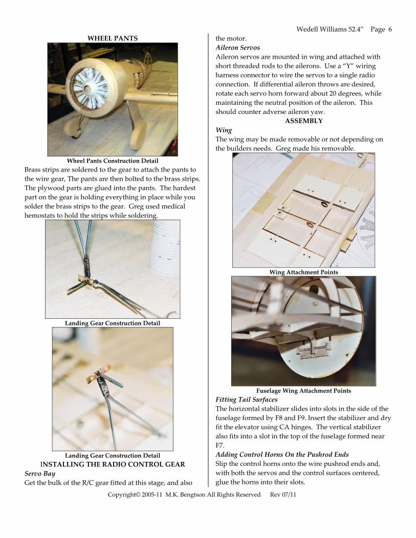
WHEEL PANTS
Wheel Pants Construction Detail
Brass strips are soldered to the gear to attach the pants to the wire gear, The pants are then bolted to the brass strips. The plywood parts are glued into the pants. The hardest part on the gear is holding everything in place while you solder the brass strips to the gear. Greg used medical hemostats to hold the strips while soldering.
Landing Gear Construction Detail
Landing Gear Construction Detail
INSTALLING THE RADIO CONTROL GEAR Servo Bay Get the bulk of the R/C gear fitted at this stage, and also
the motor. Aileron Servos Aileron servos are mounted in wing and attached with short threaded rods to the ailerons. Use a “Y” wiring harness connector to wire the servos to a single radio connection. If differential aileron throws are desired, rotate each servo horn forward about 20 degrees, while maintaining the neutral position of the aileron. This should counter adverse aileron yaw.
ASSEMBLY Wing The wing may be made removable or not depending on the builders needs. Greg made his removable.
Wing Attachment Points
Fuselage Wing Attachment Points
Fitting Tail Surfaces The horizontal stabilizer slides into slots in the side of the fuselage formed by F8 and F9. Insert the stabilizer and dry fit the elevator using CA hinges. The vertical stabilizer also fits into a slot in the top of the fuselage formed near F7. Adding Control Horns On the Pushrod Ends Slip the control horns onto the wire pushrod ends and, with both the servos and the control surfaces centered, glue the horns into their slots.

Wedell Williams 52.4” Page 7
Copyright© 2005‐11 M.K. Bengtson All Rights Reserved Rev 07/11
Fitting the Rigging Wires Use strong thread or Kevlar fishing line or elastic beading cording to simulate rigging wires. Use small screws, fishing hook eyes, straight pinheads or small eyelets to attach the lines. These “wires” can add a degree of strength to your model. Greg made his rigging removable: ”The flying wires are thick elastic thread from a craft store. I sink one magnet in the model, with its top even with the model skin, and hold it with a drop of CA. I then take another magnet, and CA the end of the thread to it. I paint the top magnet so that it blends with the fuse. This makes the attachment point almost disappear, an optical illusion. I paint the thread after it is on the model with silver acrylic paint.”
Balancing the Model Balance the model at the point shown.
FLYING The model should ROG on grass, pavement or hard surfaces. It may require coordinated turns using both ailerons and rudder control. This is due to adverse yaw. Halving the aileron down throw may reduce the effect. This can be accomplished by rotating the control arm of the aileron servo forward about 20 degrees.
In for a Landing
The tail surfaces should not need excessive throws. Let the model gain altitude slowly off the runway. Applying too much up elevator at slow speeds risks a stall. Make your turns gently as tight turns risk tip stalling in any model. Don’t expect the elevator to make the model climb. Think of the elevator as a device to change the attitude of the model. The wing and airspeed ultimately make the model climb. Often down elevator applied at stalling can avoid a major crash. The most important details for proper flight operations are: 1. CG location. Tail heavy models never fly well or at all. 2. Down and right thrust 3. Straight and non warped wings.
Here are some excerpts of Gregʹs maiden flights. “First attempt with an 11x7 Master Airscrew wood electric prop and a 3100 mah 3s2p lithium pack showed not enough power, so I changed to a 12x8 APC. AUW was about 52 oz. This combination provided massive power, model is airborne in about 30 feet. The big cowl creates significant wind shadow, so a fair amount of right rudder was required to keep it tracking straight on take‐off roll. With the drag of the big cowl, coupled with the light design and good wing area, the model flies well and briskly, although not really fast. I wouldnʹt call it a ʺslow flyerʺ but itʹs not quite a fast sport plane, although its speed is definitely faster than scale when you push it. Full power produces a rapid climb vs. more speed. In the future I will consider mixing in some down elevator with throttle on my computer radio. It slows way down for landing, or cruising if you prefer. Most of the flight was at ½ throttle. The landing roll out was about 20 feet in a light breeze landing into the wind. Loops are easy and tight, rolls pretty and are at a modest rate. The original was not intended to roll, so the scale‐size ailerons limit the model’s roll rate compared to most sport models that can roll like crazy. Adverse yaw, typical on models like this, was noticeable although not a problem. Builders with computer radios may want to consider mixing rudder to ailerons and incorporating differential by operating the ailerons off two channels. Throws of +/‐ 1ʺR, 1‐1/8ʺ E, 1‐3/16ʺ seemed to work well. As long as you are ready for it and stand on rudder, you can take track straight on take‐off. All in all, a model with very good flight characteristics and a unique profile and a happy builder.“
CONTACT INFORMATION Distributed by:
Bengtson Company e‐mail: [email protected]
Web Site: www.aerodromerc.com