downloads.spj.sciencemag.orgdownloads.spj.sciencemag.org/research/2019/3838603.f1.docx · web...
TRANSCRIPT

1 Residential apartment
The system electricity demand comes from a residential apartment which is located on the
second floor of GEL, Figure S1. It is a fully functional flat with a living room, a kitchen, a small
study room, a double bedroom and a bathroom.
Figure S1: Residential apartment on the second floor of the Green Energy Laboratory
The apartment has an area of 60 m2, a length of 9 m, a width of 6.6 m and a height of 3 m.
The south facade, west facade and north facade are external walls. East facade and ground are
adjacent to other laboratories. The data of the building and the thermal model built using it are
taken from the previous study (Bo, W., Jingyi, W., & Ruzhu, W. (2013). Performance Analysis of
Energy-efficient Apartment in Hot Summer and Cold Winter Zone (in Chinese). Electricity and
Energy (Vol. 34, No. 2), 124-127.) on this apartment on building energy efficiency. The apartment
is equipped with energy efficient home appliances, such as induction cooker, refrigerator, washing
machine, dishwasher and energy saving lighting. An air-sourced heat pump is used for both air
conditioning operations of winter heating and summer cooling. A list of the electrical demand
items is provided by Table S1.
Table S1: List of the electrical demand items

List of electrical demand items Nominal electrical power
Air Sourced Heat Pump for Air Conditioning 3.23/3.58 kW (heating/cooling)
Induction cooker 2.6 kW
Range hood 180 W
Refrigerator 0.65kWh/24 hours
TV(2 sets) 275 & 300 W
Other cooking appliances 1.2 kW
Lighting 800W
The air-source heat pump is composed by one external unit and two internal units. The
outdoor unit is single phase/220 V/50 Hz machine. The thermal heating and cooling rates are 11.2
kW and 10kW respectively, while the rated electrical input is 3.23 kW and 3.58kW giving an
average COP of 3.47 for heating and 2.79 for cooling. It has a variable speed motor to modulate
the output, rather than having an ON/OFF control strategy. After the air-conditioning, the second
most demanding electrical equipment is the induction cooker. It will be shown later how it affects
the electricity demand especially in terms of power.
The house is designed to be all-electric, without gas burning equipment. Hot water in fact is
produced by another dedicated air source heat pump water heater with 150 Litre water tank. This
facility however was not available during our experiments, hence was excluded by our scope.
Another unavailable equipment was the Heat Recovery Ventilation (HRV) unit, therefore fresh air
was assumed to be directly infiltrating from the outside (0.5 house volume per hour is assumed in
the computational model), with loss of energy saving potential.
2 PV generation system
The PV system is conveniently located on top of the roof of the glass conservatory on the
south-facing side of the apartment (Figure S2). It is composed by 30 mono-crystalline silicon PV
panels, each of them has 100 W of rated peak power, totaling 3 kW peak. The panels are arranged
on top of the 20 degree inclined roof, divided into 2 strings of 15 panels in series one facing west,
the other facing east. The module parameters are shown in Table S2.
Figure S2: PV generation plant
Table S2: PV module parameters
Parameters Values
Peak power (Pmax) 100 W
Peak voltage (Vmp) 18V
Open circuit voltage (Voc) 21.6 V
Peak current (Imp) 5.55 A
Short circuit current (Isc) 6.06 A
Solar panel working temperature range -40/85 oC

3 Battery Energy Storage System
The advanced lead-acid batteries are AGM (absorbent glass mat) VRLA (valve regulated lead
acid) type, with carbon added to the negative discharging plate to improve current rates and life
performance, they are known as LEAD-CARBON batteries. In the energy system, each individual
battery (see Figure S3) is a big single cell outputting 2V with a big capacity of 500Ah, making it a
1kWh cell. 24 batteries are connected in series giving the pack 48V and 24kWh of overall
capacity.
Figure S3: (from LEFT to RIGHT) Single battery, battery pack with inverter and battery housing
Life of lead-acid batteries is shortened by high DOD cycling and high current rates,
especially during charging. However due to its advanced design, for this lead-carbon battery the
manufacturer suggests a DOD limit of 70% to maintain its expected life of 4600 cycles. To be
conservative, a 60% DOD limit has been self-imposed, reducing the usable battery capacity from
24kWh (nominal battery capacity) down to 14.4kWh. Main specifications are shown in Table S3.
Table S3: Single battery specifications
Parameters Values
Rated voltage 2 V
Rated Energy Capacity 1000 Wh (down to 1.8 V)

Dimension 193 mm×175mm×542mm
Weight 42 kg
Single charge voltage (equal charge/float
charge)
2.32 V/2.23 V
Maximum charging power (current) 300 W (150 A)
Maximum discharge power (current) 570 W (325 A)
Self-discharge rate ≤ 2%/month (25 oC)
Best use temperature 20 ~ 30 oC
4 Hybrid inverter
In this work, the HYBRID bi-directional inverter (see Table S4) connects on the DC side
including both PV system and the batteries (DC coupled), shown as Figure S4. The two PV arrays
are connected separately to the inverter, which comprises MPPT (maximum peak power tracking)
systems (which is another DC/DC converter) for each string. A charger/controller manages the
batteries. AC output comprises a limited backup output for basic load, and the main output which
is directed to the load/grid connection. A separate electrical panel is necessary to tee-off the load
connection from the grid inverter connection. This topology allows the inverter to be completely
independent from the grid-load route, the amount of load coming from the grid is therefore not
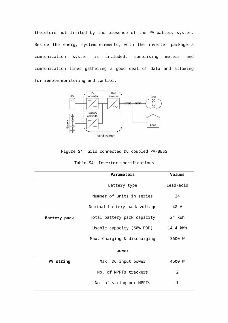
limited by the presence of the PV-battery system. Beside the energy system elements, with the
inverter package a communication system is included, comprising meters and communication
lines gathering a good deal of data and allowing for remote monitoring and control.

Figure S4: Grid connected DC coupled PV-BESS
Table S4: Inverter specifications
Parameters Values
Battery pack
Battery type Lead-acid
Number of units in series 24
Nominal battery pack voltage 48 V
Total battery pack capacity 24 kWh
Usable capacity (60% DOD) 14.4 kWh
Max. Charging & discharging power 3600 W
PV string
Max. DC input power 4600 W
No. of MPPTs trackers 2
No. of string per MPPTs tracker 1
AC output
Max. apparent power output to grids 3680 VA
Max. apparent power from grids 7360 VA
Max. apparent power output (backup) 3680 VA
EfficiencyMax. battery to load efficiency 94%
MPPT efficiency 99.9%
The most important feature of the inverter is its capability to manage the energy flows, as it is
equipped with a built-in Energy Management System. This work is carried out considering the
“General mode”, which maximizes self-consumption from a static energetic point of view, without
any consideration on the economic side (such as considering the varying electricity tariffs) or on
the dynamic energy consumption side. PV generated energy firstly meet the local demand. In case
of excess energy, it charges the battery and only then is sold to the grid. Battery will only charge
with excess solar power, not by grid. When PV power is lower than load, battery will discharge. If
PV and battery do not supply enough power to meet demand, the Grid supplies the difference.