· web viewtable 1 member contribution the final section of this document (5) is the...
TRANSCRIPT

TABLE of CONTENTSTABLE of TABLESTABLE of FIGURESEXECUTIVE SUMMARY
1.0 This Document…2.0 About NOMS
PROJECT DESCRIPTION1.0 Motivation & Goals2.0 Objectives3.0 Requirements and Specifications
RESEARCH FOR DESIGN1.0 Existing & Similar Products
1.1 Beyond WBYMW11.2 Nathan Broadbent’s version1.3 Hobart’s Combi Oven1.4 Knight Watch Security1.5 Smidge
2.0 Relevant Technologies2.1 Microcontrollers2.2 Barcode and QR Code Scanners2.3 LCD Touchscreens
3.0 Strategic Components3.1 Single-Band vs. Dual-Band Wi-Fi3.2 Embedded Wi-Fi vs. Installed Wi-Fi Shields3.3 Single vs. Multiple Embedded Systems
4.0 Possible Architectures
PROJECT HARDWARE & SOFTWARE DETAILS1.0Power Management
1.1Power Systems1.1.1 Basis of Design1.1.2 Food Preparation Research1.1.3 Heating Food with the Microwave
1.2Electrical Research1.2.1 Linear Power Supply Design1.2.2 Full Wave Rectifier1.2.3 Circuit Design Full Wave Rectifier1.2.4 Multiple Winding Transformers1.2.5 Full Wave Bridge Rectifier Circuit Design1.2.6 Voltage Doubler1.2.7 Villard Circuit1.2.8 Electric Motor1.2.9 Induction Motor
i

1.2.10 Synchronous Motor1.2.11 Brushed DC Motor1.2.12 Brushless DC Motor1.2.13 Stepper DC Motor1.2.14 Magnetron1.2.15 Power Supply Stability1.2.16 Power Output Requirments
1.3AC Components1.3.1 Magnetron1.3.2 Turntable1.3.3 Fan Motor1.3.4 Lights1.3.5 AC/DC Tranformer1.3.6 Buzzer1.3.7 Summary of High Power Consumption Devices
1.4DC Components1.4.1 Controllers1.4.2 Camera1.4.3 Touchscreen1.4.4 Relay1.4.5 Solid-State Relays vs. Electro-Mechanical Relays1.4.6 Relay Switch Selection Process1.4.7 Regulator1.4.8 Summary of Low Power Consumption Devices
1.5Power Systems Testing1.5.1 High Voltage Power Protection and Feedback1.5.2 Low Voltage Power Monitoring and Feedback1.5.3 Low Voltage Power Step-Down
2.0System Controller2.1Requirements and Specifications2.2Circuit Card Assembly
3.0Embedded Wi-Fi3.1Functional Requirements/Design Considerations3.2Existing Systems Choices
3.2.1 XBee Wi-Fi Module3.2.2 CC3000 SimpleLink Wi-Fi Module from TI
3.3Subsystem Overview3.4Configuration of the CC30003.5Parts Acquisition
4.0Online Database4.1Functional Requirements4.2Existing Database Choices4.3Creating a Server4.4 Integration of the Database with the Wi-Fi SOC4.5Acquiring and IP Address4.6Querying the Database
ii

5.0Camera & Optics System5.1Conditions of Operation & Environment
5.1.1 Magnetic Radiation5.1.2 High Temperatures5.1.3 Heating Food5.1.4 Food Splatter
5.2Protection & Housing Design5.2.1 Why a Recessed Camera?5.2.2 Housing Cover5.2.3 Housing Body
5.3Optics & Lenses5.3.1 Aperture5.3.2 Focal Length5.3.3 Circle of Confusion5.3.4 Depth of Field5.3.5 Viewing Angle
5.4CMOS Camera Operation5.4.1 Light-To-Charge Conversion5.4.2 Lighting Conditions5.4.3 Pixel Dimension Optimization5.4.4 Clock-Out & Shutter Time
5.5Image Quality Control5.5.1 Black & White Value Optimization5.5.2 Value Binning5.5.3 Image Sharpness
5.6Quantifying Sharpness & Grayscale-Valued Optimization5.6.1 Measuring Effectiveness of Focus & Lens System
5.7Video Format Qualities5.7.1 VGA CMOS Camera Operation5.7.2 VGA Line Data Transmission
5.8VGA CMOS Camera Features5.8.1 Color Flexibility5.8.2 60 Hz Elimination5.8.3 White Balance5.8.4 Anti-Blooming5.8.5 I2C Compatibility5.8.6 Operating System Support5.8.7 Cost-Effectiveness5.8.8 Lens Options
6.0UPC Codes6.1Motivation for Use6.2UPC Standards6.3EAN-13 Specification and Composition6.4UPC Capture
6.4.1 Grayscale Conversion6.4.2 Filter
iii

6.4.3 Black and White Conversion6.4.4 Deskew6.4.5 Crop6.4.6 UPC Decoding6.4.7 Check Digit
6.5Programming Considerations7.0QR Codes
7.1Motivation for Use7.2QR Standard7.3QR Specification7.4QR Composition7.5QR Generation7.6QR Code Capture7.7QR Decoding
8.0User Interface9.0System Display & Touchscreen
9.1Requirements9.2LCD Selection9.3Programming the LCD9.4LCD & System Controller Interconnect
SUMMARY OF HARDWARE AND SOFTWARE1.0 Hardware2.0 Software
PROTOTYPE CONSTRUCTION1.0 Parts Acquisition & Bill of Materials2.0 PCB Vendor & Assembly3.0 Final Coding Plan
PROTOTYPE TESTING1.0 Test Environments2.0 Specific Testing3.0 Conclusion
ADMINISTRATIVE CONTENT1.0 Budget2.0 Budget Discussion3.0 The Inspiration for NOMS4.0 Milestone Discussion5.0 Semester 1: Senior Design 1 Milestones6.0 Semester 2: Senior Design 2 Milestones7.0 About Us8.0 History of Easily-Prepared Food
APPENDICIES
iv

A. PermissionsB. References
v

TABLE of TABLESTable 1 Member ContributionTable 2 Frozen Food ResearchTable 3 Microwave DataTable 4 Magnetron Power DataTable 5 Turntable Power DataTable 6 Fan Motor Power DataTable 7 Light Power DataTable 8 AC/DC Transformer Power DataTable 9 Buzzer Power DataTable 10 Summary of High Power ConsumptionTable 11 Microcontroller Power DataTable 12 Camera Power DataTable 13 Touch Screen Power DataTable 14 Regulator Power DataTable 15 Summary of Low Power ConsumptionTable 16 Microcontroller ComparisonTable 17 Gamma 1 ValuesTable 18 Gamma 1.5 ValuesTable 19 Gamma 0.5 ValuesTable 20 Gamma Unity ValuesTable 21 Gamma 1.5 ValuesTable 22 Gamma 0.5 ValuesTable 23 Common Resolution for Aspect RatiosTable 24 VGA Line DataTable 25 Number Sets A, B, and CTable 26 Implicit Digit EncodingTable 27 Cook Data FormatTable 28 Interconnection ProtocolTable 29 BudgetTable 30 Semester 1 Milestones
vi

TABLE of FIGURESFigure 1 High Level State Transition DiagramFigure 2 NOMS Sub-Systems DiagramFigure 3 Typical Kitchen Electric LayoutFigure 4 Frozen Food ResearchFigure 5 AC WaveformFigure 6 Full Wave Rectifier OutputFigure 7 Full Wave Rectifier Circuit DesignFigure 8 Multiple Transformer WindingsFigure 9 Full Wave Bridge Rectifier Circuit Figure 10 Full Wave Bridge Rectifier OutputFigure 11 Villard Circuit DesignFigure 12 Villard Circuit OutputFigure 13 CEMBA and ITIC CurveFigure 14 Microwave Circuit SchematicFigure 15 High Voltage Protection CircuitFigure 16 Low Voltage Monitor PackageFigure 17 Low Voltage Power Step DownFigure 18 WiFi Block DiagramFigure 19 Database StructureFigure 20 Database Structure Flexibility Figure 21 Database CommunicationsFigure 22 Network TopologyFigure 23 Peer to Peer Figure 24 General Housing Design ConceptFigure 25 Perfect Thin Lens ModelFigure 26 AperatureFigure 27 Focal LengthFigure 28 Gamma-Corrected Contrast RatiosFigure 29 Gamma UnityFigure 30 Gamma 1.5Figure 31 Gamma 0.5Figure 32 EAN-13 Symbology Figure 33 EAN-13 CompositionFigure 34 QR Code StructureFigure 35 QR Code LayoutFigure 36 Home ScreenFigure 37 Manual EntryFigure 38 ScanningFigure 39 OverrideFigure 40 Save CustomFigure 41 Cook ScreenFigure 42 Log ScreenFigure 43 Servings
vii

Figure 44 System SettingsFigure 45 AppearanceFigure 46 Date/TimeFigure 47 Time EntryFigure 48 Month EntryFigure 49 Day EntryFigure 50 Year EntryFigure 51 ProfilesFigure 52 Name EntryFigure 53 Email EntryFigure 54 MyFitnessPalFigure 55 UI FlowFigure 56 Budget Figure 57 Semester 2 Milestones
viii

Executive Summary
The Nutritional Object-Identifying Microwave System (NOMS) is an improved microwave that automatically cooks food items based on identifying UPC/QR codes located on the food packaging. Current microwaves require users to input cook times and power levels in order to perform food preparation. We believe that as technology has advanced there has been a severe oversight in the realm of cookware. There are automated home systems, automated traffic signals, automated systems in cars, but no automated systems in the household kitchen. NOMS corrects this oversight in a simple and profitable way. The following figure (figure 1) shows a simple high-level state-transition diagram of the NOMS.
Figure 1 – High-Level State-Transition Diagram
NOMS makes use of cameras designed to look for UPC codes and/or QR codes. The user may choose to either scan the food in using one of the cameras or just enter the time and power level traditionally on the LCD screen. For the former, once a code has been identified the system searches the recently used codes in the cache for cook time and power level. If the code is found then the user will be
1

asked if they want to cook the food according to the time and power levels found. If the user chooses ‘Yes’ then the system will turn on the microwave’s motor drive, magnetron, and lights at the specified level and time. If the user does not want to use that time or power level they will be able to use the traditional method of inputting time and power at which point the new information will be saved in the cache for future use. If, however, the correct code is not found in the cache then the system will send the code out to the NOMS website to find the proper cook time and power level. If the code is found, the Wi-Fi shield will send the data back to the system for use. If the code is not found the Wi-Fi shield will send a message back to the system showing that no valid data was found. The online database will also track searches that are not successful in order to provide future maintainability. It is at the point that the database online also does not provide cook time and power level that the user will have to resort to the traditional method of using the microwave.
Whenever the microwave has been turned on to heat food up and there is a code that was not found in the cache the system will save all of those settings and the code into the cache for future reference. In this way NOMS will be able to “learn” the users’ eating habits and be adaptable for the individual user.
1.0 This Document…In the next section of this document, the Project Description, we will continue to further describe NOMS. We will summarize the origin of this project idea, the motivation and goals of the team and its project, and the accompanying requirements and specifications. The project description is what the group will use as a skeleton for the project. It provides a reference point that will be followed by each group member so that the completed project will be a visible, functional representation of what has been described.
In Research For Design we will show some existing technologies that we have researched in order to get a starting point for our project. We will show relevant work and products, components that we have chosen and a justification for why each component was selected for NOMS. Finally we will discuss the architecture we have selected for the design of NOMS
The Project Hardware and Software Details section will consist of the majority of this report, being the research aspect. As our group looked at how to take on the idea for NOMS we decided to break the project up into distinct parts for simplification. This helped us to divide up the individual workloads and to ensure that we didn’t miss any important steps in designing and developing NOMS. We chose to discuss these research topics in the specified order based on the flow of how NOMS will work. We begin by discussing the power management system which will in turn power the microcontroller. This microcontroller will have the Wi-Fi chip added onto it, first as a plug-and-play device and then finally surface mounted. The Wi-Fi chip will interface between the microcontroller and the online database so the database section will come next. After this we will discuss the
2

camera and optics system which is where the EAN-13 codes will be coming from. These EAN-13 codes will be derived from the decoded UPC and QR codes which are further discussed. Finally we will end the research discussion with a brief discussion on the LCD touchscreen which will serve as the user interface allowing the user to use the NOMS system.
Following the research aspects of this document we will give a Summary of Hardware and Software that will be used in the design process of NOMS.
Then we will give a discussion on the prototype plans that we have created in terms of the Prototype Construction and then the Prototype Testing plan.
At the end of this document there will be some Administrative Content that will cover the budget and milestones of NOMS’ design followed by the Appendices with all the permissions, datasheets, and software.
2.0 About NOMSThe group decided in the early stages of planning and design to take a functional microwave and make additions to it in order to achieve our goal for the automated system. NOMS has been divided into modular pieces and each group member is specifically responsible for one or more tasks/subsystems. The diagram to follow (Figure 2) shows all subsystems, each of which is in communication with the Central Controller or System on Chip (SOC).
3

Figure 2– NOMS Subsystems Diagram
Shown below is the distribution of tasks to individuals in the group with the section of this document that each topic is discussed. While each member is specifically responsible for particular tasks it is understood that these tasks will overlap in some areas requiring collaboration and teamwork.
Nakiesa Faraji-Tajrishi Power Systems (4.5)Tim Miller Wi-Fi (4.1) and Online Database (4.2)Tom Mizell Camera Systems and Haptics (4.6)Jared Wach User Interface and SOC (4.3-4.4)
Table 1 Member Contribution
The final section of this document (5) is the Administrative Content covering group dynamics such as milestones to be reached and financial decisions involved in budgeting.
4

Project Description
1.0 Motivation & GoalsOriginally the idea for The Nutritional Object-Identifying Microwave System (NOMS) was one of the group members’ own, Jared Wach. Having worked with Jared in several other classes prior to Senior Design the group members decided it would benefit each person to work together to achieve our goals. Once each person agreed to be in the group we discussed different ideas for a project, finally choosing to go with Jared’s idea for the automatic microwave.
In addition the group had various degrees of experience working with electrical systems, programmable microcontrollers, and wireless internet. Each member found a particular area of interest in the project such that their theoretical knowledge could be put to use. The computer engineers found particular interest in the embedded System on Chip and integrating a wireless internet component into it. The electrical engineers found similar interest in devising a way to power each added component and building the embedded system itself.
The group was also motivated by the desire to design something challenging. The idea for NOMS seemed like just the right balance of feasibility and difficulty. The idea to create an automated microwave didn’t sound too different from previous Senior Design projects we heard about which confirmed to us that this project had the potential to be a success. In addition, had we chosen to design something simpler we might not have had the opportunity to learn as much or apply the previous knowledge we’ve accrued in our college careers. We look forward to being able to complete this project, look back on our hard work, and see the fruit of our labors in the complete NOMS Senior Design project.
One further motivation and goal of the group was to create something we had never seen before. To this point we still have not found another Senior Design project identical to this one nor have we found any products like it in the market. This gave NOMS a uniqueness that we felt would add to the value of this project. The value of this project may also transcend sentimentality to the point of profitability. Were we to market this idea it seems possible and probable that companies would be interested in using this idea to advertise their products to users. Though we do not presently intend to market this project this does add to the value of the project.
2.0 ObjectivesOur objectives are to create a functional, automated microwave that makes use of wireless internet and an online database created and maintained by the group. Our goal is to design a system that is intuitive enough that the average user will be able to use NOMS without too much previous instruction. In addition, our objective is to create a system that not only works well but also has aesthetic
5

appeal. Finally, we are going to create a system that is as cost-effective as possible. It is certainly possible to create this system with expensive parts that are very simple to implement and use, however our goal is to keep this system as cheap as possible to show its potential for commercial production and keep the project itself as challenging as possible.
3.0 Requirements & SpecificationsOne aspect of NOMS that will be focused on specifically is the energy efficiency of the system. In order to maximize efficiency we will pay special attention to how much power is used by each added subsystem such as the LCD touchscreen, the embedded system on chip, and the normal microwave parts. Once each part’s power needs are known we will match our power output from the microwave’s pre-existing system with our additional modifications.
Another requirement for NOMS is that it will be easy to use. This may be a somewhat vague-sounding requirement but will be focused upon further as to how we will verify that NOMS is easy enough for the common user to use. This is an important attribute to focus on since a working version could be created but not be particularly intuitve.
NOMS shall make use of an LCD touchscreen for interface between the user and the system. This display will be both an output and an input and shall be pleasing to the eye and easy to use as discussed previously. The LCD shall be embedded into the front of the microwave where the touchpad would normally be. It shall be smaller than a three inch wide by four inch tall screen that is controlled by the system on chip (SOC).
NOMS will also use wireless communication between the system on chip (SOC) and an online database. The wireless communication will take place from the SOC and will be installed onto the system by the design team. The team will most likely use the TI CC3000 for wireless internet communication.
In order for the wireless communication to work there will need to be a working online database with a corresponding database management system. There are several choices for this database and its managements system as discussed further in the Hardware and Software Details section. This database will need to keep track of unique EAN-13 codes which will identify each food item. Each food item will contain multiple instructions for cook time and power levels to achieve optimal cooking of the food item. For example a Hot Pocket may need to be cooked at full power for one minute, then 30 more seconds at half power, followed by a full minute with the magnetron disabled for cooling.
In order to search the online database for the cooking instructions of a given food item the item will need to have the EAN-13 code for that item on the packaging. This code will be scanned in from a camera on the outside of the microwave that will also be installed into the microwave. There will be at least one
6

camera/digitizer installed on the microwave. This camera will be installed on the outside of the microwave just below the LCD touchscreen. The second camera that is a “like-to-have” but not a must will be installed on the inside of the microwave where it will be embedded into the roof of the microwave and look down on the food. This would be useful for food items with EAN-13 codes to be read from the top of the food item. The implementation of this camera will be pursued at a later time in the design process as time permits.
7
Research for Design
1.0 Existing & Similar Products1.1 Beyond WBYMW1 850-Watt Microwave Oven with
Barcode ScanningA company named “Beyond” released a product similar to what we are creating that they called the “Beyond Microwave Oven”. This product made use of a barcode scanner. The website that sells Beyond’s microwaves boasts that it has “Over 4000 UPCs preprogrammed”. It can also store new barcodes that aren’t preprogrammed and has an LCD screen.
The major differences between this product and our project are: NOMS uses QR codes as well as barcode scanning NOMS uses cameras instead of a barcode scanner NOMS directly uses internet each time a code is not found so no updating is
required
In addition, we previously stated that we know of no existing smart microwaves that are on the market. This still remains true given that this product has been discontinued for unknown reasons. The website no longer sells Beyond’s smart microwaves and there are only a few to be found on bargain appliance websites. The fact that this product did not catch on may be cause for concern, though the appliance itself seems to have worked very well as seen in many comment sections about the appliance. It is possible that this product was created a little before the time that people were ready for it, in which case we expect to see more like it on the market in the near future as technology continues to expand and “smart” appliances continue to become more popular in homes. The link below shows Beyond’s smart microwave.[1]
1.2 Nathan Broadbent’s versionAgain we discovered that someone else had a similar idea for a “smart microwave”. This time a gentleman by the name of Nathan Broadbent took the idea he read about on a popular social website and decided that he could build it. Mr. Broadbent redesigned the touchpad, added voice command control, and implemented wireless internet into the system. He used a barcode scanner, an online database, and a microcontroller called Raspberry Pi.[2]
The major differences between Nathan Broadbent’s design and ours are: NOMS uses cameras instead of a barcode scanner NOMS will not use a Raspberry Pi, but will instead upon request of the client (Dr.
Richie) use a System on Chip (SOC) Wi-Fi will be installed on the System on Chip
8

1.3 Hobart’s Combi Oven with Barcode ScannersIn the search for similar technologies we also discovered that this idea has gone to other appliances like the oven. A company named Hobart created their take on a “smart” oven called a Combi Oven with Barcode Scanners. This appliance also uses a barcode scanner and their system will even create a barcode for a recipe not found in their database. The oven has many features that are common to ovens like cooking modes and gas/electric types. This product does appear to be built for commercial use however.[3]
Hobart’s oven is similar to NOMS in many ways but NOMS: Uses QR codes as well as barcode scanning Is for both commercial and household use
1.4 Knight Watch SecurityIn addition to realms outside of the University of Central Florida there are a few similar projects from previous Senior Design classes that we are able to look at and learn from.
In searching for previous Senior Design projects that would be similar to ours we looked for any projects that made use of wireless internet. This would be a good starting point for gathering ideas on how to implement our wireless internet between the SOC and online database. We did discover a group from the Senior Design Fall 2012-Spring 2013 class whose project was called Knight Watch Security. In the end though, this team had pre-existing onboard Wi-Fi on their SOC which was different from the requirements given to our group. The link to that project is given below.[4]
1.5 SmidgeLastly, we also became aware of a project similar in concept called “Smidge”. This project was a “smart” fridge. It connected to the internet, had a barcode scanner and had many other features. Dr. Richie praised the team for their design and completion when discussing our project so we knew it would be wise to consider Smidge’s approach to research and design.[5]
2.0 Relevant Technologies2.1 MicrocontrollersBased on the project description of NOMS we will certainly need something to control the microwave itself and its interaction with the online database among possibly several other aspects of NOMS that need controlling.
Microcontrollers are basically small computers that are embedded into other systems in order to perform specific tasks. Common uses of microcontrollers are in TVs, cars, and even microwaves LCD touchscreens. Each of these
9
microcontrollers performs a specific task within its system, as will be the case in NOMS. In addition microcontrollers are a low-cost, low-power, and small solution for what we are trying to accomplish. These microcontrollers are also usually outfitted with a simple programming language like “BASIC” or “Processing” which makes programming the microcontroller relatively simple.
A few examples of microcontrollers used for tasks such as what NOMS does are the Arduino, Raspberry Pi, and BeagleBone. In fact, Nathan Broadbent’s barcode scanning microwave (section 3.1) used a Raspberry Pi. For our project we will design our own embedded system based on designs in Texas Instruments products, Arduino, and Raspberry Pi. This will help guide our design process and add to the potential systems for prototyping.[6]
2.2 Barcode and QR Code ScannersBarcodes have been in use for many years now and are also known as UPC bar codes. The barcode is a fairly straightforward tool used in tracking and identifying items. Since almost any food that requires cooking is accompanied by a UPC bar code this is a great way to identify the food items we wish to keep track of. In order to scan a UPC code we can either use a laser scanner as is common to commercial use in stores everywhere in America, or we can use a camera to capture an image of the barcode and use the captured image to derive the identifying information.
QR codes are a newer identifying piece of information that accompanies some items. In addition to identifying the food item, QR codes also contain other information that can make connecting to the internet unnecessary. The main difficulty with QR codes is that they require a camera to capture the image and then process the image in order to derive the information given in each code. This can be a fairly difficult process to implement but is used widely as well. These technologies are discussed in much more detail in the Hardware and Software Details section.
2.3 LCD TouchscreensLCD touchscreens have become very popular in today’s world. LCD screens are everywhere from TVs to kitchen appliances to our smartphones. Due to the common use of these technological tools we find it desirable to integrate one into our smart microwave. LCD touchscreens offer a variety of special features that traditional touchpads do not such as low power usage, visual appeal, and re-programmability. It is for these reasons that NOMS will seek to make use of LCD touchscreens. In fact, these user interfaces have also become relatively cheap and easy to buy, making them a good choice for NOMS.
The only concern for our group is that oftentimes LCD touchscreens have their own controller that requires its own programming. This being the case we will be adding to the workload of the design team when we design the LCD touchscreen subsystem and integrate it with the rest of the system. It is in our best interests,
10

therefore, to find a touchscreen that uses a programming language similar to one that the group is familiar with such as C or JAVA. This topic will be further explored in the Hardware and Software Details section.
3.0 Strategic Components3.1 Single-Band vs. Dual-Band Wi-FiWhen the group originally decided to create NOMS we decided that it would have to make use of a wireless internet connection in order for it to be cutting-edge. We immediately began researching embedded systems with onboard Wi-Fi. As we researched we became aware of a strange phenomenon in which microwave ovens have been claimed to interfere with Wi-Fi. This isn’t actually as strange as it might sound though. Traditionally Wi-Fi uses the 2.4 GHz frequency band which is usually reserved for that particular device. Microwave ovens, however, actually sweep across various frequencies briefly causing serious interference and data errors across Wi-Fi. This sounded like a pretty major problem for the NOMS team. We discovered that a quick solution might be to get a dual-band Wi-Fi system so that we could avoid interference while the microwave was on. A few weeks later we decided that instead of switching from single-band to dual-band Wi-Fi we could simply change the way that NOMS operates. Since Wi-Fi can be interfered with by the microwave due to the magnetron’s waves, we simply needed to make sure that the Wi-Fi does not do anything important while the microwave is on. Any messages or information gathered from the online database will need to be done BEFORE the microwave is turned on. Once the microwave is turned on the Wi-Fi needs to be in a neutral state waiting for its turn to function again. If ever NOMS were to include short advertisements on the LCD we would simply need to switch over to the dual-band Wi-Fi.
3.2 Embedded Wi-Fi vs. Installed Wi-Fi ShieldsAnother initial idea the team had was to start the project off with an embedded system that already had Wi-Fi built into it. This would simplify the project to some degree, but with four group members instead of three we decided it would over-simplify the work too much and wouldn’t challenge each member enough. This conclusion was reached mutually after discussion with Dr. Richie who also encouraged the team to build the embedded system instead of simply buying one. This lead to the decision to forego using an gs as a solution for the final project. We may, however, decide to prototype NOMS at the early stages of development in order to have parallel tasks running at the same time. With a working prototype we could test the database management system and all power systems running to the embedded system while the SOC is being designed and developed by the team.
3.3 Single vs. Multiple Embedded SystemsOne thing the NOMS team wanted to do in order to keep good testability and maintainability throughout the project was to keep tasks and subsystems as
11

modular as possible. In order to achieve this modularity we decided at first to use multiple embedded systems: one for handling all Wi-Fi and database related tasks and the other system to handle all other tasks. The former would actually communicate with the latter which would be the main SOC. Though this compartmentalized the work to some degree it actually separated the group too much in workload and made the task much more difficult to complete, especially after deciding not to use a microcontroller like an Arduino. The conclusion of the matter is that we have decided to run all tasks through one self-designed System on Chip. This will encourage more teamwork in the group, higher productivity, and a greater probability for success.
4.0 Possible ArchitecturesIn considering multiple choices for architectures to use in the embedded system (SOC) we considered MSP430 and ARM.
The MSP430 was initially attractive because each member of the group had actually worked with the MSP430 in a previous class. Programming the MSP430 would be something we could do rather easily having a fair amount of experience working with it. This is both a good and a bad reason to choose MSP430 since we want to be able to achieve our goals but also be challenged and put real work into NOMS.
ARM, by contrast, was a solution that the group was not too familiar with. But as we researched more about ARM’s architecture we realized that it offered more flexibility than the MSP430. There are more options in the ARM architecture than there are in MSP430’s architecture just because of the design itself. This was important since the NOMS system isn’t completely and finally designed yet and we considered the probability that the design would be changing as we implemented it. This being the case flexibility was very important to us with architecture. In addition we learned in our research of ARM that it is a highly used industry standard that would give us valuable insight and experience in the world of microcontrollers.
In conclusion, we decided that using ARM architecture would be our best solution. Based on this conclusion we have decided to seek out a microcontroller of this kind.
12

Project Hardware & Software Details
1.0 Power Management1.1 Power SystemsThe main objective of the NOMS power system is to provide low voltage power to the clock, controllers, cameras, and Wi-Fi, as well as supply high voltage to the magnetron, fan, the buzzer, light, turntable, transformers for the magnetron and low voltage loads. Typically utilities provide 120 V at residential wall outlets. The utilities are mandated by Public Service Commission to maintain the voltage at +/- 5%, which means the voltage runs from 114 V to 126 V. The Public Service Commission is in charge of regulating the electricity, natural gas, water and waste water, and telecommunications for each state. As far as electricity is concerned, the Public Service Commission is responsible for everything from providing reliable service to making sure they are in compliance with new construction safety codes for distribution of power. With this in mind, we can expect to design this project with consistent 120 V AC power supply coming from the wall.
For this project we will use 120 V as our base power source for incoming power and high voltage side of equipment, and select 5 V and 12 V DC for low voltage or control voltage. The 5V system is commonly used in small appliance circuits. The high voltage devices, including the magnetron, fan, lights, and turntable, high voltage transformer and AC/DC transformer are designed to operate at 120V and will not require voltage regulation.
For residential service, utilities provides 120/240 V circuit A typical house has 150amps – 200amps service that is either overhead or underground. Often multiple outlets are designed and connected to either 15 or 20 amp circuits. The National Electric Code (NEC) allows contractors and designers to connect up to 6 outlets to a single circuit. Most house hold outlets are rated at 15 amps due to cost saving measures by the contractor. Occasionally, one would encounter a 20 amp outlet in a residential home. [7]
The NEC is a group of rules and policies that govern the installation of electrical devices for residential and commercial projects. The NEC is recognized nationwide and adopted by all state and municipal governments. In the state of Florida, we have adopted the 2010 Florida Building Code, which is the governing document that is used to establish the laws for residential and construction in Florida. Within the 2010 Building code, we also adhere to the 2008 NEC Building Code. [7]
The NEC also requires each kitchen to be served by two separate circuits. Often in a new construction a separate circuit is provided for a microwave; however, in older homes there is not a designated circuit for microwave. This means that the
13

unit will be connected to an existing kitchen circuit along with other kitchen appliances. If the circuit is not connected properly, it can cause an overload in kitchen circuits. [7] The image below describes a typical kitchen electrical layout, adhering to the description listed above.
Figure 3 Typical Kitchen Electric :Layout Figure Obtained With Permission by EPG Engineering
14
The 120V wall outlet voltage is RMS value for the voltage. The peak voltage is RMS value multiplied by square root of 2, which is 170 V. This is the voltage that applied to all high voltage devices, including the AC/DC transformer. The resulting output of the transformer is 17 V AC that is fed through rectifier to create 17 V DC output. The 17 V DC flows through the regulator, where the 17 V is stepped down to 5 V.
1.1.1Basis of DesignFood manufactures are challenged to produce a product that meets the majority of their customers’ need. This challenge is further complicated with the fact the each customer does not own a standard power output microwave to cook their meal. Therefore cooking instructions must reflect the assortment of customers whose microwaves range from using a low power microwave of 600 W to a high output power unit that produces 1250 W. In order to meet safety requirements as well as customer’s needs, most microwave food companies have established a standard of 1100 W as the basis of cooking instructions. This creates a new challenge for most customers, as often times the microwave food does not include alternative cooking methods for microwaves which do not fit the 1100 W requirements. These consumers must take out a calculator and determining the unit conversion to calculate the correct cooking time for their appliance for each specific microwavable food.
For our project we have decided to create the NOMS system with the necessary intelligence to prevent customers from dealing with complications associated with guessing the time conversion. In order for the look-up data to accurately reflect cooking times, we must design our microwave so it is capable of converting the cooking times to account for the 1100W output instructions. With 15 A maximum circuit capacities, all design decisions must account for the power restrictions of the microwave so we would not overload existing circuits.
All small appliances must be designed to operate with 15amp circuit, meaning that total power consumption must be less than 1800 watt (assuming 120v power base). In our design, we plan to limit our total design watt budget to 1680 watts or 14 amps. To determine the overall watts budget, we have grouped the typical loads into two groups: low voltage needing 5 volt, and high voltage needing 120v.
1.1.2 Food Preparation Research In order to determine the amount of output power NOMS would require, we went to the grocery store and sampled some of the common frozen food items to see the required cooking wattage. By and large it seems that companies are creating cooking instructions to cater to people with greater than 1000 W microwaves. There were a few cases which listed alternative wattage cooking instructions, but they were in the minority. Considering that NOMS is a product whose selling point is marketing the automatic preparation of food, we need to comply with the common practices of the industry. Since most of the data we collected about
15

microwave dinners calls for greater than 1000 watts to cook the food, we must implement this in our design.
The main concern of NOMS as an autonomous microwave is to prevent instances where frozen food is not cooked thoroughly enough and our consumers fall ill from food sickness. This is a valid concern, as most of the frozen dinners found in the supermarket contain some form of meat. If the meat is not heated to proper temperatures, the consumer can fall ill due to salmonella or even E.coli. In October 2008, NBC and the Associated Press covered a story regarding an increasing problem with consumers eating undercooked microwave food. The article cited 325,000 people each year that are hospitalized from food illness. The article addressed an outbreak in salmonella and E.coli in frozen dinners within the past couple years and stated that corporations have increased their mandatory cooking power required for microwaved food as a results of these outbreaks of illness. [8]
This increase in mandatory cooking power is reflected in the data we collected in the supermarket concerning preparation instructions for frozen dinners. The data provided in the table below comes from frozen food package cooking instructions we found during our trip to the supermarket.
Food Cooking Instruction Required Microwave Wattage
Garden Lites Carrot Raisin Souffle 1000 WKashi Chicken and Chipotle BBQ 1100 WJimmy Dean Biscuit, Sausage, Egg & Cheese 1100 WBoston Market Swedish Meatballs 1100 WHealthy Choice Chicken Parmigiana 1100 WLean Cuisine Chicken Teriyaki Stir Fry 1100 WMarie Callender’s Sweet and Sour Chicken 1100 WSmart Ones Vegetable Fried Rice 1100 WStouffer’s Chicken Lasagna 1100 WBrown N’Serve Lite Original Sausage Links 1100 WMoringstar Chik’n Nuggets 1100 WKidfresh Muy Cheesy Quesadillas 1100 WEthnic Gourmet Chicken Korma 1000 WHealth is Wealth Spinach Munchees 1000 WBoca Savory Mushroom Mozzarella Veggie Patties
600 W – 1100 W
Stouffer’s Veal Parmigiana 1100 WTable 2 Frozen Food Research
16

A select number of pictures gathered from the supermarket trip of the frozen dinner cooking instructions are provided below, as validation for the data we provided in the table.
Figure 4 Frozen Food Research
As clearly displayed in the table above, it seems most of the cooking instructions called for over 1000W output power in microwaves. With that information in mind, we decided it would be prudent to determine how common it would be for a consumer to purchase a microwave under 1000W. If most microwaves for sale currently had over 1000 W output power, we would not consider designing a microwave with less output power. We visited a local electronic store to see what wattage models were for sale on the floor. From this trip, we determined that people can purchase a microwave from 700 W to 1200 W. Typically the 700 W microwaves are well below $100 while the 1200 W microwaves tended to be pricey. Considering the number of options below 1000W output power, it is safe to assume that not all households will purchase microwaves with over 1000W output power. Therefore, NOMS should consider creating a microwave that will work at multiple output power wattages. The data in the chart below was
17
obtained during our visit to the electronic store. The chart shows some of the microwaves available for consumer purchase.
Microwave Brand, Model, Output Power PriceOster, OGG3701, 700W $79.99Haier, HMC0903SEES, 900W $99.99Franklin Chef, FC1270W, 1000W $109.99GE, PEB7226SFSS, 1100W $339.99Sharp, R651ZS, 1200 W $189.99KitchenAid, KCMS2255BSS, 1200W $539.99Whirlpool, WMC50522AS, 1200W $269.99Panasonic, NN-SE982S, 1250W $309.99
Table 3 Microwave Data
The prices above reflect standalone microwave units and not the ones that are installed into the kitchen wall, otherwise known as “Over-the-Range”. “Over the Range” microwaves cost substantially more and will not be considered for this project. It is possible that a consumer who is interested in purchasing a microwave will consider microwaves with less than 1100W output, due to cost. With the consumer in mind, we have decided to create a conversion table for microwave cooking times. This will be useful for the cases where the microwave output wattage does not agree with the cooking instructions. This would make NOMS a more universally applicable system and would increase appeal to the consumers.
In order to determine a conversion equation, we examined some products which listed cooking instructions for multiple output cooking power wattages. From this information we were able to find a relationship between the times and the output power wattage. The equation is as follows:
Adjusted cooking time=(Required Output Power per Cooking InstructionsMicrowaveOutput Power )∗(instructioncookingtime)
Logically, this makes sense, as having a lower output power would require a longer cooking time. This equation is not considered perfect; however, it is a good place to start. We will be able to test the accuracy of this equation as we are testing the microwave. Additionally, we will have a feature built into NOMS where if something in the cooking instructions must be changed, NOMS has the capability to remember the changes and implement the new instructions the next time that item is placed into the microwave. It will also have the ability to remember user presets. For example, if someone likes their popcorn a little less popped, the next time NOMS reads that exact type of popcorn, it will remember the previously entered user settings and implement the new cooking instructions instead of referencing the manufacturer’s instructions.
18

1.1.3 Heating Food with the MicrowaveThe magnetron produces microwaves by converting the current into radio frequency waves. The radio waves produced by the magnetron are sent towards spinning metal fans inside the microwave. Microwaves will reflect off metal, so this will cause the microwaves to reflect off the fan and into the cooking chamber. A typical microwave cooking chamber is lined with metal for the same design purpose: to keep the microwaves bouncing around the chamber until they are ultimately absorbed. Microwaves are absorbed by water. Water is a polar molecule, which means one side is predominately positively charged while the other is predominately negatively charged. Indrocucing an electric field to a polarized molecule will cause the molecule to rotate. The electric field produced by the magnetron is oscillating, which means the water molecule will consistently rotate. Most microwaves attempt to operate at 2.45 GHz. This frequency oscillates at exactly the same amount of time it takes for water to rotate 180 degrees. This is considered the ideal speed since water cannot rotate any faster. [9]
The rotating water molecules are constantly bumping into the molecules around them, causing a transfer of kenetic energy. Kinetic energy is defined as the amount of work needed to accelerate a body of mass from rest, or E = ½ mv2. Kinetic energy can also be defined as temperature, as is the case for water. Increasing the kinetic energy of water will increase the temperature of the water molecule. The increase of temperature, or kinetic energy, in the water molecule will increase the internal temperature of the food.
The electric field at any point on the food is equal to the sum of the respective electric fields. If two electric fields line up perfectly so the peaks and valleys are aligned, they will create a larger electric field. The increased electric field allows the water molecules to gain more kinetic energy. The gain in kinetic energy will cause the internal temperature of the food to rise, and ultimately, get hotter. Sometimes the microwaves can interfere with each other, which causes the food to cook unevenly. If the waves line up in such a way that the peaks and valleys are on top of each other, this will cause the two to cancel and the electric field will be negated.When the electric field is negated there will not be energy available to increase the internal temperature of the food. [10]
As previously mentioned, the inside of the microwave is coated with metal. This allows for the molecules to bounce around, but it also provides oppoprtunities for the microwaves to create interferance with one and antother. The purpose of a rotating turntable in the microwave is to reduce the amount of interference the microwaves can create.
Another factor which determines cooking time is the amount of water present in a material, which is directly related to the ability of the molecules to rotate. The easier the it is for the water molecules to rotate, the quicker the food can cook.
19

Items that are frozen have less water molecules. This creates a condition in which it is harder for the molecules to rotate, which means there will be less kinetic energy created. Items that do not have many water molecules are also difficult to cook as there are less water molecules to rotate and ultimately less kinetic energy transferrance. [11]
Electrical Research
1.2.1 Linear Power Supply DesignIn order to design a linear power supply you need a transformer to step down 120 V AC, a rectifier to change the AC voltage to DC, and a capacitor to smooth out the signal. The first thing required when designing a linear power supply is to determine the output voltage and current needed. In this system, we will need 5 V at 1.8 Amps. From this, we will consider a linear regulator and bridge rectifier that can handle the current requirement. Finally, we need to consider a transformer that will create the desired step down voltage of 5 V. The research below was necessary to aid in the decision of what circuit component would be necessary to create the linear power supply design for the NOMS system.
1.2.2 Full Wave RectifierA Full Wave Rectifier converts alternating current signal (AC) to direct current signal (DC). The rectifier is composed of a system of diodes and transformers. The nature of a diode makes it ideal to use for rectification, which is the act of transforming AC voltage into DC voltage. Diodes are ideal because they only allow current to flow from the anode to cathode, but not in the reverse direction. When dealing with a larger input voltage, it is advantageous to use a power diode. Power diodes have a high forward current capability (kA) and a large reverse blocking voltage (kV). Since this project will deal with the high voltage transformer inside the microwave, we will consider power diodes within the Full Wave Rectifier. [12]
20

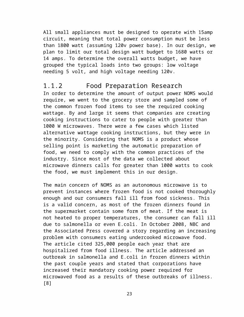
A Full Wave Rectifier takes in an AC waveform, like the one pictured below.
Figure 5 AC Waveform
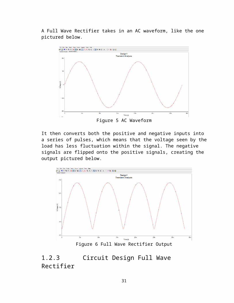
It then converts both the positive and negative inputs into a series of pulses, which means that the voltage seen by the load has less fluctuation within the signal. The negative signals are flipped onto the positive signals, creating the output pictured below.
Figure 6 Full Wave Rectifier Output
1.2.3 Circuit Design Full Wave RectifierIn order to achieve this output, a Full Wave rectifier is typically designed with two power diodes connected to a multiple winding transformer and load resistance. A multiple winding transformer contains more than one winding on the primary or secondary side connected by a common laminated core. The circuit diagram is pictured below.
21

Figure 7 Full Wave Rectifier Circuit Design
The circuit contains two diodes so that one diode delivers current to the load while the other diode remains off. This allows for only the positive signal cycle to supply current to the load. Since the output voltage is the sum of the two waveforms, the spaces between the half waves are covered by the waveform of the other diode. The sum of the waveforms creates an output twice as large across the output resistor. [12
1.2.4 Multiple Winding TransformersThe multiple winding transformers connect the primary windings to a high voltage or current supply and transform this input into a different secondary voltage. In order to use this kind of transformer, the voltage or current ratings must be identical in order to be connected. The image below shows the design of a multiple winding transformer.
Figure 8 Multiple Transformer Windings
The downfall of using a multiple winding transformer is a large transformer is needed to deal with the large output, which is expensive. It is also expensive to make sure the secondary windings are identical. A cheaper and more reasonable solution is to use a Full Wave Bridge Rectifier circuit, as this circuit does not require a center tapped transformer and it is also smaller circuit. [13]
22

1.2.5 Full Wave Bridge Rectifier Circuit DesignThe Full Wave Bridge Rectifier circuit uses four diodes connected in a closed loop. The secondary winding is connected to one side of the diode bridge and the load is connected to the output. At any given time, two diodes are on for each half cycle. In the circuti diagram below, D1/D2 are turned on for the negative cycle and D3/D4 are on for the positive cycle.
Figure 9 Full Wave Bridge Rectifier Circuit
This circuit setup allows for a larger mean DC output value with less fluctuation. The capacitor shown in parallel with the load, known as the smoothing capacitor, helps create a pseudo DC output. The smoothing capacitor is determined by two factors: the working voltage needs to be less than the no load output of the rectifier and the capacitance value needs to be larger to eliminate the fluctuation on the voltage. [14] The resulting output becomes more stable, like the picture below.
Figure 10 Full Wave Bridge Rectifier Output
The downfall of this circuit is that this circuit does not work well with low voltage power; however, this will not be a problem as the NOMS microwave design deals with a high voltage power.
1.2.6 Voltage DoublerVoltage doublers are used in AC to DC conversions. They take the input AC voltage and turn it into an output of the DC voltage twice as large as the input. A voltage doubler uses diodes as natural switches. Reference the previously discussed research in the Full Wave Rectifier section to see how diodes can be used as switches. Using a voltage doubler in a circuit allows for a smaller input
23
power to be converted into millions of volts to power some of the high energy components inside the microwave, such as the magnetron. This works because the voltage doubler allows for a wider voltage oscillation frequency to occur from a lower input voltage. We want to consider using a voltage doubler for the power systems design in this project. After doing some research, we came to the conclusion that of the voltage doubler circuits, we need to use a Villard Circuit in our power systems design.
1.2.7 Villard CircuitIn most microwave power system design, a Villard circuit is used as a voltage doubler. A Villard circuit consists of a capacitor and a diode. The circuit is simple to design, but the designer must be wary of the high noise distortion which comes from converting the AC current signal to DC current signal. The way a Villard circuit works is that the circuit “clamps” the AC input at zero. It takes the entire input signal and shifts the negative values until the entire signal exists in the positive domain. This creates twice as large peak to peak values, since all of the values are positive. The reason this circuit is used in a microwave is because it allows the few input volts to be transformed into millions of output volts, which is necessary for powering the magnetron. When this circuit is used in a microwave oven, the direction of the diode is reversed so it can supply negative voltage. [15] The circuit design for the Villard circuit is depicted below, with the output of the circuit included below the circuit design.
Figure11 Villard Circuit Design
Figure 12 Villard Circuit Output
24

1.2.8 Electric MotorAn electric motor is a device that converts electical energy into mechanical enegy.
1.2.9 Induction MotorAn induction motor is an alternating curent (AC) electric motor. In an induction motor, current flows through wire loops that are placed around the rotating armature. The three phase power supply creates a rotating magnetic field which turns the motor. In an induction motor the rotor rotates at a slower speed than the stator field, which means that the magnetic field creates a current in the opposite direction, causing a magnetic flux. Induction motors require slip, meaning the rotor needs to rotate slower than the AC curent , to create torque.[16]
1.2.10 Synchronous MotorSynchronous Motors function at a steady state. They are AC motors which contain electromagnets on the stator. The rotation of the shaft is synchronized with the frequency of the supply current. [16]
1.2.11 Brushed DC MotorBrushed motors contain permanent magnents and a spinning armature. The permant magnents are a part of the stator, or stationary part of the motor. The spinning armature is part of the rotor, or moving part of the motor. The motor runs off a direct current power source. When current runs through the coil on the armature, it acts as an electromagnet and produces a magnetic field. This field attracts and repels the magnets in the stator which causes the armature to spin. However, this will only allow the armature to spin 180 degress unless the polarities are changed on the electromagnet. The brushes change the polarity by making contact with spinning electrodes attached to the armature. [16]
There are a couple issues with this design. First, the brushes will wear out. The brushes are also restricted by the maximum speed of the motor. Brushes also restrict the amount of poles the armature can have. Since there is an electromagnetic field in the center of this motor, the system is prone to overheating and is hard to cool. This will not work within a microwave. Finally, the brushes are in constant contact with the walls of the motor, which creates sparking and electical noise.[16]
Sparking occurs when potential between the electrical field and the area around it is so great that there is an incease of free electons flying between the brush and commutator. The electric field charges the air, creating a conduction field which interracts with the electrons and ions to create a dielectric breakdown. A dielectric breakdown is when the voltage of an insulator exceeds the breakdown voltage. The excess energy charges the insulator and makes the mateial conductive. [16]
25

1.2.12 Brushless DC MotorBrushless DC Motos are synchronous electric motors powered by direct curent. Unlike Brush DC Motors, Brushless motors operate without the use of brushes. Electromagnets are placed on the armature and do not move. The pemanent magnets rotate around the stator. This geneates torque, which powers the motor. Unlike induction motors, the stator and magnetic field in a synchronous and brushless motor generate the same frequency. This design prevents slippage, which is often a problem with induction motors. [17]
In a Brushless DC Motor, the permament magnets are attached to the rotor and the electromagnets are attached to the stator. While the shaft turns, computer controlled transistors are used to charge the electromagnets attached to the stator. The computer allows for better motor control. Since there are not bushes to wear out, the motor is sparks less and has less electrical noise. Another benefit of this design is that since the electromagnets are placed on the stator it is easier to control the motor as well as cool the motor down, since the rotor does not need any power.[18] For the reasons listed above it appears more prudent to use Brushless DC Motors with this project.
1.2.13 Stepper DC MotorA Stepper motor converts electrical pulses into mechanical energy. When hit with an electical pulse, the spindle of the motor rotates in step increments. The Stepper motor breaks up a complete rotation into individual step increments. The sequence of the electrical pulses is important in determining the direction the motor shaft rotates. The speed of rotation of the shaft is also directly linked to the frequency of the pulses. The length of rotation of the motor is directly impacted by the number of electrical input pulses. The Stepper motor energizes individual electomagnets using a microcontroller. In order to turn, the first electromagnet gets a pulse of power. This magnetizes the gear’s teeth, which causes the gear to turn to align with the next electromagnet. During this process, the gear teeth are discharged and ready to interract with the next electromagnet.[19]
Some benefits of using a Stepper Motor is that the motor still has torque even if it is not rotating. The motor itself is very responsive to start and stop commands. It is also able to reverse easily. The motor does not contain brushes, which eliminates electrical noise as well as part maintance. The motor has open loop control, which means that no feedback information about the position of the motor is needed. This reduces costs and makes the motor easier to control.[20]
A Stepper Motor is ideal for this project since we will be using it to control the turn table in the microwave. A Stepper motor allows for control of rotation angle, speed, position, and synchronism. This will allow for percise control of the turntable motor.
26

1.2.14 MagnetronA magnetron is considered a self-exciting oscillator which produces a magnetic field and electric field at the same time. This allows the magnetron to function like a pulse width modulator. The magnetron produces the magnetic field and the electric field perpendicular to one and another so they can produce a high power output. This can generate a frequency from 600-30,000 MHz. A magnetron will often only work at a fixed frequency, which could be a problem in some situations but happens to be ideal for powering a microwave machine. [21]
A magnetron consists of an anode, cathode, resonant cavities, filament leads, and a pickup loop. The anode is created out of solid copper block and serves as the positive element within the tube. The cathode, which is considered the negative element within the tube, is supported by filament leads which help keep structure as the magnetron heats up. The resonant cavities help control the output frequency of the magnetron. The electric and magnetic fields generated by the magnetron exert force upon the electrons. [21]
The magnetron is activated once current flows through the cathode and filament. Once the filament sees the current it will release electrons which travel throughout the space between the cathode and anode. Since the electrons near the cathode have negative charges, they are attracted towards the anode. Current is created around the cavity causing the cavity to act like an inductor. Once the electrons start to move away from the cathode, they are pulled by the permanent magnetic field which is perpendicular to their original path. The magnetic field is created by the permanent magnet surrounding the magnetron. The magnetic field bends the electron’s path from a straight line to a more radial path. The stronger the magnetic field, the more the path will bend. The electron’s path will also bend if the velocity of the electron increases, which will cause a crease in the field surrounding the electron. [22]
The electric field in the magnetron is created by AC to DC field interaction. The DC fields exist around the anode and spreads to the cathode. The AC field exists in the spaces between the cathode and resonant cavities. The electron spends energy entering the resonant cavities as it tries to reach the anode, creating oscillations. The oscillation of the charges within the cavities creates radiation of electromagnetic waves, which create the energy needed to cook food. [23]
1.2.15 Power Supply StabilityPower stability is determined by a power acceptability curve called the CBEMA curve, more recently renamed as the ITIC curve. CEMBA stands for Computer and Business Equipment Manufacturers Association. It is the standard engieneers must hold themselves to while designing power supplies. The curve is designed to help engineers keep their power design within bounds of acceptable power for a system. Engineers use the CBEMA curve to report on power quality. Power quality consists of problems such as voltage fluxuations and current disturbances. The rise in concern over power quality is what lead to
27

the invention of adjustable-speed motor drives and shunt capacitors in order to reduce losses and aid in power factor correction. [23] The CEMBA curve is displayed below on the left, and the ITIC curve (which will be discuessed later) will be displayed on the right.
Figure 13 CEMBA and ITIC Curve
These curve shows the relationship between the percent of voltage applied to the circuit and how it is impacted over time. Data which lies between the two curves is considerd as operating at an acceptable level. Data points which lie above the curve are considered voltage values which could lead to malfunctions within the power systems, like an overvoltage trip. Data points which lie below the curve are consdiered inadequate because the voltage is not creating sufficient energy to continue carrying the load, whivh would cause the power system to fail. [23]
The CBEMA curve was renamed in 2000 to the ITIC curve (after the Information Technology Industry Council. The reason for the new curve was to more accurately reflect the changes in technology with computers, fax machines, copiers, etc. The difference between CEMBA and the ITIC curve is that the ITIC curve has an expanded acceptable power area. The machines needed to check against this curve are also simpler to design, due to the new curve shape.This curve will be helpful for this project, as our system will operate at the 120/240V 60 Hz range that the ITIC curve represents. 1.2.16 Power Output RequirementsConducting a brief survey of microwave food, it seems that most manufacturers have standardized their cooking instruction using 1100 w power output. Variation in cooking time can produce uncooked food, or cause health issues to consumer. The microwave will communicate via Wi-Fi to a database in order to pull cooking instructions. In order to successfully design the power supply for the NOMS system, we must take into consideration the overall electrical load requirement.
28

In the sections below, we will discuss the individual components of the high and low voltage circuits. We will consider the voltage, amperage, and wattage of each component, as well as the price. All of these factors will be discussed so we can choose the most efficient and cost effective component for our power system design.
AC Components
1.3.1 MagnetronTypical magnetron output range is from 600w to 1250w. The typical input voltage for a magnetron ranges from 4.1 kV to 4.35 kV. The magnetron is the largest component of the power system supply we will need to consider, and also the most important. The magnetron is the component responsible for generating magnetic waves which will ultimately cook the food in the microwave. For the purposes of this project, we will entertain the idea of purchasing a magnetron. The data table below lists our top choices for magnetrons of varying voltages and output wattages. [24]
Serial Number Voltage Current Watts10QBP0303 3.8 kV 0.132 amps 500 W10QBP1002 4.1 kV .171 amps 700 W10QBP1009 4.35 kV 0.230 amps 1000 W2M261-M32KLP 4.35 kV 0.287 amps 1250 W
Table 4 Magnetron Power Data
The prices of these magnetrons range from $60- $180. For this project we are interested in purchasing a minimum of 1000 W power output magnetron, which in the chart above is listed as the 10QBP1009. This magnetron costs approximately $75, so we can expect to spend at least that much if we can obtain this part for our microwave. If not, the next best part is the 1250 W power output, labeled 2M261-M32KLP in the table above, which will cost approximately $85. The difference in prices of the two magnetrons is not enough to warrant picking one over the other, considering that we created a conversion table for cooking times.
The main factor in determine which part we will go with is current. The 1000W power output magnetron provides us with the necessary 1000 W minimum output requirement, while using less current than the 1250 W output magnetron. This could be a crucial design factor for the power systems, as we have a limited amount of current to distribute. By picking the magnetron which still has a high power output but also includes less current pull we will be able to allot more power to the nonstandard components in our design, such as the cameras, touchscreen interface, and Wi-Fi.
29

1.3.2 Turntable The turntable is required to heat the food evenly. The turntable rotates the food to counter the bouncing magnetic waves which are interfering with one and another, which preventing uneven distribution of microwave energy. This also allows the different particles that absorb the microwave energy more slowly than others to become excited and increase in temperature. There are three turntables for consideration. They are found with stats in the table below. [25]
Serial Number Voltage Current WattsF63265G60AP 120 V AC 0.033 Amps 4 W6549W1S011M 120 V AC 0.025 Amps 3 W15QBP0851 120 V AC 0.017 Amps 2 W
Table 5 Turntable Power Data
The motors we are considering range in price from $20 to $33. The difference between the 3W motor and the 4 W motor is $7. As this is not much of a fluctuation between prices, we will not consider price as a determining factor. However, it seems that each of these motors have varying wattage and current. We must therefore take this into consideration for the design of our power systems. From the chart listed above, we have decided to use the 15QBP0851 motor, since it has the lowest wattage and amps required of the three motors. This will allow for more freedom in power design, while still getting the job done.
1.3.3 Fan MotorFrom research, we determined that a large amount of the power dissipated in the microwave system will be expelled as heat from the magnetron. The purpose of the fan in a microwave is to reduce the heat and cool the system. This will keep the other components in the microwave from overheating. It also eliminates the steam so the electronics do not get moist, thus shutting down the microwave. The fan is important to keep the other AC components running at full power. In the table below we have listed our three fan choices, as well as the information pertaining to these choices. [26]
Serial Number Voltage Current WattsAMM13-003ZSE 120 V .8 Amps 96 W*OEM-10DWX1-A07 120 V 0.3 Amps 36 W*WB26X5061 120 V 0.7 Amps 39 W
Table 6 Fan Motor Power Data
In the two entries listed with (*) above, we were not provided the exact wattage of the fan. In those two instances, the wattage was determined by multiplying the voltage times the current. We make this distinction because when we researched the third component, we were actually able to find the wattage listed on the motor. The wattage on this motor was most likely limited, meaning there is most likely internal resistance to prevent the motor from spinning too fast. We should
30

assume the other two components would also have internal resistance, so the data provided above may not exactly reflect the proper wattage; however the information provided in the table above represents a theoretically correct assumption.
With that being said, we will consider the WB26X5061 for the NOMS power design. We cannot be certain about the exact wattage output of the other two fan motors. Like previously stated, it was very difficult to research the values of the fan motor. With our limited knowledge, we will go with the fan motor in which we can account for all the relevant data. The WB2X5061 goes for $33. 1.3.4 LightsThe purpose of a light within a microwave is mostly aesthetic; however, in our project the lighting is rather important. We will need adequate lighting in the microwave chamber so the camera can read the QR code. A brighter light will create a better dynamic range of values for the images captured by the camera. This will allow easier isolation of the QR code from the rest of the image. The light needs to work while the food is cooking, any time the door is open, and when the food item is initially placed within the chamber so the camera can capture the image. The information below shows three of the most common microwave lights that we are considering using for the NOMS system. The three lights are provided with stats, in the table below. [27]
Serial Number Voltage Current WattsWB25X10019 120 V 0.167 amps 20 W6912W1Z004B 120 V 0.25 amps 30 W8206443 120 V .333 amps 40W
Table 7 Light Power Data
The lights considered in the table above range in prices from $3 to $5. The cost of the light is fairly inexpensive and only within $2 of each other, this will not be a deciding factor in our decision. The most important aspect to consider is the wattage. We want to select a light that is fairly bright, so the camera can accurately capture the QR image. Based on the lights we researched, the 40 W bulb would be the best selection for the design of the NOMS system.
1.3.5 AC/DC TransformerThe AC/DC transformer works to not only convert the wall power into something the magnetron can use, it also helps step up the voltage part of the way to reach the large required input voltage of 4.35 kV. The transformer does a lot of the high voltage work. With the help of the voltage doubler, this component plays an important part of the high voltage power design. There are three transformers we are considering after our preliminary research. The transformers and their stats are listed in the table below. [28]
31
Serial Number Voltage Current Watts16QBP0293 120 V 5.833 amps 700 W16QBP0296 120 V 8.333 amps 1000 WF606Y8M00AP(Inverter Board)
120 V 10.417 amps 1250 W
Table 8 AC/DC Transformer Power Data
Of the three transformers listed above, the pricing is almost identical across the board, approximately $145. The only difference is that the F606Y8M00AP costs slightly more at $155, but with the ten extra dollars you are getting the entire inverter board. This simplified design eliminates some of the other components we would need to consider, such as a heat sink and voltage regulators, and also packages it in an efficient manner. We will use this component for the purposes of the transformer for the NOMS power design.
1.3.6 BuzzerThe buzzer in the microwave is used to alert the consumer as to when the food is prepared. Most microwaves use one type of buzzer, called Piezo electric buzzers. These buzzers use less current and occupy less space than traditional buzzers, which is why they are very popular in microwave design. Space and current are two limited resources in power systems design, and the more optimized something like a buzzer can be, the more freedom we will have with the more crucial parts. The table listed below contains three Piezo electric buzzers that operate at varying currents. [29]
Serial Number Voltage Current Watts PKM24SPH3805 3 0.012 Amps 0.036 W PKM24SPH3807 10 0.010 Amps 0.1 W PKB24SPCH3601 15 0.016 Amps 0.24 W
Table 9 Buzzer Power Data
From the choices listed above, we will choose the PKM24SPH3807. A buzzer brings minimal value to the microwave overall. It is mostly there to alert people in the event that they walk away from the microwave that their food is prepared. It does not really add to the cooking design of the microwave, so we will pick the component that needs the least amount of current. The amount of voltage that the buzzer needs is not a problem, as we will already have 12 V from the regulator. Therefore, we will mostly consider the component that pulls the least current.
32

1.3.7 Summary of High Power Consumption DevicesSee table below for all individual lower power load consumption.
Devices Voltage Current Power Consumption
Magnetron 4.1 kV 0.171 amps 1000 WFan 120 V 0.7 amps 39 WLight 240 V 0.0833 amps 20 WTurntable 120 V 0.025 amps 3 WBuzzer 10 V 0.010 amps 0.1 WTotal 1062.1 W
Figure 10 Summary of High Power Consumption
1.4 DC ComponentsThe DC components will be generated by using the rectifier circuits and transformers discussed below. Our objective is to not exceed the budget wattage of 1680 W. We must be mindful of the wattage already consumed by the high voltage components. All of the low voltage components will be selected to satisfy the budget minus the 1062 W consumed in the previous part. Once all components are selected, we will verify the capacity of existing transformers and components of the DC system to ensure adequate capacity exists by summing the energy consumption of the individual components.
In this section, we needed to collaborate as teammates. Components were chosen with both power systems design specification in mind and on top of that we needed to satisfy adequate number of serial interfaces and sufficient processing power to handle image processing. These components include the controllers, camera, and touch screen. Therefore, the previously listed components will only include the resulting decision of this collaboration between team members, as the power design consideration of these components remains secondary to the other design specifications.
1.4.1 ControllersWhen the consumer uses the touch screen, a signal is sent from the touch screen to the controller. The controller takes the input and sends the signal to the microwave which activates the relay switches and indirectly allows for the magnetron to turn on and off. The controller also works with the Wi-Fi chip, which it uses to send signals back and forth with the online database to pull cooking instructions. The microcontroller we have chosen for this project is listed with its stats in the table below.
33

Identification Voltage Current WattsTiva TMC123G Launchpad
5 V 0.255 Amps 1.28 W
Table 11 Microcontroller Power Data
After consulting with the other members of this team, we decided that the Tivia TMC123G Launchpad was the best microcontroller for the NOMS system. Since we only have 1.8 amps to allocate for the low voltage components, we have chosen a Launchpad with the smallest current draw, while still being capable of processing all the data and instructions required.
1.4.2 CameraThe purpose of camera within the NOMS system is to identify QR codes inside the microwave and bar codes on the outside of the microwave. The camera will have its own processor, which will allow for image clean up and desaturation. It will also increase contrast before sending the images to microcontroller. The camera we have researched and decided to use for this project is listed in the table below.
Identification Voltage Current Watts CMOS VGA 0.7 0.0429 Amps 0.03 W
Table 12 Camera Power Data
The CMOS VGA camera is definitely a power friendly component. By only drawing 0.0429 amps per camera, this will help ease the strain on the amp budget for the touch screen, which will be the most important low voltage component in the system.
1.4.3 Touch ScreenThe touch screen is a very important component of the NOMS system. The touch screen allows for communication to occur between the user and the microwave. The touch screen is also the low voltage component with the largest current draw. It needs the current to not only display the information on the screen to the consumer, but to also run advertisements. The touch screen also must communicate with the microcontroller. After much discussion, the microcontroller we have chosen as a team is listed with its specs in the table below. Serial Number Voltage Current WattsµLCD-32PTU 5 V 0.155 Amps 0.76 W
Table 13 Touch Screen Power Data
34

The touch screen is the main component that we have chosen to design around for the low voltage power supply. We made sure to limit the rest of our budget to ensure we had enough current leftover to power this device. The touch screen will be our user interface and quite literally the face of our microwave system. The fact that we were able to find such a strong device without spending too much current was a win for the NOMS system.
1.4.4 RelayWithin the circuit board design, we will need to implement a switch to control the large load voltage. This will be crucial for communication between the microcontroller and the switch from AC to DC voltage. For this purpose, we will consider using a relay. A relay uses a wire wrapped around an iron core that is activated once electricity is applied to the wire. The wire turns magnetic, creating an electromagnet. This causes the switch to change positions, either electromagnetically or with the use of a mechanical component, allowing for certain terminals to turn on while other terminals are disconnected or vice versa. The reason relays are important is that they use a small amount of current or voltage to control a large load current or voltage. There are two possible relays to consider, solid state relays (SSRs) or electro-mechanical relays (EMRs). [30]
1.4.5 Solid-State Relays vs Electro-Mechanical RelaysA solid-state relay is a purely electromagnetic switch. It does not have any moving parts. This will create a more reliable microwave, as microwaves are used often and the repeated use would cause the moving parts to break faster than an electromagnetic switch with no moving parts. Additionally, the output resistance will not degrade from constant use. This is not true of electro-mechanical relays, which tend to be larger in size due to the moving components necessary to achieve the same switching action. The amount of time required to relay the signal to move the mechanical part makes electro-mechanical relays slower to react than solid-state relays .In electro-mechanical relays the switch is activated by the control signal. That signal causes a mechanical part to move into place so the load can switch between AC or DC. Since the mechanical part must move there is more chance for malfunctioning as well as the switch seeing wear and tear. Additionally, as with any kind of mechanical attachments, we need to be concerned about sparking. This kind of loss can only happen within an electro-mechanical relay. [31]
Solid-state relays are typically very small. This would be very important for printed circuit board design aspect of our project, as you often pay more for having a larger circuit board. Another thing to consider is that the electronics of the microwave are very dense. Therefore, it is important for us to conserve space on circuit board design in any way possible. The solid-state relay design also allows for surface-mounted technology which will free up more space on the printed circuit board design, ultimately saving us money. This will also make our
35

circuit board easier to mass produce, should NOMS ever become a commercial product. [31]
A solid-state relay does not require driver electronics and allows for bounce free switching. This allows for uninterrupted stream of voltage to be delivered. Additionally, solid-state relays tend to have improved system life-cycle costs. This means that the design of a solid-state relay allows for simpler designs that also allow you to reduce input power as well as better ways to deal with heat dissipation, which is a serious concern with microwaves. Often times a microwave will pull in around 1100 W of power but only output 700 W of power due to mostly heat losses. Heat loss is the biggest concern of power design, and especially important aspect to consider while we are designing the NOMS system.
Finally, it is most important with regards to power consumption to consider which switch will consume the least amount of power. An electro-magnetic relay must heat up a coil before the switch can be activated, typically consuming 80 mW of power. The solid-state relay must also heat up a coil, but only consumes 3 mW of power.
1.4.6 Relay Switch Selection ProcessIt is very important for our project that we pick a switching method that will:
Save space on our printed circuit board, which will ultimately save us money
Be able to stand up to constant use without breaking or losing output resistance, as people often use the microwave at least once a day for food preparation or consumption needs
Account for heat losses, the main source of power loss in the microwave Consume the least amount of power possible, as we have a limited
amount of power available. We must keep in mind that the NOMS system will have additional power requirements above and beyond those normally expected of microwave operations
For the purposes of this project and based on the considerations listed above it seems that the solid-state switch is the better fit for the NOMS system.
1.4.7 Regulator In a microwave, the regulator takes the voltage output of the transformer and changes it into a voltage that the rest of the small voltage components can handle. Typically, the regulator will take anywhere from 17 V to 12 V and step the voltage down to the range of 5V to 3V. It is important to consider the output current when deciding a regulator. The output current limits the amount of current available to provide all of the small voltage components. The three regulators we are considering for this project are provided in the table below. [32]
36

Serial Number Output Voltage Output Current Output WattsL7815 15 V 1.5 Amps 22.5L7805 5 V 1.5 Amps 7.5 WL7812 12 V 1.8 Amps 21.6 W
Table 14 Regulator Power Data
For this project, we have chosen the L7812. This regulator allows us to have 1.8 output amps, which is the largest amount of output current possible for a regulator. By selecting a regulator with 1.8 output amps, this allows us to have some freedom in our low voltage circuit design. Voltage regulators run approximately $2 each. We must make sure all the low voltage devices pull a total of less than 1.8 amps, in order to not overload the regulator. We will try to achieve a current load of 1.6 amps, which allows for a safety net in our power systems design.
1.4.8 Summary of Low Power Consumption Devices See table below for all individual lower power load consumption.
Devices Voltage Current Power Consumption
Controller 5 V 0.255 Amps 1.28 WCamera 0.7 0.0429 Amps 0.03 WTouch Screen 5 V 0.155 Amps 0.76 WTotal 0.453 Amps 2.07 W
Table 15 Summary of Low Power Consumption
We will not need to regulate the voltage, as the utilities are obligated to provide the power within this range. We will select all DC components to be within the range of 9V to 12V.
This picture represents a hypothetical microwave circuit. The schematic displays the high voltage and low voltage components discussed above. On the low voltage side, we plan to provide 5 V and 12 V circuits for various component operations. The high voltage side provides power to the fan, light, turntable, and the magnetron. We traced an existing microwave and determined the possible connectivity in order to create the image below.
37

Figure 14 Microwave Circuit Schematic
38

1.5 Power Systems TestingTypically, the manufacture is required to run various tests to protect consumers against accidental damage or eliminate product liability. These tests include:
Product Safety Test o Dielectric strength testo AC Dc testo AC hipoto DC hipoto Archingo Line regulationo Load regulationo Min/max current detectiono Grounding testo Polarity testo Ground bond testo Insulation resistance test
Operator Safety Test including:o Tester environmento Operator trainingo Operator testing guideline and procedure.
Application Test including: o Appliance testingo Motor testingo Transformer testingo Electrical component testo Functionally test
It is not feasible for us as students to conduct all of these tests; however, as a minimum we will check the following items during the construction of NOMS. During our assembly process we will test and inspect each device individually and once it is connected in a group, the sub system will be individually ohm tested. Upon assembling our unit but prior to plugging our unit, we will inspect our device for possible damage during assembly. We will inspect the plug to make sure it has a correct polarity and connection. We will test each lead for possible grounded connection. We will conduct connectivity test for ground lead and run an ohm reading to determine the connectivity of power leads. We will inspect and confirm that all switches are properly positioned and we will test the on / off switch to make sure that it is functioning.
Once the appliance is plugged in we will test the voltage at input point of the transformer and open switches. The input voltage for AC/DC transformer would be measured, along with DC output of the voltage regulator.
39

Prior to loading the magnetron, we would test the low voltage side by measuring the input amp to AC/DC transformer with all components connected. We would complete this by reading the voltage and amps running through the low voltage side. Once we are satisfied with the low voltage results, we would force the magnetron to load and measure the amps and voltage for high voltage side. Lastly, we will test the microwave by cooking a meal and measuring the overall amps and voltage.
1.5.1 High Voltage Power Protection and FeedbackThe system shall implement a high voltage power supply protection and feedback circuit allowing the system controlled to detect system faults and provide feedback to the system. The microwave is energized by the system by way of a low voltage relay. The system controller will drive a pin high closing the contacts of the relay and allowing the high voltage current to flow through the system. This passes through a number of fuses and thermal protection sensors in the system. At the end of this loop is a high voltage relay. The high voltage line will close these contacts which will drive a pin on the system controller high. Thus the logic of the protection circuit is that if the power pin is driven high then, after a small propagation delay, the status pin should also be driven high. If this is not the case then a general system fault has occurred and the system controller will stop operation and generate an error code which is fed to the UI. It is implemented in this method to avoid designing a circuit card and monitor explicitly for this subsystem. We do not need fine grained error codes related to the high voltage system as such errors are typically easily diagnosed by a servicer. However this rudimentary implementation is necessary so that the system controller does not continue to attempt to drive a faulty system and possibly damage itself or other components. A diagram of the circuit is below in figure 15. The fuse is nonspecific and in fact represents several components which are installed to protect the various high voltage (and low) components of the system.
40

Figure 15 High Voltage Protection Circuit
1.5.2 Low Voltage Power Monitoring and FeedbackThe system controller shall integrate a power monitor to ensure that all of the low voltage components are protected from damage and ensure that everything is operating within tolerances. This will be implemented directly on the system controller using a Linear Technologies LTC2990 power monitor. The LTC2990 will monitor voltage, current, and power draw by the low voltage subsystems. It will be connected to the microcontroller via an onboard I2C bus. The unit can be used to directly monitor levels as well as programmed to throw an alert when defined ranges have been exceeded. The package is shown below in Figure 16.
Figure 16 Low Voltage Monitor Package
41

42

1.5.3 Low Voltage Power Step-DownThe system requires two different low voltage power levels. Many of the microwave components operate at 5V, and in fact this is the power that will be provided to the system controller. However all of the integrated circuits use 3.3V signaling. It will therefore be necessary to step down the voltage on the board to provide the necessary 3.3V power plane. This will be done by way of an integrated Buck converter. Specifically the LTC3561 will be integrated onto the system controller. It will provide 3.3V at 1A to power both the system controller and the LCD unit. The converter was designed in LTSpice and is provided below in Figure 17.
Figure17 Low Voltage Power Step-Down
43

System Controller
2.1 Requirements and SpecificationsThe system will incorporate a centralized system controller. This will handle several functions.
Control the microwave magnetometer. Manage and control microwave haptics. Interface with a remote database. Communicate with the user interface module. Monitor system power
A number of systems were evaluated to fulfill this purpose. We wanted to achieve a balance of features that allowed rapid development without excess. Several cores were considered. Initially we considered using Arduino modules to implement the functionality required. These would have allowed for rapid development of the system. Prototyping would have been simple with very little design. This approach was rejected for the exact same reasons that it was considered. These modules are simply too powerful for our system and really would represent excess cost and processing overhead that was not needed for a system that can be implemented with a small embedded system. With that approach rejected we looked at components from Texas Instruments as they appeared to offer a selection of microprocessors which would meet our needs. Again a balance of features was necessary. We need several serial interfaces, and SPI, and an I2C bus. It would be preferable for these components to be integrated into the microcontroller rather than having to use general purpose IO pins in conjunction with the appropriate transceivers to implement this functionality.
The two basic architectures under consideration were the MSP430 and ARM microprocessors. A quick summary of the important features are in the table below.
MSP430x5xx TM4C123x F28M3xOperating Frequency 25 MHz 80 MHz 100 MHzSPI 2 (shared) 4 4I2C 1 (shared) 6 2Serial 1 (shared) 8 5GPIO 29-87 12 88Flash 512 KB 256 KB 256-512 KB(x2)Ram 66 KB 32 KB 16 KB(x2)Floating Point No Yes Yes
Table16 Microcontroller Comparison
44

The MSP430 series of microcontrollers are low power, well suited to embedded applications. It includes several serial interface protocols but ultimately they are limited because they are shared between 2 ports (4 pins). This would not be sufficient for our system this limitation is offset by the generous number of general purpose IO pins. Some of these could be used to implement additional serial interfaces but this of course increases the complexity of the circuit card. The Flash and Ram are also more than sufficient for our purposes. The deciding factors are processor speed and the lack of a floating point unit. The most computationally expensive task that needs to be performed by the microcontroller is deskewing of the images captured by the system cameras. This algorithm is computationally expensive and need floating point functionality. The MSP430 series microcontrollers simply would not be fast enough to adequately perform this task.
On the other end of the spectrum is the F28M3 series of microcontrollers. These utilize an ARM Cortex M3 core as well as a secondary unit responsible for communications. These units have a high operating frequency and a floating point unit which makes them better suited than the MSP430. The serial interfaces are sufficient for communicating with the rest of our systems. 88 general purpose IO pins is excessive for our application. Basically it was decided that this particular microprocessor really exceeded what was necessary for our application. The additional cost and the lack of a Launchpad reference board pushed us towards the TM4C123 series of microcontrollers.
The TM4C123 series of microcontrollers also utilize an ARM Cortex M3 core. It has the most integrated serial interfaces of any of the microcontrollers we considered. The number of GPIO pins is fairly limited but should be sufficient for the number of functions that must be implemented on these pins. It should be robust enough computationally to handle the image processing and decoding. Since most of the data intensive storage will be moved off of the microcontroller to the LCD unit the limited onboard storage should not be an issue, only needing to hold the codebase of the system controller.
2.2 Circuit Card AssemblyDue to the many advanced integrated features of the selected microcontroller the circuit card assembly will be fairly simple to design and integrate. The main components that need to be placed on the board are:
The TM4C123 microcontroller The CC3000 SimpleLink Embedded WiFi The LTC2990 Integrated Power Monitor The LTC3561 Buck Converter
In addition several pins will need to be mounted on the board to facilitate the connections between the cameras, LCD unit, and haptics of the microwave.
45

Embedded Wi-Fi
3.1 Functional Requirements/Design ConsiderationsBefore we consider which embedded Wi-Fi chip to use we need to understand the requirements of NOMS in order to make a proper selection. There are many options on the market for use and each with its own distinct features and flaws. Laying out our needs before shopping for our Wi-Fi chip will help to rule out certain options and lead us to what will be a good fit for NOMS. The following are the considerations for selecting the Wi-Fi chip. They are listed in order from most important to least important to the team and will be weighted accordingly in the selection process of our Wi-Fi chip to be placed on the System on Chip.
The first and most important consideration that the team looked at for NOMS’ Wi-Fi shield is its ease of operation. There are a number of horror stories from previous senior design groups that tried using an obscure part like a microcontroller or camera that ended up giving them all kinds of problems with operation. It was important to us that our design be functional, not that we blaze a new trail with materials unfamiliar to us and everyone around us. The idea for NOMS is itself original enough that part selection could be left to simplicity. The best way we could understand whether or not the Wi-Fi chip is easy to use outside of actual use is by its popularity among amateur users like ourselves and languages that it operates on.
Secondly, the Wi-Fi chip needs to be a low-cost solution that is affordable for the group. The design team for NOMS is self-financed meaning that we are receiving no outside funding for the design and production of the NOMS system. This is really to be considered in light of all other existing products and their costs.
Thirdly, the reliability of the connection that we can attain through the Wi-Fi chip is of immense importance to NOMS. This will provide the functionality needed to test and present the project itself. Fortunately there really aren’t many products that have known poor reliability. Again, the best source of judgment for this consideration aside from personal experience or experimentation is to go with tried and proven materials that are popularly used on the market already.
One of the last considerations for the Wi-Fi chip is the amount of power it consumes. The NOMS system is built into a pre-existing microwave oven and uses most of the parts already found in a microwave. One of our main goals is to keep the system we create as energy efficient as possible. For this reason we need to ensure that the materials that we use, including the Wi-Fi chip, be as efficient as possible. The Wi-Fi chip will be surface-mounted onto the System on Chip. The System on Chip will be programmed to make use of the Wi-Fi chip only when a user is interfacing with the LCD screen. There will be a series of gates that will allow for the Wi-Fi chip to be turned off while the system is in
46

sleep-mode. This needs to be possible with the Wi-Fi chip that we select in order to maintain the high efficiency that we pursue.
Finally, the Wi-Fi chip needs to be easily configured to the System on Chip. We will be prototyping the system initially with a pre-fabricated board bought straight from a manufacturer as-is. We will be plugging the Wi-Fi chip onto this prototype microcontroller in order to test each subsystem and make sure that we have designed the system correctly before fabricating our own, original microcontroller. Once this controller has been designed we will surface mount the Wi-Fi chip to the fabricated board. The Wi-Fi chip we select needs to be able to handle both our prototyping and our final installation onto the fabricated board.
3.2 Existing Systems Choices3.2.1 XBee Wi-Fi ModuleOne of the earliest Wi-Fi chip options we looked at was the XBee Wi-Fi Module for OEMs. This is a product that a company called Digi produces and sells. Digi offers a wide variety of products in the wireless device market. They offer both personally tailored items and off-the-shelf devices as well. The XBee Wi-Fi Module is one such off-the-shelf device.
In considering the XBee Wi-Fi chip ease of operation was the most important thing we considered when weighing this option. This device does appear to be pretty simple to operate and program. Digi offers IP-to-device capability and device-to-cloud capability. This would be especially easy for us to operate from the cloud using Digi’s Device Cloud connectivity.
The second most important consideration for NOMS’ Wi-Fi chip was its cost. The XBee Wi-Fi chip is listed at $149.00 including the development board, all parts, and the chip itself. This price is a little higher than the group had originally planned to spend but may be a necessary cost in order to enable an effective solution.
In terms of reliability, we only have the reputation of Digi to go by as well as internet forums of people who have experience in using these devices. As discussed in the opening paragraph of this section, Digi is a relatively known company with success in the wireless device industry. Based on some of the forums that we looked at it seems that XBee is a popular Wi-Fi chip with little issue in terms of reliability. This seems to be a valuable option so far.
The power consumption of the XBee Wi-Fi chip seems to be in keeping with other chips that we explored, specifically TI’s cc3000, which will be discussed in the following section. Low power is therefore a non-issue between this option and the next.
Finally configuration of the XBee into the NOMS system and onto the System on Chip that we initially prototype and eventually fabricate is a strong consideration
47

and may turn out to be the deciding factor for our group. The XBee does support both common through-hole and surface mount configuration for initial connection. As also mentioned previously the XBee can be connected to a cloud that is accessed and used by the design team for NOMS.
The biggest downside to this product that we see so far really doesn’t have to do with the product itself but with NOMS. NOMS’ design team plans to use a Texas Instruments microcontroller for protoyping and the fabricated board that will be built by the team will be loosely based on that prototype board. This being the case it may be in our best interests and in the interest of synergy to keep with a Texas Instruments Wi-Fi chip.[45]
3.2.2 CC3000 SimpleLink Wi-Fi Module from Texas Instruments
Little to no introduction is needed for Texas Instruments and its products. Texas Instruments is one of the leading brands in the wireless device market currently. There are many valuable features that come along with buying a product from Texas Instruments. The following is a brief demonstration of those features and how they weigh into integration of the NOMS system.
The CC3000 SimpleLink Wi-Fi module can be acquired in the form of a booster pack on the Texas Instruments website. This booster pack includes a fairly detailed explanation of how to get started using the Wi-Fi chip and how to operate it once it is integrated into the system. In addition, Texas Instruments is so widely used that there are many forums available to access in order to learn use and troubleshooting of the device. Therefore, one of the best and most pertinent feature that Texas Instruments offers is actually its popularity due to its simplicity of operation and wide use by other engineers.
Cost was the second most important consideration for the NOMS design team when considering a Wi-Fi chip. Texas Instruments’ website shows a price for the booster pack we would select if we chose this device between $35-41. This is already much more cost-effective than the XBee Wi-Fi module. In addition to this cost Texas Instruments offers free sampling of their products. This being the case the CC3000 makes a strong case for selection based on pricing alone. Reliability of Texas Instruments is a known feature when buying from their selection. In fact, this is one of the reasons we initially looked into Texas Instruments’ solutions for our Wi-Fi needs. The CC3000 is highly reliable in terms of functionality and connection, and if at any point a problem should come up in the use of Texas Instruments’ Wi-Fi chip there is a help line available as needed in their customer support centers and their vast library of previously answered questions.
48

The power consumption of the CC3000 is in the same realm of the XBee Wi-Fi module and is therefore not a determining factor between the two. It is of note, however, that the CC3000 uses integrated crystal and power management. Finally the configuration of the CC3000 is a very simple and easy to use process designed by Texas Instruments for its customers. The booster pack includes software drivers, sample applications, an API guide, user documentation and of course the customer support center available Monday-Friday 7AM to 7PM.
A final consideration that we gave to selecting the CC3000 was which microcontroller we would be prototyping with and what our fabricated board would be loosely based on. We decided before selecting which Wi-Fi chip to use that we would use another Texas Instruments device for the microcontroller in the prototyping phase and that it would therefore support the synergy and continuity of the NOMS system to aim for another Texas Instruments solution in terms of the Wi-Fi chip.[46]
After careful consideration of each chip and its various features and differences from the other we have decided to select the CC3000 based on its broad use by the engineering community, its ease of use, its similarity to the other devices we intend to use, and its low cost for our design group. The common use that the CC3000 gets between many engineers should prove to help us in our design process and integration into the NOMS system.
3.3 Subsystem OverviewThe following block diagram in Figure X is a basic outline of the CC3000 Wi-Fi Module from Texas Instruments. On the right hand side the front end module connects with the 2.4 GHz band pass filter which connects to the antenna for input and output. There is a 26MHz Crystal and the 32.768 KHz Clock are both used for clocking, one for real-time and one for a system clock. The power enable comes into the FET which is DC/DC.
49

Figure 18 WiFi Block Diagram
3.4 Configuration of the CC3000The CC3000 is connected to the microcontroller via serial peripheral interface (SPI). This is the communication standard used in the above diagram. Operation and configuration of the chip is done via a software API that is provided by Texas Instruments as discussed previously. The CC3000 can also be configured externally using direct Wi-Fi applications from a personal computer, android, or IOS device. This is known as SimpleLink Wi-Fi SmartConfig Technology and is included free with the booster pack we intend to purchase. This will allow very easy configuration for the design team and with any needed assistance from the Texas Instruments customer support center, forums, and documentation that comes with the device configuration of the device with the prototype microcontroller should be straightforward. Once the prototyped NOMS system is working we will expect to reconfigure the CC3000 to the newly fabricated board that will be based on the microcontroller prototype from Texas Instruments. By this time configuration will have already been completed and debugged and reconfiguration to the new board will should be nearly identical.
3.5 Parts AcquisitionIn order to procure the CC3000 Wi-Fi Chip we will be ordering directly from the Texas Instruments website. On each product’s page there is an option to buy the product directly from the distributor or from a contract distributor. In our case there is also a third option to get a free sample from the distributor which is going to be NOMS’ choice. In addition to this we may also buy a second Wi-Fi chip in case of damage to the Wi-Fi chip in installation and configuration or in case we need to test and verify a second system in order to complete the project. In either case we will be acquiring directly from Texas Instruments and will be financed by each member in the group independent of any outside financing. As a hopeful
50

note, however, we have applied for a Texas Instruments grant of $200 on the condition that we enter our final project into a design contest that Texas Instruments approves.
51

Online Database
4.1 Functional RequirementsThe online database used by NOMS shall be accessed by means of the wireless internet connection on the SOC. It will contain multiple fields including the EAN-13 code, the cook time, and the power level to cook the food item at. The EAN-13 is defined in the UPC/QR Code sections. Databases usually make use of a particular field that is chosen as the “key” field. This means that as the database is searched it will specifically search for your item by searching through that particular field in each item until it finds the item in the database. This requires that the key in use is unique to one and only one item in the database. For NOMS this key field will be the EAN-13 code. The database management system will be queried with the EAN-13 code and will output back to the SOC two fields: the cook time and the power level. For our project, the database management system must be one of the systems described in the next section. This database management system will be used and edited only by members of the team. Users will not be able to add to it or subtract from it. In addition the database will be secure so that the user will be able to access to it.
In addition, the database management system will also keep track of EAN-13 codes searched for. There will be a distinction made between items searched for and found in the database and items searched for and not found in the database. The first list could be used for marketing ideas and product research by food companies. The second list will be used by the team to see which items need to be added to the database as users scan their food items. At the time of presentation NOMS will have at least twenty different food items with EAN-13 codes in the database available for lookup.
If at the end of the design process we have completed NOMS and its required features and have the ability and time to add more features we will add new database fields for each item for nutritional information. Possible fields would be grams of fat, grams of protein, and vitamins and minerals. These fields would be useful when connected to a user’s personal profile. This would allow the user to track his or her nutritional intake based on microwave cooking. While not every meal is cooked in the microwave this would be a good starting point on tracking all food cooked and eaten. In the future it would be very easy to turn this type of food tracking for personal health profiles for use by the oven, stove, or just personal tracking in the kitchen apart from food items that require cooking such as fruit or vegetables.
3.2 Existing Database ChoicesThe tools used to access, change, and retrieve data in a database are called Database Management Systems (DBMS). These are software tools designed to make data analysis and acquisition simple so that greater tasks can be
52

completed. For NOMS this means that we must create a database and be able to interact with it through one of these database management systems. This will allow simplicity in the area of acquiring cook times and power levels for use by the System on Chip (SOC). The question for NOMS is what type of database management system should we use? The following paragraphs contain brief descriptions of each option up for consideration.
Hierarchical databases are a popular choice for databases in today’s world. A hierarchical database uses a single root record and all other records fall beneath that one. The record that falls below another is called the child to that record. The record linked to a record below it is called the parent to that record. Similar to a binary search tree each record can have more than one child up to a predefined number of children. This concept is seen in the figure below (Figure X). This can be very useful when searching for a specific record. The difficulty in using a hierarchical database management system is that editing such a tree of records requires an editing of the entire database since the rules of the hierarchical database require only one parent per record. Another consideration is that these types of database management systems are traditionally used for much larger groups of records than NOMS will need to make use of.
Figure 19 Database Structrue
Network databases are similar to hierarchical databases except that they allow multiple parents and relations between records. This concept is shown in the next figure (Figure X). The difference between the two figures is small but in terms of functionality is very different. This does eliminate the difficulty offered in hierarchical database management systems, though not completely. There is still a predefined number of relationships that can take place between records. Another difficulty with these kinds of database management systems is that they must be defined before use. This can cause complications later in the
53

development of NOMS if a point is reached where flexibility is necessary in order to complete the project.
Figure 20 Database Structure Flexibility
Relational databases are groups of records related to one another through relationship, not hierarchy. These databases also use the key concept briefly mentioned earlier. The idea of the key is that each item in the database has a unique piece of information in a field that no other item in the database will share. In our case this identifying piece of information will be the UPC/QR code itself. In this case we could create two tables of data, one for cooking times and the other for power levels. Each table of data would have exactly one item that corresponds to exactly one item in the other table. This is the relationship between the different records spoken of in the name “relational databases”.
Finally there was one other database management system researched called object-oriented databases. These database management systems are more advanced in what they are capable of storing in databases. These databases provide much more flexibility in the amount of data and what kind of data they can store. This is a very interesting idea but would not be necessary for what NOMS needs.
It appears that after a brief overview of the different types of database management systems NOMS will make use of a relational database management system. The next step is to decide which relational DBMS to use.[38]
Microsoft Access is one possible solution for a relational database management system. It offers many features including tables, forms, reports, queries, macros,
54

and modules. Access is a well-known commonly used database management system and would be fairly easy to work with. It has many releases since 1992 with a 2013 version available. Access also supports C, C++, Java, and Visual Basic which is very useful in terms of development since these are the most well-known programming languages by the group members handling the database. Another nice feature of Access is that it uses GUIs for frontend data manipulation and acquisition. In comparison to other database management systems Access is a pretty popular choice and does most everything that is needed. The downsides to this software is that Access is mainly commercial, is made for individual use normally, and more importantly for our project it is not free. Prices usually start in the $100’s.[39]
SQLite is another popular database management system that is available for use. It was released originally in 2000 and is currently at version 3.8.1. SQLite’s source code is in the public domain, is pretty self-sustaining with minimal assistance from outside sources online, doesn’t need setup or installation for use, and is very widely used for relational database management systems. The biggest downside that we can see so far for SQLite is that it doesn’t use a server but is more of an embedded system type of database management system. This doesn’t really fit NOMS since we want the database to be online rather than within the system itself.[40]
MySQL is an Oracle product created in 1995. It has open source licensing and ranks 2nd in database engines by db-engines.com. MySQL’s website boasts that successful companies such as Facebook, Google, and Adobe all use MySQL to power their high volume websites. Something else that makes this product stand out above the others is that it can be used on several different operating systems including Windows, Linux, and OS X. The plan for NOMS at this point is to use Windows but this versatility could be helpful if necessary later in the development phase. In addition MySQL supports many of the same programming languages as Microsoft Access and supports several others as well. This also adds to the value of such a database management system. The major problem with MySQL seems to be that the cost of buying and using such a database management system is not only not free but much more costly than Microsoft Access. This is a major sticking point for the group as NOMS is funded almost entirely by the group members themselves.[41]
Microsoft SQL Server is the last database management system that will be considered for use in NOMS. Once again it seems that this product like others already discussed is built more for large companies doing a lot of data analysis and acquisition. Microsoft SQL Server is designed to handle large amounts of traffic boasting 1 million commands per second possible. It is a highly secure tool, widely used, and recognized throughout the business world as a top competitor for database management systems. The server operating system is Windows only which probably would not affect NOMS either way. One major downside is that it does not support any form of C. Being such a successful
55

competitor in the database management system market we weren’t sure we’d be able to afford this solution but Microsoft offers a free version for developers like us called Microsoft SQL Server Express Edition. This could be a legitimate solution for us as well.[42]
4.3 Creating a ServerIn order to connect the embedded Wi-Fi with the online database that contains all of the food items and their corresponding fields we will need to have access to a server. A server is a computer that holds the database and allows access by clients such as our NOMS system. The database will be created and maintained on one or more of the groups personal laptops initially. In order to turn a laptop into a server we will use a product called Internet Information Server. A port is selected on the computer that is to be used and Internet Information Server listens across that port for traffic. This program will walk us through each step of setting up the computer as a server and help us to connect client to the newly created server. The concept of using a laptop as a server is shown in the following figure (Figure 21).
Figure 21 Database Communications
56

4.4 Integration of the Database with the Wi-Fi SOCOn the Wi-Fi end we will simply need to program the Wi-Fi component that is on the System on Chip to search for the IP address associated with the server. Once a connection is made the Wi-Fi chip will follow programmed instructions in order to query the database and search for food items and returned values for cooking times and power levels.
There are a couple of scenarios to consider in when connecting: when both the Wi-Fi chip and the server share the same network and when they do not share a network. If they are on the same network then connecting will be as discussed previously, searching for the correct IP address and connecting to it through the network. If, however, the two do not share the same network as will probably be the case if we present outside of a place with a Wi-Fi network, then we will have to connect using an ad hoc network.
The following figure is an example of a server-client relationship. This is what will be used if we have both the NOMS system and the server computer on the same Wi-Fi network.
Figure 22 Network Topology
57

The next figure shows the Peer to Peer form of networking that we will be able to use if we do not have each device across the same network. This is allowable due to the wireless capabilities of the CC3000.
Figure 23 Peer to Peer
In addition we have been discussing the database as an online database but are now showing an implementation using a local server such as a group member’s laptop. If in the future we decided to implement the database online we would simply need to lease a static IP address from an internet service provider or lease a domain name with a dynamic IP address. This would never become a problem as long as the Wi-Fi chip code always pointed to the correct name.[43]
4.5 Acquiring an IP AddressLeasing an IP address is relatively simple and straightforward as well, costing at most up to $5 per month. Internet service providers often will lease IP addresses for hosting but there are several other sites that will lease IP addresses. The main difficulty in getting an IP address is that they usually are for sale in large bundles which is not only unnecessary for NOMS but also expensive.[44]
58

4.6 Querying the databaseOnce we have created a database and have connected the Wi-Fi chip to the server that maintains the database we will simply need to send queries from the System on Chip to the database and be able to receive the fields requested (cooking time, power level, turntable functionality, etc.). In order to query the database we will program commands to be sent serially from the SOC where the Wi-Fi chip handles packeting and routing and returns the information requested from the server to the SOC.
59

Camera Research
5.1 Camera Conditions of Operation & EnvironmentThe camera module inside the microwave oven heating chamber will not be used or operating during the cooking cycle, yet the lens and active pixel sensor (APS) need to be shielded and protected from magnetic radiation, high temperatures and food splatter.
5.2 Magnetic RadiationThe device responsible for producing radiation energy to properly cook the food inside a microwave oven is called a magnetron. The magnetron uses a specific range of magnetic field wavelengths to “shake” water, fat and other particles inside the food item, thus heating and cooking can occur. The common microwave oven magnetron produces a wide range of magnetic field wavelengths yet on average operates at a frequency range of 2.45 - 2.50 GHz.
λ= cf
Eq 5.2.1
Equation 5.2.1, where c = 3 x 10⁸ m/s, indicates the wavelength of the magnetic field produced by the magnetron is roughly 122.44 – 120.00 cm.
E= chλ
Eq 5.2.2
Equation 5.2.2, where h (Plank’s constant) = 6.626 x 10⁻³⁴ J/s, indicates that the energy of the magnetic field produced by the magnetron is roughly 1.623 x 10⁻²⁴ – 1.657 x 10⁻²⁴ Watts.
Since the energy of the magnetic field produced by the magnetron is far below one electron-volt (eV), there is no worry of physical damage to the complementary metal-oxide-semiconductor pixel sensor (CMOS sensor) in the camera module. Signal noise and general distortion is a concern due to the magnetic fields produced by the magnetron, thus proper magnetic field shielding should be applied to ensure proper camera module operation and reliable image data.
60

5.1.2 High TemperaturesMicrowave ovens do not use traditional heating techniques such as thermal conduction to cook food, so no actual “heat” is being dissipated from the actual oven or magnetron. Thus, finding the actual temperature inside a microwave can be a tricky process.
Food generally reaches a temperature range of 100 – 180 ⁰C (212 – 360 ⁰F) inside a microwave oven.
Superheating of liquids can be a problem in a microwave oven. For a liquid (such as water), if there are no disturbances on the surface during heating, the water vapor can be “trapped” by the strength of the surface tension, and never be released. Since more water vapor is trapped inside the liquid, the pressure of the gas increases and temperature of the overall mixture of fluid (liquid and vapor) increases, yet fluid volume remains roughly the same; this is dangerous to the user and is speculated as to why all modern microwave oven systems employ a turntable, to break up the surface tension of any liquid being heated.
In general, a microwave oven stays relatively cool (compared to traditional conduction ovens) while cooking. The only heat produced is from the item being cooked.
5.1.4 Food SplatterCooking can be a messy chore: liquids boiling, air pockets reaching the surface of a solid and busting, vaporized fat, caramelized sugars and fats, etc. The camera lens will need to be covered and easily cleanable, yet safe for cooking.
5.2 Protection & Housing DesignThe camera housing will have two functions:
1) Prevent the magnetic field from disrupting the signal quality within the camera module’s CMOS sensor and printed circuit board (PCB).
2) Prevent food splatter from adhering to the camera lens, rendering it inoperable.
The figure below is a functional illustration of the camera housing design and not to scale. In order to meet the functional needs as listed above, the camera housing will have a quartz glass cover, and have the lens recessed into the ceiling of the heating chamber by 2.0 cm.
61
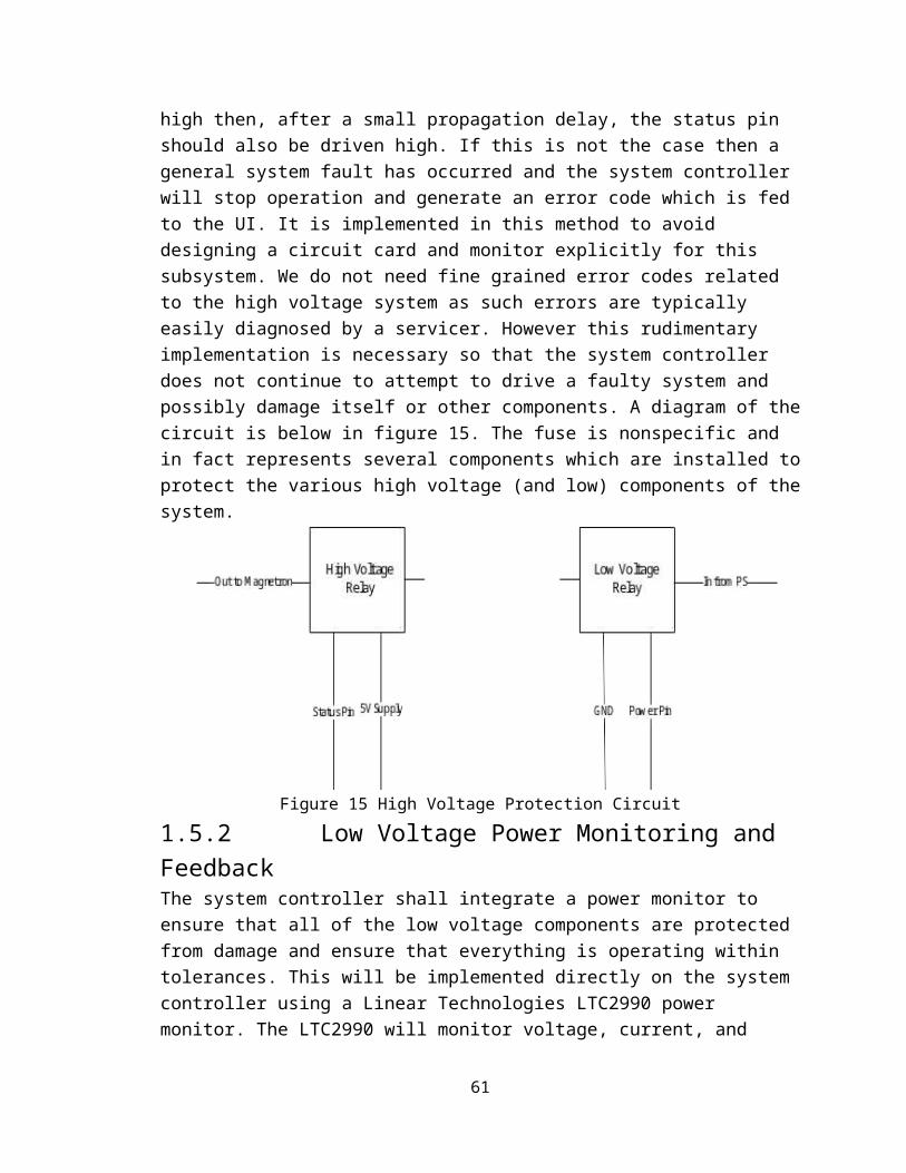
Figure 24– General Housing Design Concept
5.2.1 Why a Recessed Camera?The camera will be recessed 2.0 cm due to the 120.0 cm wavelength of the magnetic field produced by the magnetron. Since the camera lens of most commercially available CMOS cameras are 1.2 – 2.0 cm in diameter, it’ll be unlikely for the microwaves to enter the camera housing.Thought experiment: Think of trying to get a wave-shaped object that is sixty times larger than the diameter and length of a tube through. If the “height” of the object is relatively tall, it’ll be hard (or impossible) to pass the object through the tube. Microwave oven doors have holes roughly the same magnitude that work in a similar manner.
This technique of recessing the camera has been previously proven.
5.2.2 Housing CoverThe chamber cover will be made of quartz glass, recessed into the ceiling of the heating chamber, and tightly sealed. Quartz glass is a common surface used in cooking equipment such as electric conduction ovens, toasters and cooking ware. Quartz glass is used in cooking due to its non-stick surface, zero discoloration of material due to high temperature, highly flexible, low porosity (with respect to average food particles), great thermal insulation properties, resistance to crackage, low cost, very rugged and user friendly.
62

5.2.3 Housing BodyThe camera housing body will most likely be made of aluminum sheet metal and painted matte black inside the housing tunnel to minimize light reflection and overall image distortion. As an upshot, the matte black paint will also make image recognition an easier and quicker process; the embedded processor that is operating the image recognition software will be programmed to ignore certain pixel values because they will be null information. There are currently no specific mounting designs and will be done through trial-and-error.
5.3 Optics & LensesThe image recognition software depends on having consistent image quality and lack of distortion to work properly. There cannot be much “image-bending” due to having a wide capture angle, nor loss of focus due to changing subject distance with respect to the individual pixel sensor. The lens of the camera module is not adjustable, thus finding an appropriate lens is important. The figure below displays the optics system. The green and red lines show the ‘image paths’. The light pink line is the 'line of sight'. All illustrations used will use a perfect thin lens model (curvature on both sides are the same and no distortion due to lens thickness).
Figure 25 Perfect thin lens model
In the figure above lens 1 (top) has a greater aperture than lens 2 (bottom) (A1 > A2). Upon visual inspection, one can see that the angle of elevation (in orange) for A1 (φ1) is less than the angle of elevation for A2 (φ2). The optimal angle of elevation for sharpness of an image would be 90⁰. Since φ1 < φ2 < 90⁰, the bottom lens would create a sharper picture, especially on the outer edges of the captured image. In photographic quality, the top lens would create more 'vignetting' than the bottom lens. Lens 2 will have greater 'magnification power' than lens 1 due to lack of vignetting, thus a similar design is used in microscopes.
63

5.3.1 ApertureAperture describes the length/diameter of which limits the amount of light to be received and is a big factor in how “straight” the light hits the pixel sensor; the straighter the light, the shaper the picture.
Figure 26 Aperture
5.3.2 Focal LengthFocal length is the distance from the lens to the point where all light converges towards the pixel sensor.
Figure 27 Focal Length
Focal length can affect the magnification of a perceived object in the pixel sensor.
Figure 27 shows three different object points (p1, p2, p3) with respect to the center of the lens (S). Since we're using a perfect thin lens model the object distances are the same as the focal points (f1, f2, f3). In most camera lenses, the focal points are much shorter than the object points. Since p3 < p1 < p2 then f3 < f1 < f2. The pixel sensor can only detect light hitting it. The image from p1 is optimally in focus and full resolution/full-size of the object with some vignetting. The image from p2 will appear smaller than p1, have lower resolution/magnification and the least amount of vignetting. The image from p3 will have the highest
64

resolution/magnification at the cost of not all of the object being in the picture and will have the greatest vignetting.
5.3.3 Circle of ConfusionIn optics, all object points that are not in focus become stretched and distorted. The circle of confusion (COC) is defined as the magnification of single point that is no longer identifiable. In the human eye, the COC mainly depends upon the cone and rod surface density in the optic nerve. The higher the density, the smaller the circle of confusion, thus finer focusing is required to pick up the details of point-like object in space. CMOS sensors work in a similar fashion.
Figure 5.6.a shows three neighboring pixel sensors within the optic sensor. The COC occurs when a point-like object's image spread is larger than what is perceivable for the center pixel sensor. The diameter of the circle of confusion is labeled D, which is basically the smallest length of the pixel sensor. In older film cameras the COC was determined by the grain size of the effective photo reactive molecules.
5.3.4 Depth of FieldDepth of field (DOF) describes the difference in the range of distances in which an image is focused and visible. DOF is effected mainly by aperture and COC of an optical system and is essential for clear imaging. In figure 5.3.2.1, the DOF of the figure would be distance from the pixel sensor to f2. If the aperture of the lens was less than the pixel width, the DOF would be infinite.
5.3.5 Viewing AngleLens distortion and shading can occur due to using a wide viewing angle. From experience as filming skateboaring with a wide angle lens (fisheye lens in skater lingo), the wide angle lense will stretch or thin-out the light on the outer edges of the optical sensor, specifically the outer pixel sensors on the total optical sensor package, causing the colors to seem darker on the outer edges. Many photographers and videographers mistake this extra vignetting being caused by a high aperture while using a wide-angle lens, yet this distortion cannot be corrected without changing to a smaller angle lens or sophisticated and professional editing software such as Adobe Photoshop, Darkroom Pro or Corel PhotoPro. Due to the hardware, functional, and cost restrictions we cannot employ the use of such software, thus it is important to use a minimal viewing angle lens. Unfortunately many CMOS camera module packages have wide angle or straight angle lenses, so we may have to purchase, properly mount and allign, and secure said lens. This can be difficult to novice optical systems engineers.
65

A viewing angle of between 30 and 60 degrees should be sufficient for the NOMS optical system. We'd like to have as minimum of a viewing angle to decrease lens distortion.
5.4 CMOS Camera OperationFor simplicity and cost reduction, we will be using a black and white CMOS camera. CMOS cameras are small, cheap, and come in a large variety of designed uses and needs. We will be using a black and white CMOS camera to keep the possible value range of each pixel to 256 shades of grey, rather than 16,777,216 possible values for red-green-blue (RGB) pixels. This is speed up the performance time and lower complexity for quick response (QR) code recognition.
5.4.1 Light-To-Charge ConversionWhen selecting a CMOS camera, the first consideration is the size or area of each pixel sensor. The larger the pixel sensor, the more light it can capture into the photo detector, and thus the lower lighting the sensor can read from. Smaller pixel sensors are less expensive to produce due to simpler and smaller optics. The light/photons that enter the microlens, pass through the color layer detector, and deposit some energy onto the photodetector, due to the photoelectric effect. If the photon strikes an electron within a material, with enough force to overcome the work function of the material, the electron will have energy higher than the Fermi level, and thus become a free electron. These free accumulate on a capacitor to produce a voltage. This measured voltage (pixel voltage) will be amplified, compared, and converted to digital code. Then the capacitor is discharged and the process happens again.
5.4.2 Lighting ConditionsUntil recently CMOS cameras were considered to have optimal image quality outside on a bright day, where the light is intense and the wavelengths evenly spread out. Currently there are low-light sensitive CMOS cameras but their price and applications do not math out needs. We will need to add a bright bulb inside the heating chamber to properly illuminate the QR code on the food. The placement of the bulb is key to minimize reflectance into the camera, to insure a clear picture for the QR code software.
5.4.3 Pixel Dimension Optimization (PDO)There are three main factors that limit the dimensions of the image sensor; the average highest rated clock speed of each pixel sensor (referred to as “clock-out time), the sum of all pixel clock-out times (referred to as “shutter time”), and the speed of the processing hardware.
66

5.4.4 Clock-Out & Shutter TimeClock-out time is the average time it takes to read the voltage across each pixel capacitor and then discharge the capacitor. Luckily, using CMOS technology significantly shortened the clock-out time compared to previous technologies such as a charge-coupled device (CCD), though pixel density has decreased a bit. Clock-out time is the biggest factor in PDO. If the light is bright and clock-out time shortened, this will cause the greatest speed changes in the camera memory system. Most CMOS camera sensors have pins to assign the clock speed, some have fixed internal clocks.
Shutter time is the average time is takes to read and store all of the pixel voltages; i.e. approximately the sum of all pixel clock-out times. The larger the dimensions; the longer the shutter time. The shutter time and memory read/buffer clock should be the same. If the shutter time and memory read clock are just a bit off you will have aliasing of the image in the form of image compression or expansion (similar to adjusting the tracking on an old analog TV). A buffer can be built using an FPGA.
5.5 Image Quality Control:Contrast ratio:The contrast ratio is inversely related to the difference in bright and dark pixel values. For instance, NOMS will use 256 pixel values from 0 to 255, where 0 is absolute darkness (black) and 255 is absolte brightness (white). The ontrast ratio range would be 0 to 0.9961. An Analog-to-digital converter would be optimal to create a digitized contrast ratio output from the image sensor.
Luminosity describes the relative brightness of each pixel in an image. Generally below in eq(name) where Vout is the luminosity, A is the brightness gain, and the exponent is the gamma-correction factor, and Vin is the contrast ratio.
The values of reference voltage is [0 - 255], thus Vin = [0 0.9961]. When the reference voltage is 0, the pixel value is completely black When the reference voltage is (about sign)1, the pixel value is completely white. When reference voltage is 0.5, the pixel value is a 'neutral gray' (aka equally hued).
gamma correction;Gamma correction cause non-linear relative hueing of the individual pizel values. Below is a table discussing the extreme changes to brightness' with respect to gamma and Vin:
67
Gamma = 1, A = 1:Pixel Color: Pixel value: Vin Vout Character:
Black 0 0 0 Same
Dark Gray 64 0.25 0.25 Same
Medium Gray
128 0.5 1 Same
Light Gray 192 0.75 0.75 Same
White 255 0.99 0.99 SameTable 17 Gamma 1 Values
Nothing about the image has changed here. The hue and gray saturations have remained the same.Gamma = 1.5, A = 1:
Pixel Color: Pixel value: Vin Vout Character:
Black 0 0 0 Same
Dark Gray 64 0.25 0.13 48% darker
Medium Gray
128 0.5 0.35 30% darker
Light Gray 192 0.75 0.65 13.3% darker
White 255 0.99 0.99 sameTable 18 Gamma 1.5 Values
When gamma is increased, the darker values become much darker and the lighter colors only darken a small amount. Thus the image will lose detail in the darker areas of the image but greater detail in the lighter ares of the image.
Gamma = 0.5, A = 1:Pixel Color: Pixel value: Vin Vout Character:
Black 0 0 0 Same
Dark Gray 64 0.25 0.5 100% Lighter
Medium Gray
128 0.5 0.71 42% lighter
Light Gray 192 0.75 0.87 12% lighter
White 255 0.99 0.99 SameTable 19 Gamma 0.5 Values
68

When gamma is decreased, the darker values become much lighter and the lighter values only lighten a small amount. Thus the image will lose detail in the lighter areas of the image but greater detail in the darker areas of the image.
For the NOMS system, we would rather have contrast over detail. The identifying software only needs to know the difference between light and dark. Thus a gamma value greater than one would be optimal.
Figure 28 Gamma-Corrected Contrast Ratios
This figure is of the Gamma-Corrected Contrast (GCC). For the figure, gamma < 1 (blue), gamma = 1 (green), gamma > 1 (red). The seperation of gamma is 0.1.
5.5.1 Black & White Value Optimization
To further increase the performance of the QR code recognition software, we’re going to place a comparator inside the buffer that’ll shorten the amount of pixel possibilities from 256 values down to 32, 16, or 8 values. We will try out all possible logic combinations under different lighting and color effects to find the best/robust solution. Hopefully we’ll find a consistent value to use.
5.5.2 Value BinningBinning is the classic statistical method of place ranges of values within specified groups known as bins. If one uses gamma correction followed by binning one can shift or skew the population of darker (or lighter) bins from being linear to non-linear, thus increasing the yield of either darker or lighter values. Below is a
69

few detailed examples over the whole possibilities for monochrome-coded values. The next three examples illustrate the three conditions with even binning of eight, meaning;
If Vout < 32, then Vout = 0; Bin1.If 32 <= Vout < 64, then Vout = 32; Bin2.If 64 <= Vout < 96, then Vout = 64; Bin3.If 96 <= Vout < 128, then Vout = 96; Bin4.If 128 <= Vout < 160, then Vout = 128; Bin5.If 160 <= Vout < 192, then Vout = 160; Bin6.If 192 <= Vout < 224, then Vout = 192; Bin7.If 224 <= Vout < 256, then Vout = 224; Bin8.
1. Gamma = unity
Figure 29 Gamma Unity
Binned Color / Pixel Value: Percentage of Pixel Population:
Black / 0 12.50%
Dark Dark Gray / 32 12.50%
Dark Gray / 64 12.50%
Dark Light Gray / 96 12.50%
Neutral Gray / 128 12.50%
Light Dark Gray / 160 12.50%
Light Gray / 192 12.50%
70

Light Light Gray / 224 12.50%Table 20 Gamma Unity Values
Since gamma = 1, there is no skewness and linearity is maintained. Thus, you'll get an even distribution of all "lower colors" after binning.2. Gamma > 1
Figure 30 Gamma 1.5Binned Color / Pixel Value: Percentage of Pixel Population:
Black / 0 25.00%
Dark Dark Gray / 32 14.84%
Dark Gray / 64 12.11%
Dark Light Gray / 96 11.33%
Neutral Gray / 128 9.77%
Light Dark Gray / 160 9.77%
Light Gray / 192 8.59%
Light Light Gray / 224 8.59%Table 21 Gamma 1.5 Values
Since gamma = 1.5, there is a positive skewness on the lower pixel values (darker shades) and negative skewness on the upper pixel values (lighter
71

shades). Overall, the dark values become darker and greater in population, the lighter values also become darker yet less in population.
72

3. Gamma < 1
Figure 31 Gamma 0.5
Since gamma = 0.5, there is a negative skewness on the lower pixel values (darker shades) and positive skewness on the upper pixel values (lighter shades). Overall, the dark values become darker and smaller in population, the lighter values also become darker yet higher in population.
Binned Color / Pixel Value: Percentage of Pixel Population:
Black / 0 1.95%
Dark Dark Gray / 32 4.69%
Dark Gray / 64 7.81%
Dark Light Gray / 96 10.94%
Neutral Gray / 128 14.06%
Light Dark Gray / 160 17.19%
Light Gray / 192 20.31%
Light Light Gray / 224 23.05%Table 22 Gamma 0.5 Values
73

5.5.3 Image SharpnessDue to the gamma-correction followed by the pixel values, the image should be have sharper edging and greater contrast between darker and lighter pixel values. This will further ease the ability of the QR code recognition software. The gamma value will depend on the lighting conditions within the heating chamber and binning values (previously used was a binning value of eight) will also decrease image distortion due to reflected and refracted light from the quartz camera shielding and the material the QR code is printed on.
Design considerations:1. Use a light meter in the heating chamber to determine the gamma value through some loop feedback system. 2. Tinker and toy with gamma and bin values till an overall sharpness can be maintained over a range of QR code sizes and positions. 3. Further reseach in sharpness and contrast adjusting.
5.6 Quantifying Sharpness and monochrome-Valued Optimatization
Attempting to increase the sharpness and contrast qualities of monochrome-valued images is worthless unless one can measure the effectiveness and sensitivities of each variable change to the overall optics system. The following has many methods to deteremine how effective each variable (gamma, binning, apeture, and focal length) change can be and which ones are significant factors in image correction/distortion.
5.6.1 Measuring Effectiveness of Focus & Lens SystemAs previously mentioned, for a simple CMOS camera system, the aperture and focal length are the dominant factors in maintaining a focused image. Below is a method to find the best focus area of an imaging system.
1) Edge Spread FunctionThe edge sread function (ESF) determines how much variance in shading from a true edge and outwards the pixel values change. First, take a true edge or use a fine split, and place it in where an object would normally be in the image capturing area and record an image. With this edge test image, sample different area along the true edge area portions. Test areas of sharpest edge quality and areas of dull or unfocused edge qualities. The ESF is simply the normalized pixel values in a given test area of the image. Areas of greater standard deviation offer the sharpest edging, and areas of lesser standard deviation offer more out-of-focus edging.
74

ESF= X−µσ ,where σ=√∑i=0
n−1
(x i−µ)2
nX = The input array of pixel intensity
µ = The average value of the pixel intensity dataσ = the standard deviation of the pixel intensity
n = number of pixels used in average
2) Line Spread FunctionThe line sprerad function (LSF) is derived from the ESF and is used to determine how sharp an edge of a line is on an image from a given pixel in the sample area. This is simply the change of the LSF over distansce (the space derrivate of the ESF). The greater the change of the ESF from the given pixel, the sharper the edge created. Since ESF is determined numerically, the LSF is determined using numerical approximations. Thus the following equation satisfies the LSF within reasonable values:
LSF= ddx
ESF ( x )
Line-Spread
LSF≈ESFi+1−ESFi−1
2( xi+1−x i)Line Spread Function Approximation
3) Modulation Transfer FunctionNow that we found the area with the least line spread (LSF), using a discrete Fourier transform (DFT) one can determine where focus is the greatest with respect to a single pixel, this is the modulation transfer function (MTF). The reason for the DFT of the LSF is one can evaluate how frequently pixel values change from a given pixel.
MTF=DFT [LSF ]Modulation Transfer Function
MTF=∑n=0
N−1
yn e−ik 2πN n
Where, yn = nth pixel positionN = number of data points
N = index
75

As a rule of thumb, values between 0.4 and 0.6 have the best focus in the sampled area.5.7 Video Format QualitiesThere are many forms of video and image transmission methods. There are many options. pros, and cons on all transmission methods. Before we explore the differences in video transmission formats, we need to discuss the common qualities that all methods share.
1. Frame RateSimply put, frame rate describes how many still images are presented within a second. Frame rate is generally measured in frames per second (fps) or represented as a frequency (number of events per second). Frame rate allows the user to experience the sensation of motion. The human eye can see about 10 to 12 frames per second, thus a frequency range of 10 to 12 hertz. (http://en.wikipedia.org/wiki/Frame_rate ). The human eye and optical cortex does not see in "frames" but rather a continuous blurring between moments of optical input, meaning optical cortex has a correction feature for the slow frame rate. This built in blurring feature allows us to perceive and interact with fast moving objects; most likely an adaptation to avoid dangerous situations such as being able to focus on objects while falling, thrown objects, and fast predatory animals. Because of this feature, the human eye can detect differences in presented frame rates in the range of 30 to 45 fps, but this is dependent on other factors such as color contrast, light levels, and the distance of the moving object from the viewer.
For conditions needed in monitors and television an accepted rule of thumb for minimal frame rate of effective motion is 16 fps (http://en.wikipedia.org/wiki/Persistence_of_vision ), this is commonly referred as the Rate of Confusion. Any rate higher than the Rate of Confusion is acceptable for sensed motion without effects like flicker, flashing, and choppy movement. Modern cinemas and NTSC has frame rates of 24 fps while modern high-definition television and video gaming has frame rates of 60 fps. It is said that there is no reason to have higher frame rates, because it'll not increase the fluidity, qualities, and sensation of motion.
2. Line & Pixel ScanningUnfortunately a computer or television can only change one pixel or line at a time. At the moment the only method of presenting an image is with line/pixel scanning. Fortunately we're going to be working with a digital transmission and since the microprocessor is the 'viewer', distortion of the frames is not a factor. Microprocessors are not picky and I'm certain do not experience flickering and distortion due to line and pixel scanning.3. Aspect Ratio
76

Since the end-user in many optics systems are human, the aspect ratio is generally defined about aesthetic and appearance, but is an important consideration for the NOMS optics system and image processing time. Most video imaging systems use a rectangular display form, with exception to radar and some faux holographic systems. Aspect ratio describes the width in terms of a normalized height of the viewing area. Historically aspect ratios have been more "boxy" such as analog television and early cinema, thus the aspect ratios are closer to 1.example: square image -- 1:1
traditional television -- 4:335mm photography -- 3:2IMAX -- 1.44:1common computer screen -- 1.6:1Super 16mm film -- 5:3U.S. digital television -- 16:9widescreen cinema -- 2.4:1
The reason we want to restrict the aspect ratio as much as possible with NOMS is to decrease the amount of processing time for the QR code recognition software. The camera will be mounted within the heating chamber directly centered above the microwave turntable. The effective aspect ratio should be as close to a square image (1:1) as possible since the heating chamber's dimensions are restricted by it's depth (from the oven door to the back of the heating chamber). The software can also ignore lines of the image due to insufficient focus, image distortion, or lens shading. This will be determined during the building of NOMS. 4. Graphics ResolutionOnce an appropriate aspect ratio is determined, the next important consideration in decreasing the image processing time is the graphics resolution. Resolution describes how many separate pixels are used to project an image. Generally, the higher the pixel density, the sharper a digital image appears. In analog video imaging, resolution is dependent on optics, lighting, internal system noise and transmission, and the continuous nature of analog video means the idea of pixels is meaningless.
Another consideration when choosing an appropriate pixel resolution is that the greater the pixel resolution, the clock-in times are faster, larger buffers are required, faster (and generally more expensive) image processing is needed. But with larger pixel resolution comes greater image sharpness and clarity. Below is a table of some common aspect ratios and their different pixel resolutions:
77

Aspect Ratio: Pixel Resolution :(horizontal x vertical)
Megapixels: (MP)
Graphics Array Type:
16:9 // 1.78:1 432 x 240 0.1037 FWQVGA
640 x 360 0.2304 nHD
960 x 540 0.5184 qHD
1280 x 720 0.9216 HD/WXGA
1600 x 900 1.4400 HD+
7680 x 4320 33.1776 UHD
5:3 // 1.67:1 400 x 240 0.0960 WQVGA
1280 x 800 1.0240 WXGA
3:2 // 1.5:1 240 x 160 0.0384 HQVGA
480 x 320 0.1536 HVGA
1440 x 960 1.3824 WSXGA
4:3 // 1.33:1 160x120 0.0192 QQVGA
640 x 480 0.3072 VGA
800 x 600 0.4800 SVGA
1024 x 768 0.7864 XGA
1152 x 864 0.9953 XGA+
2048 x 1536 3.1457 QXGA
6400 x 4800 30.7200 HUXGA
5:4 // 1.25:1 1280 x 1024 1.3107 SXGA
2560 x 2428 5.2429 QSXGA
5120 x 4096 20.9715 HSXGATable 23 Common Resolutions for Aspect Ratios
Due to the wide availability of compatible electronics, systems, and convenience it's speculated that the VGA resolution would be adequate for the NOMS optical system. CMOS VGA camera modules are common, cost effective, reliable, very flexible, vast cross-compliance, and comes with an large choice in lenses. Also we believe that the microprocessor will be able to easily handle the 0.307 MP size of each image.
78

5.7.1 Video Graphics Array Camera Operation
Besides the aspect ratio and pixel resolution being standard for video graphics array (VGA), since it is a long-used and well-developed video format, there are other expected (or industry standard) maximum and minimum properties.
With respect to the image buffer, maximum frame rate for VGA is generally 70 fps for a 14.29 millisecond shutter time, and an average clock-in time of 40 nanoseconds or 25 MHz. 60 fps is a common frame rate for a 16.67 millisecond shutter time, and an average clock-in time of 50 nanoseconds or 20 MHz. The slowest acceptable frame rate is 30 fps for a 33,33 millisecond shutter time, and an average clock-in time of 100 nanoseconds or 10 MHz. It is important that the lower the frame rate, the more accurate the clock-in determining clock must be. Most software and hardware compliance works with 60 fps, though some are adjustable.
As the name suggests the pixel values for monochrome operation of the camera are stored and delivered as an array, where each element of the array can take up 8-bits (256 grayscale possibilities), 6-bits (64 grayscale possibilities), and 4-bits (16 grayscale possibilities), and each array represents a full horizontal line. For coding simplicity and convenience of working in hex, the 8-bit or 4-bit elements would be the preferred choice. Though there is a rather large difference in contrast and clarity between using 8-bit versus 4-bit monochromatic values, being that 8-bit would have greater clarity with 4-bit would have greater contrast. During the building of NOMS we'll experiment with 8-bit and 4-bit pixel values, with preference towards 4-bit monochromatic values due to simplicity and faster processing time.
Due to the aspect ratio and pixel resolution, VGA does have reduced resolution than other more-modern resolution standards, such as qHD and XGA. Though, the goal of the optics system is to identify QR codes and not image quality, thus the resolution needs to do the job and not be aesthetic for human viewing pleasure.
Most VGA CMOS cameras have an operating voltage of 0.7 volts at 75 ohm and 18.7 mA, and at half-duty, thus the power consumption is roughly 13 mW. This is an engineering standard so that buffer design and transmission of signal is uniform across all VGA CMOS cameras. This is a great convenience since many other video resolution formats for CMOS devices are usually specific to the manufacturer, and thus limits the availability of compatible parts and raises the cost of the parts.
79

5.7.2 VGA Line Data Transmission Details
The following describes the transmission of one horizontal line from a VGA image.
Parameter: Value:
Front Porch (A) 0.94 us
Sync Pulse (B) 3.77 us
Back Porch © 1.89 us
Active Video (D) 25.17 us
Total Line Time 31.77 us
Table 24 VGA Line Data
This transmission protocol is for the standard VGA frame rate, 60 fps. Part A of Table 24 is a short pause signal, called the front porch, that is active high for 0.94 microseconds. Part B is called the sync pulse, its purpose is communicate to the visual hardware that a new line is occurring. The sync pulse length is 3.77 microseconds. Part C compliments part A, and so it's name is complimentary too, the back porch. As you might have guessed the back porch is also a short pause signal with a length of 1.89 micro seconds. Part D is called the active video signal and carries the 640 horizontal pixels for the line, and the duration is 25.17 microseconds. Since 640 pixels are being distributed in 25.17 seconds, the pixel frequency is 25.427 MHz. The total time for each line delivered is 31.77 microseconds, thus it would take a total of 15.250 milliseconds to deliver one full frame. Just to check, that comes out to 65 fps, which is close enough for now. Below is a table to summarize VGA line data transmission.
80

5.8 CMOS VGA Camera Features 5.8.1 Color FlexibilityA large portion of cheaper CMOS VGA cameras available on the market usually provide monochromatic, grayscale, and RGB, and are fully programmable for whatever color scheme you desire. We'll most likely be using grayscale for greater simplicity.
5.8.2 60 Hz EliminationIn North America, the power mains run at 110 volts and 60 Hz, unfortunately VGA also runs at 60 Hz, so it can detect the flickering of lighting equipment that the human eye cannot see. Most modern CMOS VGA camera modules come with a 60 Hz flashing filter to keep annoyances such as irregular lightness/darkness or flickering to occur due to aliasing.
5.8.3 White BalanceAgain, a very common (nearly unavoidable) feature found in CMOS VGA camera modules is the automatic white balance feature. Pretty much, within the pre-buffer there will be a correction factor on the lightest pixel so that it's value is 255 (pure white), and linearly raise every other pixel by the same difference. There are non-linear and more sophisticated white balance features, but only found in upper end laboratory and photography equipment, which is out of our price range.
5.8.4 Anti-BloomingAn important consideration in choosing a CMOS camera module is an anti-blooming feature. Anti-blooming technology maintains the same mean individual pixel area on the image sensor, yet decreases the area of the pixel sensor, thus a buffer is created for electrons to leak from one pixel sensor to the other. The total effect of blooming is streaking of the image where there is intense light. The upshot is that intense points of light on the image does not create blind spots in the image (ie, cause hyperactivity to nearby pixel sensors), yet light sensitivity is decreased (in which CMOS camera sensors are already less effective at light sensitivity than CCD technology).Advantages:
-- Reduces glare and intense points of light.-- Increases overall image sharpness in outdoor and high-level indoor lighting.-- Greater pixel contrast. -- Flexible in well-lit areas.
Disadvantages:-- Reduced light sensitivity of each pixel sensor. -- Longer shutter time leads to sensitivity of blurring with motion.-- Greater cost.-- May not be necessary
81

5.8.5 I2C CompatibilityI2C (Inter-Integrate Circuit) is a very common and easy to use master/slave protocol for the camera to communicate with other peripherals. I2C runs on 7-bit addressing, just as VGA standards are, thus grabbing and storing data between two separate parts will be very easy.
Advantages:-- Reduces glare and intense points of light.-- Increases overall image sharpness in outdoor and high-level indoor lighting.-- Greater pixel contrast. -- Flexible in well-lit areas.
Disadvantages:-- Reduced light sensitity of each pixel sensor. -- Longer shutter time leads to sensitivity of blurring with motion.-- Greater cost.-- May not be necessary
5.8.6 Operating System SupportLuckily VGA was a dominating graphics format in the late eighties and early nineties and still hasn’t died out, so most operating systems have built-in VGA support. Experimenting and tinkering will be easier with the vast operating system support that VGA has to offer.
5.8.7 Cost-EffectivenessBesides state-of-the-art laboratory and slow-motion cameras, almost all CMOS VGA camera modules with the above features are less than $20 U.S. This is very inciting for us poor college folk.
5.8.8 Lens OptionsMost cameras you can order have a wide choices in lenses, that have different focal points and apertures to suit your needs.
82

UPC Codes6.1 Motivation for UseEstablished in 1973, Universal Product Codes, hereafter referred to as UPCs, have become a near universal for identifying trade items. They provide a simple system for retailers to inventory and sell. While not ideal for our purposes they provide a usable point of data that allows us to achieve our goal of automatically cooking. They are fairly limited in the amount of data that can be encoded which means that their use requires additional support systems to use them in the microwave. Despite this limitation we have decided to implement their use because the system is already in place.
6.2 UPC StandardsThe governing body which established and maintains the standards regulating the use and implementation of UPCs is GS1. The relevant specifications are detailed in the GS1 general Specifications document which can be obtained from [33]:http://www.gs1.org/docs/gsmp/barcodes/GS1_General_Specifications.pdf
The most common standard in use is UPC-A which is 12 digit system of trade identification. It has been superseded by the European Article Number, hereafter referred to as EAN, and is a subset of this standard. The EAN13 specification adds a thirteenth digit to the code. UPC-A can be converted to EAN13 by simply appending a 0 to the front of the code. For this reason we will restrict our discussion to the EAN13 specification.
6.3 EAN-13 Specification and CompositionA fairly detailed discussion of how the EAN-13 barcode is implemented will be necessary as we will have to implement systems capable of capturing and decoding these codes in order to identify what is to be cooked.
Figure 32 EAN-13 Symbology
83
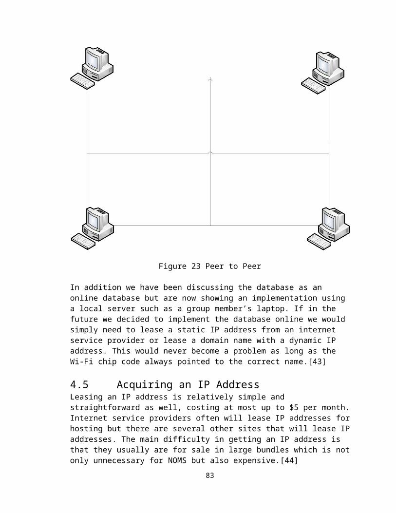
The EAN-13 specification encodes a Global Trade Item Number or GTIN which uniquely identifies the item being scanned. The GTIN-13 is composed of three parts; the GS1 company prefix, item reference, and check digit. The company prefix is issued by the GS1 Member Organization of which the company is a part. This portion is important for our purposes, aside from product identification, in that it allows us to identify the manufacturer for advertising and product tracking. The item reference identifies the individual product. Finally the check digit is used for error correction. This code will be relayed to the database subsystem by the SoC.
The physical composition of the EAN-13 barcode is our primary concern. It consists of:
A left Quiet Zone A normal Guard Bar Pattern Six symbol characters from number sets A and B A center Guard Bar pattern Six symbol characters from number set C A normal Guard Bar Pattern A right Quiet Zone
Figure 33 EAN-13 Composition
84

Symbol characters are encoded in three different sets known as A, B, and C as given in Table 25.
DigitValue
Set A element Widths Set B Element Widths Set C Element Widths
S B S B S B S B S B S B0 3 2 1 1 1 1 2 3 3 2 1 11 2 2 2 1 1 2 2 2 2 2 2 12 2 1 2 2 2 2 1 2 2 1 2 23 1 4 1 1 1 1 4 1 1 4 1 14 1 1 3 2 2 3 1 1 1 1 3 25 1 2 3 1 1 3 2 1 1 2 3 16 1 1 1 4 4 1 1 1 1 1 1 47 1 3 1 2 2 1 3 1 1 3 1 28 1 2 1 3 3 1 2 1 1 2 1 39 3 1 1 2 2 1 1 3 3 1 1 2
Table 25 Number Sets A, B, and C
Since the EAN-13 Bar code consists of only 12 symbols the thirteenth digit (leftmost) is encoded by the variable parity mix of the first six symbols as given in Table 26.
EncodedDigit
Number Sets Used of Numbering Left half of an EAN-13 Bar Code
1 2 3 4 5 60 A A A A A A1 A A B A B B2 A A B B A B3 A A B B B A4 A B A A B B5 A B B A A B6 A B B B A A7 A B A B A B8 A B A B B A9 A B B A B A
Table 26 – Implicit Digit Encoding
85

UPC CaptureTwo basic methods exist for the physical capture of the barcode. The simplest and most common method is laser scanning. They are very well suited to scanning EAN-13 barcodes but lack the flexibility to read 2D codes (such as QR). If we choose to use this method there are several off-the-shelf solutions suitable for our purposes however these can be cost prohibitive. The second method is digital imaging. All that is ultimately needed is a simple, inexpensive, CMOS camera. This method offers the flexibility to capture 2D codes and is the primary method which we will explore for capturing our barcodes. The significant disadvantage associated with this method is the necessity of processing the image so that it can be decoded.
6.4.1 Grayscale ConversionThe image captured by the camera will be relayed back to the SoC. At this point some post-processing will be necessary to make it possible to decode the UPC. The first step we will use is Grayscale conversion of the image. Since the barcode is, by definition, black and white we can remove a lot of “noise” from the image simply by performing this conversion. The format of the data packet will ultimately depend on the specific camera that we end up using, but regardless of the format it will eventually be converted into a simple 2d array where each pixel is represented by three 32-bit values for red, green, and blue intensity. Each of these will be converted to a single 32-bit grayscale value. Some experimentation will need to take place to determine the best method for our application but three basic algorithms exist for performing this calculation.Lightness method:
P=(max (R ,G ,B )+min (R ,G ,B))/2Average method:
P=(R+G+B)/3Lumosity method:
P=0.21R+0.71G+0.07 BIt is highly likely that the individual algorithms above will produce similarly useful results for our application and so the simplest average method will likely be applied.
86

6.4.2 FilterWith the image converted to grayscale we can further refine our image by filtering pixels which are not black or white. The specific thresholds we will use will be subject to experimentation but the essential idea is that pixels which do not lie at the extreme ends, black or white, can be filtered from the image leaving primarily the barcode.
6.4.3 Black and White ConversionThere is no longer any reason to maintain any grayscale information and all pixels will be converted to a simple black and white representation. This is done primarily to simplify the final 2 steps.
6.4.4 DeskewIt is now advantageous to correct any image skew that may be present to make it simple to decode the UPC. This is done by detecting the lines in the image using a Hough transform, calculating the slope of those lines, calculating the average skew, and rotating the image. This is the most processor intensive part of the process requiring a great deal of floating point math and will likely be critical algorithm which determines the necessary computational power of our SoC. However, today’s processors are generally much more powerful than is strictly necessary for performing their task and the SoCs which are under consideration are all well suited to the task.
6.4.5 CropBlank, or nearly blank, lines can now be eliminated from the image entirely leaving only the UPC for processing.
6.4.6 UPC DecodingWith the image deskewed and cropped it is now fairly straightforward to decode the image. Basic edge detection techniques allow us to detect the guard bar patterns and determine the thickness of the various bars and spaces. The GS1 specification provides a basic algorithm for decoding the UPC and it will be used as a starting point for our system. It is presented in section 5.2.2 of the specification document.
6.4.7 Check DigitOne final consideration that has not been addressed up until this point is data validation. The final symbol in the barcode is the check digit. It is used to validate the decoded GTIN-13. It is given by the following formula:
N 13=[N1+N3+N 5+N7+N 9+N11+3 (N2+N 4+N6+N 8+N10+N12 ) ]%10
87

6.5 Programming ConsiderationsWhile a good deal of code will have to be developed, the algorithms for performing many of these tasks are well established. There are a couple of C libraries specifically created recognizing and decoding UPC codes. Specifically the open source Zbar (http://zbar.sourceforge.net/) libraries will be evaluated for use in our project.
88
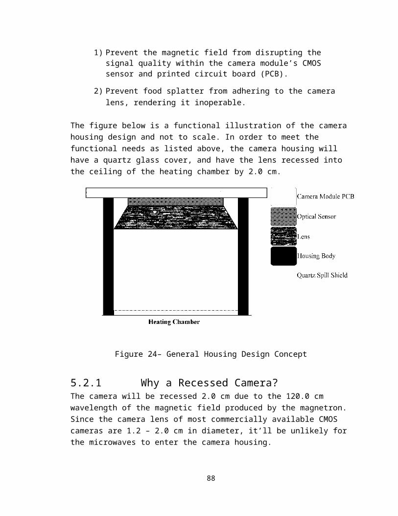
QR Codes7.1 Motivation for UseQR Codes are a 2D standard which is able to convey much more information than a simple UPC. We intend to use these codes to deliver cooking instructions directly to the microwave system without the necessity of accessing a database. The advantages are offset partially however by the relative complexity of capturing and decoding them. A laser scanning system is not sufficient and a digitizer will be required. Their inclusion in the system is not finalized and further testing and evaluation will be necessary to determine both feasibility and efficacy.
7.2 QR StandardThe QR code system was originally invented by Toyota for vehicle tracking during manufacturing but its use has expanded well beyond that limited function. Today QR codes can be found nearly everywhere, from POS systems, to advertising, and even as login credentials. While GS1 manages its own QR based standard, it is not particularly useful for our purposes. The specifics regarding QR and its use in retail ultimately does not pertain to the specific of encoding and decoding data in this format. Instead we will draw our information from the ISO/IEC 18004:2006 specification. It can be found at [34]:http://webstore.ansi.org/RecordDetail.aspx?sku=BS+ISO%2FIEC+18004%3A2006
7.3 QR SpecificationWhile all QR codes share several features, their specific implementation can vary significantly depending on the specific type of code. There are forty different QR code types mostly differing in the amount of data which can be stored. The most common format is version 2 which can encode, at a medium level of error correction 224 bits of data. This will allow for 14, 16-bit fields, which is sufficient for our needs and will be the QR code implemented.
7.4 QR CompositionQR codes are complex and integrate several advanced features over UPC. The QR incorporates various features which allows the code to be more easily captured and be more tolerant of damage and image distortion. These include multiple levels of error correction as well as data masking to distribute the data across the code area. Some important features of the QR structure and layout are shown below in Figures 34 and 35.
89

Figure 34 QR Code Sturcture
Figure 35 QR Code Layout
90

7.5 QR GenerationThe specifics of generating a QR code are not important for our application. There are several, freely available tools for creating QR codes encoded with whatever data you wish. I will restrict our discussion instead to the specific data fields and formatting that will be used. The first two fields will be identical to those found on the UPC. The first will be a 16-bit Integer which will contain the company prefix followed by another 16-bit Integer containing the item reference. The remaining fields will encode the various cooking times and temperatures with a flag for the turntable. The first 4 bits will encode the power level from 0-10. The next 11 bits will contain the number of seconds to operate at that power. This allows for approximately half an hour of operation at a given power. Should the unlikely situation arise that a longer cooking time is needed, a second field at the same power will extend that time. The final bit will flag whether or not the turntable is to operate. The chosen QR specification can encode 14 of these 16 bit fields. This allows us to have instruction sets for multiple wattages, 4 instructions for 3 wattages.
0 16Company PrefixItem Reference
Power Time Turntable Flag…
Table 27 Cook Data Format
7.6 QR Code CaptureThe 2D nature of QR symbology necessitates the use of digital imaging for their capture. The methods discussed previously in the capture of UPCs apply equally well to QR code capture. However additional care must be taken when choosing the camera, its position, and focus. The data is more compact in the QR code than the UPC and a higher fidelity source image must be obtained for reliable decoding of the information. This is somewhat mitigated by the various levels of error correction inherent in the QR standard. We will attempt to balance camera performance at a medium level of error correction.
7.7 QR DecodingCode level implementation of QR decoding algorithms is a complex task that would, in and of itself, represent a significant software design project. It is outside of the scope of this project and the use of QR codes in our application will rely heavily on the feasibility of using an existing open source library, namely the aforementioned Zbar C Library.
91

User Interface
When considering the design of the user interface it became immediately apparent that a simple push-button interface would not be sufficient for our needs. Migrating to a touchscreen LCD seemed to be the most efficient solution providing the necessary interactivity and feedback to meet our design goals. The user interface must provide the following functions:
Display the time while in standby Provide a method whereby either a UPC or QR code can be scanned Provide a method for manual cooking Provide a method for the system to be configured Provide a method to enter and maintain use profiles Provide a method for entering and maintaining custom cooking
instructions Display product and status information while cooking
These features should be implemented in an intuitive and dynamic way. The purpose of this system is to make the microwave experience simpler and more feature-rich. The home screen is simple and clean presenting very few options. The primary function of the microwave should be to scan a product. This option will be presented prominently on the screen to encourage the user to automatically select it. Optionally the home screen will allow access to manual cooking and settings. The design is below as figure 36.
Figure36 Home Screen
92

While food scanning should be the primary means of instruction entry the option to manually enter cooking instructions is provided. It will provide the traditional number pad as well as buttons to specify both the time and cooking power. We may consider allowing macro instruction entry from this screen. Implementation of this feature will be subject to prototype testing. Additionally, all screens with the exception of the home screen will implement two buttons at the top. These will be the home button which will enable the user to immediately jump back to the home screen, as well as a simple back button for navigating back to the previous screen. With users nearly universally familiar with these functions and icons from internet navigation it seemed natural to implement them in this fashion. The manual entry screen is shown below as figure 37.
Figure 37 Manual Entry
Upon pressing the scan button users will be presented with a feed from the front-facing camera. This is to enable the user to position the product so that the microwave can scan the barcode. Previous products similar to this project implemented this step by way of a volumetric laser scanner. These were not rasterized and required the user to physically remove a scanning wand from the microwave and pass it over the bar code of the item to be cooked. This method was slow and awkward and delivered inconsistent results. Again the microwave should make things simpler, faster, and more effective rather than complicating the process. A digitizer, as implemented in our system, should yield better results. After the product is recognized the display will output the found product
93

as well as the total cooking time. The user is then presented with three options. They can begin cooking by pressing start and this option is presented prominently by placing it in the center. Alternatively they can override the default cooking instructions and enter custom instructions at this time. Lastly the option to rescan is presented. This may be removed on testing as the scenario of the microwave recognizing an incorrect product is unlikely. Additionally this can be solved by having the microwave continue to scan until a selection is made. This should allow for correction of any incorrect scans as well as allow the user to scan a different product rather than the one the initially scanned. The display is shown below as Figure 38.
Figure 38 Scanning
Choosing to override the default cooking instructions will present the screen below as Figure 39. This screen will provide a blank slate for the user to enter and store custom cooking instructions. This is important for user friendliness as well as the possibility that a product is not recognized or indexed in the database. This entry is a component of this part of the user interface so that it can automatically be associated with the scanned product. The screen presented will be similar to that of the manual entry with the exception that macro instructions will be presented by default. Each set of instructions has a time and power associated with it. After an instruction line is entered the user can enter an additional line pressing next or complete the entry by pressing save.
94

Figure 39 Override
The save option will bring the user to the profile select screen shown below in Figure 40. The idea is to allow fine-grained customization per user. Some may prefer their food to be hotter or colder than others in the household or may be willing to wait longer to obtain a more even cook. Thus custom instruction can be saved to the individual user as well as globally for the microwave. Setting up these profiles will be discussed in more detail later.
Figure 40 Save Custom
95

The actual cooking screen will present a large amount of information and the figure below is simplified. The cooking screen should show the total cook time remaining, information regarding the current phase of cooking including the power and time remaining of the current phase. This may be presented in several ways. The current method under consideration is to discretely show the current time and power while the total time remaining is implemented as a progress bar behind time output. One of the most unique (optional) features of the microwave is the ability to push information to the user from the online database. This will most likely take the form of advertising from the manufacturer of the item currently being scanned. There may also be general advertising or even advertising from competitors! This feature should be opt-out by the user but there will also be advantages to leaving it on. The advertisements should also include digital coupons for the items. These can be sent directly to the email associated with the profile of the current user (or default). They are likely to be static in nature. The resolution of the display is not sufficient for high quality video. While the system does have a speaker and would be capable of audio, it is unlikely this will be allowed or may by explicitly opt-in. Further testing will be required. Options from this screen then include the ability send the coupon, which will not navigate away from the page, as well as the ability to log the food for diet tracking.
Figure 41 Cook Screen
Selecting to log the food will then give the user the ability to select which profile to log it to. This profile needs to be associated with a diet tracking application. Currently it is being associated with MyFitnessPal which is the largest diet tracking service currently in operation. The profile selection screen is shown below in Figure 42.
96

Figure 42 Log Screen
After selecting the profile to log the food to they will need to select how many servings are to be logged. This is necessary because it is common practice for products to contain multiple servings. The various ways this is done may complicate this page as it is not uncommon for a package to even contain partial servings. It’s an odd situation created by manufacturers trying to claim certain things about the nutritional contents of their food and disguising the actual values by listing it as multiple servings. Serving selection is in Figure 43.
Figure 43 Servings
97

Selecting settings from the home page will present a couple of options. System settings will allow the user to adjust the colors both the background and text. The date and time should be pulled down from the servers and it will not be necessary to set these values manually but the user’s time zone and DST selection will be necessary. If someone has not connected their microwave the option is available to enter the time and date manually. The system reset will revert to factory settings erasing all profiles, caches, etc. This dialog will confirm with the user that they want to perform that function with an explicit warning that it erases all data. This screen is not depicted. The System screen described is below in figure 44.
Figure 44 System Settings
The appearance screen will allow the user to customize colors via a gradient bar and should be simple and user friendly. The date and time screen is simple as well only presenting options to adjust the time zone or enter the time and date manually. The time zone screen is not depicted but will likely only present options for the U.S. time zones. The appearance and date/time screens are shown below in figures 45 and 46.
98
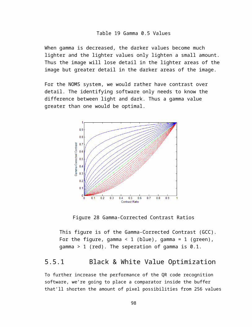
Figure 45 Appearance
Figure 46 Date and Time
99

Manually entering the time and date takes several screens. It’s presented in a natural format with individual screens for time, day, month, and year.
Figure 47 Time Entry Figure 48 Month Entry
Figure 49 Day Entry Figure 50 Year Entry
User profiles is another unique feature of the system. These allow multiple users to customize their experience, their cooking preferences, and individual diet tracking by way of MyFitnessPal integration. This should be easy to set up and the only information that is necessary to do this is a name for the profile and an
100
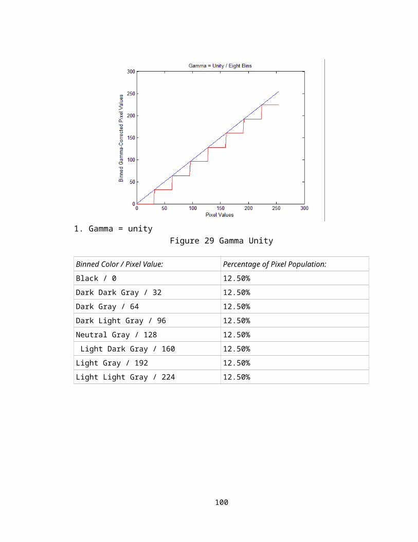
email address. The Email address enables the MFP integration as well as a place to send the coupons generated by the push advertising. Obviously the MyFitnessPal should be an optional component and so that part of the profile setup can be skipped though it does offer great additional benefits. The screens associated with profile management are below in Figures 51 through 54.
Figrure 51 Profiles Figure 52 Name Entry
Figure 53 Email Entry Figure 54 MyFitnessPal
101

All of these systems combine to provide what we hope is a simple an intuitive and simple to use user interface. The user will be able to navigate in a natural way to accomplish whatever they would like on the system. A basic overview of the user interface design flow is shown below in Figure 55.
Figure 55 UI Flow
102

System Display and Touch Screen
9.1 RequirementsThe System Display is an essential component of this system, as such care needed to be exercised in choosing a component which would meet our needs. The display needed to be low cost and yet offer sufficient resolution to display the varying content. The main constraints then are that it must be able to adequately display the camera feed as well as the push advertising. Additionally we wanted a simple solution for allowing the user to interact with the microwave. This could be accomplished in a couple of ways. A small screen could be integrated with a traditional keypad. This approach is simple. It would not be necessary to have a touch screen. The keypad is easily integrated into the system controller. The cost of these simple components is low. However the resolution of these small LCD units is very low and they are almost universally monochrome. Ultimately this approach was rejected in favor of a larger touch screen interface. The small screen and keypad option just did not offer the flexibility that we wanted in this design. The larger screen offers better resolution and user interface flexibility. The larger color screen will offer a much more pleasing aesthetic. The advertisements will be color and much more engaging. It’s possible that video could even be played. The disadvantages of this option include the greater power draw as well as cost associated with the unit.
9.2 LCD SelectionThere were a couple of options when considering which LCD to utilize. The least expensive option would be to get a simple LCD panel with an integrated touch interface. There are endless options for a simple dumb LCD panel but using one of these units introduces additional complexity to the system controller. It would be necessary to handle all user interface at the system controller level. The controller would need to integrate and LCD driver. This make the selection of microprocessor much more limited and expensive. Additionally the complexity of coding all necessary functions onto a system controller which is already handling database management, system control, and wireless communication was simply not ideal.
The second option was to choose an LCD with an onboard controller. These units integrate a microcontroller which is used to drive LCD as well as handle some rudimentary logic functionality. Depending on how robust this system is it could be used to drive the user interface completely separately from the system controller. The obvious advantage being that database management and system control could happen, not only separately, but in parallel resulting in a much better experience for the user. Another benefit is in power. The system controller
103

can go, not just into a low power state, but be completely powered down and then boot by the LCD controller whenever a user event is triggered.
It was ultimately decided that the system would utilize the 4D Systems micro LCD-32PTU. This LCD has onboard logic and storage which would allow us to implement all user interface functions directly on the LCD system. It is a 3.2”, 240x320 color LCD screen. It has an integrated PICASO processor which is proprietary to 4D Systems units, a micro-SD card connector, and even an audio amplifier and speaker. Communication with the system controller can take place via I2C or standard serial pins. The cost of this system is moderate and in fact the additional cost of this LCD is almost entirely offset by being able to use a much less complex microcontroller for the system controller.
9.3 Programming the LCDThe 4D Systems LCD uses a proprietary coding language, but it is similar to C and will be easy to adopt. Additionally 4D Systems provides a robust set of visual and object oriented tools to program the system. These systems will be more than sufficient for coding the user interface and in fact will be much easier than developing in C on the system controller would have been. This will allow for much more rapid development and a parallel workload for prototyping the system, allowing the UI and system controller code base to be developed independently and in parallel.
9.4 LCD and System Controller InterconnectA few options are provided on both the system controller and the LCD module for communications between the two subsystems. A combination of these interfaces will likely be used to enable the different functions necessary within the system. There is an I2C bus on both the LCD and System controller microcontrollers. This bus is relatively low speed and will be used to send and receive process commands in between the two units. An API will be written to abstract this functionality but a working set of the encoding of these commands is provided in the table. All commands implement a send and acknowledge format. If the receiving unit does not acknowledge the command after a set period of time the command will be re-sent. Multiple failed attempts will generate an error code and trigger a reset. The system controller implements a FIFO queue for storing and executing instructions. These can be explicitly managed be the LCD unit or loaded from the onboard queue in the case of a scan.
104

Name Bit String Source DestinationExecute Cooking Instructions
0x0001 LCD SC
Execute the cooking instructions currently loaded into the queue.
Acknowledge Execute 0x8001 SC LCDConfirm that cooking execution has begun.
Pause Execution UI 0x0002 LCD SCPause execution of cooking instructions.
Acknowledge Pause UI 0x8002 SC LCDConfirm that cooking has been paused.
Pause Execution SC 0x8003 SC LCDPause initiated by a hardware event, most likely the door is open
Acknowledge Pause SC 0x0003 LCD SCConfirm that the UI has switched to pause mode.
Halt 0x00FF LCD SCInitiates an all stop and flushes the instruction queue. User has cancelled execution.
Acknowledge Halt 0x80FF SC LCDExecution stopped and queue flushed.
Hard Fault 0xFFFF SC LCDA serious error has occurred likely indicating hardware failure. This will be followed by a system error code.
Load Instruction 0x0004 LCD SCLoad an instruction into the queue. The next line will be an encoded cooking instruction consisting of 4 bits encoding the power level, 11 bits encoding the time in seconds, and a flag enabling the turntable.
Acknowledge Load 0x8004 SC LCDSuccessful load confirmed.
Clear Last Instruction 0x0005 LCD SCClear the last instruction in the queue. This would likely be triggered when a user is entering custom instructions and hits the back key.
Acknowledge Clear Last 0x8005 SC LCDConfirm that the last instruction in the queue has been cleared.
105

Reload Instruction Queue 0x0006 LCD SCUser has canceled override entry. Clear the queue and reload instructions.
Confirm Reload 0x8006 SC LCDReload successfully executed.
Enable Camera 0x0007 LCD SCTurn on the front camera and begin feed via RS422. The system controller will also automatically attempt to decode any UPC that may be found in the image.
Acknowledge Camera 0x8007 SC LCDCamera is on and broadcasting.
Store Instruction 0x0008 LCD SCStore an entry in the cache associated with the current product ID and fill it with the current instruction queue. This will be followed by another word establishing which user to associate the instructions with.
Confirm Store 0x8008 SC LCDStore was successful.
UPC Alert 0x8009 SC LCDBroadcast to the LCD unit when a successful decode has occurred. There is no ACK for this command.
Fetch Product ID 0x000A LCD SCRequests the current product ID stored in the queue on the System Controller.
Sending Product ID 0x800A SC LCDThis command is followed by the product ID currently in the queue.
Fetch Product Details 0x000B LCD SCRequests product details from the system controller that were not found on the LCD cache. This is followed by the product ID that is being requested.
Sending Product Details 0x800B SC LCDWill send a data packet containing a product description for the product ID requested. This should be stored on the LCD cache.
QR Alert 0x800C SC LCDThe internal camera has detected a QR code and it has been decoded by the system controller. This alerts the UI of the event so that it can switch to the scanning output.
106

The System controller will also attempt to send the camera feed to the UI via the serial connection.
QR acknowledge 0x000C LCD SCThe LCD has switched to the scan screen and is receiving the internal camera feed.
Fetch Instruction Queue 0x000D LCD SCRequest the current instruction queue from the system control to coordinate cooking output.
Sending Instruction Queue 0x800D SC LCDA series of encoded cooking commands is sent back to the LCD unit from the instruction queue.
Table 28 Interconnection Protocol
107

Summary of Hardware & Software
1.0 Hardware 4D Systems’ Micro LCD-32PTU Touchscreen LCD TI’s TIVA C Series TM4C123G Launchpad Microcontroller Fabricated Microcontroller – source to be determined TI’s CC3000 BoosterPack Wi-Fi chip Panasonic’s Luxury Full-Size 2.2 cu. ft. Genius Microwave Oven with
Inverter Technology CMOS VGA Camera Module
2.0 Software Code Composer Studios - Microcontroller 4D Systems’ Workshop4 IDE - LCD Touchscreen SDK Installer (Rev.A) - Wi-Fi Chip Microsoft SQL Server Express Edition – Database Management System PCB Planner - Board Fabrication PCB Expedition - Board Fabrication DX Designer - Board Fabrication Microsoft Word - Project Documentation InDesign - Milestone Management Microsoft Visio - Project Documentation LTPOWERCAD – Power Design LTSPICE – Power Simulation
108

Prototype Construction & Coding
1.0 Parts Acquisition & Bill of MaterialsIn order to acquire the parts for our prototyped NOMS system we will be purchasing the parts from the individual vendors themselves such as Texas Instruments, Sanyo, and Lockheed Martin for the fabricated controller board. These parts will be acquired by purchase online and delivered over the Winter break. The fabricated board from Lockheed Martin will actually be most likely donated but if this plan falls through we have a back-up plan with a company called Advanced Circuits.
The Bill of Materials (BOM) section for this document will not be completed until after the fabrication of our System on Chip. For the initial design process we have yet to decide on exactly what we will need on the fabricated microcontroller board and what we will not. For now we will be prototyping using TI’s TIVA C Series TM4C123G Launchpad Microcontroller. When we have successfully prototyped NOMS using this microcontroller we will loosely base our own designed board on what we used and did not use on this prototyping board.
2.0 PCB Vendor & Assembly The controller board that we will be prototyping with will be TI’s TIVA C Series TM4C123G Launchpad Microcontroller. This will be off the shelf and should not require any additions. We will be designing our own controller board in parallel with the design of the other subsystems. The design of this board will be loosely based on the design of the microcontroller board we plan to use from Texas Instruments. In order to acquire this fabricated board we have a couple of options to select from.
The first option we have considered is a company named Advanced Circuits. This company fabricates individual boards without a minimum size or quantity which is exactly what we need. Upon further research into this company’s offers we discovered that Advanced Circuits offers special deals for engineering students on their website. The offer that we would probably take advantage of if we do is the “PCB 4 Layer Full Spec for ONLY $66 Each”. This is actually pretty affordable for the group and if no other option is feasible by the time we need the board fabricated then we will have a good back-up plan.[A]
The next option is one that is available due to the employment of two of our group members. Jared Wach and Tim Miller both work at Lockheed Martin as CWEP interns and are involved in electrical work. Jared Wach specifically works on board design and has access to many design tools used in fabrication of controller boards in addition to the design process itself. It is in this position that NOMS finds a very helpful hand from Lockheed Martin in that it has potentially been offered that we may design and fabricate our controller board at the
109

Lockheed Martin Missiles and Fire Control facility in Orlando. This is our first and best option being that it will be free and include the potential help of professional engineers who will oversee the use of the board fabrication design tools.
3.0 Final Coding PlanThe coding plan for each subsystem has been previously described in detail but will be summarily addressed here for the prototyping section. We plan to use an FPGA to process the images captured by the camera(s) and will use Verilog to write the algorithms that handle all the image processing involved. We plan to use the development kits that come with the prototype microcontroller from Texas Instruments which will follow syntax similar to C or JAVA. The same is true of the Wi-Fi chip selected as well. The LCD touchscreen will have its own microcontroller and will be programmed using the IDE that comes with it called Workshop. This is a free IDE.
110

Prototype Testing
In order to verify that the prototyped NOMS system is working correctly we will need to have a testing plan for each phase of development with test cases and ways to verify that each test case is passed. For each subsystem, we previously identified ways in which we plan to test and verify that the subsystem itself is working. For example, the camera system has its own set of requirements that need to be met each with ways to verify that the requirement has been met and will work properly when completed. Once each subsystem has been tested thoroughly enough that it passes we will need to integrate each system into the whole and verify through more testing that the entire system is working correctly and that each subsystem coordinates with the others properly. This section of the document addresses which environments we will use to test the prototyped NOMS system and then addresses some specific tests that we believe will be beneficial in ensuring that the prototyped NOMS system works correctly. These same tests will also be used to verify that the final product works correctly once we have fabricated our own microcontroller board.
1.0 Test EnvironmentsCode Composer Studios will be used to write and test the system controller payload.
4D Systems’ Workshop4 IDE will be used to write and test the LCD microcontroller’s functionality and interaction between itself and the main system controller.
DX Designer will be used to create a circuit card layout in the high level basics. Testing at this level will include testing for proper line termination, hanging nets, and proper system design.
PCB Expedition is used to lay out all the details of the card layout. Testing at this level is more detailed and includes things like testing for noise, thermal hotspots, and more detail-oriented issues.
2.0 Specific TestingWe will write an API that allows the microcontroller that we prototype with to receive packets over an I2C bus. These packets will be directly routed to the LCD unit to ensure communication is correct. Verification will be done visually, by inspection on the LCD itself. We will be checking for correct imaging, white balancing, de-skewing, and de-warping of the image.
In order to save power and result in a higher efficiency we are going to cause the system controller to enter a sleep-mode when it has not been in use for a specified period of time. In order to achieve this we will have an internal clock
111

running, which when it has reached a certain period of time that it has remained dormant, will switch to sleep-mode.
Another event we will need to consider is when the microwave door is opened. This should cause the microcontroller to turn on from sleep mode. This assumes that the microcontroller is in sleep-mode to begin with as will be tested from the previous test case.
In addition opening the microwave door should turn the interior camera on. This can be tested very simply by checking the camera’s clock to see if it is running. Whenever the clock is running the camera is scanning for images, sending those images to the buffer, and these images are eventually processed by the FPGA. The FPGA will process the images and send these processed images to the microcontroller for use.
Whenever the interior camera is on it should be scanning for QR codes for a specified period of time based on hardware ability in the camera buffer. This can be tested in a similar manner as the previous test case.
The LCD will also come out of sleep-mode and light up whenever the door is opened so that the user will see that NOMS is aware of the user and is ready for use. This will only require a visual inspection to verify that the system is working together properly.
We will also want to ensure that proper communication is taking place from the microcontroller to the microwave system so that when the appropriate signal is sent to the relay switch, the microwave oven should turn on (magnetron turns on).
The microcontroller will communicate through a bus to the LCD touchscreen. This communication link will need to be tested in order to ensure that the user is able to properly communicate with NOMS. In order to test for this we will be able to use the JTAG programming interface to verify that the microcontroller bus is sending and receiving proper signals using the Code Composer Studio.
There are a number of simple tests that will need to take place between the LCD touchscreen and the microcontroller. When a manual instruction is given by the user on the LCD the LCD’s own controller will process those instructions and send them to the microcontroller. We need to be able to verify that when these instructions are passed along that they are passed along correctly. The testing of the LCD’s processing will take place within the subsystem’s own test procedure as seen in its own test plan. This testing will most likely take place between the bus that connects the LCD touchscreen to the main system controller in a similar way to the previous test.
112

An initial test that will need to be run is the verification that the correct UPC or QR codes are being recognized as they are being scanned. In order to do this we will start with a hardcoded image that will be sent to the microcontroller and run through the decoding algorithm. This image will have a known EAN-13 code. We will verify that the algorithm works correctly through a built-in test in the code that will verify that the EAN-13 code is the same one that we already know it should be. This test can be repeated several times and will have to be to ensure that there wasn’t any lucky guesswork going on in the decoding algorithm.
Once the camera has successfully scanned an image of a UPC code or QR code we will want the camera to enter into sleep-since it has fulfilled its purpose temporarily. In order to do this, however, the microcontroller will need to send the signal to it that a valid EAN-13 code was found and is being searched for in the online database. We will need to verify that the camera has ceased scanning for images. This can be done in two ways: the first is by inspection since we will have the images being scanned by the cameras output on the LCD screen. The second way disregards the LCD screen since we could technically stop outputting to the LCD while the cameras continue to scan for images anyway. This test would involve ensuring that the power to the camera’s clock is cut off. When the clock for the camera is off then the clock itself stops scanning images.
The interior camera is not a required camera to have in the NOMS system but will be still need to be tested if and when the NOMS design team decides to implement it into the system. Similar to the last test case, we will want the interior camera to stop scanning for any images when the magnetron is turned on since there should be no need to images once the microwave is operating and also because the radiation will disturb the process of image capture anyway. In order to ensure that this is the case we can actually also ensure that the interior camera is never on unless the microwave door is open. This will be achieved by cutting off the power to this camera from the microcontroller whenever the door is closed. The interior camera, therefore, will only be functional whenever the microwave door is open, and also only for a specified period of time based on the camera buffer.
We will also need to ensure that the cooking instructions that are received from the online database are sent from the database’s server to the microcontroller correctly. This will be a case of causing the microcontroller’s algorithm to output the cook times and power levels in the development environment to verify between the two that they match.
NOMS will also need to have a manual usability section on the LCD so that a user who chooses not to use the automated aspects of NOMS or has food that cannot be scanned can cook their food. These needs to be achieved through the LCD touchscreen which will be required to send the proper signals to the microcontroller indicating a cook time and power level for the microwave to use. This can be verified in two ways: by inspection in checking to see that the
113

microwave does in fact turn on and for the allotted time, though power level would be difficult to track, or by verifying in the code development environment for the microcontroller that the signals received are identified correctly and lead to the correct event of turning on the microwave for the specified period of time and that the power level is set correctly as well.
3.0 ConclusionAs a final thought in the Prototype Testing section of this document it is understood that this is not an all-inclusive list of tests that could be run to validate the functionality of the NOMS prototype. This list is a representative list of things we certainly plan to test and the kinds of tests that will be run to verify correct operation. There will certainly be many more tests that take place as we write code and make connections and implement the many subsystems into the main prototype.
It is also of note that though we did not include a specific testing section for the final NOMS product, we do intend to use these same test cases and environments to test further as we fabricate our own controller board and introduce it into the already-working prototyped NOMS system.
114
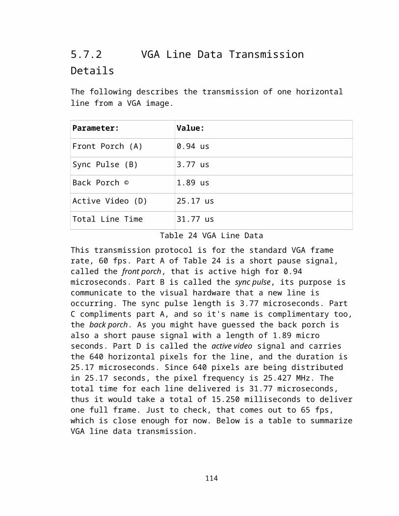
Administrative Content
1.0 BudgetLCD Touch Screen and Controller $80Embedded Wi-Fi Chip $40C-MOS Cameras and Controllers $20Embedded Systems Controller Components
$15
Fabricated Board $70Microwave $250Magnetron: 10QBP1009 $75Turntable: 15QBP0851 $33Fan Motor: $33Lights $5AC/DC Transformer: F606Y8M00AP $155Buzzer $2Regulator $8Total $786
Table 29 Budget
LCD Touch Screen and Controller Embedded Wi-Fi ChipC-MOS Cameras and Controllers Embedded Systems Controller
ComponentsFabricated Board MicrowaveMagnetron: 10QBP1009 Turntable: 15QBP0851Fan Motor: Lights AC/DC Transformer: F606Y8M00AP
Buzzer
Regulator
Figure 56 Budget
2.0 Budget DiscussionThe financial aspect of NOMS is being handled collectively by the group members themselves independent of grants or help from outside companies. We therefore are selecting the most cost-effective parts available to us. The previous budget list is a comprehensive list of all known costs that we will need to be able
115

to cover in the coming semester in order to complete NOMS. There are a few details that may or may not cause the total cost to fluctuate. We have found a couple of microwaves that are free and may be usable for the NOMS project. If this is the case then we may be able to almost cut our budget in half. The list above also includes some redundant parts such as a magnetron and a microwave. Every microwave that can be bought usually contains the magnetron otherwise it is unusable. We have included such redundancies in order to offset any complications that may come up in the design and building stage. Lastly, the fabricated board that we plan to create based loosely on the prototyped board from Texas Instruments may be a free board if we can procure it from Lockheed Martin. In addition to these savings, Texas Instruments offers samples on many of their products including the ones that we plan to use. We may have to order multiple of particular parts in case we run into hardware failures or damage any electronics in the process of installation, integration, or testing. These extra parts may also help us to run multiple subsystems in parallel with multiple microwaves should we have the ability and time to do so.
116

3.0 The Inspiration for NOMS
Time and availability is very important to all engineering students, for time is thinned-out and sleep is rare. NOMS is an idea brought about of general laziness and an inability to cook food. After a long, hard dark of coding and studying, what else would be better than to come home late at night, throw some easy macaroni and cheese in an automatic microwave, and enjoy a few extra moments of Futurama due to not having to input cooking instructions and data into the microwave? This is the inspiration and beauty of NOMS.
NOMS is the perfect cooking equipment for any lazy college student; meaning anyone who has never made a meal of their own, or just doesn’t have the spare seconds to input cooking instructions now has an added convenience. NOMS promises to reduce overcooking or forgetfulness of negligent or overly-tired home chefs.
Another inspiration for NOMS is the want and desire to link everything in the home and kitchen. Originally NOMS was intended to be the beginning of a whole smart kitchen system; where all kitchen equipment would communicate, interact, broadcast, and track all activities in the kitchen. The smart kitchen would track what raw ingredients came from the pantry and refrigerator, and maintain a record of what equipment (such as ovens, toasters, juicers, microwaves, etc) was used, and what food was returned to the pantry and refrigerator. The smart kitchen was a total package.
Another inspiration for NOMS came from the Jetson's television show. The Jetson's are a futuristic nuclear family with a robot servant named Rosie. Rosie would clean the house, walk the dog, and of course cook all the meals. NOMS is just a beginning step towards autonomous food production in the house or home.
NOMS was also inspired by the need for children to be able to safely prepare food for themselves. Cooking can be dangerous for the new and unexperienced. Also the demands and strains of modern parents means that they can't always be there to provide a hot meal or feed their children. Luckily NOMS allows parents to track and record when and what their children eat.
The biggest motivation for NOMS is sheer laziness. The biggest question was, "What is the easiest form to cook for one's self?". NOMS will provide for a need for foolproof cooking in the home, while providing valuable feedback to the users. An experience for anyone. Bon appetite!
117

4.0 Milestone DiscussionMilestones are an important part of any large research project. Determining proper milestones and schedules at the beginning of the semester provides a quick overview of where we need to be as the semester progresses, as well as provides an indication as to whether we are falling behind or not. As a group of four who each have jobs outside of school, it is very important that everyone remains on the same page. By having established goals and weekly meetings, we are able to keep ourselves on track, as well as our teammates. Without this structure, our project would fall apart very quickly as members fell behind. This would make a very stressful working environment, and would hinder any creative communication that could possibly come from working within a group.
This semester was all about deciding on a project and producing a paper. Our group was chosen quickly enough, and a project decided upon. This gave us an advantage, as we were quickly able to start brainstorming ways to make this project more than just your typical microwave project. We pulled our minds together and came up with the idea of a microwave that would be intelligent enough to prepare food, based on bar and QR codes. The additional perk of pushing the food consumption data to a fitness website came as a result of brainstorming sessions. Luckily for us, some of our group members had experience with hands on electronics, which will come in handy next semester.
The first semester’s milestones included breaking the project apart and assigning responsibilities to teammates. We then had to meet with our advisor to make sure our project provided enough design challenge. From there, our main focus was to obtain as much research as possible to aid us with the task of writing the paper towards the end of the semester. We had some deadlines of turning in preliminary research, as well as a rough draft paper submission. We needed to schedule our time to make all of these goals.
We established meetings every other week to make sure everyone was doing their part and this also gave us a chance to communicate with team members along the way. We expected this project to be challenging. We were not disappointed. This project proved to be an enormous undertaking which would not have been possible without the use of team meetings and group goals.
In the images below, we have provided the milestone discussion per senior design class.
118

5.0 Semester 1: Senior Design 1 Milestones
Task Name Initial Date Planned
Date Process
% Successf
ulProject decision 08/30/13 08/30/13 100%Project discussion and splits of categories for each person
09/04/13 09/04/13 100%
Meeting with Dr. Richie to discuss the project
09/22/13 09/22/13 100%
Start researching 09/04/13 09/10/13 100%Finished researching 11/24/13 11/30/13 100%Start paper 09/15/13 09/18/13 60%Complete 10 Pages for Rough Draft Review
11/05/13 11/07/13 90%
Set date to review/ rough paper 11/22/13 12/1/13 100%Meeting 1: Research 08/31/13 08/31/13 100%Meeting 2: Research 09/14/13 09/14/13 100%Meeting 3: Research 09/28/13 09/28/13 100%Meeting 4: Research Paper 10/26/13 10/26/13 15%Meeting 5: Research Paper 11/02/13 11/02/13 30%Meeting 6: Research Paper 11/16/13 11/16/13 60%Meeting 7: Research Paper/ Final Edits
12/01/13 12/01/13 100%
Table 30 Semester 1 Milestones
Our goals and milestones for Senior Design 2 on our NOMS project are all in theory of what we believe and hope would happen. The first real milestone on our chart is the database development for our project. We are hoping to ultimately order all of our parts during the upcoming break, but we have allotted extra time for complications. Parts acquisition should occur before the semester starts, if everything goes according to plan.
From there, we will work on and test all of the parts as we build them, as we do not need the entire microwave to be created in order to ensure individual components work. We will work in teams to provide support during the construction process. We would like to finish our project by early April so we have time at the end for troubleshooting.
119

6.0 Semester 2: Senior Design 2 Milestones
Figure 57 Semester 2 Milestones
120

10.0 About Us
Nakiesa Faraji-TajrishiNakiesa is an electrical engineering major in her senior year at UCF, graduating in May 2014. She comes from a line of engineers including her father who is an electrical engineering consultant for power management. Her brother is an electrical engineering major at Georgia Tech and is graduating this May as well. Nakiesa originally obtained an undergrad degree in Studio Art at Florida State University. Nakiesa currently is interning at Siemens, as an electrical engineering intern in the wind power division. Nakiesa plans to pursue a career in electrical engineering focused on power, ideally accepting a job offer from Siemens in the spring.
Tim MillerTim is a computer engineering major in his senior year at UCF, graduating in May 2014. He received his Associates in Arts from Valencia College in 2011. Tim is currently a CWEP intern at Lockheed Martin in Systems Engineering and has recently accepted a fulltime position upon graduation at Lockheed Martin MFC’s site in Orlando. Tim’s father was an electrical technician for the United States Navy and worked for NASA for over twenty years before moving on to Tektronix. His grandfather was a chemical engineer at Martin as well. Tim’s younger brother also is seeking to become a nuclear engineer for the United States Navy where he will pursue a degree from a University as well in order to further pursue a career in engineering. Coming from an engineering family Tim eventually decided to also pursue engineering as a career.
Tom MizellTom is an electrical engineering major in his senior year at UCF, graduating in May 2014. Mizell attended Santa Fe College and received his Associates of Arts in Engineering. Thomas has experience of founding and operating Bicycle Tutors in Gainesville, Florida. Thomas has had internships at Qualcomm, Siemens, and Gainesville Utility Company, and is currently a grader and private tutor. Tom has recently accepted the position of RFIC Test Engineer at Qualcomm in San Diego, California.
Jared WachJared is a computer engineering major in his senior year at UCF, graduating in May 2014. He previously earned his Associate of Arts from Lake Sumter Community College. He is a non-traditional student coming back after having successfully run a small business here in Central Florida. Air Central operated for nearly a decade before the recession caused the construction industry to bottom out. Seeing an opportunity to pursue his passion of computer engineering he returned to UCF where he is now finishing his degree. He does this despite the
121

challenges of having his concurrently in the UCF College of Nursing and three young children.The GroupThe NOMS group came together after having taken several classes together previously throughout our time at UCF. As time went on we began to study together, join each other’s work groups, and became lab partners. The culmination of this group dynamic has come to a head in the NOMS project and will prove to be a major test for us. Having already worked together so much and knowing so much about each other we should have a strong advantage in working together to pursue the success of this design project that we have embarked upon.
122

8.0 History of Easily-Prepared FoodFor one-hundred-thousand years mankind has had the laborious daily ritual of preparing food for oneself and tribe. In the far past, preparing food required the ability to produce flame from spark (a tough challenge to produce a full flame), then spend hours and hours cooking and preparing the meal. Before the discovery of fire, early proto-man had to eat raw meat, scavenge off dead carcasses, and fight beast and bird for dominance of hunting land.
Then, about seventeen-thousand years ago, agriculture became a huge stepping stone in preparation and cooking of food. New grains, veggies, and meats were now available. This caused mankind to become stuck to the land, rather than being roaming hunters and gathers.
Eight-thousand years ago, civilization rose out of the agricultural centers of Mesopotamia. This allowed man leisure and the ability to specialize their craft. Thus came chefs, bakers, meat markets, butchers, and other new forms of culinary arts.
During the Middle Ages having a meal prepared was for the very rich and traveling pilgrims. During this period, salting a preservation of meat and veggies was created to easily transport high-protein dietary needs while also being about to keep for months at a time. This was the first known form of the pocket snack.
The Italians of the northern mountainous areas of the country side produced the first known frozen specialty to the western world – gelato! Unfortunately gelato was only available during the winter and cold periods of the season. Finally during the nineteenth century, with the invention of streamliners came the ability to transport ice from the frozen north to the warm south, and using an accessory called the ice box allowed snacks and food to be cooked and preserved (without dehydration). This gave people the ability to hold onto food items such as milk, butter, fresh meats, cheese, etc.
During the expansion of the western United States, a new movement in lazy culinary arts formed; the road shack. The road shack allowed travelers to briefly stop and enjoy a quick bite before hitting back down the road, what later became the modern diner.
With the advancement of mechanical innovation came the nickel machine. The nickel machine allowed a customer to grab a snack, such as peanuts or jerky, without a human vendor. This is truly the first time the world had seen autonomous food vending, now a $16,000,000,000 industry worldwide. With the nickel machine came autonomous drink and candy machines.
In the 1920's the automat was created in New York City. The automat was a place where one could pay for food with change, open a drawer, and instantly get the meal of their choice. The food was freshly cooked in a kitchen on the other side of the user. This allowed a full meal with the convenience of not having to dine in.
123

After World War Two, and the advent of the automobile in North America, brought about the modern fast food industry. One could simply drive through the building and pick up the food of their choice.
In the 1960's through military radar technology the microwave oven was born. It was a fantastic change due to the ability to cook food without heating the bowl. Now we have NOMS. NOMS gives us the ability to easily throw food into a machine, the machine knows how to cook it, and your food is done. Easy as pie!
Welcome to the future of cooking.
124

Appendix A – PermissionsQuestion:
Response:

Appendix B - References[1] http://www.smarthome.com/13041/Beyond-Microwave-Oven/p.aspx
[2] http://madebynathan.com/2013/07/10/raspberry-pi-powered-microwave/
[3] http://www.hobartcorp.com/products/cooking/combi-ovens-and-barcode-scanners/
[4] http://www.eecs.ucf.edu/seniordesign/fa2012sp2013/g31/
[5] http://www.eecs.ucf.edu/seniordesign/fa2010sp2011/g15/
[6] http://www.howstuffworks.com/microcontroller.htm
[7] http://www.esfi.org/index.cfm/page/National-Electrical-Code-%28NEC%29/pid/10860
[8] http://www.nbcnews.com/id/27055169/
[9] http://www.madehow.com/Volume-1/Microwave-Oven.html
[10] http://suite101.com/a/microwave-ovens-heat-food-unevenly-a35367
[11]http://scitech.web.cern.ch/scitech/toptech/01/MicroWaveOven/microwave_2.shtml
[12 http://www.eecs.tufts.edu/~dsculley/tutorial/diodes/diodes3.html
[13] http://www.electronics-tutorials.ws/transformer/multiple-winding-transformers.html
[14] http://www.electronics-tutorials.ws/diode/diode_6.html
[15] http://www.allaboutcircuits.com/vol_3/chpt_3/8.html
[16] http://electronics.howstuffworks.com/brushless-motor.htm
[17] http://www.anaheimautomation.com/manuals/forms/brushless-dc-motor-guide.php
[18] http://www.s-line.de/homepages/bosch/sensorless/node9.html
[19] http://www.solarbotics.net/library/pdflib/pdf/motorbas.pdf
[20] http://www.engineersgarage.com/articles/stepper-motors

[21] http://www.radartutorial.eu/08.transmitters/tx08.en.html
[22] http://hyperphysics.phy-astr.gsu.edu/hbase/waves/magnetron.html
[23]http://www.powerqualityworld.com/2011/04/cbema-curve-power-quality-standard.html
[24] http://www.maineelectronics.com
[25] http://www.repairclinic.com/Panasonic-Microwave-Motor-Parts
[26] http://www.repairclinic.com/Microwave-Blower-Wheel-Fan-Blade-Parts
[27] http://www.repairclinic.com/Microwave-Lighting-Light-Bulb-Parts
[28] www.erparts.com
[29] http://www.murata.com/products/catalog/pdf/p37e.pdf
[30] http://www.1728.org/project3.htm
[31] http://www.ixysic.com
[32]http://www.st.com/st-web-ui/static/active/en/resource/technical/document/datasheet/CD00000444.pdf
[33]http://www.gs1.org/docs/gsmp/barcodes/GS1_General_Specifications.pdf
[34]http://webstore.ansi.org/RecordDetail.aspx?sku=BS+ISO%2FIEC+18004%3A200
[35]http://www.ti.com/msp430/
[36]http://www.ti.com/arm/
[37] http://www.ti.com/arm/
[38] http://www.personal.psu.edu/glh10/ist110/topic/topic07/topic07_01.html
[39] http://office.microsoft.com/en-us/access-help/database-basics-HA010064450.aspx
[40] http://www.sqlite.org/
[41] http://www.mysql.com/

[42] https://www.microsoft.com/en-us/sqlserver/default.aspx
[43] http://windows.microsoft.com/en-us/windows-vista/set-up-a-computer-to-computer-ad-hoc-network
[44] https://my.bluehost.com/cgi/help/541
[45] http://www.digi.com/products/wireless-wired-embedded-solutions/zigbee-rf-modules/point-multipoint-rfmodules/xbee-wi-fi
[46] http://www.ti.com/product/cc3000
[A] www.4pcb.com