web engineering conceptual modeling of device- independent web
TRANSCRIPT
Existing tools forbuilding anddeploying complexWeb sites areinadequate fordealing with thesoftware productionprocess that involvesconnecting withunderlying logic in aunified andsystematic way. As asolution, we proposethe OO-H method,an object-orientedsoftware approachthat capturesrelevant propertiesinvolved in modelingand implementingWeb applicationinterfaces.
The Web’s characteristics—ubiquity,open standards, interlinking, easyaccess to information and services,and creating content easily—have cre-
ated new business opportunities, such as e-commerce or online auction systems. Add-itionally, its characteristics have nurtured a needfor both business-to-consumer and business-to-business applications inside the enterpriseboundaries that take advantage of the latesttechonologies. In light of ongoing technologicaldevelopments, our platform strives for a lowersoftware development and maintenance budgetand a flatter learning curve.
We believe that existing software engineeringapproaches can successfully extend to new modelsthat specifically gather Web-related characteristics.We based our decision on three assumptions:
1. Behavior in a Web application can no longerbe restricted to simple information updateoperations, and so it must be addressed in arigorous way.
2. Context information and domain behavior
inside Web applications should be ideallyaddressed with already tested object-orientedsoftware engineering methods, as in any otherdistributed application.
3. In spite of the same underlying logical layer,interface appearance and behavior greatly dif-fer between Web and traditional applications.
Following the trend presented in Manolla1 andConallen,2 our approach—known as the object-oriented-hypermedia (OO-H) method—looks atWeb systems as unified software artifacts wherestructure, behavior, and presentation are all basicpieces that must be properly combined for a correctfinal software product. As its main contribution, theOO-H method provides a standard-based frame-work to capture all the relevant properties involvedin the modeling and implementation of Web appli-cation interfaces. The OO-H method design processinvolves constructing two additional views, whichcomplement those captured in traditional concep-tual modeling approaches that comply with UnifiedModeling Language (UML). The navigation viewextends a class diagram with hypermedia naviga-tion features, and the presentation view uses the dif-ferent elements regarding interface appearance andbehavior to model a series of interconnected tem-plate structures expressed in Extensible MarkupLanguage (XML). An interface pattern catalog anda computer-aided software engineering (CASE) tool(see “CASE Tool” sidebar) complete our proposal.As a result, we obtain a device-independent, front-end specification. The software then automaticallygenerates a Web interface that easily integrates withpreexisting logic modules.
OverviewThe OO-H method is a generic model provid-
ing designers with the semantics and notationnecessary for developing Web-based interfacesand connecting them with previously existingapplication logic modules, thus facilitating appli-cations migration. To achieve this goal, we basedthe OO-H method3 on the information reflectedin a UML-compliant4 approach, known as the OO-method.5 For our purposes (see Figure 1), the OO-method is an automated software productionenvironment whose main constituents are
❚ a set of views to capture the system structure(statics) and behavior (dynamics), and
❚ a model compiler that generates the data
26 1070-986X/01/$10.00 © 2001 IEEE
ConceptualModeling ofDevice-IndependentWeb Applications
Jaime Gómez and Cristina CacheroUniversity of Alicante
Oscar PastorValencia University of Technology
Web Engineering

sources and the logic modules in the desiredimplementation environment.
The OO-H method extends these views withtwo new complementary diagrams. The naviga-tional access diagram (NAD) defines a navigationview, and the abstract presentation diagram (APD)gathers the concepts related to presentation. Boththe NAD and the APD capture the interface-related design information with the aid of a set ofpatterns, defined in an interface pattern catalogintegrated in the OO-H method proposal.
Following the OO-method philosophy, theOO-H method provides a model compiler thatgenerates the Internet application front-end forthe desired client platform and/or language(HTML, XML, and Wireless Markup Language, orWML). This extension provides a true three-tieredInternet solution, as observed in Figure 1.
OO-H method proposalThe OO-H method includes the following set
of notations, techniques, and tools that make upa sound approach to the Web product modelingphase:
❚ a design process,
❚ a pattern catalog,
❚ a NAD,
❚ an APD, and
❚ a CASE tool that automates the developmentof Web applications modeled with the OO-Hmethod.
Design processThe design process defines the phases the
designer has to cover for building a functionalinterface that fulfills the user requirements. As we
27
CASE ToolThe CASE tool provides an operational environment that supports all the
methodological aspects of the OO-H method. It simplifies the design andimplementation of Web-based information systems from an object-orientedperspective, providing a comfortable and friendly interface for elaboratingthe OO-H method models. The most interesting contribution of this CASEenvironment is its ability to generate the Web application front-end in well-known industrial software development environments. Figure A shows a snap-shot of the CASE tool. It captures a NAD instance for the sample discussionlist application, which includes an abstraction of the participateInDListnavigational target.
Figure A. The OO-H method CASE tool.
00-H method approach
Problem space Solution space
Data sources
Application logic
HTML XML WAP
Internet applicationfront end
Complementaryviews
Static
Conceptualmodel
Modelcompiler
Modelcompiler
Dynamic
00-methodapproach
(UML-compliant)
Navigation
Presentation
NAD
APD
Pattern catalog
Thre
e-tie
red
Inte
rnet
sol
utio
n
Figure 1. OO-H method:
an overview.
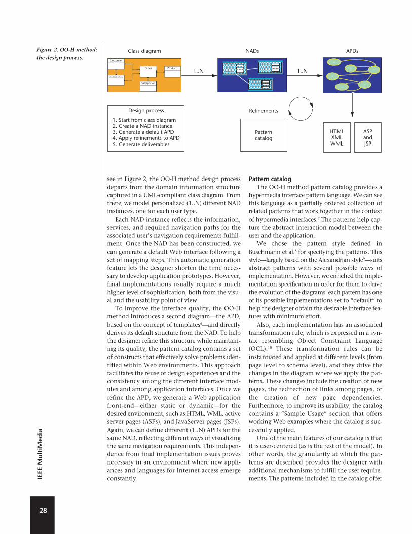
see in Figure 2, the OO-H method design processdeparts from the domain information structurecaptured in a UML-compliant class diagram. Fromthere, we model personalized (1..N) different NADinstances, one for each user type.
Each NAD instance reflects the information,services, and required navigation paths for theassociated user’s navigation requirements fulfill-ment. Once the NAD has been constructed, wecan generate a default Web interface following aset of mapping steps. This automatic generationfeature lets the designer shorten the time neces-sary to develop application prototypes. However,final implementations usually require a muchhigher level of sophistication, both from the visu-al and the usability point of view.
To improve the interface quality, the OO-Hmethod introduces a second diagram—the APD,based on the concept of templates6—and directlyderives its default structure from the NAD. To helpthe designer refine this structure while maintain-ing its quality, the pattern catalog contains a setof constructs that effectively solve problems iden-tified within Web environments. This approachfacilitates the reuse of design experiences and theconsistency among the different interface mod-ules and among application interfaces. Once werefine the APD, we generate a Web applicationfront-end—either static or dynamic—for thedesired environment, such as HTML, WML, activeserver pages (ASPs), and JavaServer pages (JSPs).Again, we can define different (1..N) APDs for thesame NAD, reflecting different ways of visualizingthe same navigation requirements. This indepen-dence from final implementation issues provesnecessary in an environment where new appli-ances and languages for Internet access emergeconstantly.
Pattern catalogThe OO-H method pattern catalog provides a
hypermedia interface pattern language. We can seethis language as a partially ordered collection ofrelated patterns that work together in the contextof hypermedia interfaces.7 The patterns help cap-ture the abstract interaction model between theuser and the application.
We chose the pattern style defined inBuschmann et al.8 for specifying the patterns. Thisstyle—largely based on the Alexandrian style9—suitsabstract patterns with several possible ways ofimplementation. However, we enriched the imple-mentation specification in order for them to drivethe evolution of the diagrams: each pattern has oneof its possible implementations set to “default” tohelp the designer obtain the desirable interface fea-tures with minimum effort.
Also, each implementation has an associatedtransformation rule, which is expressed in a syn-tax resembling Object Constraint Language(OCL).10 These transformation rules can beinstantiated and applied at different levels (frompage level to schema level), and they drive thechanges in the diagram where we apply the pat-terns. These changes include the creation of newpages, the redirection of links among pages, orthe creation of new page dependencies.Furthermore, to improve its usability, the catalogcontains a “Sample Usage” section that offersworking Web examples where the catalog is suc-cessfully applied.
One of the main features of our catalog is thatit is user-centered (as is the rest of the model). Inother words, the granularity at which the pat-terns are described provides the designer withadditional mechanisms to fulfill the user require-ments. The patterns included in the catalog offer
28
IEEE
Mul
tiM
edia
Class diagram NADs APDs
1..N 1..N
Refinements
Patterncatalog
HTMLXMLWML
ASPandJSP
Design process
1. Start from class diagram2. Create a NAD instance3. Generate a default APD4. Apply refinements to APD5. Generate deliverables
Salesperson
Order Product
Customer
Scheduled delivery
Figure 2. OO-H method:
the design process.

alternative solutions to well-known hypermediaproblems, considered from the user’s point ofview. Furthermore, its use lets the designerchoose the most suitable among a set of alterna-tive implementations, depending on the targetapplication domain and on the designer’sexperience.
We show the structure of the catalog in Figure3. The main categories are
1. Information patterns. Provide the user with use-ful application context information. One ofthe most relevant examples is the “locationpattern” whose definition we present below.
2. Interaction patterns. Involve user-interface com-munication issues regarding both functional-ity and navigation.
3. User schema evolution patterns. Cover structur-al advanced features. As an example, we cancite the multiview pattern, which lets thedesigner present two or more simultaneousviews of the information.
In the OO-H method, we can apply differentsets of patterns to the two different diagrams of
the modeling process—that is, the NAD and APDdiagrams. At the NAD level, we can apply patternsrelated to user information selection and naviga-tion behavior. At the APD level, however, we canapply patterns that provide the interface withnonmandatory additional features, which aim toimprove its usability. As an example, a simplifieddefinition of the location pattern follows:
1. Name: location pattern
2. Application level: APD
3. Context: A component gives informationabout the location context of the user insidethe application.
4. Problem: The lack of a user mental schemawhen navigating through hypertext pages cancause the lost in the hyperspace syndrome. Toavoid this problem and improve the usabilityof the interface, we need a mechanism to pro-vide location information. We associate twoforces with this problem:
❚ The path used to reach the information com-ponents isn’t known a priori.
29
Ap
ril–June 2001
Information patterns
Interaction patterns
Static navigation patterns
CycleTree
SequenceSplit-joinDynamic
Command observer patternConfirmation pattern
Dynamic navigation patterns
Navigation patterns
Location patternInterface state patternSystem state pattern
Destination announcement patternError pattern
Success patternHelp pattern
Population observer patternActive agent observer pattern
User schema evolution patterns
Multiview pattern
Identification patternPopulation filtering pattern
Flow patterns
IndexGuided tour
Indexed guided tourShowall
Jump patterns
Annotation patternChooser pattern
Navigation observer patternNavigation selector pattern
Command control patterns
Figure 3. Pattern catalog.
❚ The location component should be looselycoupled—the system view shouldn’t dependon details of the location components.
5. Solution: Implement a mechanism in which achange on the view causes a change propaga-tion that restores the consistency between theview and the location component.
6. Default implementation: Associate a mean-ingful header and footer to each group of relat-ed pages (see the “Abstract PresentationDiagram” section).
7. Other implementations: Adapt the observerpattern11 to hypermedia environments.
Navigational access diagramFor a more general perspective of the approach,
we’ll use a discussion list management system as anexample. As a basic explanation (for reasons ofbrevity), we assume the list manager system con-tains several discussion lists dealing with differentWeb technology topics, and the system forms eachlist by a set of hierarchically ordered messages relat-ing to each other through a parent–child unaryrelationship. The discussion list user can read allthe messages included inside any lists and reply toany of them.
We previously noted that one or more NADscapture the navigation model. Designers shouldconstruct as many NADs as different views of thesystem are required, and they should provide atleast one different NAD for each user type (agent
type) allowed to navigate through the system. ANAD is based on four types of constructs: naviga-tional classes, navigational targets, navigationallinks, and collections. Also, when defining thenavigation structure, designers must considersome orthogonal aspects, such as the desired nav-igation behavior, the object population selection,the order in which objects should be navigated, orthe cardinality of the access. We capture these fea-tures by different kinds of navigation patterns andfilters associated with links and collections. Wefurther develop these concepts below.
❚ Navigational classes. Enriched domain classeswhose attributes and method visibility havebeen restricted according to the user access per-missions and navigation requirements. A sam-ple enrichment is the differentiation amongthree types of attributes: V-attributes (visibleattributes), R-attributes (referenced attributes,which are displayed after a user demand), andH-attributes (hidden attributes, which are onlydisplayed when an exhaustive system popula-tion view is required—for example, for coderefinement reasons).
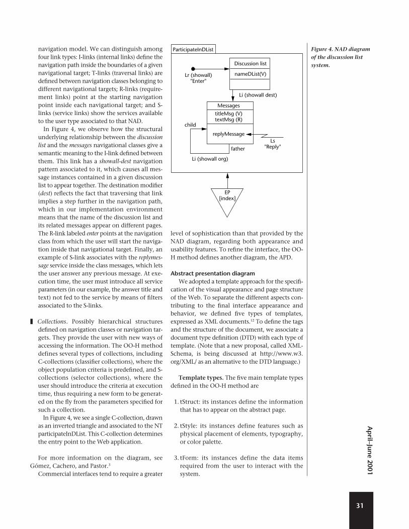
In our example (see Figure 4), we model twodomain classes. The discussion list class definesthe discussion topics available in the discussionlist manager system, while the messages classcontains the different messages and replies sentby the users. The discussion list class has a singleattribute, the nameDList attribute, modeled as aV-attribute. This name unambiguously identifieseach discussion topic inside the interface, and soit must always be present. Besides its identifyingattribute titleMsg, the messages class has a fieldnamed textMsg, modeled as an R-attribute. Thisfact implies that the user has to explicitly clickon its reference to read the message.
❚ Navigational targets. Group the elements of themodel that collaborate in the coverage of eachuser navigational requirement.
In the example (see Figure 4), we observehow there’s a single navigational requirement,participateInDList, that contains both theinformation and the services needed for theuser to effectively navigate the system.
❚ Navigational links. Define the navigation pathsthe user can follow through the system. Theymay have both a navigation pattern and a set ofnavigation filters associated, which provideadditional information to construct the user
30
IEEE
Mul
tiM
edia
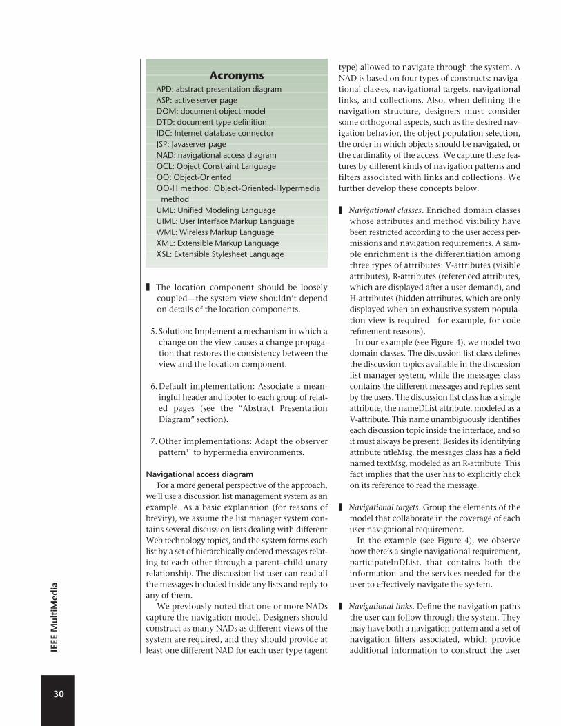
AcronymsAPD: abstract presentation diagramASP: active server pageDOM: document object modelDTD: document type definitionIDC: Internet database connectorJSP: Javaserver pageNAD: navigational access diagramOCL: Object Constraint LanguageOO: Object-OrientedOO-H method: Object-Oriented-Hypermediamethod
UML: Unified Modeling LanguageUIML: User Interface Markup LanguageWML: Wireless Markup LanguageXML: Extensible Markup LanguageXSL: Extensible Stylesheet Language
navigation model. We can distinguish amongfour link types: I-links (internal links) define thenavigation path inside the boundaries of a givennavigational target; T-links (traversal links) aredefined between navigation classes belonging todifferent navigational targets; R-links (require-ment links) point at the starting navigationpoint inside each navigational target; and S-links (service links) show the services availableto the user type associated to that NAD.
In Figure 4, we observe how the structuralunderlying relationship between the discussionlist and the messages navigational classes give asemantic meaning to the I-link defined betweenthem. This link has a showall-dest navigationpattern associated to it, which causes all mes-sage instances contained in a given discussionlist to appear together. The destination modifier(dest) reflects the fact that traversing that linkimplies a step further in the navigation path,which in our implementation environmentmeans that the name of the discussion list andits related messages appear on different pages.The R-link labeled enter points at the navigationclass from which the user will start the naviga-tion inside that navigational target. Finally, anexample of S-link associates with the replymes-sage service inside the class messages, which letsthe user answer any previous message. At exe-cution time, the user must introduce all serviceparameters (in our example, the answer title andtext) not fed to the service by means of filtersassociated to the S-links.
❚ Collections. Possibly hierarchical structuresdefined on navigation classes or navigation tar-gets. They provide the user with new ways ofaccessing the information. The OO-H methoddefines several types of collections, includingC-collections (classifier collections), where theobject population criteria is predefined, and S-collections (selector collections), where theuser should introduce the criteria at executiontime, thus requiring a new form to be generat-ed on the fly from the parameters specified forsuch a collection.
In Figure 4, we see a single C-collection, drawnas an inverted triangle and associated to the NTparticipateInDList. This C-collection determinesthe entry point to the Web application.
For more information on the diagram, seeGómez, Cachero, and Pastor.3
Commercial interfaces tend to require a greater
level of sophistication than that provided by theNAD diagram, regarding both appearance andusability features. To refine the interface, the OO-H method defines another diagram, the APD.
Abstract presentation diagramWe adopted a template approach for the specifi-
cation of the visual appearance and page structureof the Web. To separate the different aspects con-tributing to the final interface appearance andbehavior, we defined five types of templates,expressed as XML documents.12 To define the tagsand the structure of the document, we associate adocument type definition (DTD) with each type oftemplate. (Note that a new proposal, called XML-Schema, is being discussed at http://www.w3.org/XML/ as an alternative to the DTD language.)
Template types. The five main template typesdefined in the OO-H method are
1. tStruct: its instances define the informationthat has to appear on the abstract page.
2. tStyle: its instances define features such asphysical placement of elements, typography,or color palette.
3. tForm: its instances define the data itemsrequired from the user to interact with thesystem.
31
Ap
ril–June 2001
ParticipateInDList
Lr (showall)"Enter"
Li (showall dest)
Li (showall org)
Discussion list
nameDList(V)
Messages
titleMsg (V)textMsg (R)
replyMessage
child
father
Ls"Reply"
EP[index]
Figure 4. NAD diagram
of the discussion list
system.

4. tFunction: its instances capture client func-tionality. They’re based on the documentobject model (DOM) specification (seehttp://www.w3.org/XML/), which aims togive a platform and language-independentinterface to the structure and content of XMLand HTML documents. It also seeks to stan-dardize an interface for these objects for nav-igation and document processing. Thefunctions defined in this kind of template arelanguage-independent, so they must bemapped to a target language (eitherJavaScript, which captures HTML-specificcomponents of the DOM, or another) tobecome operative.
5. tWindow: its instances define a set of simulta-neous views available to the user.
For reasons of brevity, we only show the tStructDTD. A DTD specifies the set of rules defining avalid XML document. It thus defines the tags thatappear in any template belonging to that type, theelements it may contain, and its attribute assign-ments. It also contains other information, such asprocessing instructions, a document type declara-tion, comments, and so on.
<!ELEMENT collection (object+|link*)>
<!ATTLIST collection
format (ulist|olist) “ulist”
style CDATA #IMPLIED
>
<!ELEMENT link (call)*>
<!ATTLIST link
name ID #REQUIRED
type (string|button|image|menuitem
|automatic) “string”
show (here|new) “new”
pointsTo
(tForm|tWindow|tFunction|tStyle
|tStruct|command) “tStruct”
dest CDATA #REQUIRED
>
<!ELEMENT object (attrib+|call*)>
<!ATTLIST object
type CDATA #REQUIRED
style CDATA #IMPLIED
>
<!ELEMENT attrib (call)*>
<!ATTLIST attrib
name ID #REQUIRED
type
(string|date|text|integer|anchor|…)
#REQUIRED
order (yes|no) “no”
>
<!ELEMENT call EMPTY>
<!ATTLIST call
event (onChange|onClick|onLoad|…)
#REQUIRED
function CDATA #REQUIRED
>
<!ELEMENT label EMPTY>
<!ATTLIST label
text CDATA
>
Looking at this DTD, we can infer the following:
1. A tStruct consists of a set of collections (whichmust contain at least one object) and anynumber of links. Collections have a defaultformat associated (unordered list) and couldalso have a user-defined style (captured in themodel inside a tStyle template).
2. A call, which can associate with every elementof the page, defines the trigger condition forthe interface to perform an action.
3. A link can have zero or more calls associatedto it. A name, a type, and a set of attributesrelated to its behavior define a link (where it’sgoing to show the destination page, whichone is the destination page, and its type). Inthe APD, we show only links with the showattribute set to new (meaning that they pointto a new abstract page).
4. An object contains one or more attributes andzero or more calls. It also has both a type (classto which it belongs) and a style (possibly miss-ing) associated to it.
5. An attribute can have any number of callsassociated to it. It also has a name (required),a type, and a Boolean order value that indi-cates whether the order in which the objectsappear on the screen depends on the value ofthat attribute.
6. A tStruct page can have any number of labelsthat capture the static text appearing in theinterface.
We can derive the default template structurefrom the information captured in the NAD com-
32
IEEE
Mul
tiM
edia
bined with a set of defaults defined for the unde-fined values.
Default APD. The OO-H method defines a setof steps for the mapping of the different elementscontained in the NAD diagram into the equiva-lent elements in the APD.
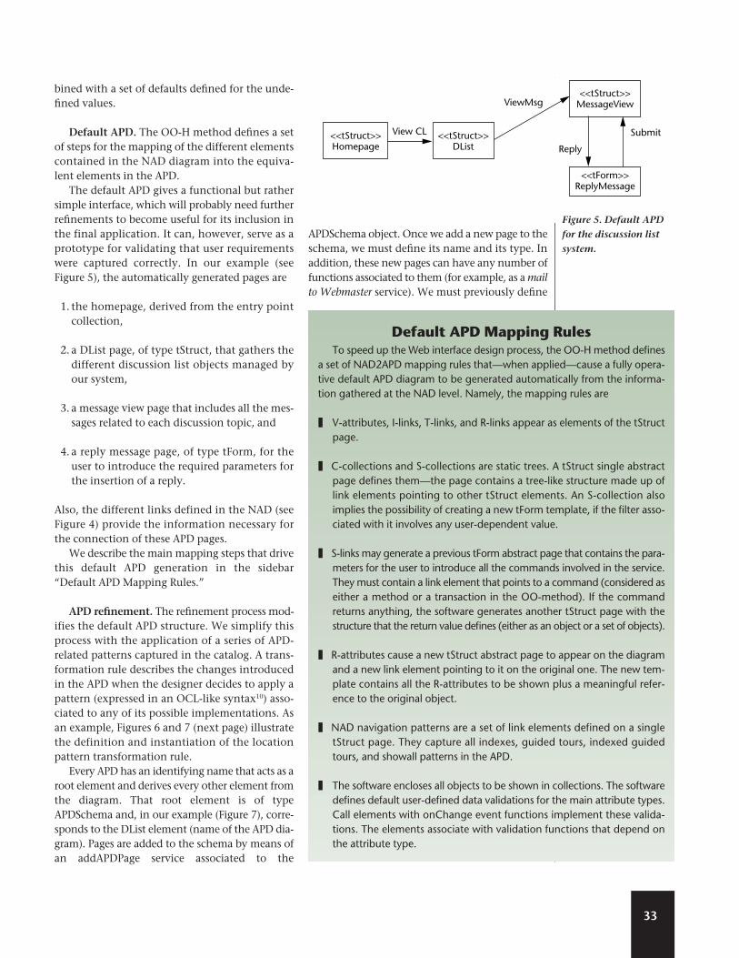
The default APD gives a functional but rathersimple interface, which will probably need furtherrefinements to become useful for its inclusion inthe final application. It can, however, serve as aprototype for validating that user requirementswere captured correctly. In our example (seeFigure 5), the automatically generated pages are
1. the homepage, derived from the entry pointcollection,
2. a DList page, of type tStruct, that gathers thedifferent discussion list objects managed byour system,
3. a message view page that includes all the mes-sages related to each discussion topic, and
4. a reply message page, of type tForm, for theuser to introduce the required parameters forthe insertion of a reply.
Also, the different links defined in the NAD (seeFigure 4) provide the information necessary forthe connection of these APD pages.
We describe the main mapping steps that drivethis default APD generation in the sidebar“Default APD Mapping Rules.”
APD refinement. The refinement process mod-ifies the default APD structure. We simplify thisprocess with the application of a series of APD-related patterns captured in the catalog. A trans-formation rule describes the changes introducedin the APD when the designer decides to apply apattern (expressed in an OCL-like syntax10) asso-ciated to any of its possible implementations. Asan example, Figures 6 and 7 (next page) illustratethe definition and instantiation of the locationpattern transformation rule.
Every APD has an identifying name that acts as aroot element and derives every other element fromthe diagram. That root element is of typeAPDSchema and, in our example (Figure 7), corre-sponds to the DList element (name of the APD dia-gram). Pages are added to the schema by means ofan addAPDPage service associated to the
APDSchema object. Once we add a new page to theschema, we must define its name and its type. Inaddition, these new pages can have any number offunctions associated to them (for example, as a mailto Webmaster service). We must previously define
33
<<tStruct>>MessageView
<<tStruct>>Homepage
<<tStruct>>DList
<<tForm>>ReplyMessage
Submit
Reply
View CL
ViewMsg
Figure 5. Default APD
for the discussion list
system.
Default APD Mapping RulesTo speed up the Web interface design process, the OO-H method defines
a set of NAD2APD mapping rules that—when applied—cause a fully opera-tive default APD diagram to be generated automatically from the informa-tion gathered at the NAD level. Namely, the mapping rules are
❚ V-attributes, I-links, T-links, and R-links appear as elements of the tStructpage.
❚ C-collections and S-collections are static trees. A tStruct single abstractpage defines them—the page contains a tree-like structure made up oflink elements pointing to other tStruct elements. An S-collection alsoimplies the possibility of creating a new tForm template, if the filter asso-ciated with it involves any user-dependent value.
❚ S-links may generate a previous tForm abstract page that contains the para-meters for the user to introduce all the commands involved in the service.They must contain a link element that points to a command (considered aseither a method or a transaction in the OO-method). If the commandreturns anything, the software generates another tStruct page with thestructure that the return value defines (either as an object or a set of objects).
❚ R-attributes cause a new tStruct abstract page to appear on the diagramand a new link element pointing to it on the original one. The new tem-plate contains all the R-attributes to be shown plus a meaningful refer-ence to the original object.
❚ NAD navigation patterns are a set of link elements defined on a singletStruct page. They capture all indexes, guided tours, indexed guidedtours, and showall patterns in the APD.
❚ The software encloses all objects to be shown in collections. The softwaredefines default user-defined data validations for the main attribute types.Call elements with onChange event functions implement these valida-tions. The elements associate with validation functions that depend onthe attribute type.

these functions in afunction repositorymade available to theAPD by a tFunctionLibabstract page. Also, wecould decide to associ-
ate a style to these newly created pages and/or somelinks to other pages, such as the site’s homepage.
In Figure 8, the application of the transforma-tion rule instantiation (Figure 7) to the DListdefault APD shown in Figure 5 causes two newpages to appear: a header and a footer page. Thesepages relate to every tStruct and tFunction page inthe diagram, which essentially means that everypage generated from that APD shares the samelayout context. The foot page has two relatedfunctions: mail and back, whose behavior theabstract tFunctionLib page describes. Also, thetransformation rule adds a link from the head
construct to the application homepage.In our example (Figure 8), the application of an
error pattern similarly causes a new abstracttStruct page to appear on the schema, as well as aset of dependency arrows to specify the pageswhere an error might occur. Furthermore, thedesigner has applied the multiview pattern, whichcreates a tWindow construct.
Generally speaking, patterns might cause anykind of abstract page to appear or be modified. Asa further example, applying the confirmation pat-tern would cause a confirm function to be includ-ed before requesting any change of the typespecified to the system. Therefore, the content ofthe function page—where we include the clientlogic—would change.
In the OO-H method, you can also choosewhether to make the chosen patterns visible. Forexample, the physical pages and the set of arrows
34
IEEE
Mul
tiM
edia
//Create the new pages
[<APDSchema>->addAPDPage(varpage);
varpage.name=<pagename>
varpage.type=’Tstruct’;
//associated tfunctionlibfunctions
(nonmandatory)
[fvarpage= <APDSchema>->
select(type=’tFunctionLib’);
<APDSchema>->select
(name=varpage.name)->
AddFunction
(fvarpage.function);]
//associated tstyle page
(nonmandatory)
[svarpage=<APDSchema>->
select(name=<stylename>);
varpage.IncludeStyle(svarpage);]?
//create links to other pages
(nonmandatory)
[otherpage=<APDSchema>->
select(name=<otherpagename>);
varpage->AddLink(<othervarpage>);]*
]+
//Link new pages to existing APD
structure
[<pagecontext>->select
(type=’Tstruct’ or
type=’Tform’)->Include
StructPage (varpage,
position) ||
[<pagecontext>->select
(type=’Tstruct’ or
type=’Tform’)->Include
StructPage (varpage,
position)]+
Figure 6. Location
pattern transformation
rule.
//Create the new pages
Dlist->addAPDPage(h); h.name’head’
h.type=’Tstruct’
Dlist->addAPDPage(h); f.name’foot’
f.type=’Tstruct’
//Add foot functions (they must be
previously defined in the
tFunctionlib Page)
fl=Dlist->select
(type=’tFunctionLib’);
Dlist->select(name=’foot’)->
AddFunction
(fl.mail);
Dlist->select(name=’foot’)->
AddFunction
(fl.back);
//add a link from head to home page
home=Dlist->select(name=’homepage’);
Dlist->select(name=’head’)->
AddLink(home);
//Link new pages to existing APD
structure
Dlist->select(type=’Tstruct’ or
type=’Tform’)
->IncludeStructPage
(h,Beginning); Dlist->select(type=’Tstruct’ or
type=’Tform’)->IncludeStructPage (f,End);
Figure 7. Transformation rule instantiation for the location pattern.
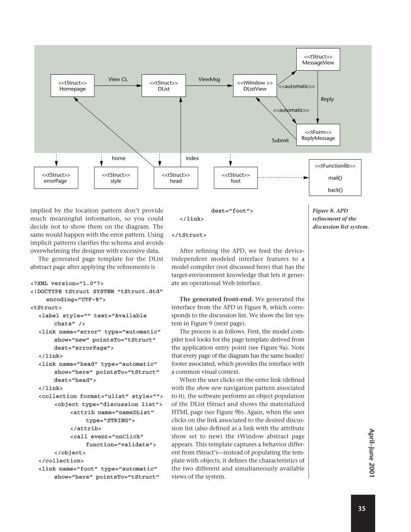
implied by the location pattern don’t providemuch meaningful information, so you coulddecide not to show them on the diagram. Thesame would happen with the error pattern. Usingimplicit patterns clarifies the schema and avoidsoverwhelming the designer with excessive data.
The generated page template for the DListabstract page after applying the refinements is
<?XML version=”1.0”?>
<!DOCTYPE tStruct SYSTEM “tStruct.dtd”
encoding=”UTF-8”>
<tStruct>
<label style=““ text=”Available
chats” />
<link name=”error” type=”automatic”
show=”new” pointsTo=”tStruct”
dest=”errorPage”>
</link>
<link name=”head” type=”automatic”
show=”here” pointsTo=”tStruct”
dest=”head”>
</link>
<collection format=”ulist” style=””>
<object type=”discussion list”>
<attrib name=”nameDList”
type=”STRING”>
</attrib>
<call event=”onClick”
function=”validate”>
</object>
</collection>
<link name=”foot” type=”automatic”
show=”here” pointsTo=”tStruct”
dest=”foot”>
</link>
</tStruct>
After refining the APD, we feed the device-independent modeled interface features to amodel compiler (not discussed here) that has thetarget-environment knowledge that lets it gener-ate an operational Web interface.
The generated front-end. We generated theinterface from the APD in Figure 8, which corre-sponds to the discussion list. We show the list sys-tem in Figure 9 (next page).
The process is as follows. First, the model com-piler tool looks for the page template derived fromthe application entry point (see Figure 9a). Notethat every page of the diagram has the same header/footer associated, which provides the interface witha common visual context.
When the user clicks on the enter link (definedwith the show new navigation pattern associatedto it), the software performs an object populationof the DList tStruct and shows the materializedHTML page (see Figure 9b). Again, when the userclicks on the link associated to the desired discus-sion list (also defined as a link with the attributeshow set to new) the tWindow abstract pageappears. This template captures a behavior differ-ent from tStruct’s—instead of populating the tem-plate with objects, it defines the characteristics ofthe two different and simultaneously availableviews of the system.
35
Ap
ril–June 2001
<<tStruct>>MessageView
<<tStruct>>Homepage
<<tStruct>>errorPage
<<tStruct>>style
<<tStruct>>head
<<tStruct>>foot
<<tFunctionlib>>
mail()
back()
<<tStruct>>DList
<<tWindow >>DListView
<<tForm>>ReplyMessage
ViewMsgView CL
home index
<<automatic>>
<<automatic>>
Reply
Submit
Figure 8. APD
refinement of the
discussion list system.

The tWindow therefore defines two links whosetype is set to automatic (because they don’t requireuser interaction). These links are in charge of load-ing the two current views: the messages kept onthe system (again a tStruct abstract page) and a
form with fields that the user must fill out to adda new message to the application (see Figure 9c).
The addMessage function returns a Booleanvalue, which makes the final confirmation messageappear once the operation is successfully complet-ed (see Figure 9d).
We developed the sample application usingJavaServer pages and Java Bean components (seehttp://java.sun.com) as the server technology andHTML as the client technology.
The model compiler design lets code be gener-ated for other environments. Figure 10 shows asnapshot of the interface generated from the samespecification for a different appliance (in this case,a WAP device).
Comparison with related workInterface designers have traditionally tackled
their tasks using appliance-specific languagesdirectly. That is the case of many commercialapplications and technologys, such as InternetDatabase Connection (IDCs), ASPs (Microsoft), orCold Fusion (Allaire). This approach has many dis-advantages (see http://www.uiml.org), includinglack of support for several target environments(mobile devices, voice, speech), need for thedesigner to perform error-prone activities (directaccess to databases, explicit page linking), highcost of prototyping, difficulty in reasoning andextracting knowledge about the most suitablesolutions to detected usability problems, or thedifficulty of evaluating interfaces.
We identified several proposals that providepartial solutions to these problems and use tem-plate-based Web engineering tools. Of particularinterest are those that use XML instead of beingHTML-oriented. This fact provides them with agreater level of flexibility. For example, MyXML(see http://www.infosys.tuwien.ac.at/myxml/) isa template engine based on XML and Extensible
36
IEEE
Mul
tiM
edia
Figure 10. Discussion list system in a WAP device.
Figure 9. (a)
Discussion list entry
point. (b) Available
discussion lists. (c and
d) Adding an opinion
to the list.
(a)
(b)
(c)
(d)

Stylesheet Language (XSL) for generating eitherstatic or dynamic sites. User Interface MarkupLanguage (UIML—see http://www.uiml.org) isanother XML-compliant markup language thatspecifically tackles the problem of a device-independent description of user interfaces. It pro-vides an event mechanism to communicate withunderlying logic modules. It also proposes somenew orthogonal system views for functionalityand interface widgets, and the whole definition ofthe interface (from structure to styles to presenta-tion to rendition for a given device) is encapsu-lated in a single document. Other systems, suchas Strudel,13 have gone one step further and inte-grated heterogeneous information sources as aprevious step from which to build the structure ofthe Web application and to generate the HTMLrepresentation of pages. This aspect isn’t consid-ered in our proposal, as our point of departure isa structured object-oriented information model.
These solutions clearly separate logic, layout,and structure, thereby facilitating code reuse andsite maintenance. Also, they explicitly give sup-port to dynamically generated Web content.Furthermore, UIML and MyXML provide mecha-nisms for connecting with underlying logic.However, they’re still closer to the solution spacethan to the conceptual (domain problem) space,even if they adopt a more abstract approach thancommercial applications.
We also base the OO-H method on a set ofXML-compliant specifications. The main contri-bution of the OO-H method at this point is ourextensible taxonomy of templates, which intro-duces a broader separation of the different con-cepts involved in the construction of a Webinterface. For example, the tFunction view of theinterface, adds a client–logic abstract definitioncomponent to the other views of the system, andtherefore facilitates the maintenance and/orchange of target language for this client logic. As afurther advantage, these specifications try to keepas close as possible to some well-known XML stan-dard proposals. This limits the designer’s need tolearn new languages and specifications to under-stand the semantics underlying the templates.Following our example, the OO-H bases theabstract definition of the client logic in the OO-Hmethod on the DOM interface model.
The OO-H method also increases the level ofabstraction at which it defines a Web interfaceand is, therefore, much closer to another group ofproposals that tackle the modeling problem froma conceptual point of view. Within these
approaches, the UML community has presentedits proposal for modeling Web architectures.2 Useof a standard UML notation and the distinctionbetween server-side aspects and client-side aspectsare two of its main features. Although using pro-totypes adds flexibility to the way the designer canapproach the modeling process, this approach hasmore to do with the physical software modulestructure than with the logical analysis of theapplication structure. Consequently, it greatly dif-fers from our approach.
Other well-known proposals include Araneus,6
AutoWeb,9 HDM2000,14 or OO-HDM,15 which clear-ly separate structure, navigation, and presentationfeatures. They also share many of the concepts iden-tified in the classical hypertext theory—such as thatof collections, navigational classes, or perspectives—with the OO-H method. Furthermore, our approachis—like OO-HDM15—user centered (as it relies onuser requirements) and object oriented. This allowedus to use the knowledge domain implicit in object-oriented models to improve the interface usability.The inclusion of a pattern catalog and the way thesepatterns can apply to the different diagrams to mod-ify both the model and the final implementation areclosely related to this usability concept and are oneof the main contributions of our method.
Another characteristic of other approaches isthat they’re based on hypermedia systems, whichtarget to the information navigation and visual-ization.16 As a result, they don’t deal with complexfunctionality, either on the client or on the server,which current Web environments need and weexplicitly tackle in the OO-H method.
The appearance of new technologies and stan-dards such as XML—which were present from thevery beginning of the OO-H method—caused manyof those proposals to evolve. This proved true forAraneus-XML17 (Araneus model translation toXML), WebComposition18 (an extension to the OO-HDM model), and WebML19 (AutoWeb evolution).
With regard to business logic interaction, all ofthese new proposals already integrate some sim-ple functionality (such as update operations).Developers are now working on the specificationof complex business logic and rules. In contrast,the OO-H method centers on defining and inte-grating Web interfaces with existing businessmodules. As a result, the OO-H method specifi-cally provides mechanisms for invoking services,selecting the possibly complex parameters to bepassed to a given method, dealing with invoca-tion errors, and so on. Finally, starting from aUML-compliant conceptual modeling approach
37
Ap
ril–June 2001
facilitates the OO-H method’s integration withother proposals.
Discussions and future workWeb applications development methods are
facing the problems traditionally associated withdefinition of a robust and sound software produc-tion method—how to go properly from specifica-tion to implementation. Most of the current toolsfocus on the solution space, forgetting the widelyaccepted weight of modeling in the process of pro-ducing quality software.
Web sites have evolved from merely hyperme-dia information repositories to hypermedia dis-tributed applications (generally known as Webapplications). We must introduce new conceptualfeatures in the modeling step, especially thoserelated to navigation and presentation that arebasic in Web environments. Consequently,accepting that we need conceptual modeling fordeveloping correct Web applications, we requirenew tools to design and implement a softwareproduction process according to these ideas.
We call these new scenarios e-modeling soft-ware production environments, meaning that aprocess for applying conceptual modeling tech-niques to the development of Web applications isdefined. To properly face this problem, two activ-ities traditionally performed in isolation mustintegrate—modeling the operations and model-ing the hypermedia.
Moreover, this integration must take intoaccount the existence of fully tested applicationsthat need to migrate to this new developmentenvironment. Using a conventional (UML-like)OO conceptual modeling approach, the neededexpressiveness can be introduced in the model toproperly specify navigation and presentation fea-tures. All this information must be complement-ed properly with a precise methodologicalguidance to go from the problem space (repre-sented by the conceptual modeling step) to thesolution space (represented by the final softwareproduct). We must provide integration mecha-nisms to connect with preexisting business mod-ules. Furthermore, as Web technology is incontinuous evolution, providing device-independent capabilities will be a constantrequirement, supporting the idea of implement-ing the same conceptual schema in different tar-get devices, depending on the customer choice.
During the next few years, a significant numberof CASE tools will appear to provide users withpractical solutions for all the previous ideas.
Furthermore, the tools will require model-basedcode generation techniques to translate conceptu-al schemas into their corresponding software rep-resentations, which will be built using the selectedWeb development technology. One of the mostrelevant problems we’ll have to solve in this con-text is how to properly connect navigational andpresentation features with a correct functionality.More and more, to have a pleasant Web site (fol-lowing the Web aesthetic standards) won’t beenough—the system functionality will be requiredby customers, and derived from their requirements.If we have a look on the software engineering his-tory, we can conclude that—once again—defininga rigorous software production method (includingthe Web particularities from the conceptual mod-eling point of view) is a basic necessity for assuringa quality final product. MM
AcknowledgementsWe’d like to thank Antonio Párraga for his help
and support in implementing important parts ofour tool. Dr. Gómez would also like to thank Dr.Isidro Ramos (leader of the PLIS group of UPV) forgiving him the opportunity to join his researchgroup in 1997.
References1. F. Manola, “Technologies for a Web Object Model,”
IEEE Internet Computing, Jan. 1999, pp. 38-47.
2. J. Conallen, “Modeling Web Application
Architectures with UML,” Comm. ACM., vol. 42, no.
10, Oct. 1999, pp. 63-70.
3. J. Gómez, C. Cachero, and O. Pastor, “Extending a
Conceptual Modelling Approach to Web Application
Design,” Proc. 12th Int’l Conf. Advanced Information
Systems (CAISE 00), Lecture Notes in Computer
Science 1789, Springer-Verlag, Berlin, June 2000,
pp. 79-93.
4. OMG Unified Modeling Language Specification,
http://www.rational.com/uml/, June 1999.
5. O. Pastor et al., “From Object-oriented Conceptual
Modeling to Automated Programming in Java,”
Proc. Int’l Conf. Entity Relationship Approach (ER 98),
Lecture Notes in Computer Science 1507, Springer
Verlag, Berlin, 1998, pp. 183-196.
6. G. Mecca, et al., The Araneus Guide to Web-Site
Development, tech. report, Univ. of Rome, Rome,
Mar. 1999.
7. G. Rossi, D. Schwabe, and A. Garrido, “Design Reuse
in Hypermedia Applications Development,” Proc. 8th
ACM Conf. Hypertext, ACM Press, New York, 1997,
pp. 57-66.
38
IEEE
Mul
tiM
edia
39
Ap
ril–June 2001
8. F. Buschmann et al., A System of Patterns, Wiley &
Sons, New York, 1996.
9. C. Alexander, The Timeless Way of Building, Oxford
Univ. Press, Oxford, 1979.
10. J. Warmer and A. Kleppe, “The Object Constraint
Language,” Precise Modeling with UML, Addison-
Wesley, Reading, Mass., 1998.
11. E. Gamma et al., Design Patterns: Elements of
Reusable Object-Oriented Software, Addison Wesley,
Reading, Mass., 1995.
12. S. McGrath, XML by Example: Building E-Commerce
Applications, Prentice Hall, Upper Saddle River,
N.J.,1998.
13. M. Fernández, D. Suciu, and I. Tatarinov, “Declarative
Specification of Data-Intensive Web Sites,” Proc.
Usenix Conf. Domain Specific Languages, ACM Sigplan
Notices, Boone, March 1999, pp. 135-148.
14. L. Baresi, F. Garzotto, and P. Paolini, “Web Sites to
Web Applications: New Issues for Conceptual
Modeling,” Conceptual Modeling for E-business and
the Web, Lecture Notes in Computer Science 1921,
Springer-Verlag, Berlin, 2000, pp. 89-100.
15. D. Schwabe and R. Almeida Pontes, “A Method-
Based Web Application Development Environment,”
Proc. 8th Int’l World Wide Web Conf. (WWW8), posi-
tion paper, Web Engineering Workshop, 1999,http://www. budhi.uow.edu.au/web-
engineering99/accepted_papers/schwabe.pdf//.
16. M. Bieber and C. Kacmar, “Designing Hypertext
Support for Computational Applications,” Comm.
ACM, vol. 38, no. 8, 1998, pp. 99-107.
17. G. Mecca, P. Merialdo, and P. Atzeni, “Araneus in
the Era of XML,” IEEE Data Engineering Bulletin, vol.
22, no. 3, Sept. 1999, pp. 19-26.
18. H. Gellersen and M. Gaedke, “Object-Oriented Web
Application Development,” IEEE Internet Computing,
vol. 3, no. 1, Jan./Feb. 1999, pp. 60-68.
19. S. Ceri, P. Fraternali, and A. Bongio, “Web Modeling
Language (WebML): A Modeling Language for
Designing Web Sites,” Proc. 9th Int’l World Wide Web
Conf. (WWW9), Foretec Seminars, Weston, Va., May
2000, http:www9.org/w9cdrom/index.html.
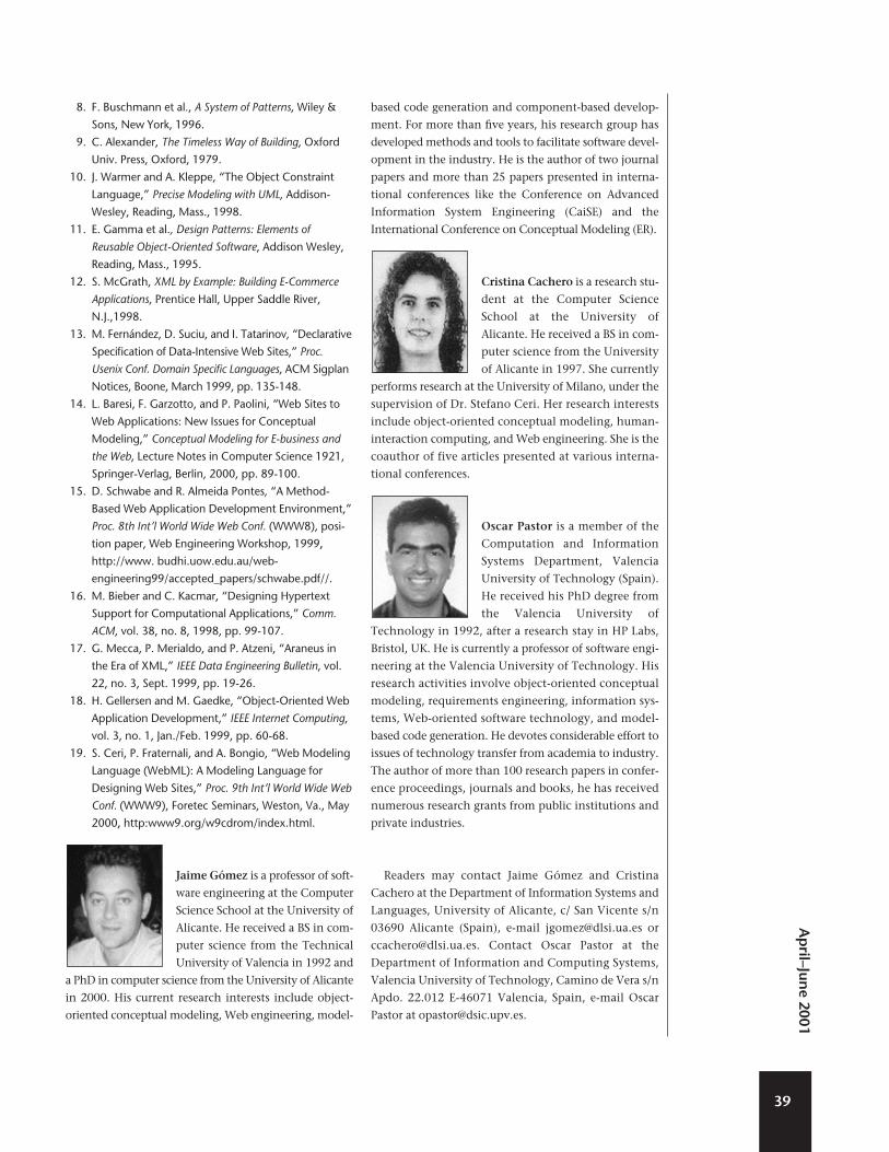
Jaime Gómez is a professor of soft-
ware engineering at the Computer
Science School at the University of
Alicante. He received a BS in com-
puter science from the Technical
University of Valencia in 1992 and
a PhD in computer science from the University of Alicante
in 2000. His current research interests include object-
oriented conceptual modeling, Web engineering, model-
based code generation and component-based develop-
ment. For more than five years, his research group has
developed methods and tools to facilitate software devel-
opment in the industry. He is the author of two journal
papers and more than 25 papers presented in interna-
tional conferences like the Conference on Advanced
Information System Engineering (CaiSE) and the
International Conference on Conceptual Modeling (ER).
Cristina Cachero is a research stu-
dent at the Computer Science
School at the University of
Alicante. He received a BS in com-
puter science from the University
of Alicante in 1997. She currently
performs research at the University of Milano, under the
supervision of Dr. Stefano Ceri. Her research interests
include object-oriented conceptual modeling, human-
interaction computing, and Web engineering. She is the
coauthor of five articles presented at various interna-
tional conferences.
Oscar Pastor is a member of the
Computation and Information
Systems Department, Valencia
University of Technology (Spain).
He received his PhD degree from
the Valencia University of
Technology in 1992, after a research stay in HP Labs,
Bristol, UK. He is currently a professor of software engi-
neering at the Valencia University of Technology. His
research activities involve object-oriented conceptual
modeling, requirements engineering, information sys-
tems, Web-oriented software technology, and model-
based code generation. He devotes considerable effort to
issues of technology transfer from academia to industry.
The author of more than 100 research papers in confer-
ence proceedings, journals and books, he has received
numerous research grants from public institutions and
private industries.
Readers may contact Jaime Gómez and Cristina
Cachero at the Department of Information Systems and
Languages, University of Alicante, c/ San Vicente s/n
03690 Alicante (Spain), e-mail [email protected] or
[email protected]. Contact Oscar Pastor at the
Department of Information and Computing Systems,
Valencia University of Technology, Camino de Vera s/n
Apdo. 22.012 E-46071 Valencia, Spain, e-mail Oscar
Pastor at [email protected].