web: email: … el150u, el150 &el150scpcaxial fans bathroom, toilets, utility rooms and kitchens...
TRANSCRIPT

EL100, EL150U, EL150& EL150SCPC Axial FansBathroom, Toilets, Utility Rooms and Kitchens
Inst
alla
tion
Inst
ruct
ions
Greenwood Air Management Ltd
Greenwood House, Brookside Avenue,
Rustington, West Sussex, BN16 3LF.
Tel: (01903) 771021 Fax: (01903) 782398
Email: [email protected]
Web: www.greenwood.co.uk
Environmental
Slotvent
GW logo col_MASTER
Environmental
Slotvent
Elite Instructions.indd 1 16/01/2012 15:43

32
NOTES:
� Where an open-flued oil or gas- fuelledappliance is installed in the kitchen, extractventilation can cause the spillage of fluegases. Care must be taken to ensureventilation is reduced as appropriate, as setout in the building regulations. The guide tothe regulations suggests that the reducedprovision should be an extract rate 20 l/s (72 m3/h) maximum. Kitchens with solid-fuelappliances should not have extract fans fitted.
� The fans should not be sited where it wouldbe subject to a direct source of heat in excessof 40ºC.
� For window mounting do not install fans inopening windows. Use the correct thicknessof glass for the size of window (at least 4mm thick) if in doubt, contact a glazier.
� A clearance of 75 mm to be allowed on bothsides of fan for the removal of the internalgrille.
Operation
� See Sensor / Timer Adjustments section for further details.
� The Airvac Elite range of fans are fitted with electrical operated anti-backdraughtshutters which have a time delay to open or close.
Read all instructions beforecommencing installations
The Airvac Elite range of fans are single and dual speedaxial flow extract fans designed to exceed BuildingRegulation requirements for bathroom, toilet, kitchen orutility room ventilation.
Types of controls and operation as follows:
TYPE EL100, EL150U, EL150Operation by light switch, remote switch or remote sensor.
TYPE ‘PC’ AND ‘UPC’Operation by pull cord.
TYPE ‘TR’Operation by light switch or remote switch.
When wired into room light or remote switch the fan willoperate whilst the switch is on. Switching off will activatethe overrun timer.
TYPE ‘T’Operation by pull cord, light switch or remote switch.
Integral pull cord will activate the fan for pre-set overruntimer operation. If wired into room light or remote switchthe fan will operate whilst the switch is on. Switching offwill activate the overrun timer.
TYPE ‘DT’Automatic operation by light switch or remote switch.
Pre-set delay timer facility allows up to two minutes offan operation before the overrun timer is actuated. If fanis switched off after the delay timer setting the integraloverrun timer will operate the fan for the pre-set timeperiod.
TYPE ‘HTR’Automatic operation by light switch or remote switch.
The fans integral humidity sensor will operate the fanwhilst the RH exceeds the pre-set activation point, When
the RH is reduced back to the activation point the linkedoverrun timer continues to operate the fan for the pre-settime period to ensure the RH level is further reducedwithin the room to prevent ‘hunting’.
When wired into room light or remote switch the fan willoperate whilst the switch is on. Switching off will activatethe overrun timer.
TYPE ‘PIR’Automatic operation by an integral passive infra-red sensorwhich controls the fan by detecting body movement within7 metres. The sensor picks up the movement and the fanis activated. Once movement ceases the overrun timer willrun for the pre-set time period.
TYPE ‘MA’Dual speed, automatic operation to slow speed andmanual operation to normal speed.
Integral humidistat operates fan to slow speed whilst theRH (relative humidity) exceeds pre-set activation point.When RH is reduced to the pre-set level the linked timercontinues fan at slow speed for the nominated overrunperiod, further lowering the humidity level.
Manual operation by remote switch/light switchoperates the fan at normal speed.
Humidistat adjustable 50 – 90% RH.Adjustable overrun timer (up to 30mins).
TYPE ‘SCPC’Operation by pullcord or remote switch.
Single speed operation at pre-set rate for use whereopen flued gas appliances are present. At installationthe variable speed control is set and sealed to preventspillage from gas appliance.
Elite Instructions.indd 2 16/01/2012 15:43

32
NOTES:
� Where an open-flued oil or gas- fuelledappliance is installed in the kitchen, extractventilation can cause the spillage of fluegases. Care must be taken to ensureventilation is reduced as appropriate, as setout in the building regulations. The guide tothe regulations suggests that the reducedprovision should be an extract rate 20 l/s (72 m3/h) maximum. Kitchens with solid-fuelappliances should not have extract fans fitted.
� The fans should not be sited where it wouldbe subject to a direct source of heat in excessof 40ºC.
� For window mounting do not install fans inopening windows. Use the correct thicknessof glass for the size of window (at least 4mm thick) if in doubt, contact a glazier.
� A clearance of 75 mm to be allowed on bothsides of fan for the removal of the internalgrille.
Operation
� See Sensor / Timer Adjustments section for further details.
� The Airvac Elite range of fans are fitted with electrical operated anti-backdraughtshutters which have a time delay to open or close.
Read all instructions beforecommencing installations
The Airvac Elite range of fans are single and dual speedaxial flow extract fans designed to exceed BuildingRegulation requirements for bathroom, toilet, kitchen orutility room ventilation.
Types of controls and operation as follows:
TYPE EL100, EL150U, EL150Operation by light switch, remote switch or remote sensor.
TYPE ‘PC’ AND ‘UPC’Operation by pull cord.
TYPE ‘TR’Operation by light switch or remote switch.
When wired into room light or remote switch the fan willoperate whilst the switch is on. Switching off will activatethe overrun timer.
TYPE ‘T’Operation by pull cord, light switch or remote switch.
Integral pull cord will activate the fan for pre-set overruntimer operation. If wired into room light or remote switchthe fan will operate whilst the switch is on. Switching offwill activate the overrun timer.
TYPE ‘DT’Automatic operation by light switch or remote switch.
Pre-set delay timer facility allows up to two minutes offan operation before the overrun timer is actuated. If fanis switched off after the delay timer setting the integraloverrun timer will operate the fan for the pre-set timeperiod.
TYPE ‘HTR’Automatic operation by light switch or remote switch.
The fans integral humidity sensor will operate the fanwhilst the RH exceeds the pre-set activation point, When
the RH is reduced back to the activation point the linkedoverrun timer continues to operate the fan for the pre-settime period to ensure the RH level is further reducedwithin the room to prevent ‘hunting’.
When wired into room light or remote switch the fan willoperate whilst the switch is on. Switching off will activatethe overrun timer.
TYPE ‘PIR’Automatic operation by an integral passive infra-red sensorwhich controls the fan by detecting body movement within7 metres. The sensor picks up the movement and the fanis activated. Once movement ceases the overrun timer willrun for the pre-set time period.
TYPE ‘MA’Dual speed, automatic operation to slow speed andmanual operation to normal speed.
Integral humidistat operates fan to slow speed whilst theRH (relative humidity) exceeds pre-set activation point.When RH is reduced to the pre-set level the linked timercontinues fan at slow speed for the nominated overrunperiod, further lowering the humidity level.
Manual operation by remote switch/light switchoperates the fan at normal speed.
Humidistat adjustable 50 – 90% RH.Adjustable overrun timer (up to 30mins).
TYPE ‘SCPC’Operation by pullcord or remote switch.
Single speed operation at pre-set rate for use whereopen flued gas appliances are present. At installationthe variable speed control is set and sealed to preventspillage from gas appliance.
Elite Instructions.indd 3 16/01/2012 15:43

Elite Instructions.indd 4 16/01/2012 15:43

Elite Instructions.indd 5 16/01/2012 15:43

76
1
3
5
8
A
Ø
A
2
4
6
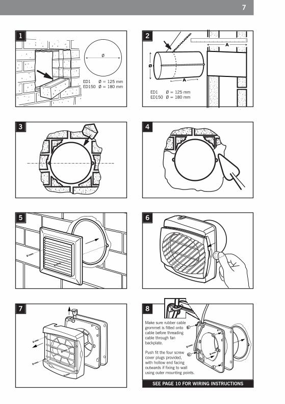
Wall Mounting
SEE PAGE 10 FOR WIRING INSTRUCTIONS
ED1 Ø = 125 mmED150 Ø = 180 mm
ED1 Ø = 125 mmED150 Ø = 180 mm
Ø
EL100/EL150
Ducting
External Grille
7
Make sure rubber cablegrommet is fitted ontocable before threadingcable through fanbackplate.
Push fit the four screwcover plugs provided,with hollow end facingoutwards if fixing to wallusing outer mounting points.
Elite Instructions.indd 6 16/01/2012 15:43
76
1
3
5
8
A
Ø
A
2
4
6
Wall Mounting
SEE PAGE 10 FOR WIRING INSTRUCTIONS
ED1 Ø = 125 mmED150 Ø = 180 mm
ED1 Ø = 125 mmED150 Ø = 180 mm
Ø
EL100/EL150
Ducting
External Grille
7
Make sure rubber cablegrommet is fitted ontocable before threadingcable through fanbackplate.
Push fit the four screwcover plugs provided,with hollow end facingoutwards if fixing to wallusing outer mounting points.
Elite Instructions.indd 7 16/01/2012 15:43

EG1/RAB
Elite Instructions.indd 8 16/01/2012 15:43

Elite Instructions.indd 9 16/01/2012 15:43
1110
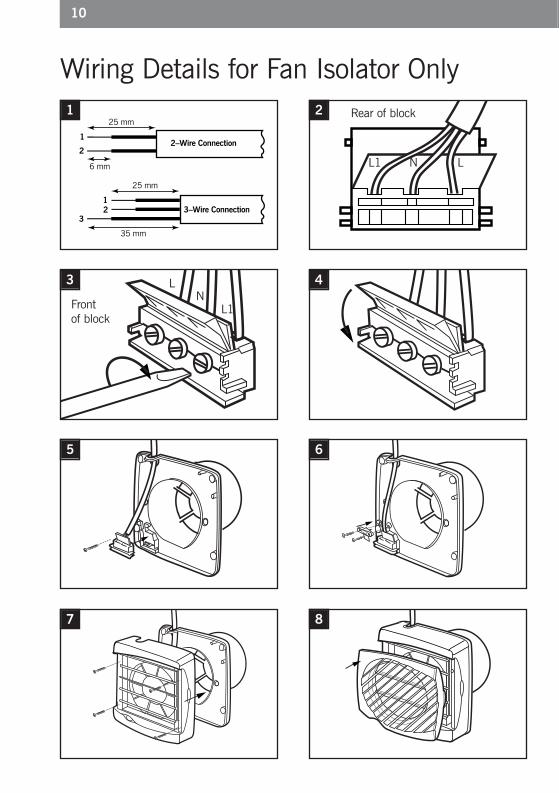
35 mm
25 mm
6 mm
25 mm
3–Wire Connection
2–Wire Connection1
2
12
3
1
3
5
8
2
4
6
Wiring Details for Fan Isolator Only
L
N
L
N
L1
XExternal wiring for remote switch / light switch:Models: EL100, EL150U, EL150 & EL150SCPC
FanTerminalsRemote /
Light Switch
LightOptional
L
NN
L L1
XExternal wiring for pull cord operation in parallelwith room light: Models: T
FanTerminals
L
NN
L L1
XExternal wiring for operation with room light:Models: DT, TR, HTR, UHTR & MA
FanTerminals
XExternal wiring: Model: PIR, PC, UPC & SCPC
1
2L
N 3
FanTerminals
L
N
1
2
3
ControllerTerminals
X
L
N
L
N
L1
FanTerminals
LightSwitch
Light
OperatingSwitch
Light
L
N
L
N
L1
XExternal wiring for remote switch / light switch:Models: EL100, EL150U, EL150 & EL150SCPC
FanTerminalsRemote /
Light Switch
LightOptional
L
NN
L L1
XExternal wiring for pull cord operation in parallelwith room light: Models: T
FanTerminals
L
NN
L L1
XExternal wiring for operation with room light:Models: DT, TR, HTR, UHTR & MA
FanTerminals
XExternal wiring: Model: PIR, PC, UPC & SCPC
1
2L
N 3
FanTerminals
L
N
1
2
3
ControllerTerminals
XExternal wiring: Model: AX150 REV
L
N
L
N
L1
FanTerminals
LightSwitch
Light
OperatingSwitch
Light
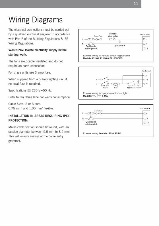
The electrical connections must be carried outby a qualified electrical engineer in accordancewith Part P of the Building Regulations & IEEWiring Regulations.
WARNING: Isolate electricity supply beforestarting work.
The fans are double insulated and do notrequire an earth connection.
For single units use 3 amp fuse.
When supplied from a 5 amp lighting circuitno local fuse is required.
Specification: 230 V~50 Hz.
Refer to fan rating label for watts consumption.
Cable Sizes: 2 or 3 core.0.75 mm2 and 1.00 mm2 flexible.
INSTALLATION IN AREAS REQUIRING IPX4PROTECTION:
Mains cable section should be round, with anoutside diameter between 5.5 mm to 8.5 mm.This will ensure sealing at the cable entrygrommet.
Wiring Diagrams
7
L1 N L
LN
L1
Rear of block
Front of block
Elite Instructions.indd 10 16/01/2012 15:43
1110
35 mm
25 mm
6 mm
25 mm
3–Wire Connection
2–Wire Connection1
2
12
3
1
3
5
8
2
4
6
Wiring Details for Fan Isolator Only
L
N
L
N
L1
XExternal wiring for remote switch / light switch:Models: EL100, EL150U, EL150 & EL150SCPC
FanTerminalsRemote /
Light Switch
LightOptional
L
NN
L L1
XExternal wiring for pull cord operation in parallelwith room light: Models: T
FanTerminals
L
NN
L L1
XExternal wiring for operation with room light:Models: DT, TR, HTR, UHTR & MA
FanTerminals
XExternal wiring: Model: PIR, PC, UPC & SCPC
1
2L
N 3
FanTerminals
L
N
1
2
3
ControllerTerminals
X
L
N
L
N
L1
FanTerminals
LightSwitch
Light
OperatingSwitch
Light
L
N
L
N
L1
XExternal wiring for remote switch / light switch:Models: EL100, EL150U, EL150 & EL150SCPC
FanTerminalsRemote /
Light Switch
LightOptional
L
NN
L L1
XExternal wiring for pull cord operation in parallelwith room light: Models: T
FanTerminals
L
NN
L L1
XExternal wiring for operation with room light:Models: DT, TR, HTR, UHTR & MA
FanTerminals
XExternal wiring: Model: PIR, PC, UPC & SCPC
1
2L
N 3
FanTerminals
L
N
1
2
3
ControllerTerminals
XExternal wiring: Model: AX150 REV
L
N
L
N
L1
FanTerminals
LightSwitch
Light
OperatingSwitch
Light
L
N
L
N
L1
XExternal wiring for remote switch / light switch:Models: EL100, EL150U, EL150 & EL150SCPC
FanTerminalsRemote /
Light Switch
LightOptional
L
NN
L L1
XExternal wiring for pull cord operation in parallelwith room light: Models: T
FanTerminals
L
NN
L L1
XExternal wiring for operation with room light:Models: DT, TR, HTR, UHTR & MA
FanTerminals
XExternal wiring: Model: PIR, PC, UPC & SCPC
1
2L
N 3
FanTerminals
L
N
1
2
3
ControllerTerminals
XExternal wiring: Model: AX150 REV
L
N
L
N
L1
FanTerminals
LightSwitch
Light
OperatingSwitch
Light
L
N
L
N
L1
XExternal wiring for remote switch / light switch:Models: EL100, EL150U, EL150 & EL150SCPC
FanTerminalsRemote /
Light Switch
LightOptional
L
NN
L L1
XExternal wiring for pull cord operation in parallelwith room light: Models: T
FanTerminals
L
NN
L L1
XExternal wiring for operation with room light:Models: DT, TR, HTR, UHTR & MA
FanTerminals
XExternal wiring: Model: PIR, PC, UPC & SCPC
1
2L
N 3
FanTerminals
L
N
1
2
3
ControllerTerminals
XExternal wiring: Model: AX150 REV
L
N
L
N
L1
FanTerminals
LightSwitch
Light
OperatingSwitch
Light
The electrical connections must be carried outby a qualified electrical engineer in accordancewith Part P of the Building Regulations & IEEWiring Regulations.
WARNING: Isolate electricity supply beforestarting work.
The fans are double insulated and do notrequire an earth connection.
For single units use 3 amp fuse.
When supplied from a 5 amp lighting circuitno local fuse is required.
Specification: 230 V~50 Hz.
Refer to fan rating label for watts consumption.
Cable Sizes: 2 or 3 core.0.75 mm2 and 1.00 mm2 flexible.
INSTALLATION IN AREAS REQUIRING IPX4PROTECTION:
Mains cable section should be round, with anoutside diameter between 5.5 mm to 8.5 mm.This will ensure sealing at the cable entrygrommet.
Wiring Diagrams
7
L1 N L
LN
L1
Rear of block
Front of block
External wiring for remote switch / light switch:Models: EL100, EL150 & EL150SCPC
External wiring for operation with room light: Models: TR, HTR & MA
External wiring: Models: PC & SCPC
3 Amp Fuse
3 Amp Fuse
Light optional
Elite Instructions.indd 11 16/01/2012 15:43

12
P570-75 IssD June 2006 05-10-155BP8631
1 2
3
– Timer +– Humid +
4 Model: MA only
6
To clean or service fan� Remove grille: Lever off at side using coin or screwdriver.
� Undo screws (exposed by removal of grille), and pull the fan away from its back plate.
The fan may now be cleaned using a brush or damp cloth. DO NOT IMMERSE IN WATER.
WARNING: On no account should the interior of the fan be cleaned until the unit has beenremoved from its back plate or isolated from the mains.
Sensor/Timer Adjustments
Clockwise to increase and anti-clockwise to decrease timeor humidity sensor sensitivity.
Clockwise to increase and anti-clockwise to decrease time.
90%50%
5 Model: HTR only
Clockwise to increase and anti-clockwise todecrease time or humidity sensor sensitivity.
Model SCPC adjustments, see additional information supplied with fan.
P570-75 IssD June 2008 05-10-155MCR 706 IssE January 2012 05-10-155
Elite Instructions.indd 12 16/01/2012 15:43