web crippling of cold formed steel members
TRANSCRIPT

Missouri University of Science and Technology Missouri University of Science and Technology
Scholars' Mine Scholars' Mine
International Specialty Conference on Cold-Formed Steel Structures
(1998) - 14th International Specialty Conference on Cold-Formed Steel Structures
Oct 15th, 12:00 AM
Web Crippling of Cold Formed Steel Members Web Crippling of Cold Formed Steel Members
K. Prabakaran
R. M. Schuster
Follow this and additional works at: https://scholarsmine.mst.edu/isccss
Part of the Structural Engineering Commons
Recommended Citation Recommended Citation Prabakaran, K. and Schuster, R. M., "Web Crippling of Cold Formed Steel Members" (1998). International Specialty Conference on Cold-Formed Steel Structures. 2. https://scholarsmine.mst.edu/isccss/14iccfsss/14iccfsss-session3/2
This Article - Conference proceedings is brought to you for free and open access by Scholars' Mine. It has been accepted for inclusion in International Specialty Conference on Cold-Formed Steel Structures by an authorized administrator of Scholars' Mine. This work is protected by U. S. Copyright Law. Unauthorized use including reproduction for redistribution requires the permission of the copyright holder. For more information, please contact [email protected].
Fourteenth International Specialty Conference on Cold-Formed Steel Structures St. Louis, Missouri U.S.A., October 15-16,1998
WEB CRIPPLING OF COLD FORMED STEEL MEMBERS
K. Prabakaran1 and R.M. Schuster2
ABSTRACT
A new design expression for web crippling of cold formed steel members has been developed. An extensive statistical analysis was performed using published test data from Canada, the United States, Sweden and France to develop new expressions for the web crippling strength of cold formed steel members under four different loading cases, i.e. (1) end one-flange loading (EOF), (2) mterior one-flange loading (lOF), (3) end two-flange loading (ETF) and (4) interior two-flange loading (lTF). I-sections made of two channels connected back-to-back, Z-sections, channels and multiple web sections (decks) were considered. Comparisons were made with the web crippling expressions presented in the Canadian Standard for the design of cold formed steel structural members, CAN/CSA-S136-M89 (from here on referred to as S136) and with the 1991 LRFD edition of the American Iron and Steel Institute Specification (from here on referred to as AlSI).
The web crippling strength depends primarily on the web thickness (t), the yield strength (Fy), the inside bend radius (r), the bearing length of the load (n), the flat dimension of the web measured in the plane of the web (h) and the angle between the plane of web and the plane of the bearing surface (8). The definition of web depth, h, in both current design standards in Canada (SI36) and the United States (AlSI) was incorporated in the'development of the new expressions. The new developed expression is nondimensional, therefore any consistent units of measurement can be used such as imperial or S1. Certain unnecessary complexities which now exist in both design standards have been removed to simplify the web crippling expressions. Eight simplified new expressions have been 'developed and one particular expression is recommended for design, which has already been adopted by the 1994 edition of S 136.
Graduate Student in Mechanical Engineering at Texas Tech, Lubbock, Texas Formerly a Graduate Student in Civil Engineering, University of Waterloo.
2 Prof_ of Structural Engineering, Department of Civil Engineering, University of Waterloo,
WIterloo. Ontario. Canida. 151
152
INTRODUCTION
The use of cold formed steel members in building construction started in the United States and the United Kingdom at about the same time around 1850, however, their actual real use began in 1940 and the United States led the way in terms ofresearch, application and design. The reason being that cold formed steel members can be produced in many different shapes in a most cost efficient marmer.
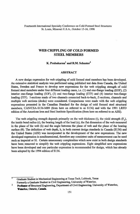
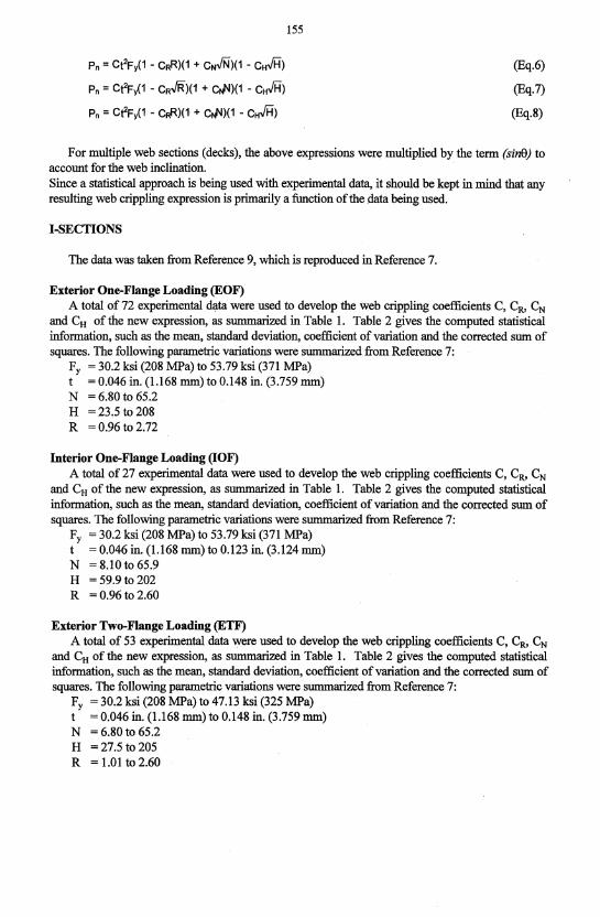
When a cold formed steel member is subjected to load, a concentrated load is normally induced into the web at the point of load application between supports or by way of the reaction at a support. Hence, these loads can cause localized crushing or crippling in the web if the web is relatively thin. Exterior (end) one-flange loading (EOF) or interior one-flange loading (IOF) can be caused by a concentrated load acting on a member at the end (exterior) or somewhere in the middle (interior) of the span. Two-flange loading is experienced if the load is located at the end, exterior two-flange loading (ETF) or in the middle of the span, interior two-flange loading (ITF). See Fig. 1 for schematic illustration of these four load cases.
In addition to these four load cases, the web crippling strength also depends on the web thickness (t), the tensile yield strength (Fy), the inside bend radius (r), the bearing length of the load (n), the flat dimension of the web measured in the plane of the web (h) and the angle between the plane of web and the plane of the bearing surface (8). Therefore, it is clear that a purely theoretical analysis of web crippling under concentrated loading is extremely complex and it is necessary to use experimental test data in the development of any web crippling strength expression.
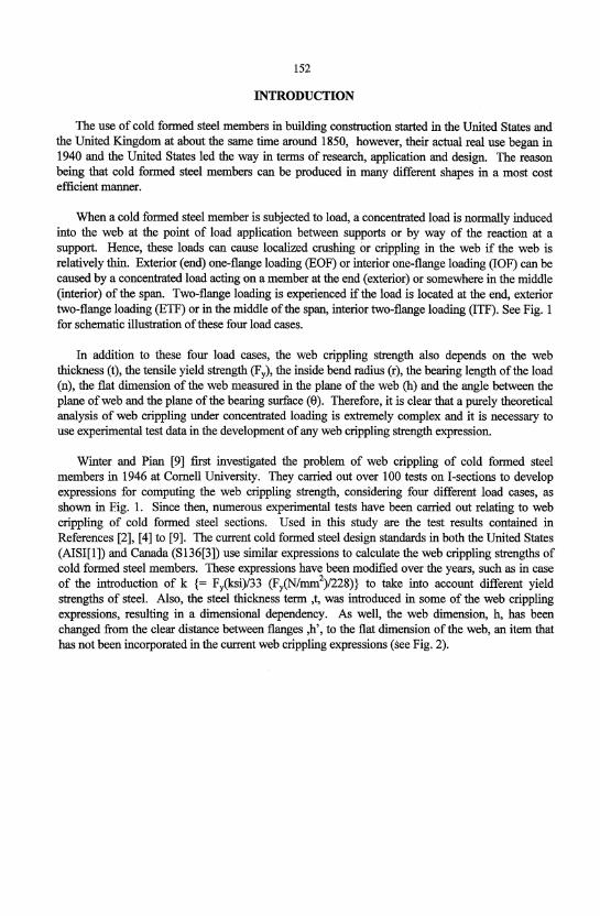
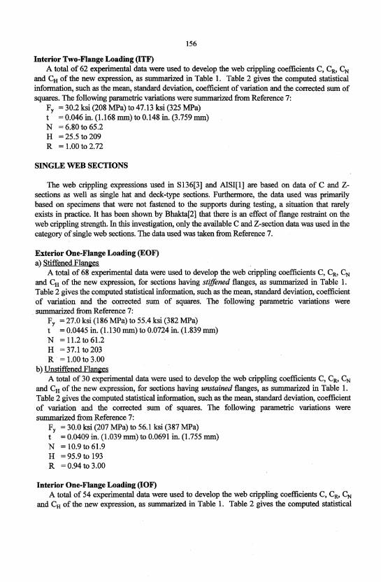
Winter and Pian [9] first investigated the problem of web crippling of cold formed steel members in 1946 at Cornell University. They carried out over 100 tests on I-sections to develop expressions for computing the web crippling strength, considering four different load cases, as shown in Fig. 1. Since then, numerous experimental tests have been carried out relating to web crippling of cold formed steel sections. Used in this study are the test results contained in References [2], [4] to [9]. The current cold formed steel design standards in both the United States (AISI[1]) and Canada (S136[3]) use similar expressions to calculate the web crippling strengths of cold formed steel members. These expressions have been modified over the years, such as in case of the introduction of k {= FyCksi)/33 (Fy(N/mm2)/228)} to take into account different yield strengths of steel. Also, the steel thickness term ,t, was introduced in some of the web crippling expressions, resulting in a dimensional dependency. As well, the web dimension, h, has been changed from the clear distance between flanges ,h', to the flat dimension of the web, an item that has not been incorporated in the current web crippling expressions (see Fig. 2).
153
Failure
(a) Interior One-Flange Loading (lOF) (c) Interior Two-Flange Loading (ITF)
(b) Exterior One-Flange Loading (EOF) (c) Exterior Two-Flange Loading (ETF)
Figure 1: Web Crippling Loading Cases [9]
154
Stiffened Sections
(a) C and Z-Section (b) Multiple Web Section (Deck)
Figure 2: Defmition of Parameter (h)
OBJECTIVE AND SCOPE
The objective of this investigation was to develop a new simplified and totally non-dimensional web crippling expression without the (k) term and incorporating the new definition of (h). Presented in this paper are the results of the fmal recommended design expression which was chosen from eight. possible expressions investigated by Prabakaran[5]. In addition, statistical comparisons were made using the S136[3] and AISl[l] web crippling expressions to substantiate the new recommended design expression.
The study was restricted to the investigation of the web crippling strength of cold formed steel members subjected to web crippling load only, even though in practice most cold formed steel members are subjected to web crippling and bending.
DEVELOPMENT OF NEW EXPRESSION
The following eight web crippling expressions were considered by Prabakaran[5] in the statistical analysis of I-sections, single web and multiple web (deck-type) sections:
Pn = Ct2Fy(1 - CRR)(1 + CJ'I)(1 - ctIi)
Pn = CeFy(1 - cRJR)(1 + ctI'I)(1 - ctIi)
Pn = CeFy(1 • c RJR)(1 + C~)(1 - ctIi)
Pn = CeFy(1 - c RJR)(1 + C~)(1 - cH.JH)
Pn = CeFy(1 - CRR)(1 + c NJi'i)(1 - ctIi)
4
(Eq.l)
(Eq.2)
(Eq.3)
(Eq.4)
(Eq.5)
Pn = Ct2Fy(1 - CRR)(1 + CNJN)(1 - CH.Ji=i)
Pn = CeFy(1 - c R.JR)(1 + cJJ)(1 - cH.JH)
Pn = CeFy(1 - CRR)(1 + CJJ)(1 - cH.JH)
155
(Eq.6)
(Eq.7)
(Eq.8)
For multiple web sections (decks), the above expressions were multiplied by the term (sine) to accmmt for the web inclination. Since a statistical approach is being used with experimental data, it should be kept in mind that any resulting web crippling expression is primarily a function of the data being used.
I-SECTIONS
The data was taken from Reference 9, which is reproduced in Reference 7.
Exterior One-Flange Loading (EOF) A total of 72 experimental data were used to develop the web crippling coefficients C, CR> CN
and CH of the new expression, as summarized in Table 1. Table 2 gives the computed statistical information, such as the mean, standard deviation, coefficient of variation and the corrected sum of squares. The following parametric variations were summarized from Reference 7:
Fy = 30.2 ksi (208 MPa) to 53.79 ksi (371 MPa) t = 0.046 in. (1.168 mm) to 0.148 in. (3.759 mm) N = 6.80 to 65.2 H = 23.5 to 208 R = 0.96 to 2.72
Interior One-Flange Loading (lOF) A total of 27 experimental data were used to develop the web crippling coefficients C, CR> CN
and CH of the new expression, as summarized in Table 1. Table 2 gives the computed statistical information, such as the mean, standard deviation, coefficient of variation and the corrected sum of squares. The following parametric variations were summarized from Reference 7:
Fy = 30.2 ksi (208 MPa) to 53.79 ksi (371 MPa) t = 0.046 in. (1.168 mm) to 0.123 in. (3.124 mm) N = 8.10 to 65.9 H = 59.9 to 202 R = 0.96 to 2.60
Exterior Two-Flange Loading (ETF) A total of 53 experimental data were used to develop the web crippling coefficients C, CR, CN
and CH of the new expression, as summarized in Table 1. Table 2 gives the computed statistical information, such as the mean, standard deviation, coefficient of variation and the corrected sum of squares. The following parametric variations were summarized from Reference 7:
Fy = 30.2 ksi (208 MPa) to 47.13 ksi (325 MPa) t = 0.046 in. (1.168 mm) to 0.148 in. (3.759 mm) N = 6.80 to 65.2 H = 27.5 to 205 R = 1.01 to 2.60
156
Interior Two-Flange Loading (lTF) A total of 62 experimental data were used to develop the web crippling coefficients C, CR, CN
and CH of the new expression, as summarized in Table 1. Table 2 gives the computed statistical information, such as the mean, standard deviation, coefficient of variation and the corrected sum of squares. The following parametric variations were summarized from Reference 7:
Fy = 30.2 ksi (208 MPa) to 47.13 ksi (325 MPa) t = 0.046 in. (1.168 mm) to 0.148 in. (3.759 mm) N = 6.80 to 65.2 H = 25.5 to 209 R = 1.00 to 2.72
SINGLE WEB SECTIONS
The web crippling expressions used in S136[3] and AlSI[I] are based on data of C and Zsections as well as single hat and deck-type sections. Furthermore, the data used was primarily based on specimens that were not fastened to the supports during testing, a situation that rarely exists in practice. It has been shown by Bhakta[2] that there is an effect of flange restraint on the web crippling strength. In this investigation, only the available C and Z-section data was used in the category of single web sections. The data used was taken from Reference 7.
Exterior One-Flange Loading (EOF) a) Stiffened Flalll~es
A total of 68 experimental data were used to develop the web crippling coefficients C, CR, CN
and CH of the new expression, for sections having stiffened flanges, as summarized in Table 1. Table 2 gives the computed statistical information, such as the mean, standard deviation, coefficient of variation and the corrected sum of squares. The following parametric variations were
. summarized from Reference 7: Fy = 27.0 ksi (186 MPa) to 55.4 ksi (382 MPa) t = 0.0445 in. (1.130 mm) to 0.0724 in. (1.839 mm) N = 11.2 to 61.2 H = 37.1 to 203 R . = 1.00 to 3.00
b) Vnstiffened Flanges A total of 30 experimental data were used to develop the web crippling coefficients C, CR, CN
and CH of the new expression, for sections having unstained flanges, as summarized in Table 1. Table 2 gives the computed statistical information, such as the mean, standard deviation, coefficient of variation and the corrected sum of squares. The following parametric variations were summarized from Reference 7:
Fy = 30.0 ksi (207 MPa) to 56.1 ksi (387 MPa) t = 0.0409 in. (1.039 mm) to 0.0691 in. (1.755 mm) N = 10.9 to 61.9 H = 95.9 to 193 R = 0.94 to 3.00
Interior One-Flange Loading (lOF) A total of 54 experimental data were used to develop the web crippling coefficients C, CR, CN
and CH of the new expression, as summarized in Table 1. Table 2 gives the computed statistical
157
infonnation, such as the mean, standard deviation, coefficient of variation and the corrected sum of squares. The following parametric variations were summarized from Reference 7:
Fy = 30.9 ksi (213 MPa) to 55.8 ksi (385 MPa) t = 0.0475 in. (1.207 mm) to 0.0669 in. (1.699 mm) N = 11.3 to 62.5 H = 83.1 to 203 R = 0.96 to 3.00
Exterior Two-Flange Loading (ETF) A total of 26 experimental data were used to develop the web crippling coefficients C, CR, CN
and CH of the new expression, as summarized in Table 1. Table 2 gives the computed statistical infonnation, such as the mean, standard deviation, coefficient of variation and the corrected sum of squares. The following parametric variations were summarized from Reference 7:
Fy = 36.26 ksi (250 MPa) to 47.12 ksi (325 MPa) t = 0.0460 in. (1.168 mm) to 0.0515 in. (1.308 mm) N = 19.4 to 63.2 H = 90.0 to 208 R = 0.96 to 2.72
Interior Two-Flange Loading (ITF) A total of 26 experimental data were used to develop the web crippling coefficients C, CR, CN
and CH of the new expression, as summarized in Table 1. Table 2 gives the computed statistical infonnation, such as the mean, standard deviation, coefficient of variation and the corrected sum of squares. The following parametric variations were summarized from Reference 7:
Fy = 36.26 ksi (250 MPa) to 47.12 ksi (325 MPa) t = 0.0470 in. (1.194 mm) to 0.0522 in. (1.326 mm) N = 19.3 to 63.8 H = 88.8 to 205 R = 0.95 to 2.66
MULTIPLE WEB SECTIONS (DECKS)
This category exists only in 8136[3] and not in A18I[I]. The data used was taken primarily from Reference 8. Exterior One-Flange Loading (EOF)
Only four experimental data for restrained flanges were used to develop the web crippling coefficients C, CR, CN and CH of the new expression, as summarized in Table 1. Table 2 gives the computed statistical infonnation, such as the mean, standard deviation, coefficient of variation and the corrected sum of squares. The following parametric variations were summarized from Reference 8:
I'y = 43.82 ksi (302 MPa) to 57:49 ksi (396 MPa) t = 0.0260 in. (0.660 mm) to 0.0490 in. (1.245 mm) N = 53.6 to 101 H = 89.6 to 137 R =4.14t06.62 e =900
158
Interior One-Flange Loading (lOF) A total of 90 experimental data were used to develop the web crippling coefficients C, CR, CN
and CH of the new expression, as summarized in Table 1. Table 2 gives the computed statistical information, such as the mean, standard deviation, coefficient of variation and the corrected sum of squares. The following parametric variations were summarized from Reference 8:
Fy = 30.9 ksi (213 MPa) to 55.8 ksi (385 MPa) t = 0.0216 in. (0.549 mm) to 0.0669 in. (1.699 mm) N = 11.3 to 208 H = 62.1 to 209 R = 1.00 to 17.4 e = 50° to 90°
Exterior Two-Flange Loading (ETF) A total of 80 experimental data were used to develop the web crippling coefficients C, CR, CN
and CH of the new expression, as summarized in Table 1. Table 2 gives the computed statistical information, such as the mean, standard deviation, coefficient of variation and the corrected sum of squares. The following parametric variations were summarized from Reference 8:
Fy = 33.5 ksi (231 MPa) to 49.0 ksi (338 MPa) t = 0.0240 in. (0.610 mm) to 0.0620 in. (1.575 mm) N = 16.4 to 125 H = 21.4.to 328 R = 1.34 to 10.1 e =45° to 90°
Interior Two-Flange Loading (lTF) A total of 82 experimental data were used to develop the web crippling coefficients C, CR, CN
and CH of the new expression, as summarized in Table 1. Table 2 gives the computed statistical information, such as the mean, standard deviation, coefficient of variation and the corrected sum of squares. The following parametric variations were summarized from Reference 8:
Fy = 33.5 ksi (231 MPa) to 49.0 ksi (338 MPa) t = 0.0240 in. (0.610 mm) to 0.0606m. (1.539 mm) N = 16.7 to 125 H = 21.4 to 209 R = 1.34 to 10.1 e = 45° to 90.5°
CONCLUSIONS
An extensive statistical web crippling investigation of cold formed steel sections was carried out, using the experimental data available in the literature. The object of this study was to develop a new simplified and consistent expression for the prediction of the web crippling strength of cold formed steel members, which has been accomplished.
Based on the results of this research, Expression 4 is recommended for the design of I -sections, single web sections and multiple web sections (decks). The new expression is presented in Table 1 with the corresponding web crippling coefficients for the four typical load cases of end one flange loading (EOF), interior one flange loading (lOF), end two flange loading (ETF) and interior two flange loading (lTF).
159
The parameter limits are based on the test data used and should remain as presently specified in S136 [1], i.e.,
a) for I-sections and shapes having single webs are H < 200, N < 200, nih < 1 and R < 4 and b) for multiple web sections (decks) H <200, N <200, nih <2 andR < 10.
The statistical results of the recommended Expression 4 are given in Table 2. As can be observed, th~ statistical parameters are within the range of those found when using AISI[I] - see Table 3 and S136[3] - see Table 4. The recommended Expression 4 has already been adopted in the 1994 edition of S136. Since the time of this work, additional data has been generated by Cain and LaBoube at the University of Missouri-Rolla. This data should also be included in a follow-up statistical evaluation in the future.
REFERENCES
1. American Iron and Steel Institute, LRFD Cold, Formed Steel Design Manual, Part 1-Specification and Part II-Commentary, Washington, D.C., 1991.
2. Bhakta, B.H., "The Effect of Flange Restraint on Web Crippling Strength." M.A.Sc. Thesis, University of Missouri-Rolla, U.S.A., 1992.
3. CAN/CSA-SI36-M89, Cold Formed Steel Structural Members, Canadian Standards Association, Rexdale (Toronto), Ontario, Canada, 1989.
4. Hetrakul, N., and Yu, W.W., "Structural Behavior of Beam Webs Subjected to Web Crippling and a Combination of Web Crippling and Bending." Final Report, Civil Engineering Study 78-4, University of Missouri-Rolla, U.S.A., June 1978.
5. Prabakaran, K., "Web Crippling of Cold Formed Steel Sections." M.A.Sc. Thesis, University of Waterloo, Ontario, Canada, 1993.
6. Santaputra, C., Parks, M.B., and Yu, W.W., "Web Crippling Strength of Cold Formed Steel Beams." Journal of Structural Engineering, ASCE, Vol. 115, No. 10, October 1989.
7. Supornsilaphachai, B., Galambos, T.V., and Yu, W.W., "Load and Resistance Factor Design of Cold-formed Steel." Fifth Progress Report, Department of Civil Engineering, University of Missouri-Rolla, U.S.A., September 1979.
8. Wmg, B.A., "Web Crippling and the Interaction ofBending and Web Crippling of Unreinforced Multi-Web Cold Formed Steel Sections." M.A.Sc. Thesis, University of Waterloo, Ontario, Canada, 1981.
9. Winter, G., and Pian, R.H.J., "Crushing Strength of Thin Steel Webs." Cornell Bulletin No. 35, Part 1, Engineering Experiment Station, Cornell University, U.S.A., April 1946.
C CH
CN CR
C.S.S. C.V. EOF ETF Fy h H IOF ITF k n N P Pa
Pn
Ps
Pt
r R S.D. SI t 8
160
NOTATIONS
coefficient web slenderness coefficient bearing length coefficient inside bend radius coefficient corrected sum of squares coefficient of variation exterior one-flange loading exterior two-flange loading yield strength of steel flat dimension of web measured in the plane of the web web slenderness ratio, hit interior one-flange loading interior two-flange loading F/33 (ksi) ; Fy 1228 (N/mm2)
bearing length of load bearing length to thickness ratio, nit applied load per web computed ultimate web crippling load per web using AISI [1] expression computed ultimate web crippling load or reaction per web using new expression computed ultimate web crippling load per web using S136 [3] expression test ultimate web crippling load per web inside bend radius inside bend radius to thickness ratio, rlt standard deviation system international web thickness angle between plane of web and plane of bearing surface in degrees
161
TABLE! RECOMMENDED EXPRESSION
Pn = CeFy(sin8)(1 - cRJR)(1 + cNJN)(1 - cH.JH) (Eq.4)
C CR CN CH
I-SECTIONS
a) EOF 9.85 0.185 0.315 0.001 b) IOF 18.0 0.001 0.075 0.001 c) ETF 15.0 0.001 0.100 0.050 d) ITF 28.0 0.001 0.035 0.025
SINGLE WEB SECTIONS
a) EOF i) Stiffened
Flanges ii) Unstiffened 4.00 0.230 0.650 0.035
Flanges b) IOF 7.20 0.250 0.120 0.030 c) ETF 17.0 0.130 0.130 0.040 d) ITF 17.0 0.400 0.064 0.045
29.5 0.135 0.080 0.060
MULTIPLE WEB SECTIONS (DECKS)
a) EOF 4.00 0.070 0.200 0.001 b) IOF 21.0 0.120 0.065 0.040 c) ETF 9.00 0.180 0.200 0.044 d) ITF 10.0 0.140 0.210 0.020
Note: See FIg. 1 for descrIptIOn of EOF, IOF, ETF, ITF. Expression 4 applies to I-sections and single web sections when R<4, N<200, H<200 and n/h<l. Expression 4 applies to multipleweb sections when R<lO, N<200, H<200 and n/h<2.
162
TABLE 2
STATISTICAL RESULTS OF RECOMMENDED EXPRESSION
GIVEN IN TABLE 1
MEAN S.D. C.V. C.S.S. Tests Used 1 OF PlPn OF PlPn OFPlPn OFPlPn Total Tests
I-SECTIONS
a) EOF 1.073 0.215 0.200 3.095 68/72 b) IOF 1.035 0.168 0.162 0.649 24/27 c) ETF 1.044 0.245 0.235 3.127 53153 d) ITF 1.048 0.221 0.211 2.790 58/62
SINGLE WEB SECTIONS
a) EOF i) Stiffened
Flanges 1.000 0.122 0.121 0.944 65168 ii) Unstiffened
Flanges 1.096 0.247 0.225 1.763 30/30 b) IOF 1.095 0.140 0.128 1.025 53/54 c) ETF 1.000 0.061 0.061 0.079 22/26 d) ITF 1.072 0.081 0.075 0.137 22/26
MULTIPLE WEB SECTIONS (DECKS)
a) EOF 1.073 0.017 0.016 0.001 4/4 b) IOF 1.023 0.167 0.163 2.151 78/90 c) ETF 1.046 0.166 0.159 1.900 70/80 d) ITF 1.078 0.143 0.133 1.558 77/82
Note: See Fig. 1 for descrrptlOn of EOF, IOF, ETF, ITF. Where PI = ultimate test web crippling load per web
P n = ultimate computed web crippling load per web using the parameters of Expression 4 given in Table 1.
163
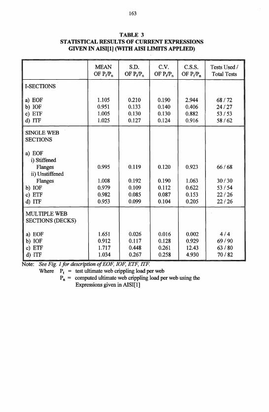
TABLE 3 STATISTICAL RESULTS OF CURRENT EXPRESSIONS
GIVEN IN AISI[l) (WITH AISI LIMITS APPLIED)
MEAN S.D. C.V. C.S.S. OFPlPn OFPlPn OF PlPn OFPlPn
I-SECTIONS
a) EOF 1.105 0.210 0.190 2.944 b) lOF 0.951 0.133 0.140 0.406 c) ETF 1.005 0.130 0.130 0.882 d) ITF 1.025 0.127 0.124 0.916
SINGLE WEB SECTIONS
a) EOF i) Stiffened
Flanges 0.995 0.119 0.120 0.923 ii) Unstiffened
Flanges 1.008 0.192 0.190 1.063 b) IOF 0.979 0.109 0.112 0.622 c) ETF 0.982 0.085 0.087 0.153 d) ITF 0.953 0.099 0.104 0.205
MULTIPLE WEB SECTIONS (DECKS)
a) EOF 1.651 0.026 0.016 0.002 b) lOF 0.912 0.117 0.128 0.929 c) ETF 1.717 0.448 0.261 12.43 d) ITF 1.034 0.267 0.258 4.930
Note: See Fig. 1 for desCrlptwn of EOF, IOF, ETF, ITF. Where Pt = test ultimate web crippling load per web
P n = computed ultimate web crippling load per web using the Expressions given in AlSI[1)
Tests Used 1 Total Tests
68/72 24/27 53/53 58/62
66/68
30/30 53/54 22/26 22/26
4/4 69190 63/80 70/82
164
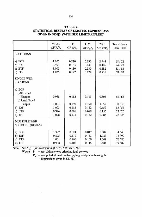
TABLE 4 STATISTICAL RESULTS OF EXISTING EXPRESSIONS
GIVEN IN S136[3] (WITH S136 LIMITS APPLIED)
MEAN S.D. C.V. C.S.S. OFp/Pn OF P!l'n OF PlPn OFp/Pn
I-SECTIONS
a) EOF 1.105 0.210 0.190 2.944 b) IOF 0.951 0.133 0.140 0.406 c) ETF 1.005 0.130 0.130 0.882 d) ITF 1.025 0.127 0.124 0.916
SINGLE WEB SECTIONS
a) EOF i) Stiffened
Flanges 0.988 0.112 0.113 0.803 ii) Unstiffened
Flanges 1.003 0.190 0.190 1.052 b) IOF 1.003 0.112 0.112 0.652 c) ETF 0.974 0.086 0.089 0.156 d) ITF 1.028 0.135 0.132 0.385
MULTIPLE WEB SECTIONS (DECKS)
a) EOF 1.397 0.024 0.017 0.002 b) IOF 0.895 0.119 0.133 1.083 c) ETF 1.001 0.160 0.159 1.748 d) ITF 0.938 0.108 0.115 0.881
Note: See FIg. 1 for deSCrIptIOn of EOF, lOF, ETF, ITF. Where PI = test ultimate web crippling load per web
P n = computed ultimate web crippling load per web using the . Expressions given in S136[3]
Tests Used/ Total Tests
68/72 24/27 53/53 58/62
65/68
30/30 53/54 22/26 22/26
4/4 78/90 70/80 77/82