web based robotics
TRANSCRIPT

8/3/2019 Web Based Robotics
http://slidepdf.com/reader/full/web-based-robotics 1/52
WEB BASED TELEMATICS APPLICATION FOR
ROBOTICS
A P R O J E C T R E P O R T
S u b m i t t e d b y
P R A D E E S H . P . K
R A K E S H K R I S H A N . P
A N O J . R . S
S U J I T H M O H A N . M
i n p a r t i a l f u l f i l l m e n t f o r t h e a w a r d o f t h e d e g r e e
o f
B A C H E L O R O F E N G I N E E R I N G
i n
E L E C T R O N I C S A N D C O M M U N I C A T I O N
E N G I N E E R I G
U D A Y A S C H O O L O F E N G I N E E R I N G , V E L L A M O D I .
A N N A U N I V E R S I T Y : C H E N N A I 6 0 0 0 2 5
A P R I L 2 0 1 0
1
8/3/2019 Web Based Robotics
http://slidepdf.com/reader/full/web-based-robotics 2/52
ANNA UNIVERSITY: CHENNAI 600 025
BONAFIDE CERTIFICATE
This is to certify that the project report ” W E B B A S E D
T E LE M AT I CS A P PL I CA T IO N F O R R OB O TI C S” i s t h e
b o na f id e w or k o f “ ** * ** ” w h o c a rr i ed o ut t h e p r o j ec t
w o r k u n d e r m y s u p e r v i s i o n.
SIGNATURE SIGNATURE
MRS.N.VIDHYA LEKSHMI M.Tech MR.N.SATHEESH KUMAR M.E
HEAD OF THE DEPARTMENT, SUPERVISOR,
Electronics and Communication Electronics and Communication
Engineering, Engineering,
Udaya School Of Engineering, Udaya School Of Engineering,
Vellamodi-629 204. Vellamodi-629 204.
EXTERNAL EXAMINER INTERNAL EXAMINER
2

8/3/2019 Web Based Robotics
http://slidepdf.com/reader/full/web-based-robotics 3/52
TABLE OF CONTENTS
CHAPTER TITLE PAGE NO
ABSTRACT 5
1. INTRODUCTION 5
1.1 Block Diagram 61.2 Circuit Diagram 6
2. HARDWARE DESCRIPTION
2.1 Introduction 7
2.2 Description 7
2.2.1 Memory Unit 8
2.2.2 Central Processing Unit 9
2.2.3 Input Output Unit 10
2.2.4 Serial communication 11
2.2.5 Timer Unit 13
2.2.6 AT89C52 MICROCONTROLLER 14
2.2.7 Description 14
2.2.8 Special Function Registers 15
3. MICROCONTROLLER INTERFACING
3.1 DC Motor
3.1.1 Introduction 16
3.1.2 Theory of DC motor speed control 17
3
8/3/2019 Web Based Robotics
http://slidepdf.com/reader/full/web-based-robotics 4/52
3.1.3 Speed Sensing Mechanism 18
3.1.4 Speed Encoders 20
3.1.5 Working Theory of H-Bridge 22
3.1.6 L293D Dual H-Bridge Motor Driver 23
3.2 RS232 serial connector pin assignment 25
3.3 Ultrasonic Sensor
4. DESCRIPTION OF DEVELOPMENT SYSTEM
4.1 Cross Compilers 26
4.1.1 Introduction to Keil 26
4.1.2 Functioning of Keil 27
4.1.3 Development tools in keil 27
4.1.4 C51 Optimizing C Cross Compiler 28
4.1.5 A51 Macro Assembler 29
4.1.6 BL51 Code Banking Linker/Locator 30
4.1.7 OC51 banked object file converter 30
4.1.8 OH51 object hex converter 30
4.1.9 µVISION/51 FOR WINDOWS 31
4.2 TARGET PROCESSOR 32
5. APPLICATION SOFTWARE
5.1 Application software description 35
5.2 Screen Shots 36
6. CONCLUTIONS 37
4

8/3/2019 Web Based Robotics
http://slidepdf.com/reader/full/web-based-robotics 5/52
ABSTRACT
In this project an obstacle sensing and object guiding Robot is
designed. Major problem in robot design is to detect an obstacle in front of it
to avoid collision. In this project, an electronic solution is attempted for this
problem. We use a pair of ultrasonic sensor acting as an artificial eye for the
robot. The ultrasonic transmitter would transmit the ultrasonic wave from
the robot. Incase the robot meet an obstacle within the specific range from
the transmitter, the reflected waves are sensed by the ultrasonic receiver
which is placed at the close proximity of the transmitter. The system will
have an amplifier which would amplify this received signal and fire an
interrupt signal to the Embedded Microcontroller. The Embedded
microcontroller would then fire a warning alarm to the robot enabling the
user to take necessary diversion to avoid collision. This project is of
immense use in the autonomous robot designs to avoid collisions with the
obstacles. The obstacle information is transmitted to a client PC using serial
communication and full control of the Rot to the user in the server PC.
5

8/3/2019 Web Based Robotics
http://slidepdf.com/reader/full/web-based-robotics 6/52
LIST OF TABLES
TABLE TITLE PAGE
NO. NO.
6

8/3/2019 Web Based Robotics
http://slidepdf.com/reader/full/web-based-robotics 7/52
LIST OF FIGURES
FIGURE TITLE PAGE
NO. NO.
7

8/3/2019 Web Based Robotics
http://slidepdf.com/reader/full/web-based-robotics 8/52
1. INTRODUCTION
In this project an obstacle sensing and object guiding Robot is
designed. Major problem in robot design is to detect an obstacle in front of it
to avoid collision. In this project, an electronic solution is attempted for this problem. We use a pair of ultrasonic sensor acting as an artificial eye for the
robot. The ultrasonic transmitter would transmit the ultrasonic wave from
the robot. Incase the robot meet an obstacle within the specific range from
the transmitter, the reflected waves are sensed by the ultrasonic receiver
which is placed at the close proximity of the transmitter. The system will
have an amplifier which would amplify this received signal and fire an
interrupt signal to the Embedded Microcontroller.
The Embedded microcontroller would then fire a warning alarm to
the robot enabling the user to take necessary diversion to avoid collision.
This project is of immense use in the autonomous robot designs to avoid
collisions with the obstacles. The obstacle information is transmitted to a
client PC using serial communication and full control of the Robot to the
user in the server PC. A pair of dc servo motor drives the robot towards the
target.
8

8/3/2019 Web Based Robotics
http://slidepdf.com/reader/full/web-based-robotics 9/52
1.1 BLOCK DIAGRAM:
Embedded
Processor
Reset
Hardware
Oscillator
Hardware
Power
PC
Interface
RS232
Ultrasonic
Transducer
Motor
Driver
Motor
1
Motor
2
NIC
9

8/3/2019 Web Based Robotics
http://slidepdf.com/reader/full/web-based-robotics 10/52
1.2 CIRCUIT DIAGRAM:
Fig 1.1 PROJECT SCHEMATIC DIAGRAM
10

8/3/2019 Web Based Robotics
http://slidepdf.com/reader/full/web-based-robotics 11/52
1.2. ULTRASONIC SENSOR
11
8/3/2019 Web Based Robotics
http://slidepdf.com/reader/full/web-based-robotics 12/52
2. HARDWARE DESCRIPTION
2.1 INTRODUCTION TO TARGET PROCESSOR
Microcontroller differs from a microprocessor in many ways. First
and the most important is its functionality. In order for a microprocessor to be
used, other components such as memory, or components for receiving and
sending data must be added to it. In short that microprocessor is the very heart
of the computer. On the other hand, microcontroller is designed to be all of that in one. No other external components are needed for its application
because all necessary peripherals are already built into it. Thus , we save
the time and space needed to construct devices .this chapter deals
with the study of microcontrollers.
2.2 DESCRIPTION TO EMBEDDED CONTROLLERS
Microcontroller, as the name suggests, are small controllers. These arelike single chip computers that are often embedded into systems to function as
processing /controllers unit. For example, the remote control you are using
probably has microcontrollers inside that do decoding and other controlling
functions. They are also used in automobiles, washing machines, microwave
ovens, toys…etc, where automation is needed. The key features of
microcontrollers include:
• High integration of Functionality
Microcontrollers sometimes are called single chip computers because they have on-chip memory and I/O circuitry and other
circuitries that enable them to function as small standalone
computers without other supporting circuitry.
• Field Programmability, Flexibility
Microcontrollers often use EEPROM or EPROM as their storage
device to allow field programmability so they are flexible to use. Once the
12
8/3/2019 Web Based Robotics
http://slidepdf.com/reader/full/web-based-robotics 13/52
program is tested to be correct then large quantities of microcontrollers can
be programmed to be used in embedded systems.
• Easy to Use
Assembly language is often used in microcontroller and since they
usually follow RISC architecture, the instruction set is small. The
development package of microcontrollers often includes an assembler ,a
simulator ,a programmer to “ burn “ the chip and a demonstration board
.Some packages include a high level language compiler such as a C
compiler and more sophisticated libraries.
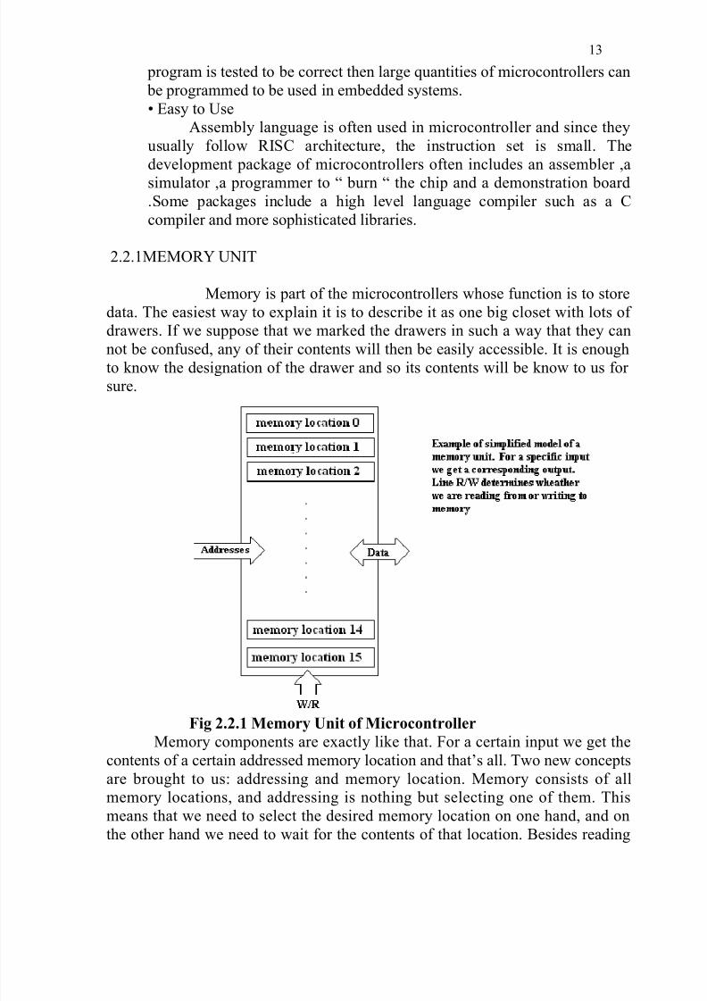
2.2.1MEMORY UNIT
Memory is part of the microcontrollers whose function is to store
data. The easiest way to explain it is to describe it as one big closet with lots of
drawers. If we suppose that we marked the drawers in such a way that they can
not be confused, any of their contents will then be easily accessible. It is enoughto know the designation of the drawer and so its contents will be know to us for
sure.
Fig 2.2.1 Memory Unit of Microcontroller
Memory components are exactly like that. For a certain input we get the
contents of a certain addressed memory location and that’s all. Two new concepts
are brought to us: addressing and memory location. Memory consists of all
memory locations, and addressing is nothing but selecting one of them. This
means that we need to select the desired memory location on one hand, and on
the other hand we need to wait for the contents of that location. Besides reading
13

8/3/2019 Web Based Robotics
http://slidepdf.com/reader/full/web-based-robotics 14/52
from a memory location, memory must also provide for writing onto it. This is
done by supplying an additional line called control line. We will designate this
line as R/W (read/write). Control line used in the following way: if r/w=1,
reading is done, and if opposite is true then writing is done on the memory
location. Memory is the first element, and we need a few operation of our
microcontroller.
2.2.2 CENTRAL PROCESSING UNIT
Let add three memory locations to a specific block that will have a built in
capability to multiply, divide, subtract, and move its contents from one memory
location onto another. The part we just in is called “Central Processing Unit”
(CPU). Its memory locations are called registers.
Fig 2.2.2 Central Processing Unit of Microcontroller
Registers are therefore memory locations whose role is to help with
performing various mathematical operations or any other operations with datawherever data can be found. Look at the current situation. We have two
independent entities (memory and CPU) which are interconnected, and thus any
exchange of data is hindered, as well as its functionality. If, for example, we wish
to add the contents of two memory locations and return the result again back to
memory, we would need a connection between memory and CPU. Simply stated,
we must have some “way” though data goes from one block to another.
14
8/3/2019 Web Based Robotics
http://slidepdf.com/reader/full/web-based-robotics 15/52
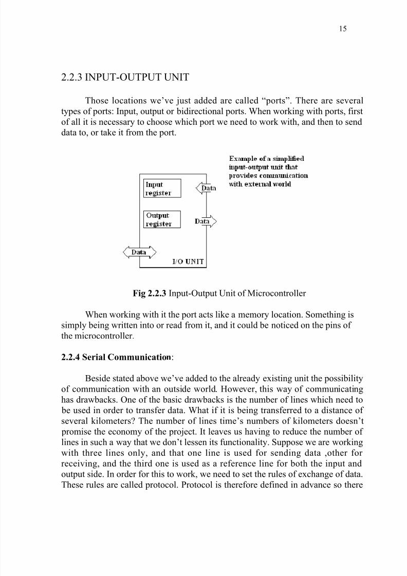
2.2.3 INPUT-OUTPUT UNIT
Those locations we’ve just added are called “ports”. There are severaltypes of ports: Input, output or bidirectional ports. When working with ports, first
of all it is necessary to choose which port we need to work with, and then to send
data to, or take it from the port.
Fig 2.2.3 Input-Output Unit of Microcontroller
When working with it the port acts like a memory location. Something is
simply being written into or read from it, and it could be noticed on the pins of
the microcontroller.
2.2.4 Serial Communication:
Beside stated above we’ve added to the already existing unit the possibility
of communication with an outside world. However, this way of communicating
has drawbacks. One of the basic drawbacks is the number of lines which need to be used in order to transfer data. What if it is being transferred to a distance of
several kilometers? The number of lines time’s numbers of kilometers doesn’t
promise the economy of the project. It leaves us having to reduce the number of
lines in such a way that we don’t lessen its functionality. Suppose we are working
with three lines only, and that one line is used for sending data ,other for
receiving, and the third one is used as a reference line for both the input and
output side. In order for this to work, we need to set the rules of exchange of data.
These rules are called protocol. Protocol is therefore defined in advance so there
15

8/3/2019 Web Based Robotics
http://slidepdf.com/reader/full/web-based-robotics 16/52
wouldn’t be any misunderstanding between the sides that are communicating
with each other. The logical unit “1” is set up on the transmitting line until
transfer begins. Once the transfer starts, we lower the transmission line to logical
‘0” for a period of time (which we will designate as T), so the receiving side will
know that it is receiving data, and so it will activate its mechanism for reception.
Let’s go back now to the transmission side and start putting logic zeros and ones
the transmitter line in the order from a bit of the lowest value to a bit of the
highest value. Let each bit stay on line for a time period which is equal to T, and
in the end, or after the 8th bit. Let us bring the logical unit “1” back on the line
which will mark the end of the transmission of one data. The protocol we’ve just
described is called in professional literature NRZ (Non-Return to Zero).
Fig 2.2.4 Serial Communication
As we have separate lines for receiving and sending, it is possible to
receiving and sends data at the same time. So called full-duplex mode block
which enables this way of communication is called a serial communication block.
Unlike the parallel transmission, data moves here bit by bit, or in a series of bits
what defines the term serial communication comes from. After the reception of
data we need to read it from the receiving location and store it in memory as
opposed to sending where the process is reversed. Data goes from memory
through the buys to the sending location, and then to the receiving unit according
unit according to the protocol.
2.2.5 TIMER UNIT
Since we have the serial communication explained, we can receive, send
and Process data.
16

8/3/2019 Web Based Robotics
http://slidepdf.com/reader/full/web-based-robotics 17/52
Fig 2.2.5 Timer
However, in order to utilize it in industry we need a few additionally
blocks. One of those is the timer block which is significant to us because it can
give us information about time, duration, protocol etc. The basic unit of the timer
is a free-run counter which is in fact a register whose numeric value increments by one in even intervals, so that by taking its value during periods T1 and T2 and
on the basis of their difference we can determine how much time has elapsed.
This is a very important part of the microcontroller whose understanding requires
most of our time.
2.2.6 FEATURES OF AT89C52 MICROCONTROLLER (TARGET
PROCESSOR)
AT89C52 is a slightly more powerful microcontroller which provides highly
flexible and cost effective solutions to many embedded control applications.
Following are the features.
1. It has 256 bytes of internal RAM compared to 128 in the standard
8051.
2. It is low power; high performance CMOS 8-bit microcomputers with
8K bytes of flash programmable and erasable read only memory
(PEROM).
3. Fully static operation: 0 Hz to 24 MHz.4. It has 32 programmable I/O lines i.e. it has 4 ports (port0 to port3)
with 8 lines each.
5. A third 16-bit Timer/counter is present inside this microcontroller to
strengthen its operation, compared to only 2 timers in standard 8051.
6. It has eight interrupt sources.
7. One more additional feature of AT89C52 is that it has 26 special
function registers, 5 more than the standard 8051.
17
8/3/2019 Web Based Robotics
http://slidepdf.com/reader/full/web-based-robotics 18/52
8. The device is manufactured using ATMEL’s high-density non volatile
memory technology and is compatible with the industry-standard
80C51 and 80C52 instruction set and pin out.
2.2.7 DESCRIPTION
The AT89C52 is a low-power, high-performance CMOS 8-bit
microcomputer with 8K bytes of Flash programmable and erasable
read only memory (PEROM). The device is manufactured using
Atmel’s high-density nonvolatile memory technology and is
compatible with the industry-standard 80C51 and 80C52 instruction
set and pin out. The on-chip Flash allows the program memory to be
reprogrammed in-system or by a conventional nonvolatile memory
programmer. By combining a versatile 8-bit CPU with flash on a
monolithic chip, the Atmel AT89C52 is a powerful microcomputer
which provides a highly-flexible and cost-effective solution to manyembedded control applications.
The AT89C52 provides the following standard features: 8K
bytes of flash, 256 bytes of RAM, 32 I/O lines three 16-bit
timer/counters, a six-vector two level interrupt architecture, a full
serial-duplex serial port, on-chip oscillator, and clock circuitry. In
addition, the AT89C52 is designed with static logic for operation
down to zero frequency and supports two software selectable power
saving modes. The Idle Mode stops the CPU while allowing RAM,
timer/counters, serial port, and interrupt system to continue
functioning. The Power-down mode saves the RAM contents but
freezes the oscillator, disabling all other chip functions until the next
hardware reset.
2.2.8 SPECIAL FUNCTION REGISTERS
A map of the on-chip memory area called the Special Function Register
(SFR) space is shown in table 1.
Note that not all of the addresses are occupied, and unoccupied addressesmay not be implemented on the chip. Read accesses to these addresses will
in general return random data, and write accesses will have an indeterminate
effect.
User software should not write 1s to these unlisted locations, since they may
be used in future products to invoke new features. In that case, the reset or
inactive values of the new bits will always be 0.
18

8/3/2019 Web Based Robotics
http://slidepdf.com/reader/full/web-based-robotics 19/52
Timer 2 Registers : The individual interrupt enable bits are in the IE
register. Two priorities can be set for each of the six interrupt sources in the
IP register.
DATA MEMORY
The AT89C52 implements 256 bytes of on-chip RAM. The upper 128 bytes
occupy a parallel address space to the Special Function Registers. That
means the upper 128 bytes have the same addresses as the SFR space but are
physically separate from SFR space.
When an instruction accesses an internal location above address 7FH, the
address mode used in the instruction specifies whether the CPU accesses the
upper 128 bytes of RAM or the SFR space. Instructions that use direct
addressing access SFR space.
For example, the following direct addressing instruction accesses the SFR at
location 0A0H (which is P2).
Instructions that use indirect addressing access the upper 128 bytes of RAM.For example, the following indirect addressing instruction, where R0
contains 0A0H, accesses the data byte at address 0A0H, rather than P2
(whose address is 0A0H).
MOV @R0, #data
Note that stack operations are examples of indirect addressing, so the upper
128 bytes of data RAM are available as stack space.
TIMER 0 AND 1
Timer 0 and timer 1 in the AT89C52 operate the same way as timer 0 and
timer 1 in the AT89C51.
TIMER 2
Timer 2 is a 16-bit Timer/counter that can operate as either a timer or an
event counter. The type of operation is selected by bit C/T2 in the SFR
T2CON (shown in table 2).
Timer 2 has three operating modes: capture, auto-reload (up or down
counting), and baud rate generator. The modes are selected by bits in
T2CON, as shown in Table 3.
Timer 2 consists of two 8-bit registers, TH2 and TL2. In the Timer function,
the Tl2 register is incremented every later periods, the count rate is 1/12 of
the oscillator frequency.In the counter function, the register is incremented in response to a 1-to-0
transition at its corresponding external input pin, T2. In this function, the
external input is sampled during S5P2 of every machine cycle. When the
samples show a high in one cycle and a low in the next cycle, the count is
incremented. The new count value appears in the register during S3P1 of the
cycle following the one in which the transition was detected. Since two
machine cycles (24 oscillator periods) are required to recognize a 1-to-0
19

8/3/2019 Web Based Robotics
http://slidepdf.com/reader/full/web-based-robotics 20/52
transition, the maximum count rate is 1/24 of the oscillator frequency. To
ensure that a given level should be held for at least one full machine cycle.
CAPTURE MODE
In the capture mode, two options are selected by bit EXEN2 in T2CON. If
EXEN2 = 0, timer 2 is a 16 bit-timer or counter which upon overflow sets
bit TF2 in T2CON. This bit can then be used to generate an interrupt. If
EXEN2 = 1, timer 2 performs the same operation, but a 1-to-0 transition at
external input T2EX also causes the current value in TH2 and TL2 to be
captured into RCAP2H and RCAP2L, respectively. In addition, the
transition at T2EX causes bit EXF2 in T2CON to be set. The EXF2 bit, like
TF@, can generate an interrupt. The capture mode is illustrated in figure 1.
AUTO-RELOAD (UP OR DOWN COUNTER)
Timer 2 can be programmed to count up or down when configured in its 16- bit auto-reload mode. This feature is invoked by the DCEN (Down Counter
Enable) bit located in the SFR T2MOD (see table 4). Upon reset, the DCEN
bit is set to 0 so that timer 2 will default to count up. When DCEN is set,
timer 2 can count up or down, depending on the value of the T2EX pin.
Figure 2 shows timer 2 automatically counting up when DCEN = 0. In this
mode, two options are selected by bit EXEN2 in T2CON. If EXEN2 = 0,
timer 2 counts up to 0FFFFH and then sets the TF2 bit upon overflow. The
overflow also causes the timer registers to be reloaded with the 16-bit value
in RCAP2H and RCAP2L. The values in timer in capture Mode RCAP2H
and RCAP2L are preset by software. If EXEN2 = 1, a 16-bit reload can be
triggered either by an overflow or by a 1-to-0 transition at external input
T2EX. This transition also sets the EXF2 bit. Both the TF2 and EXF2 bits
can generate an interrupt if enabled.
Setting the DCEN bit enables timer 2 to count up or down, as shown in
Figure 3. In this mode, the T2EX pin controls the direction of the count.
Logic 1 at T2EX makes timer2 count up. The timer will overflow at
0FFFFH.
20
8/3/2019 Web Based Robotics
http://slidepdf.com/reader/full/web-based-robotics 21/52
3. MICROCONTROLLER INTERFACING
3.1 DC MOTOR
3.1.1Introduction
Whenever a robotics hobbyist talk about making a robot, the
first thing comes to his mind is making the robot move on the ground. And
there are always two options in front of the designer whether to use a DC
motor or a stepper motor. When it comes to speed, weight, size, cost... DC
motors are always preferred over stepper motors. There are many things
which you can do with your DC motor when interfaced with a
microcontroller. For example you can control the speed of motor, you can
control the direction of rotation, you can also do encoding of the rotation
made by DC motor i.e. keeping track of how many turns are made by your motors etc. So you can see DC motors are no less than a stepper motor.
In this part of tutorial we will learn to interfacing a DC motor
with a microcontroller. Usually H-bridge is preferred way of interfacing a
DC motor. These days many IC manufacturers have H-bridge motor drivers
available in the market like L293D is most used H-Bridge driver IC. H-
bridge can also be made with the help of transistors and MOSFETs etc.
rather of being cheap, they only increase the size of the design board, which
is sometimes not required so using a small 16 pin IC is preferred for this purpose.
3.1.2 Theory of DC motor speed control
The speed of a DC motor is directly proportional to the supply
voltage. If the voltage is brought lower than the lower limit, the motor will
not operate at all and the voltage should not be increased beyond the upper
limit for the safe operation of the motor. The lower limit is the minimum
voltage that the motor requires for its operation and the upper limit is the
maximum voltage (i.e.) the rated voltage of the motor.
The speed controller works by varying the average voltage sent to the
motor. It could do this by simply adjusting the voltage sent to the motor, but
21
8/3/2019 Web Based Robotics
http://slidepdf.com/reader/full/web-based-robotics 22/52
this is quite inefficient to do. A better way is to switch the motor's supply on
and off very quickly. If the switching is fast enough, the motor doesn't notice
it, it only notices the average effect.
Now imagine a light bulb with a switch. When the switch is closed,
the bulb goes on and is at full brightness, say 100 Watts. When the switch is
opened it goes off (0 Watts). Now the switch is closed for a fraction of a
second, then is opened for the same amount of time, the filament won't have
time to cool down and heat up, and you will just get an average glow of 50
Watts. This is how lamp dimmers work and the same principle is used by
speed controllers to drive a motor. When the switch is closed, the motor sees
24 Volts, and when it is open it sees 0 Volts. If the switch is open for the
same amount of time as it is closed, the motor will see an average of 12
Volts, and will run more slowly accordingly.
As the time for which the voltage is on increases compared to the time for
which it is off , the average speed of the motor increases.
This on-off switching is performed by a technique called PULSE WIDTH
MODULATION.
The time that it takes a motor to speed up and slow down under switching
conditions is dependant on the inertia of the rotor (basically how heavy it is),
and how much friction and load torque there is. The graph below shows the
speed of a motor that is being turned on and off fairly slowly:
22

8/3/2019 Web Based Robotics
http://slidepdf.com/reader/full/web-based-robotics 23/52
FIG.4.2 VARIATION OF MOTOR SPEED AND SUPPLY VOLTAGE
WITH TIME
It is seen that the average speed is around 150, although it varies quite
a bit. If the supply voltage is switched fast enough, it won’t have time to
change speed much, and the speed will be quite steady. This is the principleof switch mode speed control. Thus the speed is set by PWM – Pulse Width
Modulation.
3.1.3 SPEED SENSING MECHANISM
This motor uses an optointerrupter as a rotor position sensor. The
optointerrupter is an electronic device that consists of a light emitting diode
(LED) and a phototransistor with a slot between them.
When voltage is applied to the LED it emits light like an electric bulb.
However, the LED used in an optointerrupter emits an infrared light beam,
which is invisible. Light emitting diodes are very reliable and consume a
relatively small current. Big current may destroy them, therefore a resistor
23

8/3/2019 Web Based Robotics
http://slidepdf.com/reader/full/web-based-robotics 24/52
must be added to limit the current. Optointerrupters supplied with the kit (or
sold as a separate part) come with a 270 Ohm resistor which is suitable for
voltages in the range from 3 to 6V.
Phototransistors are specially designed transistors with the base
region exposed. These transistors are light sensitive, especially when
infrared source of light is used. They have only two leads (collector and
emitter). When there is no light the phototransistor is closed and does not
allow a collector-emitter current to go through. The phototransistor opens
only with the presence of sufficient light.
The picture below shows an optointerrupter.
FIG.4.10 OPTOINTERRUPTER
The motor with optical control uses a flat opaque disk with
four blades attached to the rotor. When rotor spins the blades cross the slot
and interfere with the beam from the LED to the phototransistor. The width
of the blade greatly affects the efficiency of the motor as it determines how
long the electromagnet stays on. The disk is shown below. The blades are
quite narrow so it consumes less current. With this width the motor may notstart at 3V, but it works much longer in the range 4.5-6V.
24

8/3/2019 Web Based Robotics
http://slidepdf.com/reader/full/web-based-robotics 25/52
FIG.4.11 FOUR TOOTH ENCODER
The output from the phototransistor is very small and needs to be amplified.
To make this motor as simple as possible and minimize the number of parts,
a Darlington transistor was used.
This is how this motor works:
1. In the starting position, the disk blade interferes with the channel
between the LED and the Phototransistor.
FIG.4.12 MOTOR DISC: POSITION1
2. The disk moves out of the slot between the LED and phototransistor.
The light signal to the phototransistor turns it on, and the
phototransistor current turns the transistor off.
25

8/3/2019 Web Based Robotics
http://slidepdf.com/reader/full/web-based-robotics 26/52
FIG.4.13 MOTOR DISC: POSITION2
3. Due to inertia, the next blade of the disk moves back into the slot. The
phototransistor closes. This process continues until the power is
disconnected.
FIG.4.14 MOTOR DISC: POSITION3
26

8/3/2019 Web Based Robotics
http://slidepdf.com/reader/full/web-based-robotics 27/52
3.1.4 SPEED ENCODERS
To start with, we need a device that will measure the speed of the
motor shaft. The best way to do this is to fit an optical encoder. This shines a
beam of light from a transmitter across a small space and detects it with a
receiver the other end. If a disc is placed in the space, which has slots cut
into it, then the signal will only be picked up when a slot is between the
transmitter and receiver. An example of a disc is shown below
FIG.4.15 SPEED ENCODER
The encoder transmitter must be supplied with a suitable current, and the
receiver biased as below:
FIG.4.16 OPTO INTERRUPTER CIRCUITRY
27

8/3/2019 Web Based Robotics
http://slidepdf.com/reader/full/web-based-robotics 28/52
This will have an output, which swings to +5v when the light is blocked, and
about 0.5 volts when light is allowed to pass through the slots in the disc.
These voltages are compatible with normal digital circuitry.
3.1.5 Working Theory of H-Bridge
The name "H-Bridge" is derived from the actual shape of
the switching circuit which controls the motion of the motor. It is also
known as "Full Bridge". Basically there are four switching elements in the
H-Bridge as shown in the figure below.
As you can see in the figure above there are four switching
elements named as "High side left", "High side right", "Low side right",
"Low side left". When these switches are turned on in pairs motor changesits direction accordingly. Like, if we switch on High side left and Low side
right then motor rotate in forward direction, as current flows from Power
supply through the motor coil goes to ground via switch low side right. This
is shown in the figure below.
28

8/3/2019 Web Based Robotics
http://slidepdf.com/reader/full/web-based-robotics 29/52
Similarly, when you switch on low side left and high side
right, the current flows in opposite direction and motor rotates in backward
direction. This is the basic working of H-Bridge. We can also make a small
truth table according to the switching of H-Bridge explained above.
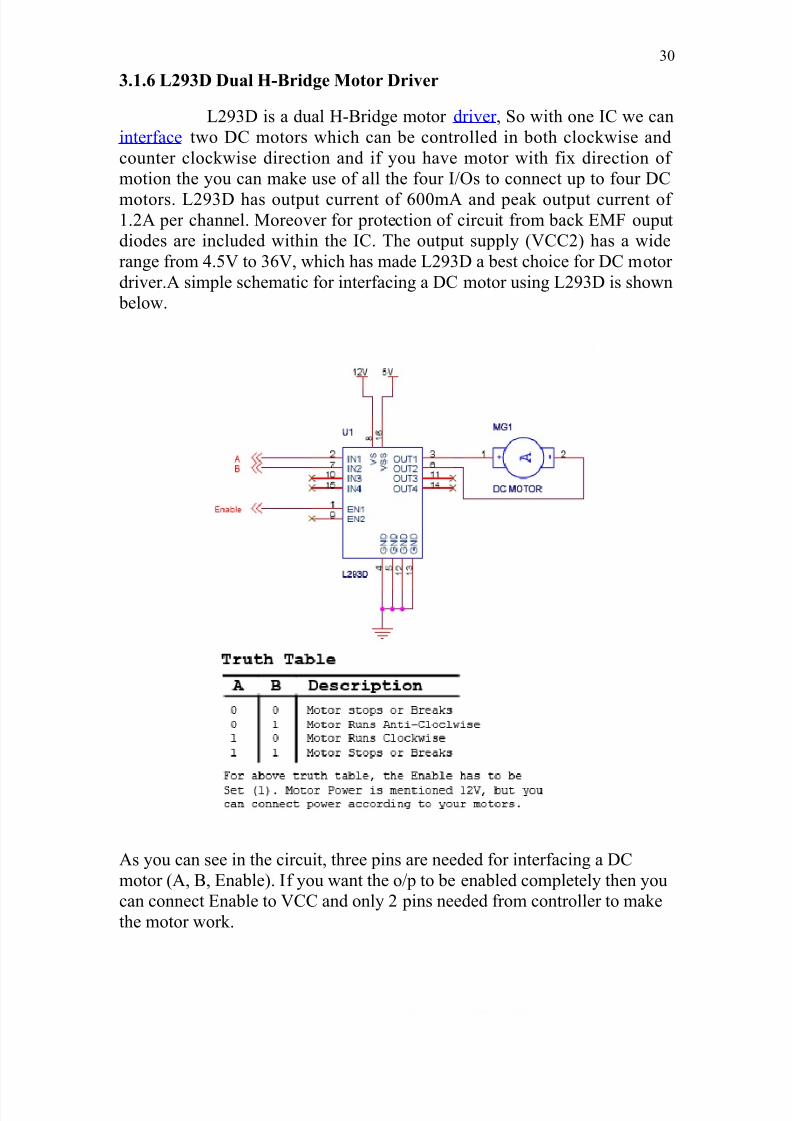
Truth Table
High Left High Right Low Left Low Right Description
On Off Off On Motor runs clockwise
Off On On Off Motor runs anti-clockwise
On On Off Off Motor stops or decelerates
Off Off On On Motor stops or decelerates
As already said, H-bridge can be made with the help of
transistors as well as MOSFETs; the only thing is the power handling
capacity of the circuit. If motors are needed to run with high current then lot
of dissipation is there. So head sinks are needed to cool the circuit.
So we have seen that using simple switching elements we can
make our own H-Bridge, or other option we have is using an IC based H-
bridge driver. Both of them are discussed in the next section of the tutorial.
29
8/3/2019 Web Based Robotics
http://slidepdf.com/reader/full/web-based-robotics 30/52
3.1.6 L293D Dual H-Bridge Motor Driver
L293D is a dual H-Bridge motor driver , So with one IC we can
interface two DC motors which can be controlled in both clockwise and
counter clockwise direction and if you have motor with fix direction of
motion the you can make use of all the four I/Os to connect up to four DC
motors. L293D has output current of 600mA and peak output current of 1.2A per channel. Moreover for protection of circuit from back EMF ouput
diodes are included within the IC. The output supply (VCC2) has a wide
range from 4.5V to 36V, which has made L293D a best choice for DC motor
driver.A simple schematic for interfacing a DC motor using L293D is shown
below.
As you can see in the circuit, three pins are needed for interfacing a DC
motor (A, B, Enable). If you want the o/p to be enabled completely then you
can connect Enable to VCC and only 2 pins needed from controller to make
the motor work.
30

8/3/2019 Web Based Robotics
http://slidepdf.com/reader/full/web-based-robotics 31/52
3.2 RS232 SERIAL CONNECTOR PIN ASSIGNMENT:
The RS232 connector was originally developed to use 25 pins. In this DB25
connector pinout provisions were made for a secondary serial RS232
communication channel. In practice, only one serial communication channel
with accompanying handshaking is present. Only very few computers have
been manufactured where both serial RS232 channels are implemented. Also
on a number of Telebit modem models the secondary channel is present. It
can be used to query the modem status while the modem is on-line and busy
communicating. On personal computers, the smaller DB9 version is more
commonly used today. The diagrams show the signals common to both
connector types in black. The defined pins only present on the larger
connector are shown in red. Note, that the protective ground is assigned to a
pin at the large connector where the connector outside is used for that
purpose with the DB9 connector version.
RS232 DB9 pinout
The pinout is also shown for the DEC modified modular jack. This type of
connector has been used on systems built by Digital Equipment Corporation;
in the early day’s one of the leaders in the mainframe world. Although this
serial interface is differential (the receive and transmit have their own
floating ground level which is not the case with regular RS232) it is possible
to connect RS232 compatible devices with this interface because the voltage
31

8/3/2019 Web Based Robotics
http://slidepdf.com/reader/full/web-based-robotics 32/52
levels of the bit streams are in the same range. Where the definition of
RS232 focused on the connection of DTE, data terminal equipment
(computers, printers, etc.) with DCE, data communication equipment
(modems), MMJ was primarily defined for the connection of two DTE's
directly.
32

8/3/2019 Web Based Robotics
http://slidepdf.com/reader/full/web-based-robotics 33/52
Ultrasonic Distance Sensor
Its compact size, higher range and easy usability make it a
handy sensor for distance measurement and mapping. The robot requires
means of detecting an obstacle (or another robot) without making physical
contact. This allows the robot to decide whether to avoid or to confront and
investigate the obstacle depending on its programming. Ultrasonic
transducers were chosen for this because they are more reliable and have a
greater range than IR sensors (effectiveness of IR sensors varies with
ambient light level).
3.2.1 Features
• Minimum range 10 centimeters
• Maximum range 400 centimeters (4 Meters)
• Accuracy of +-1 cm
• Resolution 0.1 cm
• 5V DC Supply voltage
• Compact sized SMD design
• Modulated at 40 kHz
• Serial data of 9600 bps TTL level output for easy interface with any
microcontroller
Specification:
Description Signal9-pin
DTE
25-pin
DCESource DTE or DCE
Carrier Detect CD 1 8 from Modem
Receive Data RD 2 3 from Modem
Transmit Data TD 3 2 from Terminal/Computer Data Terminal
ReadyDTR 4 20 from Terminal/Computer
Signal Ground SG 5 7 from Modem
Data Set Ready DSR 6 6 from Modem
Request to Send RTS 7 4 from Terminal/Computer
Clear to Send CTS 8 5 from Modem
Ring Indicator RI 9 22 from Modem
33
8/3/2019 Web Based Robotics
http://slidepdf.com/reader/full/web-based-robotics 34/52
Supply Voltage 5 V
Supply Current 15 mA
Output Data speed 9600 Bps
Output Data Format 8-N-1 8 data bytes, no parity, 1 stop bit
3.2.2 Pin Details:
1 – GND Supply Ground
2 - +5V Supply +5V
3 – Serial Out 9600 Serial output data (TTL 5V level) at 9600 baud rate
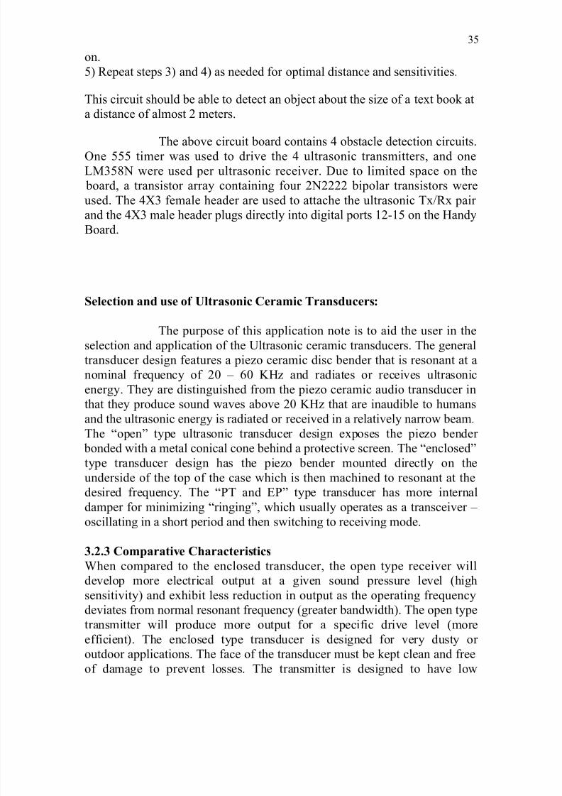
The IC U1 is a 555 timer in astable configuration to oscillate at 40 KHz.
Instead of using exact values for the two resistors that is placed between pin
6 and 7, a 10K ohm potentiometer (VR1) was used. This also allows for some fine tuning of the output frequency. The output (pin 3) is then attached
to a 40 KHz ultrasonic transmitter (UTR1).
The receiving circuit is a dual LM358N (U2) op-amp. A ultrasonic receiver
(UTR2) is connected to pin 3, the non-inverting input of U2a which is a non-
inverting amplifier with a gain of 220. The output of U2a is put through a
low pass filter via D1, C3 and R4 to produce a some what stable DC voltage.
This DC voltage is fed into the non-inverting input of U2b configured as a
non-inverting comparator. Sensitivity of U2b is controlled by VR2 to set the
threshold trigger value. The output of U2b is connected through R5 to the base of a bipolar 2N2222 transistor (Q1) acting as an inverter with a LED
(LED1) to indicate if an obstacle has been detected. Finally, the collector of
Q1 goes to the Handy Board's digital port (Handy Board uses inverted logic
levels, 0V is a logic 1 and +5V is a logic 0).
The following is the procedure to calibrate the circuit without the use of an
oscilloscope:
1) Adjust VR1 till the value between Vcc and pin 7 is approximately 1.2K
ohm.
2) Place UTR1 and UTR2 parallel to each other (about 1.5 inches apart) with
a solid object about 6 inches in front of them (similar to figures UTR1 and
UTR2 in the above schematic).
3) If LED1 is off, turn VR2 CW till LED1 is on and then back off a bit till it
is just off. If LED1 is on, turn VR2 CCW till LED1 is just off.
4) Adjust VR1 (should only be about 1/4 turn CW or CCW) till LED1 turns
34
8/3/2019 Web Based Robotics
http://slidepdf.com/reader/full/web-based-robotics 35/52
on.
5) Repeat steps 3) and 4) as needed for optimal distance and sensitivities.
This circuit should be able to detect an object about the size of a text book at
a distance of almost 2 meters.
The above circuit board contains 4 obstacle detection circuits.One 555 timer was used to drive the 4 ultrasonic transmitters, and one
LM358N were used per ultrasonic receiver. Due to limited space on the
board, a transistor array containing four 2N2222 bipolar transistors were
used. The 4X3 female header are used to attache the ultrasonic Tx/Rx pair
and the 4X3 male header plugs directly into digital ports 12-15 on the Handy
Board.
Selection and use of Ultrasonic Ceramic Transducers:
The purpose of this application note is to aid the user in the
selection and application of the Ultrasonic ceramic transducers. The general
transducer design features a piezo ceramic disc bender that is resonant at a
nominal frequency of 20 – 60 KHz and radiates or receives ultrasonic
energy. They are distinguished from the piezo ceramic audio transducer in
that they produce sound waves above 20 KHz that are inaudible to humans
and the ultrasonic energy is radiated or received in a relatively narrow beam.The “open” type ultrasonic transducer design exposes the piezo bender
bonded with a metal conical cone behind a protective screen. The “enclosed”
type transducer design has the piezo bender mounted directly on the
underside of the top of the case which is then machined to resonant at the
desired frequency. The “PT and EP” type transducer has more internal
damper for minimizing “ringing”, which usually operates as a transceiver –
oscillating in a short period and then switching to receiving mode.
3.2.3 Comparative CharacteristicsWhen compared to the enclosed transducer, the open type receiver will
develop more electrical output at a given sound pressure level (high
sensitivity) and exhibit less reduction in output as the operating frequency
deviates from normal resonant frequency (greater bandwidth). The open type
transmitter will produce more output for a specific drive level (more
efficient). The enclosed type transducer is designed for very dusty or
outdoor applications. The face of the transducer must be kept clean and free
of damage to prevent losses. The transmitter is designed to have low
35

8/3/2019 Web Based Robotics
http://slidepdf.com/reader/full/web-based-robotics 36/52
impedance at the resonant frequency to obtain high mechanical efficiency.
The receiver is constructed to maximize the impedance at the specified anti-
resonant frequency to provide high electrical efficiency.
3.2.4 Transmitter Drive Considerations
The ultrasonic transmitters can dissipate 200 mw rms continually.
Assuming a typical minimum series impedance of 500 ohms, the driver must
source 20 mA at 10 V rms.
A sine wave drive should be used to minimize harmonics that may
excite the transducer in an overtone mode (vibrate at a multiple of the
resonant frequency). For most models the maximum amplitude of the drive
waveform should be limited to 50 V pp. The transmitter dissipation must be
limited to an effective or average level of 200 mW by reducing the duty
cycle when the transmitter is dissipating more than 200 mW.
There are several oscillator circuits suitable for driving our ultrasonictransmitter, which have been widely used on security systems, remote
control and other applications. Please bear in mind that the circuits we
suggest sometimes need to be modified according to the different characters
of impedance, phase angle and resonant frequency while driving different
type of transmitters. Please refer to “Impedance Characteristics” carefully.
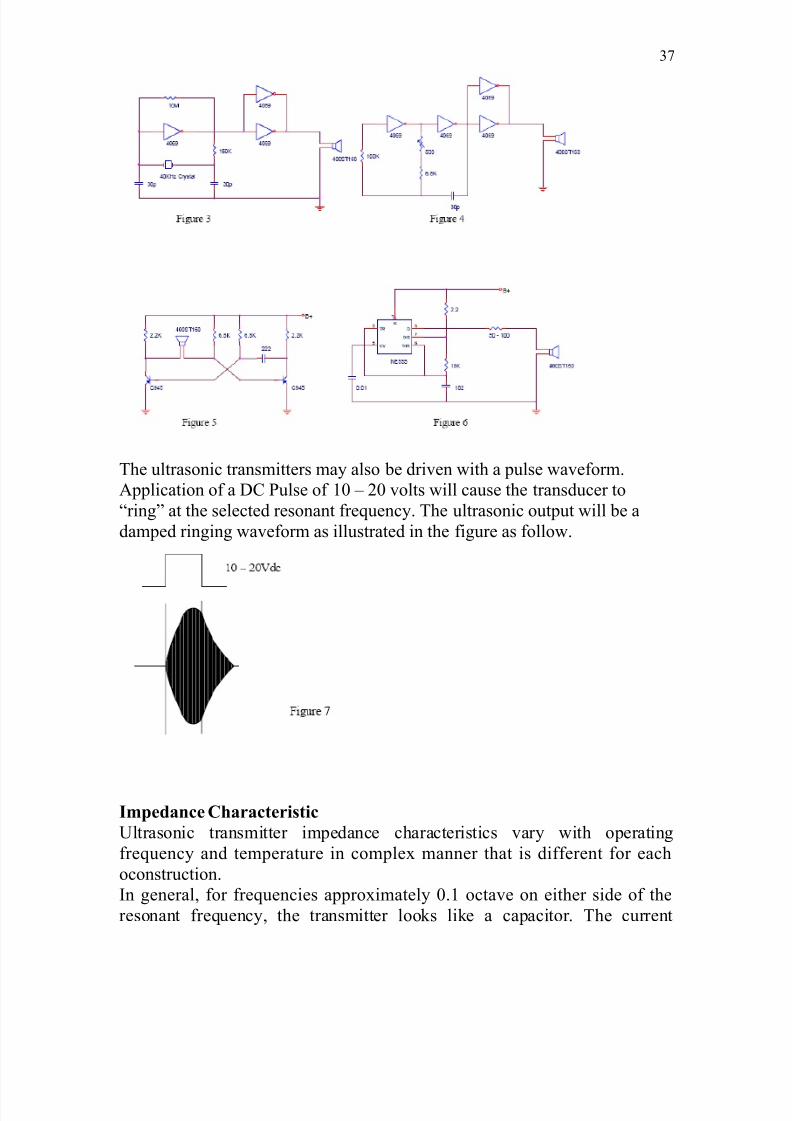
Suggestion Oscillating Circuits:
36
8/3/2019 Web Based Robotics
http://slidepdf.com/reader/full/web-based-robotics 37/52
The ultrasonic transmitters may also be driven with a pulse waveform.
Application of a DC Pulse of 10 – 20 volts will cause the transducer to
“ring” at the selected resonant frequency. The ultrasonic output will be a
damped ringing waveform as illustrated in the figure as follow.
Impedance Characteristic
Ultrasonic transmitter impedance characteristics vary with operating
frequency and temperature in complex manner that is different for each
oconstruction.
In general, for frequencies approximately 0.1 octave on either side of the
resonant frequency, the transmitter looks like a capacitor. The current
37
8/3/2019 Web Based Robotics
http://slidepdf.com/reader/full/web-based-robotics 38/52
through the transmitter will lead the voltage developed across the transmitter
by 90 degrees.
As the resonant frequency is approached, the voltage drop across the
transmitter will decrease to a minimum at the resonant frequency (minimum
series impedance) and the current will increase proportionally. The phase
lead to this current relative to the voltage will decrease to zero near the
resonant frequency and the transmitter will then appear to be a pure
resistance. As the frequency is increased above the resonant point, the
current may now lag the voltage by an increasing amount (maximum of 90
degrees) as the voltage across the transmitter climbs to a peak which is
defined as the anti-resonant frequency. During this transition, the transmitter
appears to have an inductive characteristic.Increasing temperature will lower
the resonant frequency and thus the point at which the phase changes will
occur.
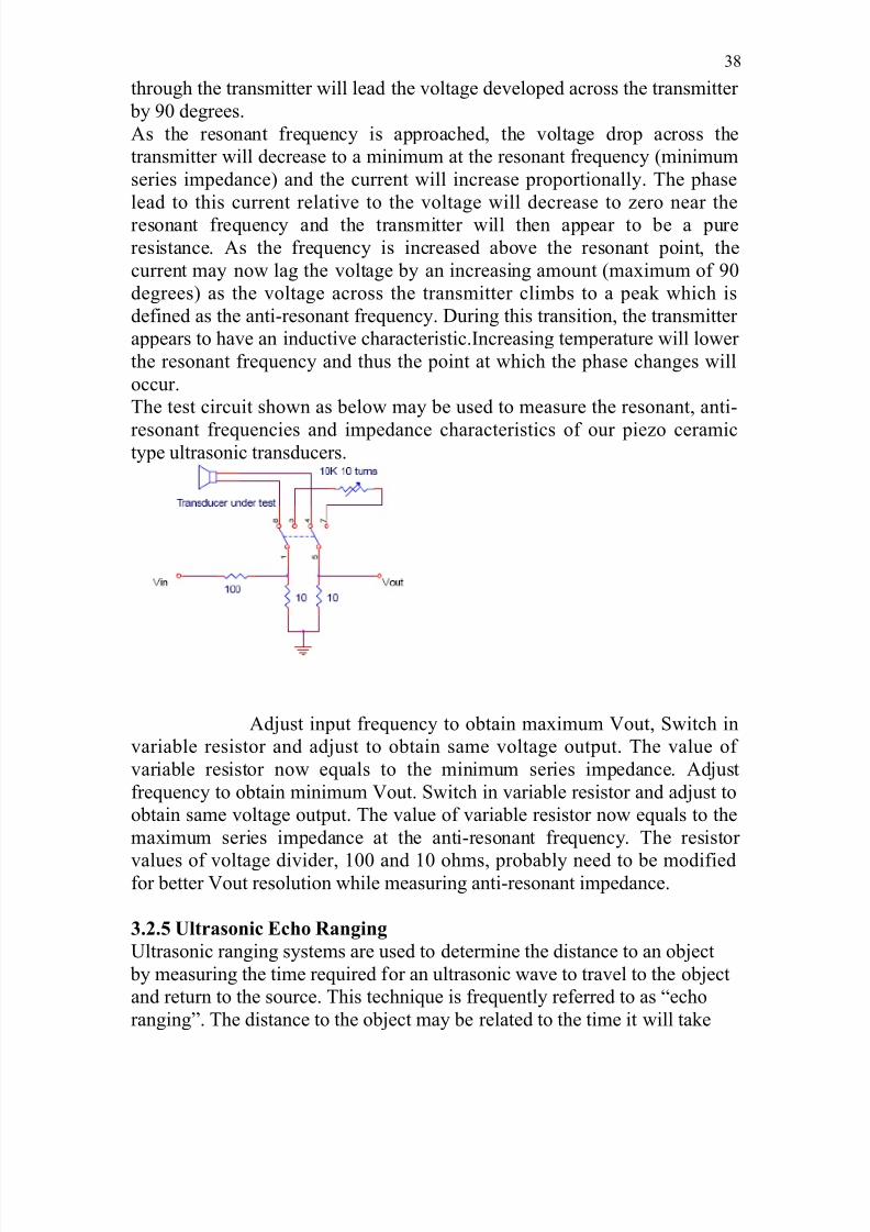
The test circuit shown as below may be used to measure the resonant, anti-
resonant frequencies and impedance characteristics of our piezo ceramictype ultrasonic transducers.
Adjust input frequency to obtain maximum Vout, Switch in
variable resistor and adjust to obtain same voltage output. The value of
variable resistor now equals to the minimum series impedance. Adjust
frequency to obtain minimum Vout. Switch in variable resistor and adjust to
obtain same voltage output. The value of variable resistor now equals to the
maximum series impedance at the anti-resonant frequency. The resistor
values of voltage divider, 100 and 10 ohms, probably need to be modifiedfor better Vout resolution while measuring anti-resonant impedance.
3.2.5 Ultrasonic Echo Ranging
Ultrasonic ranging systems are used to determine the distance to an object
by measuring the time required for an ultrasonic wave to travel to the object
and return to the source. This technique is frequently referred to as “echo
ranging”. The distance to the object may be related to the time it will take
38
8/3/2019 Web Based Robotics
http://slidepdf.com/reader/full/web-based-robotics 39/52
for an ultrasonic pulse to propagate the distance to the object and return to
the source by dividing the total distance by the speed of sound which is 344
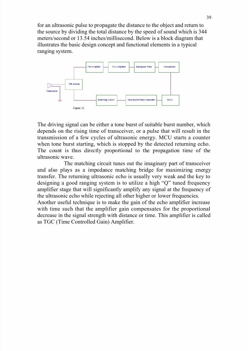
meters/second or 13.54 inches/millisecond. Below is a block diagram that
illustrates the basic design concept and functional elements in a typical
ranging system.
The driving signal can be either a tone burst of suitable burst number, whichdepends on the rising time of transceiver, or a pulse that will result in the
transmission of a few cycles of ultrasonic energy. MCU starts a counter
when tone burst starting, which is stopped by the detected returning echo.
The count is thus directly proportional to the propagation time of the
ultrasonic wave.
The matching circuit tunes out the imaginary part of transceiver
and also plays as a impedance matching bridge for maximizing energy
transfer. The returning ultrasonic echo is usually very weak and the key to
designing a good ranging system is to utilize a high “Q” tuned frequencyamplifier stage that will significantly amplify any signal at the frequency of
the ultrasonic echo while rejecting all other higher or lower frequencies.
Another useful technique is to make the gain of the echo amplifier increase
with time such that the amplifier gain compensates for the proportional
decrease in the signal strength with distance or time. This amplifier is called
as TGC (Time Controlled Gain) Amplifier.
39

8/3/2019 Web Based Robotics
http://slidepdf.com/reader/full/web-based-robotics 40/52
4. DESCRIPTION OF DEVELOPMENT SYSTEM
4.1 CROSS COMPILERS
First of all we begin this chapter by giving a brief introduction about
cross compilers in embedded programming and their applications. We know
that the execution of code in a microcontroller takes place as a hexadecimal
code. So we can program any microcontroller using an assembly language.
Also though the use of cross compilers we can program the microcontrollers
in any language like ‘C’ or ‘C++.
The cross compilers acts as a bridge between the programming
software and microcontrollers. Suppose we are programming the
microcontroller using ‘C’ the code written in ‘C’ language cannot be directly
executed by microcontroller. So this code written in ‘C’ is fed to a cross
compiler which converts into hexadecimal code which is understood and
executed by microcontroller. The advantages of using cross compilers is that
in case of some applications programming the microcontroller using
40

8/3/2019 Web Based Robotics
http://slidepdf.com/reader/full/web-based-robotics 41/52
assembly language will become bulk and tedious. So when we use cross
compilers we can program the microcontroller in any other language which
is easy to program and debug also. The commonly used cross compilers are
SDCC (Small devices C compiler), Keil etc.
In this our project the use of Keil cross compiler is to program the
microcontroller. In this chapter we discuss the introduction to programming
in Keil features of Keil and finally advantages of using Keil when compared
to other cross compilers. When we are writing program for any
microcontroller using cross compiler we cannot directly write the converted
code on to the microcontroller. This means we need to use a special
technique to load the program into the microcontroller. One of the methods
is to use a microcontroller with a flash memory. Flash memory is similar to
erasable programmable read only memory. So once program is written and
debugged using cross compiler, we need to flash the program on to the flash
memory of the memory. Once program is flashed the microcontroller is
loaded with the hex code and it will be ready for execution.
4.1.1 INTRODUCTION TO KEIL:
Keil software provides the premier 8051 development tools to
industry .The keil software comprises of different tool kits. A tool kit consist
of several application program that we can use to create our 8051 application
.When we use keil software for our project the development cycle is some
what similar to a software development project .It consist of creating source
file in C or assembly language compiling or assembling the source files
debugging error in the source file, linking file from complier and assembler
and finally building a project linking all the files and testing the linked
application.
41

8/3/2019 Web Based Robotics
http://slidepdf.com/reader/full/web-based-robotics 42/52
4.1.2 FUNCTIONING OF KEIL
All the files are created through the micro vision integrated
development environment are then passed to the C51 compiler or A51
assembler. The compiler and assembler process source files and create
relocatable object files. Object files created by the compiler or assembler
may be used by the library manager to create a library. A library is a
specially formatted, ordered program collection of object modules that linker
can process. When the linker processes a library, only the object modules in
the library necessary for program creation are used. Object files created by
the compiler and assembler and library files created by the library manager
are processed by the linker to create an absolute object module. An absolute
object file or module is an object file with no relocatable code. All the code
in an absolute object file resides at fixed locations.
The absolute object file created by the linker may be used to
program EPROM or other memory devices. The absolute object module may
also be used with the dScope-51 debugger / simulator or with an in-circuit
emulator. The dScope-51 source level debugger/simulator is ideally suited
for fast, reliable high-level-language program debugging. The debugger
contains a high-speed simulator and a target debugger that let you simulate
an entire 8051 system including on-chip peripherals. By loading specific I/O
drivers, we can simulate the attributes and peripherals of a variety of 8051
family. The RTX-51 real time operating system is a multitasking kernel for
the 8051 family. The RTX-51 real time kernel simplifies the system design,
programming, and debugging of complex applications where fast reaction to
time critical events is essential. The kernel is fully integrated into the
C51compiler and is easy to use. Task description tables and operating
42

8/3/2019 Web Based Robotics
http://slidepdf.com/reader/full/web-based-robotics 43/52
system consistency are automatically controlled by the BL51 code banking
linker/locater.
4.1.3 DEVELOPMENT TOOLS IN KEIL
The Fig 4.1 shows the full extent of the Keil Software 8051
development tools. The tools listed in this diagram comprise the professional
developer’s kit. In addition to the professional kit, Keil Software provides a
number of other tool kits for the 8051 developer. The most capable kit is the
professional developer’s kit is described as follows:
The professional developer’s kit includes everything the professional
8051 developer needs to create sophisticated embedded applications. This
tool kit includes the following components:
• C51 Optimizing C compiler,
•
A51 Macro Assembler,• BL51 Code Banking Linker/Locator,
• OC51 Banked Object file converter,
• OH51 Object-Hex converter,
• LIB51 Library Manager,
• dScope-1 Simulator/debugger,
•tScope-51 Target Debugger,
• Monitor-51 ROM Monitor and Terminal Program,
• Integrated Development Environment,
• RTX-51 Tiny Real-Time Operating System.
43
8/3/2019 Web Based Robotics
http://slidepdf.com/reader/full/web-based-robotics 44/52
In addition, the professional developer’s kit includes the following tools for
Windows users:
• dScope-51 Simulator/Debugger for windows,
• Micro Vision/51 Integrated Development Environment for
windows.
The professional developer’s kit can be configured for all 8051 derivatives.
The tools included in this kit can run any compatible computer.
4.1.4 C51 OPTIMIZING C CROSS COMPILER
The C programming language is a general-purpose programming
language that provides code efficiency, elements of structured programming,
and a rich set of operators. Its generality, combined with its absence of restrictions, make C a convenient and effective programming solution for a
wide variety of software tasks. Many applications can be solved more easily
and effectively with C than with other more specialized languages. The Keil
software C51 optimizing cross compiler for the MS-DOS operating system
is a complete implementation of the ANSI (American National Standards
Institute) standard for the C language. The C51 compiler generates code for
the 8051 microprocessor but is not a universal C compiler adapted for the
8051 target. It is a ground-up implementation dedicated to generating
extremely fast and compact code for the 8051 microprocessor. For most
8051 applications, the C51 compiler gives software developers the flexibility
of programming in /c while matching the code efficiency and speed of
44

8/3/2019 Web Based Robotics
http://slidepdf.com/reader/full/web-based-robotics 45/52
assembly language. Using a high-level language like C has many advantages
over assembly language programming. For example:
Knowledge of the processor instruction set is not required. A
rudimentary knowledge of the 8051’s memory architecture is
desirable but not necessary.
Register allocation and addressing mode details are managed by the
compiler.
The ability to combine variable selection with specific operations
improves program readability.
Keywords and operational functions that more nearly resemble the
human thought process can be used.
Program development and debugging times are dramatically reduced
when compared to assembly language programming.
The library files that are supplied provide many standard routines
(such as formatted output, data conversions, and floating-point
arithmetic) that may be incorporated into our application.
Existing routine can be reused in new programs by utilizing modular
programming techniques available with C.
The C language is very portable and very popular. C compilers are
available for almost all target systems. Existing software investments
can be quickly and easily converted from or adapted to other
processors or environments.
4.1.5 A51 MACRO ASSEMBLER
The A51 assembler is a macro assembler for the 8051 microcontroller
family. It translates symbolic assembly language mnemonics into relocatable
45

8/3/2019 Web Based Robotics
http://slidepdf.com/reader/full/web-based-robotics 46/52
object code where the utmost speed, small code size, and hardware control
are critical. The macro facility speeds development and conserves
maintenance time since common sequences need only be developed once.
The A51 assembler supports symbolic access to all features of the 8051
architecture and is configurable for the numerous 8051 derivatives. The A51
assembler translates an assembler source file into a relocatable object
module. If the DEBUG control is used, the object file contains full symbolic
information for debugging with dScope or an in-circuit emulator. In addition
to the object file, the A51 assembler generates a list file which may
optionally include symbol table and cross reference information. The A51
assembler is fully compatible with Intel ASM-51 source modules. The A51
assembler supports all members of the 8051 family. The special function
register (SFR) set of the 8051 is predefined. However, the NOMOD51
control lets you override these definitions with processor-specific include
files. The A51 assembler is shipped with include files for the 8051, 8051fx,
8051GB, 8052, 80152, 80451, 80452, 80515, 80C517, 80C517A, 8x552,
8xC592, 8xCL782, 8xCL410 and 80C320 microcontrollers. You can easily
create include files for other 8051 family members.
4.1.6 BL51 CODE BANKING LINKER/LOCATOR
The 51 code banking linker /locator combines one or more object
modules into a single executable 8051 program. The linker also resolves
external and public references, and assigns absolute addresses to relocatable
programs segments. The BL51 code banking linker/locator processes object
modules created by the keil C51 compiler and A51 assembler and the Intel
PL/M-51 compiler and ASM-51 assembler. The linker automatically selects
the appropriate run-time library and links only the library modules that are
46

8/3/2019 Web Based Robotics
http://slidepdf.com/reader/full/web-based-robotics 47/52
required. Normally, you invoke the BL51 code banking linker/locator from
the command line specifying the names of the object modules to combine.
The default controls for the BL51 code banking linker/locator have been
carefully chosen to accommodate most applications without the need to
specify additional directives. However, it is easy for us to specify custom
settings for your applications.
4.1.7 OC51 BANKED OBJECT FILE CONVERTER
The OC51 banked object file converter creates absolute object
modules for each code bank in a banked object module. Banked object
modules are created by the BL51 code banking linker/locator when you
create a bank switching application. Symbolic debugging information is
copied to the absolute object files and can be used by dScope or an in-circuit
emulator. We may use the OC51 banked object file converter to create
absolute object modules for the command area and for each code bank in
your banked object module. You may then generate Intel HEX files for each
of the absolute object modules using the OH51 object-hex converter.
4.1.8 OH51 OBJECT-HEX CONVETER
The OH51 object-hex converter creates Intel hex files from absolute
object modules. Absolute object modules can be created by the BL51 code
baking linker or by the OC51 banked object file converter. Intel hex files are
ASCII files that contain a hexadecimal representation of your application.
They can be easily loaded into a device programmer for writing on Erasable
programmable read only memory.
47
8/3/2019 Web Based Robotics
http://slidepdf.com/reader/full/web-based-robotics 48/52
LIB51 LIBRARY MANAGER
The LIB51 library manager lets you create and maintain library files.
A library file is a formatted collection of one or more object files. Library
files provide a convenient method of combining and referencing a large
number of object files. Libraries can be effectively used by the BL51 code
banking linker/locator. The LIB51 library manager lets you create a library
file, add object modules to a library file, remove object modules from may
be controlled interactively or from the command line.
DSCOPE-51 FOR WINDOWS
DScope-51 is a source level debugger and simulator for programs
created with the keil C51 compiler and A51 assembler and the Intel PL/M-
51 compiler and ASM-51 assembler. DScope-51 is a software-only product
that lets us simulate the features of an 8051 without actually having target
hardware. We may have used Scope-51 to test and debug our embedded
applications before actual 8051 hardware is ready. DScope-51 simulates a
wide variety of 8051 peripherals including the internal serial port, external
I/O, and timers.
4.1.9 µVISION/51 FOR WINDOWS
Microvision/51 is an integrated software development platform that
includes a full function editor, project manager, make facility, and
environment control for the keil 8051 tools. When we use µVision/51 speeds
our embedded applications development by providing the following:
48

8/3/2019 Web Based Robotics
http://slidepdf.com/reader/full/web-based-robotics 49/52
Standard Windows user interface,
Dialog boxes for all environment and development tool
settings,
Multiple file editing capability,
Full function editor with user-definable key sequences,
Application manager for adding external programs into the
pull-down menu,
Project manager for creating and maintaining projects,
Integrated make facility for building target programs from your
projects,
On-line help system.
4.2 TARGET PROCESSOR
In our project microcontroller AT89C52 (Target processor) is used to
governs all the essential process which has to be executed during
acquisition.Microcontroller, as the name suggests, are small controllers. These are like single
chip computers that are often embedded into systems to function as processing
/controllers unit. For example, the remote control you are using probably has
microcontrollers inside that do decoding and other controlling functions. They are
also used in automobiles, washing machines, microwave ovens, toys…etc, where
automation is needed. The key features of microcontrollers include:
• High integration of Functionality
Microcontrollers sometimes are called single chip computers because they
have on-chip memory and I/O circuitry and other circuitries that enable
49

8/3/2019 Web Based Robotics
http://slidepdf.com/reader/full/web-based-robotics 50/52
them to function as small standalone computers without other supporting
circuitry.
• Field Programmability, Flexibility
Microcontrollers often use EEPROM or EPROM as their storage device to
allow field programmability so they are flexible to use. Once the program
is tested to be correct then large quantities of microcontrollers can be
programmed to be used in embedded systems.
• Easy to Use
Assembly language is often used in microcontroller and since they usually
follow RISC architecture, the instruction set is small. The development
package of microcontrollers often includes an assembler ,a simulator ,a
programmer to “ burn “ the chip and a demonstration board .Some
packages include a high level language compiler such as a C compiler and
more sophisticated libraries.
5. APPLICATION SOFTWARE
5.1 APPLICATION SOFTWARE DISCRIPTION
The application software is a virtual representation of the actual
instrument and provides all facilities for the user to control the working of
the motor. This technique of operating the motor (the actual instrument) is
highly advantageous, as it does not permit the actual instrument to be
misused, for example, here, the minimum and maximum speed of the motor
is defined and hence prevents the user from exceeding the speed limits. Thus
the application software provides high security to the actual instrument.
Moreover certain graphical representation of the real time values with high
resolution can also be implemented.
This software facilitates the user to turn on/off the motor, speed
control and direction control of the motor. When the ON/OFF buttons are
50

8/3/2019 Web Based Robotics
http://slidepdf.com/reader/full/web-based-robotics 51/52
pressed, two unique values corresponding to the on/off states are transmitted
serially, which is identified by the microcontroller. A slider allows the user
to set the speed of the motor. The actual speed of the motor is sensed by the
opto-interrupter and is transmitted serially to the application through suitable
signal conditioning circuitry. Thus the application software is continuously
updated with the current speed of the motor. Simultaneously a real time
graph of the actual speed of the motor is plotted. Also there is virtual
representation of the motor shaft, which rotates corresponding to the speed
of the motor..
Thus a real time control of the motor is obtained through the application
software
5.2. SCREEN SHOTS
51

8/3/2019 Web Based Robotics
http://slidepdf.com/reader/full/web-based-robotics 52/52
6. CONCLUTION
In this project we designed an obstacle sensing robot. When ever the
robot finds any obstacle in front of it suddenly deviates its path in the
automatic mode. The user can also control the robot through the web and
monitoring is also possible in client as well as server side, in the manual
mode.
We used visual basic for the design of application software and
embedded ‘C’ to program the embedded microcontroller.
52